1
®
Environmentally friendly technology
OPERATOR
MANUAL
PROPANE POWERED LINE TRIMMER
ECO-TRIMMER
MODELS: ST
ST
ST
ST
TABLE
025SS
025DC
025CS
025DS
OF CONTENTS
2
Service and Safety....................................................................................
3
Safe Operation Rules.....................................................................................
4
Understanding Your Trimmer...............................................................
5
Assembly .....................................................................................................
Oil Informatiou .........................................................................................
6
7
Understanding Propane..............................................................................
8
Installing the Propane Canister:......................................................
9
Installing Attachments ..................................................................................
10
Starting / Stopping ...............................................................................
11
Operation ..................................................................................
Maintenance ...........................................................................................
t2
19
Cleaning and Storage ..............................................................................
19
Troubleshooting ......................................................................................
20
Speci=_cations.......................................................................................
2t
Warranty..............................................................................................
DO NOT RETURN THE UNIT
TO THE RETAILER
Call 1-866-941-LEHR
THE ENGINE EXHAUST
(5347)
FROM THfS
PRODUCT CONTA1NS CHEMICALS
KNOWN TO THE STATE OF CALIFORNIA
TO CAUSE CANCER, BIRTH DEFECTS
OR OTHER REPRODUCTIVE
HARM
WARNING:
I
J
J
LEH RI ALL
RIGHTS
RESERVED
2008-2009
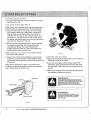
IMPORTANT SAFETY INSTRUCTIONS
READ ALL INSTRUCTION
BEFORE OPERATING
LEHR ECO-TRIMMER
4-CYCLE PROPANE TRIMMER
For service call 1-866-941-LEHR in the United States, to
obtain a list of authorized service dealers near you°
For more details about your unit, visit our website at:
www.golehrocom.
. Inspect the unit before use, Replace damaged parts,
. Check for fuel leaks,, Make sure all fasteners are in place
and secure. Replace parts that are cracked, chipped,
or damaged in any way, Do not operate the unit with
loose or damaged parts.
DO NOT RETURNTHE UNIT TO THE RETAILER.
PROOFOF PURCHASEWILL BE REQUIREDFOR
WARRANTY SERVICEr
. Carefully inspect the area before starting the uniL
Remove all debris and hard or sharp objects such as
glass, wire, etc
THIS PRODUCTIS COVEREDBY ONE OR MORE
UoSoPATENTS,OTHER PATENTSARE PENDING
• Be aware of the risk of injury to the head, hands and
feet°
Service on this unit both within and after the warranty
period should be performed only by an authorized and
approved service dealer,
• Clear the area of children, bystanders, and pets. At
a minimum, keep all children, bystanders, and pets
outside a 50 feet (t 5 m_)radius; there still may be a risk
to bystanders from thrown objects. Bystanders should
be encouraged to wear eye protection, If you are
approached, stop the unit immediately,
SPARK ARRESTOR NOTE
NOTE: For users on U.,S..Forest Land and in the states
of California, Maine, Oregon, and Washington. All U.S.
Forest Land and the State of California (Public Resources
Codes 4442 and 4443), Oregon, and Washington require
by law that certain internal combustion engines operated
on forest brush and/or grass-covered areas be equipped
with a spark arrestor, maintained in effective working order,
or the engine be constructed, equipped and maintained
for the prevention of fire. Check with your state or local
authorities for regulations pertaining to these requirements.
Failure to follow these requirements could subject you to
liability or a fine This unit is factory equipped with a spark
arrestor,
• Use only original equipment manufacturer replacement
line, Never use metal-reinforced line, wire or rope°
These can break offand become dangerous projectiles,,
. Squeeze the throttle control and check that it returns
automatically to the idle position° Make all adjustments
or repairs before using unit,,
• Do not operate this unit when tired, ill, under the
influence of alcohol, drugs or medications.
All information, illustrations, and specifications in this
manual are based on the latest production information
available at the time of printing., We reserve the right to
make changes at any time without notice°
I
V_EN
USINGTHE
. This unit is intended for adult use only Do not allow
children or untrained individuals to use the unit,
• Familiarize yourself with the controls and proper use of
your trimmer prior to using,,
WHEN SERVICING,USE ONLY IDENTICAL
UNIT, YOU MUST
REPLACEMENTPARTS
USE OF ANY OTHER
PARTS MAY CREATE A HAZARD OR CAUSE
FOLLOWTHESESAFETYRULES.PLEASE
READTHESETO ENSURETHESAFETYOF
THE OPERATOR
WARNING:
AND ANY BY ST ANDER&
PLEASE KEEPTHESE INSTRUCTIONS
FOR
1
I
DAMAGE
WARNING:
PRODUCT
]
LATER USE.
J
2
LEH R tALL RIGHTS RESERVED
2008-2009
DURING
OPERATION
• Never start or run the unit inside a closed room or build ing. Breathing exhaust fumes can be fatal Operate this
unit only in a well ventilated outdoor area.
• Wear safety glasses or goggles that meet ANSI Z87,1
standards and are marked as such Wear earlhearing
protection when operating this unit Wear a face or dust
mask if the operation is dusty,
. Wear heavy long pants, boots, gloves and a long sleeve
shirt., Do not wear loose clothing, jewelry, short pants,
sandals or go barefoot. Secure hair above shoulder
level,,
• Do not operate the engine faster than the speed needed
to cut, trim or edge Do not run the engine at high speed
when not cutting
• Always stop the engine when cutting is delayed or when
walking from one cutting location to another,,
• If you strike or become entangled with a foreign object,
stop the engine immediately and check for damage Do
not operate before repairing damage,. Do not operate the
unit with loose or damaged parts, Stop the unit, switch
the engine to off, and disconnect the spark plug for
maintena nce or repair
• The cutting attachment shield must always be in place
while operating the unit as a trimmer,, Do not oper ate unit without both trimming lines extended, and the
proper line installed, Do not extend the trimming line
beyond the length of the shield°
• Use only original equipment manufacturer replacement
parts and accessories for this unit. These are available
from your authorized service dealer_ Use of any unau
thorized parts or accessories could lead to serious injury
to the user, or damage to the unit, and void your war ranty_
• This unit has a clutch,, The cutting attachment remains
stationary when the engine is idling If it does not, have
the unit adjusted by an authorized service technician,
• Keep unit clean of vegetation and other materials, They
may become lodged between the cutting attachment
and shield,
• Adjust the handle to your size in order to provide the
best grip,
a To reduce fire hazard, replace faulty muffler and spark
arrestor., Keep the engine and muffler free from grass,
leaves, excessive grease or carbon build up
. Be sure the cutting attachment is not in contact with
anything before starting the unit,
. Use the unit only in daylight or good artificial light,.
- Avoid accidental starting Be in the starting position
whenever pulling the starter roper The operator and
unit must be in a stable position while starting, Refer to
Starting/Stopping Instructions_, (p,,10) ,
. Only use this tool for its intended purpose,
• Do not overreach, Always keep proper footing and balance_
• Always hold the unit with both hands when operating
Keep a firm grip on both handles or grips,.
• Keep hands, face, and feet at a distance from all mov ing parts, Do not touch or try to stop the cutting attach ment when it rotates.
, Do not touch the engine, gear housing or muffler. These
parts get extremely hot from operation, even after the
unit is turned off,,
OTHER SAFETY WARNINGS
• Never store a unit with propane canister attached inside
a building where vapor may reach an open flame or
spark.,
- Allow the engine to cool before storing or transporting_
Be sure to secure the unit while transporting,,
• Store the unit in a dry area, locked up or up high to
prevent unauthorized use or damage, out of the reach of
children,
• Never douse or squirt the unit with water or any other
liquid_ Keep handles dry, clean and free from debris,
Clean after each use, see Cleaning and Storage instruc tions., (p19)
• Keep these instructions Refer to them often and use
them to instruct other users, if you loan someone this
unit, also loan them these instructions_
SAVE THESE INSTRUCTIONS
LEHR I ALL RIGHTS RESERVED 2008-2009
3
SAFETY AND INTERNATIONAL
SYMBOLS
This operator's manual describes safety and international
Read
the
operator's
WARNING:
manual
for complete
Indicates danger, warning
May be used in conjunction
plctogr_phs
WARNING:
READ
Read the operators
safety,
assembly,
symbols and pictographs that may appear on this product
operating
and
OPERATOR'S
and
repair
information,
or caution
ONtOFF STOP CONTROLS ONfSTART/RUN
with other symbols or
manual(s)
maintenance
MANUAL:
ON/OFF STOP CONTROL OFF or STOP
and follow all warnings
and safety instructions. Failure to do so can result In
serious injury to the operator andtor bystanders
WEAR
EYE AND HEARING
Thrown
objects and loud noise can cause severe eye
PROTECTION
WARNING:
ANSI
standardsloss..
and
ear eye
protection
whenmeeting
injury Z87.
and t heating
Wear
protection
operating this unit, Use a full face shield when needed.
15m
(S04
KEEP SYSTANDERS
___
HOT
OIL: Refer to operator's
AWAY
WARNING:
Keep all bystanders, especially children and pets, at
least S0 feet (I 5 m) from the operating area.
SURFACE
WARNING
Do not touch a hot muffler, gear housing or o/tinder. You
may get burned.These parts get extremely hot from opera fiord,They remain hot for a short time after the unit turned off
manual for the proper type of oil,
THROWN OBJECTS AND ROTATING CUTTER CAN
CAUSE SEVERE INJURY WARNING:
SHARP
BLADE
WARNING
Sharp blade on cutting
Do not operate without the cutting attachment shield tn
place,,Keep away from the rotating cutting attachment,
attachment
shield
serious injury, do not touch the line cutting
To prevent
blade
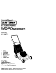
Starter Rope
Gdp
Safety
Trigger
Spark Plug
Cover
OnlOfl
D-Handte
Shaft
Housing
Shaft Gnp
Throtlle
Control
OTHER
OPTIONAL
ACCESSORIES
iter
Cover
Propane Canisler
MAY BE USED
WITH
YOUR
UNIT
J
4
LEHR I ALL
RIGHTS
RESERVED
2008-2009
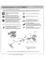
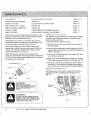
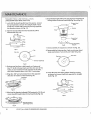
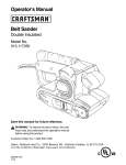
INSTALLING
CUTTING
ATTACHMENT
SHIELD
Use the following instructions if the cutting attachment
shield on your unit is not installed, Use only the
instructions that apply to the type of shaft and shield
that your unit is equipped with,.
FOR CURVED SHAFT TRIMMERS
Place the cutting attachment shield and spacer against
tube as shown in (Fig. 1), Use the 2 screws provided
to clamp the cap and shield onto the tube. Tighten the
screws evenly. Make sure the shield does not touch
any rotating parts,
CuttingAttachment Shield
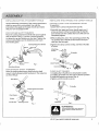
INSTALLING
THE D-HANDLE
AND LOWER HANDLE
STRAIGHT SHAFT AND ACCESSORY READY
TRIMMERS
1,,Locate the 4 screws includedin the tool kit,
2.Assemble the upper and lower handle parts and 4
screws as shown in (Fig. 3), positioning the handle
parts evenly over the rubber sleeve on shaft. Do not
completely tighten.
3.While holding the unit in the operating position (Fig..
14), position the D-handle to the location that provides you the best grip.
&Tighten the clamp screws evenly, until the D-Handle
is secure_
Attaching
Screws
"_'I
f
_
(__!.
Cap
D-Handle
Lower Handle
"" Washer
Fig.
Attaching Screws
FOR STRAIGHT
Fig..3
SHAFT TRIMMERS
Place the cutting attachment shield onto the shaft
mount.. Install using provided hardware in the sequence
as shown (Fig,2)_
Sha_ Mount
CURVED SHAFTTRIMMERS
1, Installing the D-Handle (non detachable model).,
2,.Installing D-Handle over the tube in desired position,
3, Install the fasteners as shown (Fig,,4)_
&Tighten until D-Handle is secure.
uttingAttachment Shield
Plate Washer
W ,he,
Lock Washer
jx
Attach
! Screws
Fig 2
To proven1 sedous injury, never operale the
trimmer wllhoul the culting attachment in
place,
I
LEHR I ALL
WARNING:
RIGHTS RESERVED2008-2009
1
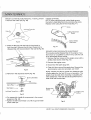
RECOMMENDED
OIL TYPE
2. Place the unit on a level surface (fig.6).
Using the proper type and weight of oil in the crankcase
is extremely important. Check the oil before each use
and change the oi! regularly. Failure to use the correct oil,
or using dirty oil, can cause premature engine wear and
failure.. Usea high-quality SAE 10W-30 weight oil of API
(American Petroleum Institute) service class SF,SG, SH.
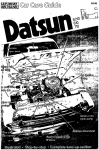
ADDING OiL TO THE CRANKCASE
INITIAL USE
NOTE:This unit is shipped without oil In order to avoid
damage to the unit, put oil in the crankcase before you
attempt to start the unit
Fig, 6
Your unit is supplied with one 1.7 fluid oz (50 mL) bottle
ofSAE 10W- 30 SF,SG orSH oil (Fig. 5)_
NOTE:Save the bottle of oil. It can be used to measure
the correct amount during future oil changes. See
Changing The Oil (p.13).
3,.Remove the oil plug I dipstick from the crankcase (FigoT).
4. Pour the entire bottle ofoil into the oil fill hole (Fig° 7)°
t. Unscrew the top of the bottle ofoil and remove the
seal covering the opening_ Replace the top., (Fig,,S),
\
oil Fill Hole
Fig, 7
Check oil before each use and change as needed. Refer
to Changing the Oil (p13),
Fig S
5, Wipe up any oil that may have spilled and reinstall
the oil plugldipstick.
WARNING:
Overfilling crankcase reay c,_use hal oil to ddp |rare
air _ale_ and smoke to come oh1 Item the exhaust,
Check and maintain the p_'opo_toil _evel in the crank
caee; it _s ireportant and c_nnoI be overemphe_zedCheck the oil before each usa an_ change as
needed. See Changtng the On 11_t3)
J
6
LE H R I ALLRIGHTSRESERVED
2008-200g
SAFETY WARNINGS
FOR PROPANE
UNITS
NOTE:Use propane only in containers specifically
designed and approved for this unit., Propane is a
combustible gas, it is colorless and thus invisible to the
naked eye. Propane has a harmless odorant added so
that it is possible to smell it..The user should be familiar
with the smell of propane (smells like sulfur or rotten
eggs). If at any time the smell of propane is identified,
turn off the engine_, If the leak persists, remove the pro pane canister,.Never attempt to operate a unit that has
a suspected leak, Always remove the propane canister
from any unit that has a suspected leak.,
CARBON MONOXIDE HAZARD
Burning propane makes Carbon Monoxide (CO). CO is
invisible, has no smeli and can kill you.. Operating your
trimmer in an enclosed area can be dangerous.
I. Use only in well ventilated areas°If you experience
headache, drowsiness, or nausea, turn unit off and
get fresh air quickly.
2..Never use where people are sleeping_
3. Follow unit instructions for proper use°
HANDLING & STORAGE
I., Keep out of reach of children_
2, Never expose cylinder to heat, sparks, or flame,
Never leave in direct sunlight., Never store at tem peratures above 120 degrees F° (49_C)..
3oNever store in living spaces.
4, Always use cylinder until it is completely empty,.
5'LNever refill a disposable cylinder. Refilling may cause
an explosion° Federal law forbids transportation if re filled, a penalty up to $500,000, and 5 years impris onment (49 U.S_C.S124)_
6oNever put in luggage or take on trains or aircraft..
7_To discard, contact local refuse hauler or recycle ten ter. Never put in fire or incinerator,. Do not puncture. If
your cylinder was purchased with a "Green Key"* or
similar device, install it when empty and cylinder may
be recycled with other steel items..
NOTE: FIRE!EXPLOSIONHAZARD
Contains enough gas to cause serious fire, explosion,
and burns.To reduce chance of leak, fire, or explosion,
take the following precautions:
BEFOREUSE
I.. Check cylinder and appliance seals. Never use with
damaged or missing seals..Discard cylinder if dirt or
rust particles are in valve area.
2. Turn trimmer off°
3. Attach cylinder outdoors away from pilot lights, flames,
sparks or other ignition sources..These sources can
ignite lealdng gas..
4..Hand tighten only. Never use tools to tighten. Overtightening can damage seals.
S..Check for leaks. Put soapy water on connections.
Look for bubbles,. Listen for hiss of escaping gas..Feel
for extreme cold.. Smell for rotten egg odor. Do not
use if leaking°
6. Read and follow appliance instructions,.
DURING USE
Never use near pilot lights, flames, sparks, or other
ignition sources°They can ignite leaking gash
AFTERUSE
1..Turn trimmer offand let cool,.
2. Detach cylinder when not in use.
3_Detach outdoors away from pilot lights, flames, sparks,
or other ignition sources,they can ignite leaking gas
4..Replace cap to keep valve clean.
IN CASEOF FIRE
1oLeave area quickly and call for helpo
2. Let cylinder burn out..
PROPANEIS HIGHLYFLAMMABLE, |
AND ITSVAPORSCAN EXPLODEIF 1
IGNITED,.
!
"Green Key- is a trademark of the Coleman company
............
, ...............
9
LEHR I ALL RIGHTS RESERVED 2008-2009
7
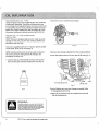
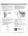
USETHECORRECT
PROPANE
CANISTER
Always
usePropane
canisters
or"Bottles" that are the
correct size. The 17 ounce or 16.4 ounce/465 g can isters that are approximately 3-7/8 inches (9°5 cm) in
diameter are the correct canisters (Fig. 8). Do not use
the smaller diameter canisters as they will not latch
securely to the unit and vibration may cause damage to
the trimmer and potentially result in a dangerous leak
Propane
Connector
Fig, 9B
REMOVING
THE PROPANE
CANISTER
1oMake sure the engine is off
2. Un-latch the bottle clamp and push canister against the
guard exposing the propnae connector,. Remove the
propane connector by turning it counterclockwise,,
Fig. 8
A_ACHING
THE PROPANE
1.,Make sure the engine is off
3oRemove the empty canister.
CANISTER
4. Dispose of empty propane canisters in accordance
to Federal, State and local Regulations,
2. If the propane canister to be installed has a protec
rive plastic cap over the threaded end, remove it,,
Make sure the canister clamp is in the un-latched
position°
WARNING:
NEVER ATTEMPT TO FORCE A CONNEC_
TOR ONTO A PROPANE CANISTER THAT
HAS IMPROPER OR DAMAGED THREADS
3oInsert the threaded end of the propane canister into
the clamp as faras it will go (Fig, 9A),,Insert the propane connector onto the threaded end of the canister and screw it
onto threads clockwise (Fig. 9B).. Screw it until snug,,
Do not over tighten,, It may be normal to hear or smell
a slight momentary leak of propane as the connector
is being screwed ino Make sure that the connector is
installed tight enough that any leakage stops, Hand
tight is sufficient. Slide canister back so all of fue_ line
components are behind the guard and latch the canister
clamp.
J
"x
WARNING:
THISCONTAINERAND 8Y-PRODUCTSOF THE
COMBUST]0N OF ITS CONTENTSCONTAIN
CHEMICALSKNOWNTO THESTATEOF
CALIFORNIATO CAUSECANCER, BIRTH
DEFECTSOR OTHERREPRODUCTIVEHARM,
--
EXTREMELY FLAMMABLE FIRE/EXPLO_
SION HAZARD CONTENTS UNDER
PRESSURE CARBON MONOXIDE
WARNING:
HAZARD,
/
/
[
1
J
f
WARNING:
PROPANE
tSEXTREMELY
FLAMMABLE
Clamp
Fig 9A
VAPOR MAY EXPLODE. ALWAYS STOP
THE ENG{NE AND ALLOW iT TO COOL
BEFORE REPLACING THE PROPANE
CANISTER. DO NOT SMOKE. KEEPS
SPARKS AND OPEN FLAMES AT A
DISTANCE PROM THE AREA
.j
8
LE H R I ALL RIGHTS
RESERVED
2008-2009
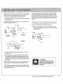
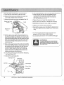
INSTALLING CUTTING ATTACHMENTS OR ADD-ONS
NOTE: Place the unit on the ground or on a work bench
to make accessory installation or removal easier,.
l o3brn knob counterclockwise to loosen (Fig, 10)o
2oWhile firmly holding the attachment, push it straight into
coupler (Fig_10),
NOTE:Aligning the release button with receiving hole
will help installation (Fig, 10)o
REMOVING CUTTING ATTACHMENTS OR ADD*ONS
t,,Turn the knob counterclockwise to loosen (Fig,,12),
2, Pressand hold the release button {Fig,,12),
Line up parts
Coupler
Receiving Hole
NOTE:Always install the attachment so that the engine
is upright (propane tank on bottom) when unit is oper ated. A secondary receiving hole is provided for use of a
trimmer being used for edging only. No other accessory
should be used in this secondary hole (90° edging hole)
(Fig.. 11)o
| Release Button
3, While firmly holding the upper shaft housing, pull
the cutting attachment or add-on straight out of the
coupler (Fig. 12)_
Coupler
ReleaseButton
Upper Shaft
Housing
Knob
Housing
Fig, 10
\
90" Edging
Fig t2
&Turn the knob clockwise to tighten (Fig. 1I). Unit is
ready to use.,
4,For edging (when usingthe string trimmer head cut ting attachment) lock the release button of the cut ting attachment into the 90 ° edging hole (Fig.,1I), so
that the engine remains in the upright position while
operating.
NOTE:Lock the release button in the receiving hole and
securely tighten the knob before operating this unit.
NOTE:Attachments are to be used in the receiving hole
only, Using the wrong hole could lead to personal injury
or damage to the unit
WARNING:
TO AVOIDSERIOUSINJURYAND
DAMAGETO THE UNIT,SHUT OFF
THE UNITBEFORE REMOVINGOR
INSTALLINGATTACHMENTSOR
ADD-ONS..
..............
LEHR I ALL RIGHTS RESERVED 2008-2009
J
9
STARTING
iNSTRUCT_ONS
1.Check
theoillevelinthecrankcase.,
Refer
to Checking
theOilLevel(p,,12),
2.Turnswitch
toONposition
(Fig,,
13),.
NOTE:
Ifyourunitisequipped
withaspringloaded
type
ONIOFF
switch,
itwillalways
remain
intheONposition,,
3 Place
trimmer
firmlyontheground
oraverysturdy
worksurface,
Make
surecuttingheadisclear
ofall
objects.,
Make
sureallbystanders
areaminimum
of$0feet(15m)away,
Donotattempt
tostartnear
pilotlightsoranyopenflame,
Donotsmoke.
Grasp
thestarter
ropehandle
withonehandandthehandle
polewiththeotherhand(Fig,,
14).
4,Withtheunitinthestarting
position,
donotsqueeze
thethrottlecontrol
(Fig,13),,
Thenpulltherope
smoothly
andbrisklyThe
engine
should
start_
Engine
should
startwith3-5pulls.,
Once
warm,
the
engine
should
startonthefirstpull.
NOTE:
Onthefirstuse,itmaytakeextrapullstofillthe
fuelsystem
withpropane.
5.,Squeeze
thethrottlecontrol
slightly
towarmupthe
engine
for1Sto30seconds,.
Incoldweather,
move
thethrottleslowlyuntiltheengine
warms
upfor30to
60seconds°
NOTE:
Whenstarting
theengine
inveryhotorcold
conditions
itmaybenecessary
tosqueeze
thethrottle
openwhilepullingthestarter
rope,
Fig..14
STOPPING
INSTRUCTIONS
1. Release your hand from the throttle control, Allow the
engine to cool down by idling.,
2. If your unit is equipped with a spring loaded ON/
OFF switch, press and hold the button on OFF until
the unit stops. Otherwise, push the switch to the off
position,.
3..When done using the trimmer for the day, disconnect
the propane canister from the unit.
Start/On(1)
S_oplOff
l
AVOID ACCIDENTAL
STARTING_ MAKE SURE YOU ARE IN
TIE STATING
POSITION
WHeN PULLr_G Tt_
STARTER
ROPE (F_G. 14) TO AVOID SERIOUS _IJURY, _
OPE_IATOR
AND Ul_r MUST BE 1N A _AI_ LE PoSmON
WI_L_
_TARTI_G.
LNSTALLED
MAKE SURE 33_AT ANY t_iD_ON
ITEM IS
CORRECTLY
AND SECURE
BEFOFIIE STARTING
WARNING:
Safety tdgger
1
f
ALWAYS WEAR EYE, HEARING, FOOT
AND BODY PROTECTION TO REDUCE
THE RISK OF INJURY WHEN OPERATING THIS UNIT,
Throttle Control
WARNING:
]
J
Fig., 13
.........................
t0
LEHR 1ALL
RIGHTS
RESERVED
2008-2009
J
OPERATING
YOUR TRIMIviER
Before operating the unit, stand in the operating posi tion(Fig°
15),,
Check forthe following:
•The operatoriswearingeye protection
and proper
clothing,,
• With a slightly-bent right arm, the operator's right
hand is holding the shaft grip..
For example, the line will wear faster when trimming
against a foundation wall as opposed to trimming
around a tree,
Some line breakage will occur from:
•Entanglement with foreign matter
•Normal line fatigue
• Attempting
- The operator's left arm is straight, the left hand hold
ing the handle°
to cut thick, stallo/weeds
• Forcing the line into objects such aswalls or fence posts
. The unit is at waist level
• The cutting attachment is parallel to the ground and
easily contacts the grass without the need to bend over
ADVANCING
THE CUTTING
HOLDING
THE TRIMMER
LiNE
String advance is controlled by tapping the string head
on grass while running engine at full throttle.
1..Run engine at full throttle°
ZTap the knob on ground to advance string. The string
advances each time the knob is tapped. Do not hold
the knob on the ground,
TIPS FOR BEST TRIMMING
. For best trimming
RESULTS
results, operate unit at full throttle°
- Keep the cutting attachment
parallel to the ground.
• Do not force the cutting attachment. Allow the tip
of the line to do the cutting, especially along walls.
Cutting with more than the tip will reduce cutting effidency and may overload the engine
- Cut grass over 8 inches (200 mm) by working from
top to bottom in small increments to avoid prema ture line wear or engine drag.
, Slowly move the trimmer into and out of the cutting
area at the desired height° Move either in a forwardbackward or side-to-side motion,, Cutting shorter
lengths produces the best results
• Trim only when grass and weeds are dry.
-The life of your cutting line is dependent
upon:
1. Proper adherence to explained trimming techniques
Fig t5
DECORATIVE
TRIMM1NG
Decorative trimming is accomplished by removing
all vegetation around trees, posts, fences and more°
Rotate the whole unit so that the cutting attachment
at a 30-degree angle to the ground (Fig. 16).
is
,\
2,.What vegetation is cut
3. Where vegetation
is cut
Fig, 16
LEHR I ALL RIGHTS RESERVED 2008-2009
11
REFER
TO
PAGE
6
PAGE
13
PAGE
13
PAGE
13
PAGE
14
PAGE
17
MAINTENANCE
REQUIRED
FREQUENCY
CHECK
OIL
BEFORE
STARTING
ENGINE
EVERY
10HOURS
CLEAN
ANDRE-OIL
AIRFILTER
FIRSTCHANGE
AT10HOURS
CHANGE
OIL
EVERY
25HOURS
THEREAFTER CHANGE
OIL
EVERY
25HOURS
CHECK
SPARK
PLUG
POSITION
ANDGAP
EVERY
25HOURS
ROCKER
ARMCLEARANCE
ADJUSTMENT
Perform
these
required
maintenance
procedures
atthe CHECKING THE OIL LEVEL
The importance of checking and
frequency
stated
in the table° These procedures should
also be a part of any seasonaf tune-up.
NOTE:Failure to maintain your trimmer at the recom mended schedule may result in poor performance and/
or cause permanent damage to your trimmer
NOTE:Some maintenance procedures may require
special tools or skills, tfyou are unsure about these pro
cedures call 1-866-941-LEHR for the location of your
nearest authorized service dealer
\
1. Stop the engine and allow to cool,.
2, Place the unit on a fiat, level surface to get a proper
oil level reading.
3. Keep dirt, grass clippings and other debris out of the
engine° Clean the area around the oil fill plug/dipstick
before removing it..
NOTE: Maintenance, replacement, or repair of the
emission control devices and system may be performed
by any non-road engine repair establishment, individual
or authorized service dealer.
Olt Fill PIug/DipsttcT_.._,........",
maintaining the proper
oil level in the crankcase cannot be overemphasized.
Check oil before each use:
4. Remove the oil fill plug/dipstick
sert it all the way back ino
and wipe off oil, Rein -
S..Remove the oil fill plug/dipstick and check the oil level.
Oil should be between the acid and fill marks, (Fig,, 17}
6 If the level is low, add a small amount ofoil to the oil
fill hole (Fig..18) and recheclc Repeat this procedure
until the oil level reaches the full mark of the dipstick:
\
NOTE: Do not overfill the unit°
NOTE: Make sure the O-Ring is in place on the oil fill
plugldipstick when checking and changing the oil
(Fig. 17).
'3-"
.f
.._
. ...-" .j-"
_---_
.,,A_s+
Add
Fig,17
WARNING:
WHEN SERVICING, USE ONLY
I
IDENTICAL REPLACEMENT
PARTS, USE I
OF ANY OTHER PARTS MAY CREATE A I
HAZARD
OR CAUSE PRODUCT
DAMAGE
/
J
011Fil! Hole
"_
TO PREVENT EXTENSIVE ENGINE WEAR AND
DAMGE TO THE UNIT, ALWAYS MAINTAIN THE
PROPER Ol LEVEL IN THE CRANKCASE.
NEVER
OPERATE THE UNIT WITH THE LEVEL ;BELOW
THE BOTTOM OF THE DIPSTICK.,
WARNING:
i
l
{
i
I
/
"I
Fig, IB
/
......
LEH R IALL
RIGHTS
RESERVED
2008-2009
J
CHANGING
THE OIL
For a new engine, change the oil after the first 10 hours
of operation Change the oil while the engine is still
warm but not hoL The oil will flow freely and carry away
more impurities,
1,,Unplug spark plug boot to prevent accidental starting.
2. Remove the oil fill plug/dipstick.
3 Pour the oil out of the oil fill hole and into a container
CLEANING THE AIR FILTER
Clean and re-oil the air filter every 10 hours of operation.
tt is an important item to maintain° Failure to maintain
your air filter properly can result in poor performance or
can cause permanent damage to your engine,
1 Remove phillips head screw in air filter coveroThen
pull the air filter cover out and upwards (Fig, 21).
2. Remove the air filter (Fig,,21 ).,
by tipping the unit to its side (Fig t 9) Allow ample
time for complete drainage.
Air Filter
Air Filter
Cover
\_
"-_
Screw
Air Filter
BasePlate
Fig 19
NOTE:Wear gloves to prevent injury when handling the
unit
4. Wipe up any oil residue on the unit and clean up any
oil that may have spilled. Dispose of the oil according
to Federal, State and local regulations°
5.. Refill the crankcase with 17 fluid oz. (50 mL) of SAE
i OW-30 SE SG, or SH oil,
NOTE: The bottle measure approximately t.7 fluid oz/50 ml,
Check the level with the dipstick,, If the level is low,
add a small amount of oil and recheck.,
Do not over fill (Fig,,17)o
6, Replace the oil fill plug/dipstick,
7, Reconnect the spark plug boot,
Fig 21
3 Wash the filter in detergent and water Rinse the filter
thoroughly and allow it to dry,
4 Apply enough clean SAEI OW-30 motor oil to lightly
coat the filter,
5 Squeeze the filter and remove excess oil,
6, Replace the filter,
NOTE: If the unit is operated without the air filter, you
will VOID the warranty,,
7, Reinstall the air filter cover° Position the hooks on the
top of the air filter base plate into the slots at the top
of the filter cover.
8 Swing the cover until the air filter cover snaps into
place and replace the screw°
I
WARNING:
TO AVOID SERIOUS
PERSONAL
INJUR_
BE SURE TO TURN THE UNIT OFF
BEFORE SE'_VICING
Fig,,20
LEHR I ALL
RIGHTS
RESERVED
2008-2009
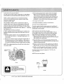
CARURETOR ADJUSTMENT
The idle speed of the engine is adjustable, An idle adjust
ment screw is on the rear side of the carburetor (Fig. 22),
NOTE:Careless adjustments can seriously damage
your unit. An authorized service dealer should make
carburetor adjustments_
CLEAN AtR FILTER
The condition of the air filter is important to the op eration of the unit A dirty or oil saturated air filter wilt
restrict air flow, This is often mistaken for an out of ad justment carburetor. Check the condition of the air filter
before adjusting the idle speed screw. Refer to
Cleaning
Air Filter (p, 13)o
ADJUST IDLE SPEED SCREW
If, after checking the fuel and cleaning the air filter, the
engine still will not idle, adjust the idle speed screw as
follows:
10Start the engine and let it run at a high idle for a min ute to warm upoRefer to StartinglStopping (p. I0)
instructions,
3 If the cutting attachment rotates when the engine
idles, turn the idle speed screw counterclock_wise
1/8 of a turn at a time (as needed), to reduce idle
speed, Checking the fuel, cleaning the air filter, and
adjusting the idle speed should solve most engine
problems, If not and all of the following are true:
- the engine will not idle
• the engine hesitates or stalls on acceleration
.there is a loss of engine power
Check the spark plug for proper gap and condition If
problem still occurs, have the carburetor adjusted by an
authorized service dealer.
REPLACING THE SPARK PLUGS
Use a replacement part number NGKCMR6A.The cor
rect air gap is 0.02 in, (0,5 ram), Remove the plug after
every 25 hours of operation and check its condition°
1.Stop the engine and allow it to cool, Remove the
spark plug cover, Grasp the plug wire firmly and pull
the cap from the spark plug..
2 Release the throttle trigger and let the engine idle If
the engine stops, use a small phillips or fiat blade to
turn the idle speed screw in, clockwise, 118of a turn
at a time (as needed) until the engine idles smoothly
ZClean dirt from around the spark plug Remove the
spark plug from the cylinder head by turning a 5/8 in,
socket counterclockwise°
NOTE:The cutting attachment
the engine idles°
3 Replace cracked, fouled or dirty" spark plug. Set the air
gap at 002 in, (0,5 ram,) using a feeler gauge (Fig 23),
should not rotate when
&install a correctly-gapped spark plug in the cylinder
head,Turn the 518 in. socket clockwise until snug,
Idle Adjustment
Screw
If using a torque wrench torque to: 1IO-120 in, Ib
(12.3-13.,5 N-m)
NOTE: Do not over tighten,
&02 in.
Fig 22
{0,5 ram}
I
WARNING:
DO NOT SAND BLAST_ SCRAPE, OR
CLEAN SPARK PLUG ELECTRODES,
GRIT IN THE ENGINE COULD DAMAGE
THE CYLINDER
Fig,23
,J
14
LEHR]
ALL RIGHTS
RESERVED
2008-2009
TRIMMER
HEADLINEINSTALLATION
SMALL
BUMP
FEED
HEAD
(,,080"
Line)
1 Review
figure
28fornames
ofparts
referred
tointhese
instructions,
8,Continue
windingcord in direction
indicated as
shown, leave about 6 inches free length (15-20 cm)
to pull wire through holes in body. Snap the lines
through top notches in reel (Fig, 26 and Fig.,27)°
2 Lock shaft by inserting allen key into hole in collar and turn
until it engages groove inside, When shaft can no longer
rotate, loosen head byturning it asshown (Fig, 24).
3, Loosen bump feed button and remove by turning CCW
(Fig_25),
Wrap Bottom CCW
Fig 2.7
9, Feed the free ends of
lines through holes in
body while inserting
reel back into body
Hold reel in place
_____Q_J
Body
_1
I I
_-CT-[-_
It!
against spring pres *
sure (Fig_28).
Spr_ng
Reel
._..--.._
Bump
Feed
Button
4-- Nut
Fig,2B
Fig .25
4. Pull reel out of trimmer body, take care to not lose
the spring behind it.,
t0. While holding reel into body, screw bump feed but
ton and nut onto threads by turning CW (Fig, 29).
5_Un-wind and remove the remnants of the line left on
the reelo Note how the ends of the line are hooked in
place and the direction it is wound°
& If using new line from a bulk spool, cut 2 pieces of
line 7..5ft (2°28 m) long. Insert each line into one of
the holes on each retention hook opposite of the
direction of the rotation about1!2 inch deep.
7_
Ftg.29
11..insert allen key into hole tighten by turning body as
shown (Fig, 30)..
Wrap line 180° and wind extra line in the opposite
direction of rotation of the head as shown (Fig.,26),
Retentfon
Hook
Fig, 26
Fig,30
NOTE: Always use original equipment
manufacturer
replacement line, Lines other than those
specified may make the engine overheat or fail.
LEHR I ALL
RIGHT
RESERVED
2008-2009
-
TRIMMER HEAD LINE iNSTALLATION
LARGE BUMP FEEDHEAD (,095" Line)
6oSnapthe free length of linesinto top grooves in reel and pull
through holes on trimmer head body (Fig°34 and Fig.35),
1. Lock shaft by inserting allen key into groove_ Loosen
by turning head as shown for straight shaft,, if your
model is a curved shaft, loosen by turning opposite
the direction shown in (Fig. 3t),.
Trimmer Head
Body
_-----Sp ting
2, Depress tab and twist trimmer head body CWto
disassemble (Fig, 32)_
I
,_-.---- Bump
Feed
Bullon
Trimmer Head Body
Fig35
Bottom
7 Close assembly in sequence as shown in (Fig° 35)°
Rg31
8, Reassemble by lining up the 4 tabs on trimmer head
body and bottom,, Turn CCW until "click" (Fig. 36).
. Tab
Tab *dick"
Top vie___
"_
"Trimmer
Head Body
Fig32
3. If using new line from a bulk spool, cut 2 pieces of
line 7.,5' (2.28 m) long. Insert each line into one of the
holes on each retention hook opposite of the direc tion of the rotation about 1/2 in (12-7 ram) deep
4oWrap line !80 ° and wind extra line in the opposite
direction of rotation of the head (Fig_33)°
Fig 36
9.,Insert allen key into hole, tighten head by turning
as shown for curved shaft and opposite for straight
shaft (Fig, 37).
Retention
Hook
Fig,33
SoWind cord in direction indicated (CW)leaving 6 in (15-20 cm)
access to pull through holes trimmer head body {Fig. 34)°
Fig3 7
Fig 34
_.
16
LEHR I ALL RIGHTS RESERVED 2008-2009
,,J
BRUSH
CUTTER
BLADE
REMOVAL
I INSTALLATION
t Remove
the cotter pin (Fig 38).
GUARD CHANGE
NOTE: When using the brush cutter blade remove
the bottom shield attachment by removing the screw,
Replace when using line trimmer head (Rg 41).
W "_
Screw
CoI_erPin
Cutling At[achment
/
She_ld
Fi.q..38
J
2, Insert an allen key into the hole in the shroud to
lock the shaft° Remove the left-hand thread nut to
dissasemble with tool provided in the tool kit (Fig.39),
_
Attachment
Bottom Shiefd
ROCKER ARM CLEARANCE ADJUSTMENT
This requires partial disassembly of the engine, if you
feel unsure or unqualified to perform this, take the unit
to an authorized service center..
1 Remove the four screws on the engine cover with a
phillips head screw driver (Fig.,42)
2, Remove the engine cover.,
3.. Disconnect the spark plug wire,
Fig,.39
3., Remove in the sequence shown (Fig° 40)
4o Clean dirt from around the spark plug_ Remove the
spark plug by using tool provided, turn CCW
•NOTE: Inspect the valve to rocker arm clearance
a feeler gage after the first 25 hours of operation,
engine must be cold when checking or adjusting
valve clearances. This task should be performed
clean dust free environment,
with
The
the
in a
Clamp Plate_
StarWasher_
Left-HandThreadNut
screws
,=p Enginecover
Fig 40
• For reassembfy, install all components in the correct
sequence ( Fig° 40)°
• Tighten the left-hand thread nut until snug and install
a new cotter pin,
Figo42
LEHR 1ALL RIGHTSRESERVED
2008_2009
ROCKER ARM CLEARANCE ADJUSTMENT
5..Clean dirt from around the rocker arm cover,.
6. Remove the three screws holding the rocker arm
cover with a phillips head screwdriver,
7. Remove the rocker arm cover and gasket (Fig. 43),
Rocker Arm Cover
Screws
FigA3
IF THE CLEARANCE
IS NOT WITHIN SPECIFICATION
1,.Loosen the jam nut and turn the adjusting screw
as necessary.To increase the clearance, turn the
adjusting screw CCW,To decrease the clearance,
turn the adjusting screw CW,,
ZTighten
the jam nut when the clearance is set,
& Recheck the both clearances, Readjust if necessary,
4, Reinstall the rocker arm cover using a new gasket,,
5, Tighten cover screws evenly until snug,
6. Reinstall the engine cover checking the alignment of
the cover,, Tighten the four engine cover screws until
snug,
Rocker Arm
Cover
8..Pull the starter rope slowly to bring the piston to
the top of its travel, (This position is known as top
dead center).Check that the piston is at the top of
its travel by looking down into the spark plug hole..
Both valves should be closed and the rocker arms
• The recommended clearance for both intake and
exhaust is 0 076-&152mm (0003-0 O06in),
• Useastandard automotive 0127ram (O.O05in)feeler gage_
should move freely. If this statement is not true,
repeat this step°
9, Slide a feeler gage between the rocker arm and the
valve return spring. Measure the distance between
the rocker arm and valve stem (Fig,.44) Take care
to only measure the free play.. It is very easy to
insert too thick a feeler gauge and accidentally
depress the valve and spring° Measure both the
intake and exhaust valve distances°
10. Checkthe spark plug and reinstall (See Replacing
the Spark Plug (p.14).,
1I, Reinstall the spark plug wire.
Adjusting
Screws
Jam Nuts
Rocker Arm
Feeler Gauge
Exhaust Valve
FigA4
LEHR 1ALL RIGHTS RESERVED 2008-2009
TO PREVENT SERIOUS INJURY, NEVER PERFORM
MAINrENANOE
OR REPAIRS WITH UNIT RUNNING.
ALWAYS SERVICE AND REPAIR ACOOL UNIT. DISCONNECT THE SPARK PLUG W_RE TO ENSURE THAT THE
UNIT CANNOT START
WARNING:
CLEANING
Useasmallbrush
toclean
theoutside
oftheunit,Do
notusestrongdetergents_
Household
cleaners
that
contain
aromatic
oilssuchaspineandlemon,
andsol
ventssuchaskerosene,
candamage
plastic
housing
or
handle.
Wipeoffanymoisture
withsoftcloth_
LONG TERM STORAGE
STORAGE
. Remove
propane
canister.
•Never
store
theunitwithattached
propane
canister
where
fumes
mayreach
anopen
flame
orsparlc
•Allowthe
engine
tocoolbefore
storing.
•Lock
uptheunittoprevent
unauthorized
useordamage,
. Store
theunitinadpA
welt-ventilated
area.
. Store
unitoutofreach
ofchildren.
NOTE: Remove the spark plug and drain all of the oil
from the cylinder before attempting to start the trimmer
after storage.
3. Change the oil, referring to Changing the Oil (p.13) ..
Dispose of the old oil in accordance to Federal, State
and Local regulations°
TURN
YOOR
UN,T
OFF
A.D
AL' OW
] TO
COOL" O'SERV,O
EYOU
TROUBLE
1 Remove propane canister,,
2. Allow the engine to cool Remove the spark pkJg and
put 5 drops of high quality motor oil into the cylinder_
Pull the starter rope slowly to distribute [he oil., Rein stall the spark plug
4..Thoroughly clean the unit and inspect for any loose
or damaged parts, Repair or replace damaged parts
and tighten loose screws, nuts or bohs The unit is
ready for storage.,
TRANSPORTING
• Allow the engine to cool before transporting,
• Secure the unit while transporting
• Remove propane canister.
SHOOTING
ENGINE WILL NOT START
CAUSE
ACTION
EMPTY PROPANE
CANISTER
INSTALL
REPLACE
BAD SPARK PLUG
FULL CANISTER
THE SPARK PLUG
ENGINE WILL NOT IDLE
CAUSE
ACTION
AIR FILTER IS PLUGGED
REPLACE
IMPROPER
CARBURETOR
ADJUSTMENT
THE AIR FILTER
ADJUST ACCORDING TO THE 'CARBURETOR
ADJUSTMENTS' SECTION OR TAKE TO AN
AUTHORIZED SERVICE DEALER FOR AN ADJUSTMENT
ENGINE WILL NOT ACCELERATE
CAUSE
CUTTING
ACTION
ATTACHMENT
BOUND WITH GRASS
DIRTY AIR FILTER
STOP ENGINE AND CLEAN THE CUTTING ATTACHMENT
CLEAN OR REPLACE THE AIR FILTER
ENGINE LACKS POWER OR STALLS WHEN CUTTING
CAUSE
ACTION
BAD SPARK PLUG
IF FURTHER ASSISTANCE IS REQUIRED, CONTACT A QUALIFIED SERVICE DEALER
\
LEHR 1ALL RIGHTS RESERVED 2008_2009
19
ENGINE*
ENGINE TYPE
AIR COOLED
4-CYCLE
2&4 CC
DISPLACEMENT
CENTRIFUGAL
CLUTCH TYPE
OPERATING
R.PM,,
IDLE SPEED
6,800-9300
RoPM.
3,000-3,400
R, P.M,
ELECTRONIC
IGNITION
TYPE
IGNITION
SWITCH
PUSH ON/OFF SWITCH
VALVE CLEARANCE
0,,076-0.,152MM
SPARK PLUG GAP
(0,,003_0o006 IN)
0,,020 INCH (&5 MM)
SAE 10W-30 OIL
LUBRICATION
CRANKCASE
OIL CAPACITY
1.7 FLUIDO7
FUEL
PROPANE l&40z
CARBURETOR
CHOKELESS
MUFFLER
SAFETY LOCK WITH MANUAL SPRING RETURN
SHAFT
AND
HOUSING
ALUMINUM
DRIVE SHAFT HOUSING
CONTROL
APPROXIMATE
CUTTING
LINE SPOOL
CUTTING
UNIT WEIGHT
13,,1-14,9 LBS
BUMP FEED CUTTING HEAD
2.4/3o4 INCHES
DIAMETER
0,080/&095
LINE DIAMETER
PATH DIAMETER
ALL SPECIFICATIONS
ARE BASED
THE
ON THE
LAS7EST
RIGHT TO MAKE
PRODUCT
CHANGES
INFORMATION
AT THE TIME OF PRINTING
AT ANY TIME WITHOUT
NOTICE
......
LEHR]
INCHES
17 INCHES (431 o8MM)
WE RESERVE
2O
TUBE
FINGER -TIP TRIGGER
MECHANISM
TRIMMING
ALL-POSITION
BAFFLED WITH GUARD
THROTTLE
THROTTLE
CANISTER
AUTO REWl N D
STARTER
DRIVE
(50mL)
ALL RIGHTS
RESERVES
2008-2009
,
,,,, ,,,,,J
The limited warranty set forth below is g_ven by EH Rwith respect to new merchan
dlse purchased and used tn the Untied States and Canada, Its possessions and
t erritorieS_
LEHR warrants to the original purchaser that each new LEHR brand power tool or
attachment Is free from defe_s in material and workmanship and agrees to repair or
replace und_
this warranty any defective
power product or attachmeot
as follOws
from the original date of purchase
3 yF_
- Part_ and Labor, on carburetor.
(a)The wa_anty period begins on the datethe engine or equipment Isdeliveredto an
ultimate purchasL_
(h)General
EmlssionsWarrantyCoverage
engine or equipment
musl warrant
purposes.
Improper handling_ improper maintenance, or the use of accessories and!or attachments not specifically recommended
by LEHR for this produ_ In addition, it does not
Any warranted
to misuse- neglect, negligence,
plugs, carburetor adjustments_ filters, curing Bne, bump knobs outer spools, Inner
reels, stoner pulley, or rotating heed parts that will wear and require replacement with
reasonable use during the warranty period This warranty does not cover pre delivery
setup or normal adjustment.s explained In the instruction manual.
THIS WARRA NTY GIVE5 YOU SP ECIFIC L EG AL RIGHTS, A ND YOU MAY HAVE
HICH VARY FROM STAT ETOSTAT
E STAT E$ DO NOT ALLOW UMFrATIO NS O N HOW
LONG AN iMPLIED WARRA NTY LASTS OR T HE EXCLUSIO N OR UMITATtO N5 OF
iNCIDENTAL OR CO NS EQU ENTIAL DAMAGE S, SO T HE ABe VE LIMITATIONS OR
EXCLUSIO N MAY NOT APPLY TO YOU
LEHR does not extend any warranty for products so_d or exported outside of the
United States or Canada, its possessions and territories, except those said through
channels of exporl distribution,
time without notice or obligationto any purchaser
HOWTO OBTAIN SERVICE: Warranty service is available
TheCalifomia
ProtecttonAgencyand
Aft ResourcesBoard_the
Environmental
pan fails during
the period of warranty
coverage,
it mus_ be repaired
or replaced
by the manufacturc_ according to Subsection (4} below Any such part repaired c¢
replaced under the warranty must be warranted for the remaining warranty period,
Any warranted part that is scheduled only for regular inspection in the wrtrten Instrue
tlons required by Subse_ton (d) most be warranted for the warranty period defined
(bit2)
A statement
in such wrilt en Instructions
to the effe_.'1,of "repair
or _'eptace as necessary _will not reduce the period ofwarranty coverage Any
sud_ part repaired or replaced under warranty must be warranted for the remaining
warranty period.
Any warranted part that ts scheduled for replacement as required maintenance inthe
written Instructions required by Subsection (d) mu_ bewan_anted for the period of
time prior to the first scheduled replacement point for that part I[ the par_ faH,_prior
to the first scheduled replacement, the part must be repaired or replaced by the
engine manufacturer
accordlng to Subsection
(4) below
Section 4: Any such part repaired or replaced under wan'only must be warranted for
the remainder of the period prior 1o the first scheduled replacement point for the
performed
of any warranted
part under the war_anty must be
at no charge to the owner at a warranty station
service the subject engtne_
EHF_
the emissions control system's warranty on your 2009 aod
standards.LEHP_ lnc must wan'ant the emissions controlsystem
on your small off-road engloe for the period listed below provided there has been no
abuse, neglect or improper maintenance of your equipment
Your emissions control
_y_.em may include
(d]Must be warranted forthe waTranly period definedIn Subsection(bit2}Irony such
Notwithstanding
the provisions of Subse_ion (4) above, warranty services or repairs
must be provided at all manufaLlorer
distribution ceme_ that are franchised to
later small off-road engine. ]n California and the 49 stales, new equipment
that use
small off-roadengines must he designed,built,
and equipped to meet the State's
anti-smog
in
service dealer, To locate the dealer _nyour area., visit our
or wrtteto
stringent
maintenance
required by Subsection
par_ Repair or replacement
with proof of purchase
webslte at ww'w.golehccom or ceil t -866-941*LEHR
B922 FJttsAve, LA, CA 90034.
YOUR WARRANTY
RIGHTS AND OBLIGATIONS
Inc are pleased to explain
the wrirt _n instructions
The policy of LEHR ls In cominu-
oUsly Improve its products, Therefore LEH Rreserves the right to change, modf[y, or
dfscontinue models, designs, specifications, and accessories of all products at any
through your local authorized
as foBows:
part that Is not scheduled for replacement as required
in Subsection
E
NO CLAIMS FOR CO NS EQU ENTiAL OR aT HER DAMAGE $ WiLL B E ALLOW ED,
ANDTHERE AR E NO aT HER EXPRESS WARRA t'-mE5 EXCEFq'THO$ E EXPRESSLY
STIPULAT ED HERE1N. tOM
part for a period of two years,
pans will be Interpreted
or accident,
or has been operated In any way contraPi to the operating instructions specified in
this operator's manual= Additionally, this warranty does not cover tune-ups, spark
LEHWsauthorized
is:
manshtp that causes the failure ofa warranted
(c) The warranty on emisslons.related
cover any product that has been subject
ofeachsmalloff_roed
purchaser and each subsequent
Destgned_ buil_, and equipped so as to conform with all applicable regulations
adopted by the Air Resources Board; an d free from defects Inmaterials and work -
30 DAY5 - Parts and Labor, if used for rentaI purposeS.
This warranty is not transferable and does not cover damage or liability caused by
OTHERBIGHTSW
The manufacturer
to the ultimate
Owner that the engine Or equipment
2 YF_FL_ - Parts and Labor_when used for household purposes.
90 DAYS - Parts and Labor, when used for commercial professional, or Income
predating
DEFECTS WARRANTY REQUIREMENTS:
parts such a._ _rburetors
or fuel Injection
system, ignition
system, catal_ic converters, fuel tank_, valves, filters_ clamps, conneGors, and other
assodated components.
_so, included may be hoses, belts, connecto_, sensors,
and other emlsslon-related
assemblies. Were a warrantable condition exists, L EHR
will repair your small off*road engine at no cost to you Ioctudlng diagnosis+ pans and
labor at an a_hodzed
service dealer.
MANUFACTUBE_S WARRANTY GOVERAG_
Thfs emissions control system is warranted
for two years. If any emissions-related
part on your equipment is defe_tve0 the pan wlll be repaired or replaced by _HR.
OWNER'S WARRAF_(
RESPONSIBILmES:
ASthe small off-road engine owner, you are responsible for pedormance of the required maintenance Rsted tn your owner's manual I£H Rrecommends that you retaln
oil receipts covering maintenance on your small off-road engine, but _H Rcann_
deny warranty solelyforthe lackofreceiptsoryour fallure
to
ensure the performance of all scheduled
maintenance.
As the small off-road engine
owner,, you should however be awarethat LEHR may denyyou warranty coverage
if your smafl off-road engine o_ a part has failed due to abuse, neglect, or improper
maintenance or unapproved
modifications.
You are responsible for presenting your smelt off-road
engine to a LEHRservice
center as soon as the problem exists, The warranty repairs should be completed ina
reasonableamount oftlme,,
no_ to exceed 30 days, Ifyou have a que_ion regarding
your warranty coverage, you should contact LEHR at l-B66*94%L
EH_
The owner must not be charged for diagnostic
'[hat a warranted
performed
at a warranty
The manufacturer
labor that leads to the determination
part Is in fact defective, provided that such diagnosllc work is
_atlon,
ts liable for damages
to other engine components
proximately
caused by a failure onder warranty of any warranted part
Throughout the emissions warranty period defined in Subsection (b)(2), the menu
lecturermust main_n a supply ofwarranted partssufficient
to meet the exposed
demand fo_ soch parrs
Any replacement part may be osed in the performance
of any warranty maintenance
or repairs and must be provided without charge to the owner Such use will not
reduce the warranty obligations of the manufacturer
Add,_n or modihed pans thalare not exempted
be used. The use of any non_xempled
bythe AirResources Board may not
add-on or modlhed
parts will be grounds
for disallowing a warranty claim The manufacturer
will not be liable to warrant
failures of warranted panelscaused by the use of a non-exempted add-on or modified pan.
The manufacturer
manufacturer's
Issuing the warranty shall provide any documents that describe thai
warranty procedures or policies within five working days of request
bythe Air Resources Board
(d) Emission Warranty
The following
Pa_
componen_
List
are Included
tn the eml_ion
related warranty
Air Filter, Co,bur eto_, Regulator_ Fuel Unes & Fl_lngs. Fuel Valve, Ignition
Plug_ Valves, CAM and Muffler
LEH Rwill furnish with each now engine written instructions
of the engine:.
Colt_Spark
for the maintenance
and
use of the engine by the owne_
LEHR 1ALL RIGHTS RESERVED 2008-2009
21
J
22
LEHRI ALLRIGHT
RESERVED
2008-2009