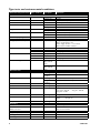
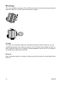
1
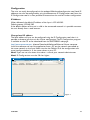
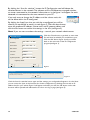
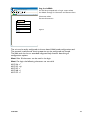
6640-2001
Lynx
SERIES
Industrial Ethernet
8-port Switch
www.westermo.com
© Westermo Teleindustri AB
User Guide
Legal information
The contents of this document are provided “as is”. Except as required by applicable
law, no warranties of any kind, either express or implied, including, but not limited to,
the implied warranties of merchantability and fitness for a particular purpose, are made
in relation to the accuracy and reliability or contents of this document. Westermo
reserves the right to revise this document or withdraw it at any time without prior
notice.
Under no circumstances shall Westermo be responsible for any loss of data or income
or any special, incidental, and consequential or indirect damages howsoever caused.
More information about Westermo can be found at the following Internet address:
http://www.westermo.com
2
6640-2001
Safety
!
Before installation:
Read this manual completely and gather all information on the unit. Make sure
that you understand it fully. Check that your application does not exceed the safe
operating specifications for this unit.
This unit should only be installed by qualified personnel.
This unit should be built-in to an apparatus cabinet, or similar, where access is
restricted to service personnel only.
The power supply wiring must be sufficiently fused, and if necessary it must be
possible to disconnect manually from the power supply. Ensure compliance to
national installation regulations.
This unit uses convection cooling. To avoid obstructing the airflow around the unit,
follow the spacing recommendations (see Cooling section).
!
Before mounting, using or removing this unit:
Prevent access to hazardous voltage by disconnecting the unit from power supply.
Warning! Do not open connected unit. Hazardous voltage may occur within this
unit when connected to power supply.
!
Class 1 Laser Product
Do not look directly into fibre optical fibre port or any connected fibre although
this unit is designed to meet the Class 1 Laser regulations.
Care recommendations
Follow the care recommendations below to maintain full operation of unit and to fulfil
the warranty obligations.
This unit must not be operating with removed covers or lids.
Do not attempt to disassemble the unit. There are no user serviceable parts inside.
Do not drop, knock or shake the unit, rough handling above the specification may cause
damage to internal circuit boards.
Do not use harsh chemicals, cleaning solvents or strong detergents to clean the unit.
Do not paint the unit. Paint can clog the unit and prevent proper operation.
Do not expose the unit to any kind of liquids (rain, beverages, etc). The unit is not waterproof. Keep the unit within the specified humidity levels.
Do not use or store the unit in dusty, dirty areas, connectors as well as other mechanical
part may be damaged.
If the unit is not working properly, contact the place of purchase, nearest Westermo distributor office or Westermo Tech support.
Fibre connectors are supplied with plugs to avoid contamination inside the optical port.
As long as no optical fibre is mounted on the connector, e.g. for storage, service or
transportation, should the plug be applied.
6640-2001
3
Note. Fibre Optic Handling
Fibre optic equipment needs special treatment. It is very sensitive to dust and dirt. If
the fibre will be disconnected from the modem the protective hood on the transmitter/
receiver must be connected. The protective hood must be kept on during transportation.
The fibre optic cable must also be handle the same way.
If this recommendation not will be followed it can jeopardise the warranty.
Cleaning of the optical connectors
In the event of contamination, the optical connectors should be cleaned by the use of
forced nitrogen and some kind of cleaning stick.
Recommended cleaning fluids:
• Methyl-, ethyl-, isopropyl- or isobutyl-alcohol
• Hexane
• Naphtha
Maintenance
No maintenance is required, as long as the unit is used as intended within the specified
conditions.
Agency approvals and standards compliance
Type
Approval / Compliance
EMC
EN 61000-6-2, Immunity industrial environments
EN 55024, Immunity IT equipment
EN 61000-6-3, Emission residential environments
FCC part 15 Class B
EN 50121-4, Railway signalling and telecommunications apparatus
IEC 62236-4, Railway signalling and telecommunications apparatus
Safety
EN 60950-1, IT equipment
FCC Part 15.105 Notice:
4
This equipment has been tested and found to comply with the limits for a
Class B digital device, pursuant to Part 15 of the FCC Rules. These limits
are designed to provide reasonable protection against harmful interference
in a residential installation. This equipment generates, uses and can radiate
radio frequency energy and, if not installed and used in accordance with
the instructions, may cause harmful interference to radio communications.
However, there is no guarantee that interference will not occur in a particular installation. If this equipment does cause harmful interference to radio
or television reception, which can be determined by turning the equipment
off and on, the user is encouraged to try to correct the interference by
one or more of the following measures:
… Reorient or relocate the receiving antenna
… Increase the separation between the equipment and receiver
… Connect the equipment into an outlet on a circuit different from that to
which the receiver is connected
… Consult the dealer or an experienced radio/TV technician for help.
6640-2001
Declaration of Conformity
CE Certificate of Conformity
Westermo OnTime AS declares that the listed products conform to the Council Directives and standards:
73/23/EEG Low Voltage Directive (LVD)
89/336/EEG Electromagnetic Compatibility (EMC –directive)
EN 61000-2
EN 61000-6-2
EN 61000-6-4
EN 50121-4
EN 50121-3-2
EN 50155-1
EN 50155-2
EN 50155-3
EN 50155-4
EN 50155-5
(except conducted measurement values)
all temperature classes
MTBF >180.000 hrs at 55°C (MIL2.17)
chap. 5.1:OnTime Quality Manual after ISO9001:2000 principles
chap. 5.3: not conforming according to ISO 9002
EN 50155-6
EN 50155-7
chap. 7.7: With protective coating
chap. 7.9: With wall mounting brackets
EN 50155-8
chap. 8.2: not conforming
EN 50155-9
defined documents available for customer after signing of Non-DisclosureAgreement
EN 50155-10 chap. 10.2.11: With wall mounting brackets
IEC 60945, 8.7 Sinusoidal vibration
IEC 60068-2-6 test Fc
IEC 60068-2-64 tests Fh
IEC 60068-2-27 tests Ea
IEC 60068-2-29 tests Eb
IEC 60068-2-30 test Db
IEC 68-2-2 test Bd
Dry Heat
Type of Equipment:
Industrial Ethernet Switches
Models:
U208, R208, T208 all versions,
Lynx series
Reference:
U/R/T200 Operator Manual, Lynx Operator Manual
U/R/T200 Install Guide, Lynx Install Guide
Øyvind Holmeide, sign.
Managing Director
March 27th, 2006
Westermo OnTime AS,
Gladsvei 20, 0489 Oslo, Norway
Tel +47 22090303
Fax +47 22090310
6640-2001
Corp. identity number 981 567 560
www.ontimenet.com
e-mail: [email protected]
5
Type tests and environmental conditions
Environmental phenomena Basic standard
EMC
ESD
EN 61000-4-2
Description
Test levels
Power frequency magnetic field EN 61000-4-8
Pulse magnetic field
EN 61000-4-9
Voltage dips and interruption
EN 61000-4-29
Enclosure contact
Enclosure air
Enclosure
Enclosure
Signal ports
Power ports
Signal ports
Power ports
Signal ports
Power ports
Enclosure
Enclosure
DC power ports
Radiated emission
Enclosure
± 6 kV
± 8 kV
20 V/m 80% AM (1 kHz), 80 – 2 000 MHz
20 V/m pulse modulated 200 Hz, 900 ± 5 MHz
± 2 kV
± 2 kV
± 2 kV line to earth, ± 2 kV potential difference
± 2 kV line to earth, ± 2 kV line to line
10 V 80% AM (1 kHz), 0.15 – 80 MHz
10 V 80% AM (1 kHz), 0.15 – 80 MHz
1000 A/m, 50 Hz
300 A/m
Voltage interruption - 3 x 30 s within 5 minutes: 19V to 0 V & 62.4 V to 0V Power supply variation - 3 x 1 minute 30% increase and 25% reduction
Class B
Class B
Complying with the limit line
Class B
Class B
Complying with the limit line
1.5 kVrms 50 Hz 1 min
RF field AM modulated
RF field 900 MHz
Fast transient
IEC 61000-4-3
ENV 50204
EN 61000-4-4
Surge
EN 61000-4-5
RF conducted
EN 61000-4-6
Conducted emission
Dielectric strength
EN 55022
FCC part 15
IEC 60945
EN 55022
EN 55022
IEC 60945
EN 60950-1
Environmental
Temperature
Signal ports
DC power ports
Signal port to
other isolated
ports
Power port to
other isolated
ports
1.5 kVrms 50 Hz 1 min
Altitude
Service life
Vibration
IEC 60068-2-6
Operating
Storage &
Transport
Operating
Storage &
Transport
Operating
Operating
Operating
IEC 60068-2-64
IEC 60068-2-27
Operating
Operating
0.23 g, 3 – 2000 Hz
Shock
Bump
IEC 60068-2-29
Operating
2 g, 11ms
UL 94
Aluminium
IEC 529
Enclosure
Flammability class V-1
52.5 x 100 x 101 mm 52.5 x 119 x 101 mm
0.6 kg
IP 40
Convection
Horizontal on 35 mm DIN-rail
Humidity
Packaging
Enclosure
Dimension W x H x D With connectors
Weight
Degree of protection
Cooling
Mounting
6
–40 to +70ºC
–50 to + 85ºC
5 to 95% relative humidity
5 to 95% relative humidity
2 000 m / 70 kPa
10 year
1 mm, 3 – 13.2 Hz 0.7 g, 13.2 – 100 Hz 1.5 g, 5.5 – 30 Hz
0.42 mm, 30 – 50 Hz 4.2 g, 50 – 500 Hz
All directions: 2 g, 11 ms
Z-axis:
30 g, 11 ms
6640-2001
Description
Lynx is a range of switches consisting of three different function levels and four different
type approvals, giving you the ability to select the perfect switch for your application providing optimum functionality at the best value.
Our unique FRNT (Fast Recovery of Network Topology) technology is the fastest protocol on the market to re-configure a network in the event of any failure of a link or hardware. That is why the Lynx-series is used in safety critical applications such as tunnels,
traffic signal control and railway systems.
Installations in harsh environments and places with heavy electrical interference demand
the use of a reliable media. The Lynx-series provides a number of solutions using fibre
optic transceivers. Multi- or singlemode transceivers can be used to build point-to-point
or redundant ring networks with ranges up to 120 km between each switch. Our BIDI
transceiver, which transmits and receives data on a single fibre can be used in applications
where the number of fibre cores is limited.
Real-time properties are implemented in the Lynx-series in order to achieve determinism
for real time critical applications. The Lynx-switches supports QoS (Quality of Service)
with four priority queues and strict priority scheduling as well as HoL (Head of Line
Blocking Prevention). All to assure that the data network is deterministic.
6640-2001
7
Interface specifications
Power
Operating voltage
Rated current
Rated frequency
Inrush current, I2t
Startup current*
Polarity
Redundant power input
Isolation to
Connection
Connector size
Shielded cable
19 to 60 VDC
146 mA @ 24 VDC 80 mA @ 48 VDC
DC
49·10-4 A2s @ 48 VDC
250 mA @ 24 VDC
Reverse polarity protected
Yes
All other
Detachable screw terminal
0.2 – 2.5 mm2 (AWG 24 – 12)
Not required
* External supply current capability for proper startup
Ethernet TX
Electrical specification
Data rate
Duplex
Circuit type
Transmission range
Isolation to
Connection
Shielded cable
Conductive housing
Number of ports
8
IEEE std 802.3. 2000 Edition
10 Mbit/s, 100 Mbit/s, manual or auto
Full or half, manual or auto
SELV
150 m, according to long cable specification
Power
TX connectors: RJ-45 shielded, auto MDI/MDI-X
Not required, except when installed in Railway applications as
signalling and telecommunications apparatus and located close
to rails.
Isolated to all other circuits
6
6640-2001
Ethernet SFP pluggable connections (FX or TX)
Electrical specification
IEEE std 802.3. 2000 Edition
Data rate
100 Mbit/s, 1000 Mbit/s manual or auto
Duplex
Full or half, manual or auto
Circuit type
SELV
Transmission range
Depending on tranceiver
Isolation to
Power
Connection
TX connectors: RJ-45 shielded, auto MDI/MDI-X FX connectors: LC
Shielded cable
Not required
Conductive housing
Isolated to all other circuits
Number of ports
1 or 2
Status relay
Contact resistance
Isolation to
Connection
Connector size
6640-2001
25 Ω
1500 VDC
Detachable screw terminal
0.2 – 2.5 mm2 (AWG 24 – 12)
9
Optical Power Budget
The allowed link length is calculated from the optical power budget (OPB), the available optical
power for a fibre-optic link, and the attenuation of the fibre, comprising losses due to in-line connectors, splices, optical switches and a margin for link ageing (typical 1.5 dB for 1300 nm).
The worst-case optical power budget (OPB) in dB for a fibre-optic link is determined by the difference between the transmitter’s output optical power (min) and the receiver input sensitivity (max).
FX (Fibre)
Fibre connector
Fibre type
SM-LC80
LC duplex
Singlemode 9/125 mm
SM-LC40
LC duplex
Singlemode 9/125 mm
SM-LC15
LC duplex
Singlemode 9/125 mm
Wavelength
Transmitter Output optical power min/max
Receiver Input sensitivity, max
Receiver Input optical power, max
Optical power budget, worst-case
Transceiver type
1550 nm
–5/0 dBm**
1310 nm
–5/0 dBm**
1310 nm
–15/–8 dBm**
MM-LC2
LC duplex
Multimode,
62.5/125 and
50/125 mm
1310 nm
–20/–14 dBm*
–34 dBm
–34 dBm
–31 dBm
–31 dBm
–5 dBm***
–3 dBm***
–8 dBm
–8 dBm
29 dB
29 dB
16 dB
11 dB
Laser class
FX (Fibre)
Fibre connector
Fibre type
Wavelength nm, connector 1 Wavelength nm, connector 2
Transmitter Output optical power min/max
Receiver Input sensitivity, max
Receiver Input optical power, max
Optical power budget, worst-case
Transceiver type
Laser class
*
**
***
10
Small Form Factor Pluggable (SFP) Multi-Sourcing Agreement (MSA) compliant
Class 1, IEC 825-1 Accessible Emission Limit (AEL)
Bi-di LC-60
LC Simplex
Singlemode 9/125 μm
Bi-di LC-40
LC Simplex
Singlemode 9/125 μm
Bi-di LC-20
LC Simplex
Singlemode 9/125 μm
Tx 1310, rx
1550 Tx 1550,
rx 1310
–5/0 dBm **
Tx 1310, rx
1550 Tx 1550,
rx 1310
–8/0 dBm **
Tx1310, rx
1550 TX
1550, rx 1310
-10/0 dBm **
Bi-di MM LC-2
LC Simplex
Multimode 62.5/125 and
50/125 μm
Tx 1310, rx
1550 Tx 1550,
rx 1310
–10/–8 dBm *
–34 dBm
–34 dBm
–28 dBm
–28 dBm
0 dBm***
0 dBm***
0 dBm
–0 dBm
29 dB
26 dB
18 dB
18 dB
Small Form Factor Pluggable (SFP) Multi-Sourcing Agreement (MSA) compliant
Class 1, IEC 825-1 Accessible Emission Limit (AEL)
Output power is power coupled into a 62.5/125 mm multimode fibre
Output power is power coupled into a 9/125 mm singlemode fibre
The optical power should be reduced by at least 5 dB (SM-LC80 and Bi-di LC-60) or 3dB (SM-LC-40 and Bi-di LC-40) between the optical output and input.
6640-2001
Location of interface ports and LED’s
LED Indicators (for details see page 12)
Power, screw terminal (for details see below)
FX(Fibre) (for details see page 10)
Ethernet connection TX (6 ports)
Contact Signale Direction Description
No.1
TD+
In/Out
Transmitted/Received data
No. 2
TD–
In/Out
Transmitted/Received data
No. 3
RD+
In/Out
Transmitted/Received data
No. 4
–
No. 5
–
No. 6
RD–
No. 7
–
Not Connected
No. 8
–
Not Connected
Not Connected
Not Connected
In/Out
Shield
Fault contact (for details see below)
HF-connected
NOTE! Railway installation close to the rails.
For a cable located inside 3 m boundary and connected to this
port, the use of shielded cable is recommended, this is to minimise the risk of interference. The cable shield should be properly connected (360°) to an earthing point within 1 m from
this port. This earthing point should have a low impedance connection to the conductive enclosure of the apparatus cabinet,
or similar, where the unit is built-in. This conductive enclosure
should be connected to the earthing system of an installation
and may be directly connected to the protective earth.
L1407F1MM-SX-LC550
-COM
Lynx
3640-4030
-COM
MAC:
00:07:7c:80:24:ae
Serial no:
lx4232
+DC2
+DC1
Westermo
Teleindustri
www.westermo.com
Input voltage:
19-60VDC max 7W
Date of mfg (Y/M/D):
2006-10-17
Power connection screw terminal
Transmitted/Received data
The Lynx series supports redundant
power connection. The positive inputs
are +DC1 and +DC2, the negative input
for both supplies is –COM. Connect
the primary voltage (e.g. +24 VDC) to
the +DC1 pin and ground to one of the
–COM pins on the power input on the
Lynx switch by using the enclosed power.
6640-2001
lx003967
Country of origin:
Sweden
www.westermo.com
Common
Status -
No. 4
Status +
Common
Digital in +
+DC2
No. 3
Westermo Teleindustri AB
SE-640 40 Stora Sundby
Sweden
+DC1
No. 2
Digital in -
No. 1
Westermo
Description
Laser Class 1 Product
Fault contact
4-position
4-position
Description
No. 1
Alarm relay (status) +
No. 2
Alarm relay (status) –
No. 3
–
No. 4
–
11
LED indicators
LED
Status
On
OFF
Unit has no power
GREEN
Internal power ok
FLASH
DC1
RED
GREEN
DC2
Connected to IP Configuration tool
Unit has no power on +DC1
OFF
Unit is unconnected
Unit has no power on +DC2
Internal DC2 power is ok
OFF
Unit is unconnected
OFF
FRNT is not enabled or not supported
GREEN
FRNT is running and the switch is configured as member switch in the ring.
GREEN FLASH FRNT is running and the switch is configured as Focal Point
RED
ST 1
GREEN
ST 2
NC
1 to 8
OFF
GREEN
ON
DC 2
8
FRNT
ST 1
ST 2
7
Internal DC1 power is ok
RED
GREEN
FRNT
Initialisation progressing
DC 1
6
Lynx
RED
Description
5
4
3
2
1
FRNT Error
Indicates STP root
No Link
Good link
GREEN FLASH Data is transmitted
YELLOW OFF
YELLOW ON
12
Port larm and no linkIf RSTP mode
port is blocked
6640-2001
Configuration
The units can easily be configured via the onboard Web based configuration tool. Local IP
addresses can also be configured by using the Westernmo IP Configuration tool, from the
IP Configuration tool it is then possible to browse into the unit for further configuration.
IP Address
When delivered, the default IP address of the Lynx is 192.168.2.85. Default gateway 192.168.2.85 If the default address of the unit is valid in the connected network it is possible to access
the unit directly from a web browser.
Change local IP address
The local address of Lynx can be configured using the IP Configuration tool, then it is
possible to browse into the unit for further configuration. The IP Configuration program
is available on the CD or for download from the WESTERMO web page: http://www.westermo.com, (choose Downloads/Software/Ethernet/ Name: setup.exe Install the software and start the application from a PC on the network connected to the same network as the Lynx. Make sure that the Default IP of the configuration software (see figure below) is in the same subnet as your PC.
Note! If you are not sure about the subnet – consult your network administrator.
Note! IP Config version must be 9.8.4 or higher.
IP configuration
Default IP: 192. 168. 2. 85
Device list:
IP Adress
192.168.2.85
Subnet Mask
255.255.255.0
Scan for switches
6640-2001
MAC Adress
00-07-7C-80-4A-6C
SW Ver
9.74
Mask: 255. 255. 255.
Type
Lynx
0
Help
About
Status
Close
Figure 1
13
By clicking the “Scan for switches” button the IP Configuration tool will detect the
switches/routers in the network. The software will list all Westermo managed switches
or routers connected to the network. Information as in the figure 1 will appear for each
detected unit connected to the same network as your PC.
IP configuration
If you only want to change the IP address and the subnet mask, this can be done within the IP config tool.
By clicking the listed Lynx that you wish be re-configured you will be Figure 2
asked if you would like to access via web figure 2. Click the abort button, enter the preferred IP address, Subnet mask and IP gateway address and click the Set button to confirm the settings in the unit (see figure 3).
Note! If you are not sure about the settings – consult your network administrator.
Access switch via web?
OK
Click the Close button to get back to main view.
You will then be asked if you would like to quit.
Click the OK button, figure 4, and you will be
back to the main view of the IP Configuration
program(see figure 1).
Selected Device
Lynx configuration
IP adress:
192
168
2
200
Subnet mask:
255
255
255
0
MAC adress:
00 07
Host name:
Westermo
Location:
location
IP gateway adress:
192
Cancel
7C 80 4A 6C
168
2
200
IP gateway adress:
Set
Close
Figure 3
IP configuration
You have set new parameters on the switch. The switch must be restarted in order for the new parameters to take effect (except IP address change). Type cancel to return to
selected dialog or OK if you still want to quit.
OK
Cancel
Figure 4
Click the Scan for switches button again and the settings you configured will appear in the list. Now
you can access the Lynx via the browser for further configuration by clicking the unit with an IP
address that fits your subnet. Figure 2 will appear and when you click the OK button and a web
browser will be opened and redirected to the Lunx unit log in page (see figure 5).
14
6640-2001
Westermo - location - Provided by Westermo UK
http://192.168.2.200/conf/p.cgi
File
Edit
View
Favorites
Tools
Westermo - location
Help
Log in via Web
Google
You will be prompted with a Login screen where the default settings for Username and Password are:
Home
Feeds (J)
Print
Page
Tools
Username: admin
Password: westermo
Login
Username:
Password:
Login
Figure 5
Done
Internet
The unit can be easily configured via the on-board Web based configuration tool. The network interface and switch properties can be configured and stored. The Web tool also has an extended integrated help function describing all configuration options.
Note! Max 10 characters can be used in the login.
Note! For login the following characters are not valid. ASCII 34 = "
ASCII 35 = #
ASCII 39 = ’’
ASCII 40 = (
ASCII 92 = \
6640-2001
15
Mounting
This unit should be mounted on 35 mm DIN-rail, which is horizontally mounted inside an
apparatus cabinet, or similar. Snap on mounting, see figure.
Cooling
This unit uses convection cooling. To avoid obstructing the airflow around the unit, use
the following spacing rules. Minimum spacing 25 mm (1.0 inch) above /below and 10 mm
(0.4 inches) left /right the unit. Spacing is recommended for the use of unit in full operating temperature range and service life.
Removal
Press the device upwards to compress locking spring, tilt forward to unhook device from
DIN-rail.
16
6640-2001
Westermo Teleindustri AB • SE-640 40 Stora Sundby, Sweden
Phone +46 16 42 80 00 Fax +46 16 42 80 01 E-mail: [email protected] Westermo Web site: www.westermo.com
Westermo Data Communications AB Svalgången 1 SE-724 81 Västerås Phone: +46 (0)16 42 80 00 • Fax: +46 (0)21 35 18 50 [email protected]
Westermo OnTime AS Gladsvei 20 0489 Oslo, Norway Phone +47 22 09 03 03 • Fax +47 22 09 03 10 E-mail: [email protected]
Westermo Data Communications Ltd Talisman Business Centre • Duncan Road Park Gate, Southampton • SO31 7GA Phone: +44(0)1489 580‑585 • Fax.:+44(0)1489 580586 E-Mail: [email protected]
Westermo Data Communications GmbH Goethestraße 67, 68753 Waghäusel Tel.: +49(0)7254-95400-0 • Fax.:+49(0)7254-95400-9 E-Mail: [email protected] Westermo Data Communications S.A.R.L. 9 Chemin de Chilly 91160 CHAMPLAN Tél : +33 1 69 10 21 00 • Fax : +33 1 69 10 21 01 E-mail : [email protected]
Westermo Data Communications Pte Ltd 2 Soon Wing Road #08-05 Soon Wing Industrial Building Singapore 347893 Phone +65 6743 9801 • Fax +65 6745 0670 E-mail: [email protected] Westermo Teleindustri AB have distributors in several countries, contact us for further information.
REV.B 6640-2001 2008.08 Mälartryck AB, Eskilstuna, Sweden
Subsidiaries