1
®
Setup Guide
The Printronix P5000 series with DEC LG Emulation
The Printronix P5000 series with DEC LG Emulation
Setup Guide
®
172292-001, Rev B
Trademark Acknowledgments
Trademark Acknowledgments
ANSI is a registered trademark of American National Standards Institute, Inc.
Code V is a trademark of Quality Micro Systems.
Chatillon is a trademark of John Chatillon & Sons, Inc.
ENERGY STAR® is a registered trademark of the United States
Environmental Protection Agency. As an ENERGY STAR® Partner,
Printronix has determined that this product meets the ENERGY STAR®
guidelines for energy efficiency.
Ethernet is a trademark of Xerox Corporation.
IBM is a registered trademark of International Business Machines
Corporation.
IGP is a registered trademark of Printronix, Inc.
Intelligent Printer Data Stream and IPDS are trademarks of International
Business Machines Corporation.
LinePrinter Plus is a registered trademark of Printronix, Inc.
MS-DOS is a registered trademark of Microsoft Corporation.
PC-DOS is a trademark of International Business Machines Corporation.
PGL is a registered trademark of Printronix, Inc.
PrintNet is a registered trademark of Printronix, Inc.
Printronix is a registered trademark of Printronix, Inc.
PSA is a trademark of Printronix, Inc.
QMS is a registered trademark of Quality Micro Systems.
RibbonMinder is a trademark of Printronix, Inc.
SureStak is a trademark of Printronix, Inc.
Thermaline is a registered trademark of Printronix, Inc.
Torx is a registered trademark of Camcar/Textron Inc.
Utica is a registered trademark of Cooper Power Tools.
Printronix, Inc. makes no representations or warranties of any kind regarding
this material, including, but not limited to, implied warranties of
merchantability and fitness for a particular purpose. Printronix, Inc. shall not
be held responsible for errors contained herein or any omissions from this
material or for any damages, whether direct, indirect, incidental or
consequential, in connection with the furnishing, distribution, performance or
use of this material. The information in this manual is subject to change
without notice.
This document contains proprietary information protected by copyright. No
part of this document may be reproduced, copied, translated or incorporated
in any other material in any form or by any means, whether manual, graphic,
electronic, mechanical or otherwise, without the prior written consent of
Printronix, Inc.
Use of the term “LG Emulation” is to indicate compatibility with products from
Digital Equipment Corporation. No claim of affiliation with Digital Equipment
Corporation or Compaq Computer Corporation is made.
All rights reserved.
COPYRIGHT © 2000, 2002 PRINTRONIX, INC.
Table of Contents
1 Overview............................................................... 9
About This Guide ................................................................................... 9
Warnings and Special Information .................................................. 9
Printing Conventions in This Guide ................................................. 9
Related Documents......................................................................... 9
The P5000 series with DEC LG Emulation Printer Family................... 10
Printer Emulations ......................................................................... 11
Host Computer Interfaces ............................................................. 11
Graphics Enhancement Option ..................................................... 13
Taking Care of Your Printer........................................................... 13
LinePrinter Plus Features.............................................................. 13
Protocols and Emulations ............................................................. 14
Line Matrix Printing ....................................................................... 15
Printing Speed............................................................................... 16
2 Setting Up the Printer ......................................... 17
Before You Begin................................................................................. 17
Power Requirements..................................................................... 17
Select a Site .................................................................................. 17
Printer Component Locations........................................................ 20
Remove the Shipping Restraints (Cabinet Model)............................... 21
Remove the Cardboard Packing ................................................... 21
Remove the Hammer Bank Protective Foam and Foam Strips .... 22
Remove the Platen Protective Foam............................................. 23
Adjust the Paper Supports ............................................................ 24
Release the Paper Chains ............................................................ 25
Remove the Tags .......................................................................... 26
Attach the Control Panel Overlays ................................................ 27
Remove the Shipping Restraints (Pedestal Model) ............................. 27
Remove the Hammer Bank Protective Foam................................ 28
Remove the Platen Protective Foam............................................. 29
Adjust the Paper Supports ............................................................ 30
Remove Tag.................................................................................. 31
Attach the Output Basket .............................................................. 32
Attach the Control Panel Overlays ................................................ 33
Install Basic Components .................................................................... 34
Table of Contents
Connect the Interface and Power Cables ..................................... 34
Install the Ribbon .......................................................................... 36
Load the Paper.............................................................................. 40
Power On the Printer..................................................................... 44
Set the Top-of-Form ...................................................................... 45
Test the Printer.............................................................................. 48
3 Configuring the Printer........................................ 49
Overview.............................................................................................. 49
Changing and Saving Parameter Settings .................................... 51
Default and Custom Configurations .............................................. 51
Operating Modes........................................................................... 52
The Control Panels ....................................................................... 52
Unlocking and Locking the ENTER Key........................................ 53
Factory Default Configuration Values ........................................... 53
Changing Parameters.......................................................................... 55
Example ........................................................................................ 55
Saving Your New Configuration .................................................... 57
Deleting Your Configuration .......................................................... 59
Protecting Your Configurations ..................................................... 61
Printing the Current Configuration................................................. 61
Loading Configuration Values ....................................................... 63
The Power-Up Configuration......................................................... 65
4 The Configuration Menus ................................... 67
Overview.............................................................................................. 67
Configuration Main Menu .............................................................. 67
CONFIG. CONTROL ........................................................................... 70
Menu ............................................................................................. 70
ACTIVE EMULATION.......................................................................... 72
EMULATION........................................................................................ 73
Digital LG ............................................................................................. 74
Submenu....................................................................................... 74
LinePrinter+ ......................................................................................... 78
Proprinter XL Emulation ............................................................... 82
Epson FX Emulation ..................................................................... 84
P-Series Emulation ....................................................................... 86
IGP/PGL Emulation ............................................................................. 89
Submenu....................................................................................... 89
IGP/VGL Emulation ............................................................................. 94
Submenu....................................................................................... 94
MAINT / MISC.................................................................................... 102
Menu ........................................................................................... 102
Table of Contents
HOST INTERFACE ........................................................................... 103
Serial Submenu........................................................................... 104
Parallel Submenu ........................................................................ 107
PRINTER CONTROL ........................................................................ 112
DIAGNOSTICS .................................................................................. 114
RIBBONMINDER............................................................................... 117
5 Interfaces.......................................................... 119
Overview............................................................................................ 119
Dataproducts Parallel Interface ......................................................... 120
Dataproducts Parallel Interface Signals ...................................... 120
Dataproducts Parallel Interface Configuration............................. 121
Centronics Parallel Interface.............................................................. 122
Centronics Interface Signals ....................................................... 122
Centronics Parallel Interface Configuration................................. 123
Terminating Resistor Configurations ................................................. 124
Removal and Installation ............................................................. 125
IEEE 1284 Parallel Interface.............................................................. 126
Operating Modes......................................................................... 126
The Negotiation Phase................................................................ 127
Signals ........................................................................................ 127
RS-232 and RS-422 Serial Interfaces ............................................... 130
RS-232 and RS-422 Serial Interface Signals .............................. 131
RS-232 and RS-422 Serial Interface Protocol............................. 131
RS-232 and RS-422 Serial Interface Error Handling................... 131
RS-232 and RS-422 Serial Interface Configuration .................... 132
VMS Operating System ..................................................................... 133
Interface Configuration ................................................................ 133
6 Routine Service and Diagnostics...................... 135
Cleaning Requirements ..................................................................... 135
Exterior Cleaning......................................................................... 135
Interior Cleaning .......................................................................... 135
Diagnosing Problems......................................................................... 138
Printer Self-Tests ........................................................................ 138
Printing a Hex Dump ................................................................... 140
Fault Messages ........................................................................... 142
7 RibbonMinder ................................................... 149
Overview............................................................................................ 149
Using the RibbonMinder .................................................................... 150
Configuration ............................................................................... 150
Running a Job ............................................................................. 152
Table of Contents
New Ribbon................................................................................. 152
Ribbon Action.............................................................................. 153
RibbonMinder Fault ..................................................................... 154
Ribbon Size................................................................................. 155
Ribbon Adjust.............................................................................. 156
Fault Action ................................................................................. 156
A Printer Specifications........................................ 157
Ribbon Specifications ........................................................................ 157
Paper Specifications .......................................................................... 157
Printer Dimensions ............................................................................ 158
Environmental Characteristics ........................................................... 158
Electrical Characteristics ................................................................... 159
Interfaces ........................................................................................... 159
Printing Rates .................................................................................... 160
B Standard ASCII Character Set ......................... 161
C Printronix Technical Support ............................ 163
Sources of Support ............................................................................ 163
D Glossary ........................................................... 165
1
Overview
About This Guide
This Setup Guide is designed so you can quickly find the information you
need to install and configure your Printronix DEC LG Emulation printer.
Warnings and Special Information
Read and comply with all information highlighted under special headings:
WARNING
CAUTION
IMPORTANT
Conditions that could harm you as well as damage the equipment.
Conditions that could damage the printer or related equipment.
Information vital to proper operation of the printer.
NOTE: Information affecting printer operation.
Printing Conventions in This Guide
UPPERCASE print indicates control panel keys.
Example: Press the CLEAR key, then press the ON LINE key.
Quotation marks (“ ”) indicate messages on the Liquid Crystal Display (LCD).
Example: Press the ON LINE key. “OFFLINE” appears on the LCD.
The + (plus) symbol represents key combinations.
Example: “Press = + >” means press the = (UP) key and the > (DOWN) key
at the same time.
Related Documents
Following is a list of related documentation:
•
The Printronix P5000 series of Line Matrix Printers with DEC LG
Emulation Maintenance Manual
Explains how to maintain and repair the DEC LG Emulation line matrix
printer at the field service level of maintenance. This manual covers
alignments and adjustments, preventive and corrective maintenance,
troubleshooting, and basic principles of operation. The Maintenance
Manual is not provided with the printer, it must be ordered separately.
9
Chapter
1
The P5000 series with DEC LG Emulation
•
The Printronix P5000 series of Line Matrix Printers with DEC LG
Operator’s Guide
Describes the keys on the control panel and provides quick reference
information on daily printer operations such as loading paper and
replacing ribbons. This manual is provided with every printer, and is
available in five languages: English, French, German, Italian and
Spanish.
•
DEC LG Emulation LinePrinter Plus Programmer’s Reference Manual
Covers the host control codes and character sets for the LinePrinter Plus®
emulations.
•
DEC LG Emulation LG Programmer’s Reference Manual
Explains the host control codes and character set for the Digital® LG
emulation.
•
DEC LG Emulation IGP/PGL Programmer’s Reference Manual
Provides information used with the optional IGP®/PGL® Printronix®
emulation enhancement feature. The IGP/PGL emulation allows you to
create and store forms; generate logos, bar codes, and expanded
characters; create other graphics, and merge graphics with alphanumeric
data as a document is printed.
•
DEC LG Emulation IGP/VGL Programmer’s Reference Manual
Provides information used with the optional Code V™ emulation
enhancement feature. The Code V emulation allows you to create and
store forms; generate logos, bar codes, and expanded characters; create
other graphics, and merge graphics with alphanumeric data as a
document is printed.
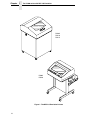
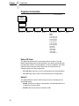
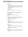
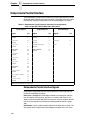
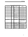
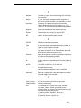
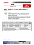
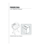
The P5000 series with DEC LG Emulation Printer Family
The DEC LG Emulation printers are a family of line matrix printers consisting
of 500, 1000, and 1500 line per minute (lpm) models packaged in various
configurations. All of the models offer software versatility and the latest
refinements in line matrix printing technology. The model numbers indicate
printing speed and physical configuration:
Table 1. The DEC LG Emulation
Model Number
10
Print Speed
Pedestal
Cabinet
á
P5005
500 lpm
P5205
500 lpm
P5010
1000 lpm
P5210
1000 lpm
á
P5215
1500 lpm
á
á
á
Printer Emulations
Most line matrix printers have specialized architectures, which enable the
printer to emulate, or behave like, another printer. These specialized
architectures are restricted. Your printer, however, introduces an open
architecture concept that is not available on any other line matrix printer.
Your printer is very easy to use. The message display and lights on the
control panel communicate with you directly and clearly. You can select every
function on your printer at the control panel, or you can send commands from
the host computer.
The printer has a feature called Flash memory, which allows you to download
programs from a diskette to your printer. Flash memory provides “instant”
booting of the printer. The absence of Read Only Memory (ROM) and the
flexibility of Flash memory makes program updates easy and eliminates the
need to swap parts to accommodate program changes.
The print mechanisms are housed in sound-insulation which make your
printer among the quietest impact printers in the world.
Printer Emulations
The following printer emulations (or protocols) are selectable at the control
panel:
•
•
Digital LG
•
•
IGP/PGL (optional)
LinePrinter Plus, which consists of:
IBM® Proprinter® III XL
Epson® FX-1050
Printronix P-Series
IGP/VGL (optional)
Each emulation provides a different set of configuration menus, control codes,
and character sets.
Host Computer Interfaces
The following host computer interface choices are available:
•
•
•
•
•
Centronics® parallel interface
IEEE® 1284 parallel interface
Dataproducts® parallel interface
RS-232 serial interface
RS-422 serial interface
11
Chapter
1
The P5000 series with DEC LG Emulation
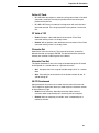
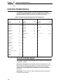
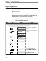
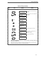
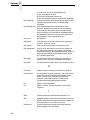
P5205
P5210
P5215
P5005
P5010
Figure 1. The DEC LG Emulation Printers
12
Graphics Enhancement Option
Graphics Enhancement Option
The IGP/PGL and IGP/VGL emulations allow you to create and store forms,
generate logos, bar codes, expanded characters, and create other graphics.
Alphanumeric and bar code data are added as the form is printed.
These emulations are available as factory-installed or field-installed options.
For more information, contact your authorized service representative.
Taking Care of Your Printer
Your printer will produce high print quality jobs if it is well taken care of.
Periodic cleaning, handling the printer properly, and using the correct paper
and ribbons, will ensure optimum performance. Chapter 6 explains how to
clean the printer, and printer supplies are listed in Appendix A.
Whenever it is necessary to service the printer, remember these important
maintenance concepts:
•
Use only the ribbons specified in Appendix A. Use of incorrect ribbons
can lead to ink migration problems, degraded print quality, and expensive
damage to the printer.
•
Incorrect closure of the forms thickness lever can lead to smearing,
degraded print quality, paper jams, and damage to the platen and shuttle
assembly. Never close the forms thickness lever too tightly.
•
Printing outside the boundaries of the paper will degrade print quality and
cause hammer bank damage. Never print outside of the paper width.
LinePrinter Plus Features
If you have enabled the LinePrinter Plus emulations, your printer will support
the following features:
Output Control
The printers have the following output control features:
•
Three modes for printing text:
1) Correspondence (NLQ)
2) Data Processing (DP)
3) Draft (high speed)
•
•
Selectable forms length and width
Character attribute specification:
1) Selectable pitch: normal, expanded, and compressed
2) Bold (double-strike) printing
3) Emphasized (shadow) printing
4) Automatic underlining and overscoring
5) Superscript and subscript printing
6) Double high and wide printing
•
Resident multinational character sets
13
Chapter
1
The P5000 series with DEC LG Emulation
Graphics and Vertical Formatting
Several graphics and vertical formatting features are available:
•
Four built-in graphics generators:
1) IBM Proprinter III XL bit-image graphics
2) Epson FX dot graphics mode
3) P-Series Plot
4) LG Sixel Graphics
•
Programmable electronic vertical formatting provides rapid vertical paper
movement to specified lines for printing repetitive and continuous forms.
You can choose from the following methods:
1) Vertical tabbing in Proprinter III XL and Epson FX emulation modes
2) Electronic Vertical Format Unit (EVFU) in P-Series emulation mode
3) Centronics Vertical Format Unit (CVFU) in P-Series
4) Dataproducts Vertical Format Unit (DVFU) in P-Series
Built-in Diagnostic Tools
The following diagnostic tools are provided with the printer:
•
•
•
Comprehensive diagnostic self-tests permanently stored in the printer
Configuration printout
Data stream hex code printout
Protocols and Emulations
A protocol is a set of rules governing the exchange of information between the
printer and its host computer. These rules consist of codes that manipulate
and print data and allow for machine-to-machine communication. A printer
and its host computer must use the same protocol. As used in this manual,
protocol and emulation mean the same thing.
Most impact printers use single ASCII character codes to print text, numbers,
and punctuation marks. Some characters, both singularly and in groups of two
or more, are defined as control codes. Control codes instruct the printer to
perform specific functions, such as underlining text, printing subscripts,
setting page margins, etc. The main difference between most printer
protocols is in the characters used to create control codes and the ways in
which these characters are formatted.
When the printer executes the character and control codes of a particular
printer protocol, it is “emulating” that printer. For example, if the printer uses
the Proprinter III XL protocol, it is emulating an IBM Proprinter III XL printer. If
the printer is using the Epson FX printer protocol, it is in Epson FX emulation
mode.
14
Line Matrix Printing
Line Matrix Printing
Your printer creates characters and graphics by a printing technique called
line matrix printing. Line matrix printing consists of printing patterns of ink dots
on paper, an entire line at a time.
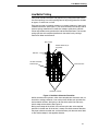
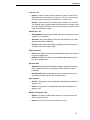
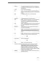
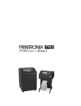
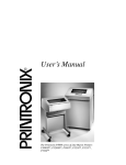
Each text character is stored in memory as a pattern of dots on a logical grid
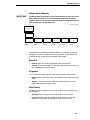
called the dot matrix. (See Figure 2.) The actual ink dots are made by a row of
hammer springs mounted on a shuttle that sweeps rapidly back and forth.
Printer logic divides every printable line into horizontal dot rows. The hammer
springs put dots at the required positions for the entire line by striking a
moving ink ribbon and the paper.
Dot Column
Matrix visible only to
the printer
Dot Row
Ink dots formed by
hammer tips
Character Row
Character Column
Figure 2. Dot Matrix Character Formation
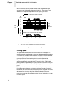
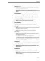
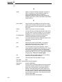
Unlike serial dot matrix printers, which form complete text characters one at a
time with a moving printhead, a line matrix printer divides each printable line
into horizontal dot rows, then prints a dot row of the entire line with every
lateral sweep of the shuttle. (See Figure 3.)
During each sweep of the shuttle, the hammers print dots at the required
positions in the dot row. At the end of a sweep, the shuttle reverses direction,
the paper advances one dot row, and the hammers print the next row of dots
as the shuttle sweeps in the opposite direction.
15
Chapter
1
The P5000 series with DEC LG Emulation
After a line of characters is printed, hammer action stops while the paper
advances to the first dot row of the next printable line. The number of rows
allowed for line separation depends on the line spacing you select.
Direction of Shuttle Movement
Dot
Row
Start
1
2
3
4
5
6
7
8*
9* *
10
Number of rows is determined by line spacing.
11
n
1
2
One
Text
Line
*
**
Paper
Feed
Direction
This row is used only for lowercase descenders.
This row is used for underlining and lowercase descenders.
Figure 3. Line Matrix Printing
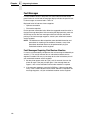
Printing Speed
The speed at which text prints is measured in lines per minute (lpm). This
speed is inversely proportional to the number of dot rows required to produce
a character line, regardless of the number of characters in the line. More dot
rows are required to print lowercase characters with descenders;
consequently, those character lines print at a fractionally lower rate.
The printer also prints dot-addressable graphic images. The speed at which
graphics are plotted is measured in inches per minute (ipm). Unidirectional
plotting produces slightly better print quality and takes about twice as long as
bidirectional plotting. You can select either plotting mode from the control
panel.
Printing and plotting rates also vary according to the print mode you select.
Print mode refers to the way you instruct the printer to create characters. If,
for example, you select near letter quality (NLQ) mode, the printer uses more
dot rows to form characters than if you choose high speed (HS) mode.
Character formation and print speed are faster in HS mode because the
printer prints fewer dot rows to form characters. Vertical dot density is a factor
in printing speed.
16
2
Setting Up the Printer
Before You Begin
Read this chapter carefully before installing and operating the DEC LG
Emulation printer.
The printer is easy to install, but for your safety, and to protect valuable
equipment, perform all the procedures in this chapter in the order presented.
Power Requirements
IMPORTANT
It is recommended that printer power be supplied from a separate AC
circuit protected at 10 amperes for 120 volts or 5 amperes for 230 volts
at 50 or 60 Hertz.
The printer must be connected to a power outlet that supplies 88 to 135 Volts
AC or 178 to 270 Volts AC at 47 to 63 Hz. The printer automatically senses
and adjusts itself to conform to the correct voltage range.
Primary circuit protection is provided by the power switch, which is also a
circuit breaker. Consult an electrician if printer operation affects local
electrical lines. See Appendix A for additional power specifications.
Select a Site
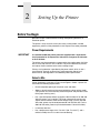
Printer dimensions are shown in Figure 4 and Figure 5. Select a printer site
that meets the following requirements:
•
•
Permits complete opening of the printer cover and doors.
•
Has a standard power outlet that supplies 100-120 Volts AC or 200-240
Volts AC power, at 47 to 63 Hz. The printer automatically senses and
adjusts itself to conform to the correct voltage range. (For the 100-120
Volt outlet, power may fluctuate between 88 and 135 Volts AC. For the
200-240 Volt outlet, power may fluctuate between 178 and 270 Volts.)
•
•
Is relatively dust-free.
Allows at least three feet of clearance behind the cabinet printer model.
(This permits air to circulate freely around the printer and provides access
to the paper stacking area.)
Has a temperature range of 10° C to 40° C (50° F to 104° F), and a
relative humidity from 15% to 90% non-condensing.
17
Chapter
2
Before You Begin
•
Is located within the maximum allowable cable length to the host
computer. This distance depends on the type of interface you plan to use,
as shown in Table 2:
Table 2. Interface Connections
Interface Type
Maximum Cable Length
Centronics Parallel
5 meters (15 feet)
IEEE 1284 Parallel
10 meters (32 feet)
Dataproducts Parallel
12 meters (40 feet)
Serial RS-232
15 meters (50 feet)
Serial RS-422
1220 meters (4000 feet)
Printer Cover
Cabinet Rear
Door
57.5 in.
(146.1 cm)
41.0 in.
(104.1 cm)
27.0 in.
(68.6 cm)
29.0 in.
(73.7 cm)
83.0 in.
(210.8 cm)
27.0 in.
(68.6 cm)
Figure 4. Cabinet Model Dimensions
18
27.0 in.
(68.6 cm)
Select a Site
25 in.
(63.5 cm.)
10.5 in.
(26.67 cm.)
48.0 in.
(122 cm.)
24.6 in.
(62.48 cm.)
30 in.
(76.2 cm.)
Figure 5. Pedestal Model Dimensions
19
Chapter
2
Before You Begin
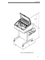
Printer Component Locations
Familiarize yourself with the names and locations of the printer components
shown in Figure 6 before continuing with the rest of the installation procedure.
Horizontal
Tractor Lock
Adjustment Knob
Paper Scale
Splined Shaft
Paper Support
Tractor
Hammer Bank Cover
and Ribbon Mask
Vertical Position
Knob
Ribbon Loading
Path Diagram
Forms Thickness
Lever
Figure 6. Component Locations
20
Remove the Cardboard Packing
Remove the Shipping Restraints (Cabinet Model)
Cardboard packing, protective foam, and tie wraps protect printer
mechanisms from damage during shipment. This section describes how to
remove these shipping restraints from the cabinet model before you operate
the printer.
Save the cardboard packing, foam blocks, and bubble wrap along with the
other packing materials, since you may need to reinstall them.
If it is necessary to move the printer, reinstall the shipping restraints. Reverse
the steps in this section.
CAUTION
To avoid shipping damage, reinstall the shipping restraints whenever
you move or ship the printer.
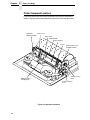
Remove the Cardboard Packing
Cardboard
Packing (2)
55blocks
August 8, 2000
Figure 7. Removing the Cardboard Packing
1. Raise the printer cover.
2. Remove the cardboard packing.
3. Remove the envelope that contains the sample configuration printout.
Store this in the pouch that is attached to the left interior side of the
cabinet.
21
Chapter
2
Remove the Shipping Restraints (Cabinet Model)
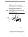
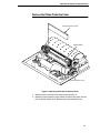
Remove the Hammer Bank Protective Foam and Foam
Strips
Hammer Bank
Protective Foam
Foam Strips (2)
Tractor Door
Tractor Lock
Figure 8. Removing the Hammer Bank Protective Foam and Foam Strips
1. Open the tractor doors. Push the tractor locks down. Slide the tractors
and paper supports outward as far as they will go. The forms thickness
lever should be in the fully open (raised) position.
2. Lift the hammer bank protective foam and remove it from between the
ribbon mask and the platen.
3. Remove the foam strips and the tape securing the foam strips.
22
Remove the Platen Protective Foam
Remove the Platen Protective Foam
Platen Protective Foam
Support Shaft
Forms Thickness Lever
Figure 9. Removing the Platen Protective Foam
1. Rotate the forms thickness lever downward to position “A”.
2. Rotate the platen protective foam toward the front of the printer and out
from under the support shaft. Remove the platen protective foam.
23
Chapter
2
Remove the Shipping Restraints (Cabinet Model)
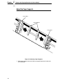
Adjust the Paper Supports
Tractor Door
Paper Supports
Tractor Door
Figure 10. Adjusting Paper Supports
1. Slide paper supports inward until they are approximately four inches from
the tractor door.
24
Release the Paper Chains
Release the Paper Chains
Tie Wrap
Paper Chains
Tie Wrap
Plastic Bags
Figure 11. Releasing the Paper Chains
1. Open the cabinet rear door.
2. Cut the tie wraps and release the paper chains from the bags at the top
rear of the printer frame. Remove the tie wraps and bags.
3. Make sure each chain hangs freely, with no kinks or knots.
25
Chapter
2
Remove the Shipping Restraints (Cabinet Model)
Remove the Tags
Tie Wrap
Passive Paper
Stacker
Tie Wrap
Fence
Tag
Tag
Figure 12. Remove Tag and Tie Wrap from Fence or Passive Paper
Stacker
1. Remove the tie wrap and large red tag attached to the passive paper
stacker.
2. Close the cabinet rear door.
3. Close the printer cover.
26
Attach the Control Panel Overlays
Attach the Control Panel Overlays
Figure 13. Attaching Control Panel Overlay
1. Choose the overlay labels in the appropriate language.
2. Open the printer cover, peel off the back of the overlay and apply to the
control panel.
Remove the Shipping Restraints (Pedestal Model)
Protective films and foam blocks protect printer mechanisms from damage
during shipment. This section describes how to remove these shipping
restraints from the pedestal model before you operate the printer.
Save the foam blocks, since you may need to reinstall them.
If it is necessary to move the printer, reinstall the shipping restraints. Reverse
the steps in this section.
CAUTION
To avoid shipping damage, reinstall the shipping restraints whenever
you move or ship the printer.
27
Chapter
2
Remove the Shipping Restraints (Pedestal Model)
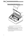
Remove the Hammer Bank Protective Foam
Hammer Bank
Protective Foam
Tractor Door
Tractor Lock
Figure 14. Removing the Hammer Bank Protective Foam
1. Raise the printer cover.
2. Open the tractor doors. Push the tractor locks down. Slide the tractors
and paper supports outward as far as they will go. The forms thickness
lever should be raised (in the fully open position).
3. Remove the envelope that contains the sample configuration printout.
4. Lift the hammer bank protective foam and remove it from between the
ribbon mask and the platen.
28
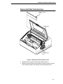
Remove the Platen Protective Foam
Remove the Platen Protective Foam
Platen Protective
Foam
Support Shaft
Forms Thickness
Lever
Figure 15. Removing Platen Protective Foam
1. Rotate the forms thickness lever downward to position “A”.
2. Rotate the platen protective foam toward the front of the printer and out
from under the support shaft. Remove the platen protective foam.
29
Chapter
2
Remove the Shipping Restraints (Pedestal Model)
Adjust the Paper Supports
Tractor Door
Paper Supports
Tractor Door
Figure 16. Adjusting Paper Supports
1. Slide paper supports inward until they are approximately four inches from
the tractor door.
2. Close the printer cover.
30
Remove Tag
Remove Tag
Tie Wrap
Tag
Figure 17. Removing Tag from Cage
Remove the tie wrap attached to the wireform paper path. It is marked with a
large, red tag.
31
Chapter
2
Remove the Shipping Restraints (Pedestal Model)
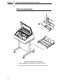
Attach the Output Basket
Figure 18. Attaching the Output Basket
1. Place the output basket in the holes in the back of the printer.
2. Screw the ground wire attached to the output basket to the printer.
32
Attach the Control Panel Overlays
Attach the Control Panel Overlays
Figure 19. Attaching Control Panel Overlays
1. Choose the overlay labels in the appropriate language.
2. Open the printer cover and insert overlay labels by sliding them behind
the control panel assembly in the appropriate place.
33
Chapter
2
Install Basic Components
Install Basic Components
The following section gives instructions on essential procedures which keep
your printer operational on a day-to-day basis.
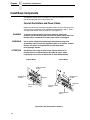
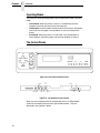
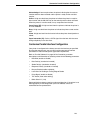
Connect the Interface and Power Cables
Before you connect the interface and power cables, verify the voltage source
at the printer site conforms to the requirements specified on page 17. Make
sure the printer power switch is set to OFF (see Figure 21).
WARNING
To prevent serious personal injury from electrical shock when
connecting or disconnecting the host interface (signal) cable, make sure
that the printer is powered off and the power cable is unplugged.
WARNUNG
Um ernstliche körperliche Verletzungen durch Stromschlag beim
Anschließen oder Trennen des Signalton-Kabels zu vermeiden, muß der
Drucker auf jeden Fall ausgeschaltet und der Netzstecker
herausgezogen werden.
ATTENTION
Afin d'éviter tout risque de blessure par électrocution lors du
branchement ou du débranchement du câble de signal, mettre
l'imprimante hors tension et débrancher le câble d'alimentation.
Pedestal Model
Cabinet Model
Centronics/IEEE
Parallel
Dataproducts
Parallel
Dataproducts
Parallel
Diagnostic
RS-232/RS-422
Serial
Diagnostic
Centronics/IEEE
Parallel
RS-232/RS-422
Serial
Figure 20. Cable Connection Locations
34
Connect the Interface and Power Cables
Cabinet Model
Pedestal Model
Host Interface
Connectors
I/O Cover
OFF/ON
Host Interface
Connectors
AC Power
Connector
Cable-Routing
Notch (2)
Power Switch
AC Power Cable
AC Power Connector
FGQHZLR
Figure 21. Interface and Power Locations
1. Make sure the printer power switch is set to OFF (see Figure 21).
Connect the (customer-supplied) interface cable from the host computer
to the appropriate printer interface connector (see Figure 20). Refer to
Chapter 5, “Interfaces,” for descriptions of the connectors and their pin
assignments.
a. Remove the cover from the interface connector you have selected.
b. Hold the interface cable below its connector, and gently attach the
cable connector to the printer interface connector.
2. Plug the power cord into the printer AC power connector, then into the AC
power outlet (see Figure 21).
35
Chapter
2
Install Basic Components
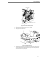
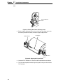
Install the Ribbon
Figure 22. Ribbon Path Diagram Location
1. Refer to the ribbon path diagram molded onto the shuttle cover.
55cabopn
MAy 1, 2001
Figure 23. Opening the Printer Cover
2. Verify that the printer is offline and that the printer cover is open.
36
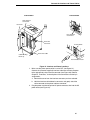
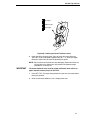
Install the Ribbon
Tractor Door
Forms Thickness Lever
Figure 24. Forms Thickness Lever
3. Raise the forms thickness lever as far as it will go.
4. Swing open the tractor doors.
Hub Latch
Figure 25. Right Hub Latch
5. Squeeze the right hub latch and place the full spool on the right hub. Be
sure the ribbon feeds off the outside of the spool. Press the spool down
until the hub latch snaps into place.
37
Chapter
2
Install Basic Components
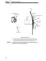
Paper
Hammer Bank Cover
Ribbon Mask
Ribbon Mask
Hammer Bank Cover
Platen
Ribbon
Front of
Printer
Hammer Tip
55rib2a
April 27, 2001
Ribbon Guide
Figure 26. Ribbon Path
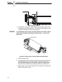
6. Thread the ribbon around the ribbon guide and along the ribbon path.
Refer to the ribbon path diagram on the shuttle cover. Be sure to thread
the ribbon between the hammer bank cover and the ribbon mask.
CAUTION
38
The ribbon must not be twisted. A twisted ribbon can lower print quality,
shorten ribbon life, and cause paper jams.
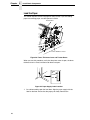
Install the Ribbon
Cabinet Model
55rib3
August 15, 2000
Pedestal Model
p55rib3
May 1, 2001
Figure 27. Left Ribbon Hub
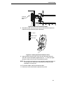
7. Place the empty spool on the left hub. Press the spool down until the hub
latch snaps into place. Turn the spool by hand to make sure the ribbon
tracks correctly in the ribbon path and ribbon guides.
39
Chapter
2
Install Basic Components
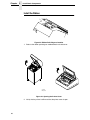
Load the Paper
This section explains how to load paper for the first time. If you are loading
paper over existing paper, see the Operator’s Guide.
Tractor Door
Forms Thickness Lever
Figure 28. Forms Thickness Lever and Tractor Doors
When you start this procedure, verify that the printer cover is open, the forms
thickness lever is raised, and the tractor doors are open.
EDGE
OF
PAPER
BOX
Figure 29. Paper Supply Label Location
1. On cabinet models, open the front door. Align the paper supply with the
label on the floor. Ensure that the paper pulls freely from the box.
40
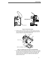
Load the Paper
Paper Slot is 8 inches
below printer base
Paper Slot
Figure 30. Paper Slot Location
2. Feed the paper up through the paper slot. Hold the paper in place with
one hand (to prevent it from slipping down through the paper slot) while
pulling it through from above with your other hand.
Tractor Door
Paper
Tractor Lock
Ribbon Path Diagram
Figure 31. Loading Paper Onto the Left Tractor Sprockets
3. Pull the paper above and behind the ribbon mask, which is a silver metal
strip with a clear plastic edge protector. Refer to the ribbon path diagram
on the shuttle cover. Load the paper on the left tractor sprockets and
close the tractor door. Normally, you should not need to adjust the
position of the left tractor.
41
Chapter
2
Install Basic Components
Paper Scale
Figure 32. Paper Scale
4. If adjustment is necessary, unlock the left tractor. Slide the tractor until it
is directly to the left of the number “1” on the paper scale and lock it. (You
can also use the paper scale to count columns.)
CAUTION
To avoid damage to the printer caused by printing on the platen, always
position the left tractor unit directly to the left of the “1” mark on the
paper scale.
Splined Shaft
Figure 33. Loading Paper Onto the Right Tractor Sprockets
5. Unlock the right tractor.
6. Load the paper onto the sprockets and close the tractor door. Make sure
the leading edge of the first sheet of paper is perfectly parallel to the
tractor splined shaft (paper is not crooked). If paper is crooked, reload it
onto the tractor sprockets until its edge is parallel to the splined shaft.
7. Slide the right tractor to remove paper slack or to adjust for various paper
widths. Then lock the tractor.
42
Load the Paper
Horizontal
Adjustment
Knob
Figure 34. Horizontal Adjustment Knob
8. After both tractors are secured, you may use the horizontal adjustment
knob to make fine horizontal paper adjustments.
A Thin Paper
B Medium Paper
C Thick Paper
Figure 35. Lowering the Forms Thickness Lever
9. Lower the forms thickness lever. Set it to match the paper thickness.
The A-B-C scale corresponds approximately to 1-, 3-, and 6-part paper
thickness. Adjust until you have the desired print quality.
NOTE: Do not set the forms thickness lever too tightly; excessive friction can
cause paper jams, ribbon jams with potential for ribbon damage,
smeared ink, or wavy print.
10. For cabinet models, close the cabinet front door.
11. Continue on to the next section to power on the printer.
43
Chapter
2
Install Basic Components
Power On the Printer
Following are instructions for powering on the printer after you have installed
the ribbon and loaded paper.
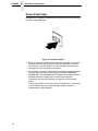
Figure 36. The Power Switch
1. When you start this procedure, verify that paper and ribbon are installed,
the forms thickness lever is lowered, and the tractor doors are closed.
This prevents a “LOAD PAPER” or “CLOSE PLATEN” error message
from displaying after the printer is powered on.
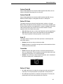
2. Set the power switch to the ON position (Figure 36). The printer initializes
and runs several self-tests. The messages “TESTING HARDWARE /
PLEASE WAIT” and “DIAGNOSTICS / PASSED” will each display briefly.
When the self-tests complete and the software has initialized
successfully, the message “ONLINE / LG” appears on the message
display.
If the status indicator flashes and a fault message displays, this indicates
a fault condition; refer to the fault messages section in Chapter 6,
“Routine Service and Diagnostics.”
44
Set the Top-of-Form
Set the Top-of-Form
Following are instructions for setting the top-of-form after you have powered
on the printer.
Paper Path
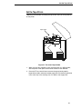
Figure 37. The Lower Paper Guide
1. When you start this procedure, verify that the printer is in offline mode,
with the printer cover open and the forms thickness lever lowered.
2. Press the FF key several times to ensure the paper feeds properly
beyond the tractors and over the lower paper path. Ensure the paper folds
in the same way in the stacking area as it does in the supply area.
45
Chapter
2
Install Basic Components
Forms Thickness
Lever
Figure 38. Raising the Forms Thickness Lever
3. Raise the forms thickness lever as far as it will go. This allows you to turn
the vertical position knob freely in order to align the top-of-form.
TOF Indicator
Perforation
Vertical Position
Knob
Figure 39. Aligning the Top-of-Form
4. Locate the TOF indicator. It is the small tab located on the tractor doors.
5. Turn the vertical position knob to align the top of the first print line with the
TOF indicator.
46
Set the Top-of-Form
A Thin Paper
B Medium Paper
C Thick Paper
Figure 40. Lowering the Forms Thickness Lever
6. Lower the forms thickness lever. Set it to match the paper thickness.
The A-B-C scale corresponds approximately to 1-, 3-, and 6-part paper
thickness. Adjust until you have the desired print quality.
NOTE: Do not set the forms thickness lever too tightly; excessive friction can
cause paper jams, ribbon jams with potential for ribbon damage,
smeared ink, or wavy print.
IMPORTANT
The forms thickness lever must be closed; otherwise, there will be no
paper movement when you press SET TOF.
7. Press SET TOF. The top-of-form position that you have set moves down
to the print position.
8. Go on to the next procedure to run a simple printer test.
47
Chapter
2
Install Basic Components
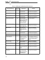
Test the Printer
Table 3. Printer Test Procedure
Step
1.
2.
3.
Key
Result
Notes
Make sure that the printer top cover is open and the forms thickness lever is lowered.
ONLINE
+
OFFLINE
CONFIG. CONTROL
The printer must be off line for
testing.
ENTER SWITCH
UNLOCKED
Allows you to make configuration
changes.
OFFLINE
CONFIG. CONTROL
4.
UNTIL
5.
DIAGNOSTICS
Printer Tests
6.
Printer Tests
Shift Recycle*
7.
R/S
8.
R/S
9.
10.
OFFLINE
DIAGNOSTICS
+
CLEAR
Printer Tests
Shift Recycle*
Printer Tests
Shift Recycle*
The printer outputs a sliding
alphabet pattern.
Stops test.
ENTER SWITCH
LOCKED
Locks the configuration
parameters.
OFFLINE
CONFIG. CONTROL
Moves the printer out of the
menus to offline.
11.
Examine the print quality. The characters should be fully formed and of uniform
density. If the test does not run or characters appear malformed, contact your
authorized customer service engineer.
12.
If the print quality is good, close the printer cover; press ONLINE to enable printing. To
select an emulation and configure the printer with the control panel, go to Chapter 3.
48
3
Configuring the Printer
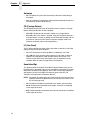
Overview
IMPORTANT
Configuration directly affects printer operation. Do not change the
configuration of your printer until you are thoroughly familiar with the
procedures in this chapter.
In order to print data, the printer must respond correctly to signals and
commands received from the host computer. Configuration is the process of
matching the printer operating characteristics to those of the host computer
and to specific tasks, such as printing labels, or printing on different sizes of
paper. The characteristics that define the printer’s response to signals and
commands received from the host computer are called configuration
parameters.
You can configure the printer using the configuration menus and the control
panel, or by sending control codes in the data stream from a host computer
attached to the printer.
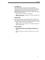
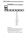
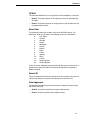
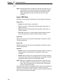
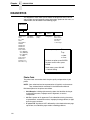
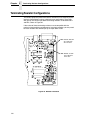
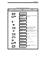
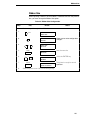
This chapter provides a tutorial introduction. Figure 41 shows an overview of
the configuration menus.
Following the menu is background information on topics such as changing
and saving parameters, custom configurations, and operating modes. Several
step-by-step procedures are also provided that show how to change
configuration parameters and how to save, print, and load configurations from
printer memory. For details on the entire set of configuration menu options,
see Chapter 4.
The host control codes for each emulation are described in their
corresponding Programmer’s Reference Manual. See “Related Documents”
on page 9 for more information.
49
Chapter
3
Overview
OFFLINE
CONFIG.
CONTROL
Load Config.
Save Config.
Print Config.
Delete Config.
Power-Up Config.
Protect Configs.
PRINTER
CONTROL
Unidirectional
PMD Fault
Slow Paper Slew
Power Saver Time
ACTIVE
EMULATION1
EMULATION
LG*
LinePrinter+
IGP/PGL & LP+
IGP/VGL & LP+
LG*
LinePrinter+
IGP/PGL & LP+
IGP/VGL & LP+
DIAGNOSTICS
RIBBON
MINDER
Printer Tests
Test Width
Paper Out Dots
System Memory
Print Statistics
New Ribbon
Ribbon Action
Ribbon Size
Ribbon Adjust
Fault Action
HOST
INTERFACE
MAINT/MISC
Hex Dump Mode
Power-Up State
Display Language
Serial*
Parallel
Centronics
Dataproducts
Bidirectional
To view options, press:
1
Choices available are limited to the emulations
configured with the printer.
⇓ Down
⇑ Up
⇒ Next
⇐ Prev
To select an option, press ENTER.
To return to main menu, press
CLEAR.
To exit menu, press ONLINE.
* = Default Setting
Figure 41. Configuration Menu Overview
50
Changing and Saving Parameter Settings
Changing and Saving Parameter Settings
You can change a parameter setting, such as line spacing or forms length, by
pressing keys on the control panel or by sending emulation control codes in
the host data stream. Refer to the appropriate Programmer’s Reference
Manual for information about control codes.
When you change a parameter, it is active as long as the printer is on or until
changed. This is true whether you used the control panel or sent a control
code from the host.
If you use the control panel, you can save the parameters as a customized
configuration. A configuration consists of a group of parameters. A saved
configuration will not be lost if you turn off the printer although the printer will
not power up in this configuration unless saved as the power-up configuration.
You can change a parameter with a control code, but to save the parameter
setting you must use the control panel.
Control codes override control panel parameters. For example, if you set the
line spacing to 6 lpi with the control panel, and application software later
changed this to 8 lpi with a control code, the control code setting overrides the
control panel setting.
The 8 lpi parameter is effective as long as the printer is on or until changed. If
you turn off the printer, the 8 lpi parameter will be erased. To save the
parameter, you must use the control panel and save it as a configuration.
Default and Custom Configurations
A configuration consists of a group of parameter settings, such as line
spacing, forms length, etc. Your printer provides a fixed default configuration
and also allows you to define several custom configurations for use with
particular print jobs.
•
The factory default configuration (configuration 0) can be loaded, but it
cannot be altered. See page 53 for a list of all the factory default
parameter values.
•
Eight configurations can be modified for unique print job requirements.
The “Save Config.” option allows you to save eight groups of parameter
settings in non-volatile memory as custom configurations numbered from
1 through 8. See page 57 for an explanation of how to save a set of
parameter values as a custom configuration using the “Save Config.”
menu option.
51
Chapter
3
Overview
Operating Modes
The printer has three operating modes: online mode, offline mode, and fault
mode.
•
Online Mode. When the printer is online, it is controlled by the host
computer and prints data sent by the host computer.
•
Offline Mode. In offline mode, communication with the host is interrupted
so that you can load paper, change ribbons, or test and configure the
printer.
•
Fault Mode. When the printer is in fault mode, it has encountered an
error condition, and printing stops until the error condition is cleared.
The Control Panels
CLEAR
UP
R/S
PREV
NEXT
SET TOF
DOWN
ON LINE
FF
LF
ENTER
Figure 42. The Cabinet Control Panel
SET
TOF
UP DOWN
PREV NEXT
CLEAR
R/S
ON LINE
ENTER
LF
FF
VIEW
Figure 43. The Pedestal Control Panel
When you are navigating within the configuration menus (in offline mode),
several of the control panel keys have specialized functions. They are
described in the Operator’s Guide.
52
VIEW
Unlocking and Locking the ENTER Key
Unlocking and Locking the ENTER Key
The ENTER key is locked by default, to prevent you from accidentally
changing the printer configuration. You should generally unlock the ENTER
key directly before you begin configuration using the menus; once the
changes are made, relock the ENTER key to secure your new settings.
To unlock the ENTER key, place the printer in the offline mode and press UP
and DOWN simultaneously. The following message will display briefly:
ENTER SWITCH
UNLOCKED
To lock the ENTER key, place the printer in offline mode and press UP and
DOWN simultaneously. The following message will display briefly:
ENTER SWITCH
LOCKED
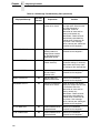
Factory Default Configuration Values
The factory default values are permanently stored in memory as a
configuration. They cannot be modified or erased.
EMULATION LG
LG
Font
StyleDP 10 6
Character SetUS ASCII
Vert. Forms
Bot Frm66/6
Top Mrg0/6
Horiz. Forms
Left Mrg00.0
Right Mrg13.6
AutowrapNo
CR=CR
LF=LF
Unsolicited RptNo
Print Mode OptEnable
Plot Mode OptEnable
I-2/5 Guard BarsEnable
LinePrinter+
Printer Protocol
Proprinter
Define CR codeCR=CR
Auto LFEnable
Define LF codeLF = LF
FF Valid at TOFEnable
Character SetCode Page 437
Alt Char SetSet 1
20 CPI CondensedEnable
CPI/LPI Select
Select CPI10.0 CPI
Select LPI6.0 LPI
Font Attributes
TypefaceData Processing
Prop. SpacingDisable
Bold PrintDisable
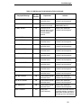
53
Chapter
3
Overview
Italic PrintDisable
Slashed ZeroDisable
Page Format
Margins
Left Margin0 columns
Right Margin0 columns
Bottom Margin0 lines
Perforation SkipDisable
Form Length
Abs. Length IN11.0 inches
Abs. Length MM279.4 mm
Function of lines66 lines
Form Width
Abs. Width IN13.6 inches
Abs. Width MM345.4 mm
Function of CPI136 characters
MAINT / MISC
Hex Dump ModeDisable
Power-up StateOnline
Display LanguageEnglish
HOST INTERFACE
Serial
Interface TypeRS-232
Data ProtocolXON/XOFF
Baud Rate9600 Baud
Word Length8
Stop Bits1
ParityNone
Data Term ReadyTrue
Request to SendTrue
Buffer Size8 Kbyte
PRINTER CONTROL
UnidirectionalDisable
PMD FaultEnable
Slow Paper SlewDisable
Power Saver Time15 min.
DIAGNOSTICS
Printer TestsShift Recycle
Test WidthFull Width
Paper Out Dots40 dots
RIBBONMINDER
Ribbon ActionDisable
Ribbon Size100 Yards1
Ribbon Adjust0
Fault ActionNew Ribbon
1
54
Default is 60 yards for pedestal models
Example
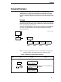
Changing Parameters
A configuration consists of several parameters. The default factory
configuration has a starting set of parameters. Your print jobs may require
different parameter settings from the default that is provided. This section
provides an example procedure for changing and saving individual parameter
values.
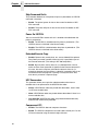
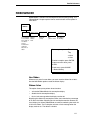
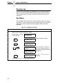
Example
The following procedure shows how to change and save the settings for the
Unidirectional option. Use these basic guidelines to navigate the configuration
menus and change other parameters.
If you think the configuration for your printer has already been changed from
the default, you should load the default configuration before starting this
procedure (page 63).
* = Factory Default
OFFLINE
CONFIG.
CONTROL
...
PRINTER
CONTROL
PMD Fault
Unidirectional
Disable*
Enable
Enable*
Disable
Slow Paper
Slew
Disable*
Enable
Power Saver
Time
15* - 60 Min.
Instant
NOTE: Once you change active emulations, any changes to the previously
selected emulation will be gone unless they have been saved.
Table 4. Parameter Change Example Procedure
Step
1.
2.
3.
Key
Result
Notes
Make sure the printer is on. Raise the printer cover.
ONLINE
+
OFFLINE
CONFIG. CONTROL
ENTER SWITCH
UNLOCKED
Allows you to make configuration
changes.
OFFLINE
CONFIG. CONTROL
55
Chapter
3
Changing Parameters
Table 4. Parameter Change Example Procedure (continued)
Step
Key
4.
UNTIL
5.
Notes
OFFLINE
PRINTER CONTROL
PRINTER CONTROL
Unidirectional
6.
Unidirectional
Disable*
7.
OR
8.
Result
ENTER
Unidirectional
Enable
Unidirectional
Enable*
Cycle through the choices.
An asterisk (*) indicates this
choice is active.
TO SAVE YOUR CHANGES AS A CONFIGURATION THAT IS STORED IN MEMORY:
1.
UNTIL
2.
3.
UNTIL
OFFLINE
PRINTER CONTROL
OFFLINE
CONFIG. CONTROL
Go to the CONFIG. CONTROL submenu Save Config. option, as described on page
58, step 4.
TO USE THE CURRENT CONFIGURATION WITHOUT SAVING:
1.
2.
3.
56
+
ONLINE
ENTER SWITCH
LOCKED
ONLINE
On cabinet models, close the printer cover. The printer is ready for operation. All
parameters are effective as long as the printer is on. When you turn off the printer, the
parameters will be erased from memory.
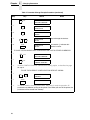
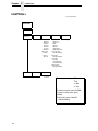
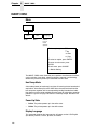
Saving Your New Configuration
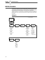
Saving Your New Configuration
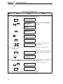
* = Factory Default
CONFIG.
CONTROL
Load Config.
Save Config.
Print Config.
Delete Config.
Power-Up
Config.
Protect
Configs.
1
2
3
4
5
6
7
8
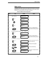
After changing all of the necessary parameters, it is recommended you save
them as a configuration that can be stored and loaded later for future use. If
you do not save your configuration before you power off the printer, all of your
parameter changes will be erased. The Save Config. option allows you to
save up to eight configurations to meet different print job requirements.
Configurations 1 through 8 are empty until you save values to them using the
Save Config. option. For example:
Config 1: Selects DP typeface, 10 cpi, 6 lpi
Config 2: Selects NLQ typeface, 12 cpi, 8 lpi
Once you have saved a configuration using this option, it will not be lost if you
power off the printer. You can load a configuration for a specific print job
(page 63). You can also modify and resave it. You may want to print your
configurations and store them in a safe place, such as inside the printer
cabinet.
NOTE: The Protect Configs. parameter must be set to disable before you
may save a configuration. Once you save a configuration, the Protect
Configs. parameter automatically returns to enable. Once you change
active emulations, any changes to the previously selected emulation
will be gone unless they have been saved.
57
Chapter
3
Changing Parameters
Table 5. Saving Configurations
Step
1.
2.
3.
Key
Result
Notes
If you are already in the configuration menu, go to step 5.
ONLINE
OFFLINE
CONFIG. CONTROL
ENTER SWITCH
UNLOCKED
+
Allows you to make configuration
changes.
OFFLINE
CONFIG. CONTROL
4.
CONFIG. CONTROL
Load Config.
5.
UNTIL
6.
CONFIG. CONTROL
Save Config.
Save Config.
1*
7.
OR
Save Config.
2
Press until the desired number
(1-8) displays.
NOTE: Do not turn off the printer while save is in progress because you might lose your
configuration.
8.
ENTER
9.
UNTIL
Save Config.
2*
The configuration is now saved in
memory. (In this case, config. 2.)
CONFIG. CONTROL
Save Config.
NOTE: It is recommended you print the configuration. Go to page 62, step 5. If you decide not
to print the configuration, then continue with the following steps.
10.
11.
12.
58
+
ONLINE
ENTER SWITCH
LOCKED
Locks the ENTER key.
ONLINE
Close the printer cover. The printer is ready for operation.
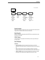
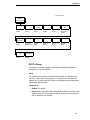
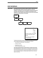
Deleting Your Configuration
Deleting Your Configuration
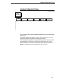
* = Factory Default
CONFIG.
CONTROL
Load Config.
Save Config.
Print Config.
Delete Config.
Power-Up
Config.
Protect
Configs.
1*
2
3
4
5
6
7
8
If you wish to delete a configuration from memory, select the appropriate
configuration number from the menu and press ENTER.
The Protect Configs. parameter must be set to disable before you may delete
a configuration. Once you delete a configuration the Protect Configs.
parameter automatically returns to enable.
59
Chapter
3
Changing Parameters
Table 6. Deleting Configurations
Step
1.
2.
3.
Key
Result
Notes
Make sure the printer is on. Raise the printer cover.
ONLINE
OFFLINE
CONFIG. CONTROL
ENTER SWITCH
UNLOCKED
+
Allows you to make configuration
changes.
OFFLINE
CONFIG. CONTROL
4.
CONFIG. CONTROL
Load Config.
5.
UNTIL
6.
Delete Config.
1*
7.
OR
8.
CONFIG. CONTROL
Delete Config.
ENTER
Delete Config.
3
Deleting Configuration
Press until the desired number
(1-8) displays.
The printer has deleted the
selected configuration.
Delete Config.
3*
9.
10.
11.
60
+
ONLINE
ENTER SWITCH
LOCKED
Locks the ENTER key.
ONLINE
Close the printer cover. The printer is ready for operation.
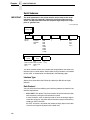
Protecting Your Configurations
Protecting Your Configurations
* = Factory Default
CONFIG.
CONTROL
Load Config.
Save Config.
Print Config.
Delete Config.
Power-Up
Config.
Protect
Configs.
Enable*
Disable
In order to save or delete a configuration you must set the Protect Configs.
option to disable. The Protect Configs. selection will automatically return to
enable once a configuration is saved or deleted.
Printing the Current Configuration
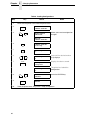
* = Factory Default
CONFIG.
CONTROL
Load Config.
Save Config.
Print Config.
Delete Config.
Power-Up
Config.
Protect
Configs.
Current*
Factory
Power-Up
All
1
2
3
4
5
6
7
8
The configuration printout lists the stored parameters. You can print any or all
of the configurations shown above. Configurations 1-8 are customized
configurations.
To print a configuration, follow the procedure in Table 7.
61
Chapter
3
Changing Parameters
Table 7. Printing Configurations
Step
1.
2.
3.
Key
Result
Notes
Make sure the printer is on. Raise the printer cover.
ONLINE
OFFLINE
CONFIG. CONTROL
ENTER SWITCH
UNLOCKED
+
Allows you to make configuration
changes.
OFFLINE
CONFIG. CONTROL
4.
CONFIG. CONTROL
Load Config.
5.
UNTIL
6.
Print Config.
Current*
7.
OR
8.
9.
10.
11.
12.
62
CONFIG. CONTROL
Print Config.
ENTER
Print Config.
All
Press until the desired option
displays.
OFFLINE
CONFIG. CONTROL
The configuration listing begins
printing.
Carefully tear off the configuration printout.
+
ONLINE
ENTER SWITCH
LOCKED
Locks the ENTER key.
ONLINE
Close the printer cover. Store the printout in a safe place. The printer is ready for
operation.
Loading Configuration Values
Loading Configuration Values
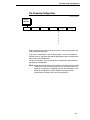
* = Factory Default
CONFIG.
CONTROL
Load Config.
Save Config.
Print Config.
Delete Config.
Power-Up
Config.
Protect
Configs.
0*
1
2
3
4
5
6
7
8
You can load any of the eight customized configurations or the factory default
configuration.
The loaded configuration remains active as long as the printer is on. If you
power off the printer, the power-up configuration will load.
“The Power-Up Configuration” on page 65 explains how to select the powerup configuration. If you do not set a power-up configuration, the factory
default configuration will load if you power the printer off and then back on.
NOTE: A configuration must be saved before you can load it.
63
Chapter
3
Changing Parameters
Table 8. Loading Configurations
Step
1.
2.
3.
Key
Result
Notes
Make sure the printer is on. Raise the printer cover.
ONLINE
+
OFFLINE
CONFIG. CONTROL
ENTER SWITCH
UNLOCKED
Allows you to make configuration
changes.
OFFLINE
CONFIG. CONTROL
4.
CONFIG. CONTROL
Load Config.
5.
Load Config.
1*
6.
OR
7.
ENTER
Load Config.
4
Loading Saved
Configuration
Load Config.
4*
8.
9.
10.
64
+
ONLINE
ENTER SWITCH
LOCKED
Press until the desired number
(1-8) displays.
Displays for about a second.
The printer has loaded the
configuration.
Locks the ENTER key.
ONLINE
Close the printer cover. The printer is ready for operation.
The Power-Up Configuration
The Power-Up Configuration
* = Factory Default
CONFIG.
CONTROL
Load Config.
Save Config.
Print Config.
Delete Config.
Power-Up
Config.
Protect
Configs.
0*
1
2
3
4
5
6
7
8
When you power on the printer for the first time, it loads configuration 0, the
factory default configuration.
If you save a configuration, such as configuration 1, and turn the power off
and then back on, the printer will load the designated power-up configuration,
not the last saved configuration.
For your convenience, you can specify which configuration (0-8) should be
the power-up configuration.
NOTE: When you change from the LG emulation to LinePrinter Plus (or from
LinePrinter Plus to the LG emulation) as your active emulation, the
power-up configuration is loaded for the new active emulation. (If no
power-up configuration has been defined, the factory default
configuration is loaded as the new active emulation.)
65
Chapter
3
Changing Parameters
Table 9. Setting The Power-Up Configuration
Step
1.
2.
3.
Key
Result
Notes
Make sure the printer is on. Raise the printer cover.
ONLINE
OFFLINE
CONFIG. CONTROL
ENTER SWITCH
UNLOCKED
+
Allows you to make configuration
changes.
OFFLINE
CONFIG. CONTROL
4.
CONFIG. CONTROL
Load Config.
5.
UNTIL
6.
Power-Up Config.
0*
7.
OR
8.
9.
10.
11.
66
CONFIG. CONTROL
Power-Up Config.
ENTER
+
ONLINE
Power-Up Config.
6
Press until the desired number
(1-8) displays.
Power-Up Config.
6*
The printer has selected the
desired configuration.
ENTER SWITCH
LOCKED
Locks the ENTER key.
ONLINE
Close the printer cover. The printer is ready for operation.
4
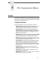
The Configuration Menus
Overview
Once you have familiarized yourself with the configuration process using the
tutorial information in Chapter 3, you are ready to complete your configuration
of the printer. This chapter provides descriptions for each parameter. Figure
44 shows the main configuration menu.
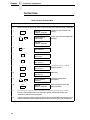
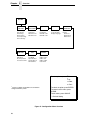
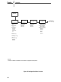
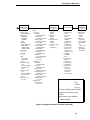
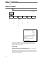
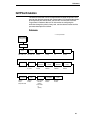
Configuration Main Menu
Brief descriptions follow for the first-level configuration menu options:
•
CONFIG. CONTROL. These options allow you to save, print, load, and
delete entire sets of configuration parameters. These options are
described briefly in this chapter and covered in detail in Chapter 3.
•
ACTIVE EMULATION. This menu allows you to select either the LG
(Digital) emulation or the LinePrinter Plus emulation as the current
operating emulation for your printer. If the IGP/PGL or IGP/VGL optional
upgrade is installed, then IGP/PGL & LP+ or IGP/VGL & LP+ can be
selected as the active emulation.
•
EMULATION. This menu allows you to configure the options available for
the currently active emulation. For example, if LG is the active emulation,
then the LG emulation options can be configured using this menu.
•
MAINT / MISC. These options provide miscellaneous functions, such as
printing a hex dump, selecting a display language, and choosing whether
the printer will power up in the offline or online state.
•
HOST INTERFACE. These options allow you to select either the Serial
RS-232, Serial RS-422, Centronics parallel, Dataproducts parallel, or
IEEE 1284 parallel interface for the printer (which must match the
interface cabling you installed while setting up your printer, described in
Chapter 2). This menu also allows you to configure several parameters
for each interface.
•
PRINTER CONTROL. These options allow you to select several
operating parameters for the printer, such as the speed at which paper
will advance when slewing.
•
DIAGNOSTICS. These options include the diagnostic tests, system
memory, and statistics of the printer.
•
RIBBONMINDER. The options in this submenu allow you to enable the
RibbonMinder™ feature and set its parameters.
67
Chapter
4
Overview
OFFLINE
CONFIG.
CONTROL
(see page 70)
Load Config.
0* - 8
Save Config.
1* - 8
Print Config.
Current*
Factory
Power-Up
All
1-8
Delete Config.
1* - 8
Power-Up Config.
0* - 8
Protect Configs.
Enable*
Disable
ACTIVE IGP
EMULATION1
(see page 72)
LG*
LinePrinter+
IGP/PGL1
IGP/VGL1
EMULATION
(see page 73)
LG*
LinePrinter+
IGP/PGL1
IGP/VGL1
MAINT/MISC
(see page 102)
Hex Dump Mode
Disable*/Enable
Power-Up State
Online*/Offline
Display Language
English*
German
French
Italian
Spanish
NOTES:
1
Choices available are limited to the emulations configured with the printer.
Figure 44. Configuration Menu Overview
68
Continued on
the next page
Configuration Main Menu
HOST
INTERFACE
(see page 103)
Serial*
Interface Type
RS-232*/RS-422
Data Protocol
XON/XOFF*
ETX/ACK
ACK/NAK
DTR
Baud Rate
600, 1200, 2400
4800, 9600*,
19200, 38400
57600, 115200
Word Length
8* or 7
Stop Bits
1* or 2
Parity
None*, Odd
Even, Mark
Sense
Data Term Ready
True*
On-Line and BNF
Off-Line or BF
False
Request to Send
True*
On-Line and BNF
Off-Line or BF
False
Buffer Size in K
8* (1-16)
PRINTER
CONTROL
(see page 112)
Parallel
Centronics
Data Bit 8
Enable*/Disable
Data Polarity
Standard*/Inverted
Strobe Polarity
Standard*/Inverted
Resp. Polarity
Standard*/Inverted
Busy On Strobe
Enable*/Disable
Latch Data On
Leading*/Trailing
Prime Signal
Enable*/Disable
TOF Action
Reset*/Do Nothing
Buffer Size in K
8* (1-16)
Dataproducts
Data Bit 8
Enable*/Disable
PI Ignored
Enable*/Disable
Data Polarity
Standard*/Inverted
Data Request Pol.
Standard*/Inverted
Strobe Polarity
Standard*/Inverted
Buffer Size in K
8* (1-16)
Bidirectional
Buffer Size in K
8* (1-16)
Unidirectional
Disable*
Enable
PMD Fault
Enable*
Disable
Slow Paper Slew
Disable*
Enable
Power Saver Time
15 min.*
(15-60 min.)
DIAGNOSTICS
(see page 114)
RIBBON
MINDER
(see page 117)
Printer Tests
Shift Recycle*
All E’s
E’s + TOF
All H’s
All Underlines
All Black
Shuttle Slow
Shuttle Fast
Shuttle Only
Phase Printer
Paperout Adj.
Burnin Test
Print Error Log
Clear Error Log
Test Width
Full Width*
80 col.
Paper Out Dots
40 dots*
(4-76 dots)
System Memory
x Megabytes
Print Statistics
On xx Hrs.
Print xx Hrs.
Print Strokes
Print Lines
11 Inch Pages
New Ribbon
Ribbon Action
Disable*
Display
Fault
Ribbon Size
100 yards*
(1-255 yards)
Ribbon Adjust
0*
(-99% - 99%)
Fault Action
New Ribbon*
Do Nothing
To view options, press:
⇓ Down
⇑ Up
⇒ Next
⇐ Prev
To select an option, press ENTER.
To return to main menu, press
CLEAR.
To exit menu, press ONLINE.
* = Default Setting
Figure 44. Configuration Menu Overview (continued)
69
Chapter
4
CONFIG. CONTROL
CONFIG. CONTROL
Menu
* = Factory Default
CONFIG.
CONTROL
Load Config.
0*
1
2
3
4
5
6
7
8
Save Config.
1*
2
3
4
5
6
7
8
Print Config.
Current*
Factory
Power-Up
All
1
2
3
4
5
6
7
8
Delete Config.
1*
2
3
4
5
6
7
8
Power-Up
Config.
0*
1
2
3
4
5
6
7
8
To view options, press:
Protect
Configs.
Enable*
Disable
⇓ Down
⇑ Up
⇒ Next
⇐ Prev
To select an option, press ENTER.
To return to main menu, press
CLEAR.
To exit menu, press ONLINE.
* = Default Setting
The CONFIG. CONTROL menu manages configurations, which are
groupings of parameter values that can be stored in printer memory. Brief
descriptions follow for each option.
Load Config.
The printer can store any of nine configurations in memory. This parameter
allows you to select and load a specific configuration.
Configuration 0 is the factory default; its parameters cannot be changed. It is
always available for loading. See page 63 for a fuller description and sample
procedure for using this option.
70
Menu
Save Config.
This option allows you to save up to eight unique configurations to meet
different print job requirements. This eliminates the need to change the
parameter settings for each new job.
The configurations are stored in memory, and will not be lost if you turn off the
printer. Configuration 0 is a factory-preset configuration, which cannot be
changed or saved. See page 55 for a fuller description and sample procedure.
The Protect Configs. parameter must be set to disable before you may save a
configuration. Once you save a configuration, the Protect Configs. parameter
automatically returns to enable.
Print Config.
This option is used to output a listing of various stored printer configurations. It
is recommended you store the configuration printouts in a safe place for quick
referral. See page 61 for a fuller description and sample procedure.
Delete Config.
You can delete one or all of your eight customized configurations. The Protect
Configs. parameter must be set to disable before you may delete a
configuration. Once you delete a configuration the Protect Configs. parameter
automatically returns to enable. Configuration 0 is a factory-preset
configuration and cannot be changed or deleted.
Power-Up Config.
You can specify which of the nine configurations (0-8) will be the power-up
configuration. The factory default for power-up is configuration 0. See page 65
for a fuller description and sample procedure.
Protect Configs.
The default for this function is always enable. To save or delete a
configuration, you must first set this option to disable. After saving or deleting
a configuration, this option automatically returns to enable.
71
Chapter
4
ACTIVE EMULATION
ACTIVE EMULATION
ACTIVE
EMULATION
LG*
LinePrinter+
IGP/PGL
& LP+1
IGP/VGL
& LP+1
To view options, press:
⇓ Down
⇑ Up
⇒ Next
⇐ Prev
To select an option, press ENTER.
To return to main menu, press
CLEAR.
To exit menu, press ONLINE.
1
= if installed
* = Default Setting
The ACTIVE EMULATION menu allows you to select the emulation to be
used with your DEC LG Emulation printer. Digital LG is the default active
emulation. You can also select LinePrinter Plus as the active emulation. The
Proprinter XL, Epson FX, and P-Series emulations are all part of LinePrinter
Plus. You may configure options for the active emulation via the EMULATION
menu, described on page 73.
If the IGP/PGL or IGP/VGL graphics upgrade option is installed, the display
looks somewhat different, as follows:
•
If IGP/PGL is installed, only the following option displays:
“IGP/PGL & LP+”
•
If IGP/VGL is installed, only the following option displays:
“IGP/VGL & LP+”
NOTE: When you change from LG to LinePrinter Plus (or from LinePrinter
Plus to LG) as your active emulation, the power-up configuration is
loaded for the new active emulation. (If no power-up configuration
has been defined, the factory default configuration is loaded.)
72
Menu
EMULATION
EMULATION
LG*
LinePrinter+
IGP/PGL1
IGP/VGL1
page 74
page 78
page 89
page 94
To view options, press:
⇓ Down
⇑ Up
⇒ Next
⇐ Prev
To select an option, press ENTER.
To return to main menu, press
CLEAR.
To exit menu, press ONLINE.
1Optional
Emulation
* = Default Setting
The EMULATION menu is the gateway to configuring the emulations
available with the DEC LG Emulation.
NOTE: Only the emulation currently selected from the ACTIVE EMULATION
menu can be selected and configured on the EMULATION menu.
•
LG. If LG is the active emulation, then the options for this emulation can
be selected and configured. The LG emulation is provided for
compatibility with the Digital LG printer control language.
•
LinePrinter+. If LinePrinter+ is the active emulation, the options for the
following emulations can be selected and configured:
• Proprinter XL. This LinePrinter+ emulation is provided for
compatibility with the IBM Proprinter III XL printer control language.
•
Epson FX. This LinePrinter+ emulation is provided for compatibility
with the Epson FX-1050 printer control language.
•
P-Series. This LinePrinter+ emulation is provided for compatibility
with the Printronix P-Series printer control language.
•
IGP/PGL & LP+. If you have installed the IGP/PGL optional upgrade,
then the options for this emulation can be selected and configured. The
IGP/PGL emulation is fully described in the DEC LG Emulation IGP/PGL
Programmer’s Reference Manual.
•
IGP/VGL & LP+. If you have installed the IGP/VGL optional upgrade,
then the options for this emulation can be selected and configured. The
IGP/VGL emulation is fully described in the DEC LG Emulation IGP/VGL
Programmer’s Reference Manual.
73
Chapter
4
Digital LG
Digital LG
Submenu
* = Factory Default
EMULATION
LG
Font
Vert. Forms
Bot. Frm 66/6*
(0-198)
Top Mrg 0/6*
(0-198)
Style
DP 10 6*
DP 10 8
DP 12 6
DP 12 8
DP 15 6
DP 15 8
DP 15 10
HS 10 6
CORESPON 5 6
CORESPON 5 8
CORESPON 6 6
CORESPON 6 8
CORESPON 10 6
CORESPON 10 8
CORESPON 12 6
CORESPON 12 8
CORESPON 15 6
CORESPON 15 8
CORESPON 15 10
OCR A
OCR B
COMPRESS 6 6
COMPRESS 6 8
COMPRESS 8 6
COMPRESS 8 8
COMPRESS 13 6
COMPRESS 13 8
COMPRESS 13 10
COMPRESS 16 6
COMPRESS 16 8
COMPRESS 16 10
DP 5 6
DP 5 8
DP 6 6
DP 6 8
74
Horiz. Forms
Autowrap
Left Mrg 0.00* No*
(0-13.1)
Yes
Right Mrg 13.2*
(0-13.2)
CR
LF
= CR*
= CR + LF
= LF*
= CR + LF
Character Set
Print Mode Opt
Plot Mode Opt
GR Char Set
GL Char Set
DEC Suppl.*
U.S. ASCII *
DEC Technical
DEC Finnish
VT100 Graphics
French
ISO Katakana
DEC Fr. Can.
ISO Latin 1
German
ISO Latin 2
Italian
ISO Latin 5
JIS Roman
ISO Latin 9
DEC Nor./Dan.
ISO Cyrillic
Spanish
ISO Greek
DEC Swedish
ISO Hebrew
DEC Great Brit.
Hebrew Suppl.
ISO Nor./Dan.
Turkish Suppl.
DEC Dutch
DEC Swiss
DEC Portuguese
VT100 Graphics
DEC Suppl.
DEC Technical
ISO Katakana
7-Bit Hebrew
7-Bit Turkish
Greek Suppl.
Hebrew Suppl.
Turkish Suppl.
Enable*
Disable
= LF*
= CR + LF
Unsolicited
Rpt
No*
Small
Big
I-2/5 Guard
Bars
Enable*
Disable
To view options, press:
⇓ Down
⇑ Up
⇒ Next
⇐ Prev
To select an option, press ENTER.
To return to main menu, press
CLEAR.
To exit menu, press ONLINE.
* = Default Setting
Submenu
Font
Select a default font style and character set for the LG emulation, as follows:
•
Style. This option allows you to specify a print quality that includes a
characters per inch (cpi) and lines per inch (lpi) setting, in the format Type
cpi lpi. The default setting is DP 10 6 (Data Processing, 10 cpi, 6 lpi). The
print quality types you may choose from are as follows:
DP = Data Processing (standard quality)
CORESPON = Correspondence (near letter quality)
COMPRESS = Compressed (vertically compressed for printing
long graphs and charts)
OCR A & OCR B = Optical Character Recognition, sets A and B
HS = High Speed (Draft quality for high speed printing)
•
Character Set. This option allows you to select a character set. The
character set you select can be any of the Digital Multinational sets, which
include the U.S. ASCII set and several foreign language and special
character sets.
Vert. Forms
This option defines the bottom and top form margins.
•
Bot. Frm. This option sets the bottom margin for the forms. You must
specify the bottom margin in lines (at 6 lines per inch), ranging from 0 to
198 lines (33 inches). The default setting is 66. Press NEXT to increase
the value, PREV to decrease the value, and ENTER to change units.
Selecting a value for this option resets the top margin to 0, so the top
margin must be redefined after this option is selected.
•
Top Mrg. This option sets the top margin for the forms. You must specify
the top margin in lines (at 6 lines per inch), ranging from 0 to 198 lines (33
inches). The default setting is 0. Press NEXT to increase the value, PREV
to decrease the value, and ENTER to change units. The margins will
automatically adjust so that the top and bottom margins do not cross each
other.
Horiz. Forms
•
Left Mrg. This sets the left margin for the forms. You must specify the left
margin in 1/10 inch increments, from 0 to 13.1 inches. The default value is
0. Press NEXT to increase the value, PREV to decrease the value, and
ENTER to change units. The margins will automatically adjust so that the
left and right margins do not cross each other.
•
Right Mrg. This sets the right margin for the forms. You must specify the
right margin in 1/10 inch increments, from 0.1 to 13.2 inches. The default
value is 13.2. Press NEXT to increase the value, PREV to decrease the
value, and ENTER to change units. The margins will automatically adjust
so that the left and right margins do not cross each other.
75
Chapter
4
Digital LG
Autowrap
•
No. The default. Any print data received past the forms width setting is
discarded.
•
Yes. An automatic carriage return and line feed is performed when data is
received past the forms width setting.
CR (Carriage Return)
The CR option controls the action of the printer when it receives a Carriage
Return code (hex 0D) from the host computer.
•
•
CR = CR. The default. No line feed is added to a Carriage Return.
CR = CR + LF. If this feature is enabled, each time the printer receives a
Carriage Return, it inserts an additional Line Feed code (hex 0A) into the
data stream. (Do not use this feature if the host computer sends Line
Feeds to the printer with each Carriage Return.)
LF (Line Feed)
The LF option controls the action of the printer when it receives a Line Feed
code (hex 0A) from the host computer.
•
•
LF = LF. The default. No Carriage Return is added to a Line Feed.
LF = CR + LF. Each time the printer receives a Line Feed, it inserts an
additional Carriage Return code (hex 0D) into the data stream. This
feature can be used in most installations, but it is required if the host
computer does not send Carriage Returns to the printer.
Unsolicited Rpt.
This option enables or disables Printer Device Status Reports to be sent to
the host when a reportable status or error condition has occurred. For further
information on Device Status Reports, refer to the “Printer Status Requests
and Reports” section in the Digital Emulation chapter of the DEC LG
Emulation LG Programmer’s Reference Manual.
NOTE: This option will work properly only if the printer has the serial interface
selected, and the RTS option on the host interface serial menu is set
to True (see page 104).
76
•
•
No. The default. Disables all unsolicited status reports from the printer.
•
Big. Enables extended, unsolicited status reports and sends an extended
status report to the host.
Small. Enables brief unsolicited status reports and sends an extended
status report to the host.
Submenu
Print Mode Opt
When enabled, this option affects the SPI, SHS, and DECSHORP
commands. The printer will no longer be forced into these commands and
print speed improves significantly when in portrait orientation. For SHS and
DECSHORP, the character size will change with the selected pitch. In
addition, SGR attributes such as bold, crossed-out, and italics, will be done in
print mode with greater efficiency.
•
•
Enable. The default. Enables the print mode option.
Disable. Disables the print mode option. This provides compatibility with
older LG printer products.
Plot Mode Opt
When enabled, this option will plot with greater efficiency, particularly with
respect to the Postnet barcode. Postnet is printed in the same density as the
current print mode font so that reverse motion will be inhibited when possible.
•
•
Enable. The default. Enables the print mode option.
Disable. Disables the print mode option. This provides compatibility with
older LG printer products.
I-2/5 Guard Bars
•
Enable. Horizontal guard bars are printed above and below each
Interleaved 2/5 bar code. This option only applies to Interleaved 2/5 bar
codes.
•
Disable. Interleaved 2/5 bar codes are printed normally, with no guard
bars.
77
Chapter
4
LinePrinter+
LinePrinter+
* = Factory Default
EMULATION
LinePrinter+
Printer
Protocol
Print Char. Set
CPI/LPI Select
Font Attributes
Select CPI
10.0 CPI*
12.0 CPI
13.3 CPI
15.0 CPI
17.1 CPI
20.0 CPI
Select LPI
6.0 LPI*
8.0 LPI
10.3 LPI
Typeface
(see next page)
Data Proc.*
NLQ
OCR-A
OCR-B
High Speed
NLQ Sans Serif
Prop. Spacing
Disable*/Enable
Bold Print
Disable*/Enable
Italic Print
Disable*
Forward Slant
Backward Slant
Slashed Zero
Disable*/Enable
Proprinter XL*
Epson FX
P-Series
page 82
page 84
page 86
Page Format
To view options, press:
⇓ Down
⇑ Up
⇒ Next
⇐ Prev
To select an option, press ENTER.
To return to main menu, press
CLEAR.
To exit menu, press ONLINE.
* = Default Setting
78
Submenu
* = Factory Default
Page Format
(from page 78)
Margins
Perforation
Skip
Left Margin
0* columns
(0-369)
Right Margin
0* columns
(0-369)
Bottom Margin
0* lines
(0-451)
Disable*
1/2 inch
2/3 inch
5/6 inch
1 inch
Form Length
Form Width
Abs. Length IN
Abs. Width IN
11.0* inches
13.6* inches
(0.1-24)
(0.1-13.6)
Abs. Length MM
Abs. Width MM
279.4* millimeters
345.4* millimeters
(0.1-609.6)
(0.1-345.4)
Funct. of Lines
Funct. of CPI
66* lines
136* Characters
(1-192)
(1-272)
Printer Protocol
Select the LinePrinter+ protocol you wish to use. Refer to the LinePrinter Plus
Programmer’s Reference Manual for more information.
Print Char Set
When this selection is displayed and the ENTER key is pressed, the current
character set is printed.
CPI/LPI Select
This parameter lets you specify the characters per inch (cpi) and lines per
inch (lpi) values.
Font Attributes
Typefaces
•
Data Processing. A general purpose font printing out at 120 dpi
horizontally and 72 dpi vertically. The width of the font will vary with each
cpi.
•
NLQ. A high quality font printing at 180 dpi horizontally and 96 dpi
vertically. This font has serifs and the width of the font varies with the cpi.
•
OCR-A / OCR-B. Optical character recognition fonts printing at 120 dpi
horizontally and 144 dpi vertically. Both fonts print only at 10 cpi.
79
Chapter
4
LinePrinter+
•
High Speed. A draft quality font printing at 120 dpi horizontally and 48 dpi
vertically. The width of the font varies with the cpi.
•
NLQ Sans Serif. A high quality font printing at 180 dpi horizontally and 96
dpi vertically. This font prints without serifs. The width of the font varies
with the cpi.
Proportional Spacing
Each printed character is contained inside a character cell. The width of the
character cell includes the character and the space around the character.
•
Disable. Each character cell is printed with the same width. Each column
in the printed text will line up.
•
Enable. The width of each character cell varies with the width of the
character. For example, [i] takes less space to print than [m]. Using
proportional fonts generally increases the readability of printed
documents, giving text a typeset appearance.
Bold Print
•
•
Disable. Text is printed normally.
Enable. Text is printed with a heavy line thickness.
Italic Print
•
•
•
Disable. Text is printed normally.
Forward Slant. Text is printed with a forward slant.
Backward Slant. Text is printed with a backward slant.
Slashed Zero
This parameter allows you to print the numeral “0” with or without the slash.
This option applies to all character sets except OCR-A and OCR-B.
•
•
80
Disable. Zero is printed without a slash.
Enable. Zero is printed with a slash.
Submenu
Page Format
Margins
•
Right Margin. Set in columns. Column zero is defined as the far right
edge of the page, and column numbering increments from right to left.
•
Left Margin. Set in columns. Column zero is defined as the far left edge
of the page, and column numbering increments from left to right.
•
Bottom Margin. Defined in lines, starting from line zero at the bottom of
the page and incrementing from the bottom up.
Perforation Skip
•
•
Disable. Allows printing on page perforation.
You may set up a skip-over margin of 1/2 inch, 2/3 inch, 5/6 inch, or 1
inch. For example, a skip-over margin of 1 inch allows a 1 inch margin at
the bottom of the page.
Forms Length
Forms length is the number of lines that can be printed on a page. You can set
forms length in inches, millimeters (mm) or as a function of the current LPI
(lines per inch).
Forms Width
The forms width can be specified in inches, millimeters, or as a function of the
current CPI (characters per inch). The forms width set should not exceed the
actual paper width.
81
Chapter
4
LinePrinter+
Proprinter XL Emulation
* = Factory Default
Printer
Protocol
(from page 78)
Proprinter XL
Define CR
Code
CR = CR*
CR = CR + LF
Auto LF
Enable*
Disable
Define LF
Code
LF = LF*
LF = CR + LF
FF Valid at
TOF
Enable*
Disable
Character Set
Code Page 437*
Code Page 850
OCR-A
OCR-B
Code Page 210
Code Page 220
Code Page 852
Code Page 855
Code Page 857
Code Page 862
Code Page 866
Lithuanian 1
Lithuanian 2
Hebrew New
Hebrew DEC
Hebrew Old
Latin 9 8859-15
Alt. Char Set
Set 1*
Set 2
Define CR Code
This option controls the action of the printer when it receives a Carriage
Return code (hex 0D) from the host computer. If this feature is enabled, each
time the printer receives a Carriage Return, it inserts an additional Line Feed
code (hex 0A) into the data stream. Do not use this feature if the host
computer sends Line Feeds to the printer.
•
•
CR = CR. Does not insert an extra Line Feed after each Carriage Return.
CR = CR + LF. Inserts an extra Line Feed after each Carriage Return.
Auto LF
This option defines the printer actions when print data is received past the
forms width setting.
82
•
Enable. Performs an automatic carriage return and line feed when data is
received past the forms width.
•
Disable. Discards any data past the forms width.
20 CPI
Condensed
Enable*
Disable
Proprinter XL Emulation
Define LF Code
•
LF = LF. Does not perform an automatic carriage return when a line feed
command is received. The next print position will be the current print
position of the next line.
•
LF = CR + LF. Forces an automatic carriage return with each line feed
command received. The next print position is print position 1 of the next
line.
FF Valid at TOF
•
Enable. Performs a form feed when the host sends a Form Feed
command and the printer is at the top of form.
•
Disable. Will not perform a form feed when the host sends a Form Feed
command and the printer is at the top of form.
Character Set
Specifies the active character set. To use one of these sets, choose the
desired character set and press ENTER. The desired set will be starred to
indicate your selection. Code Page 437 is the default.
Alternate Char Set
This option determines if data in the range of hex 80 through hex 9F should
be interpreted as a control code or as a printable character.
•
Set 1. Interprets data in the range of hex 80 through hex 9F as a control
code.
•
Set 2. Prints data for the characters at hex locations 03, 04, 05, 06, 15
and 80 through 9F.
20 CPI Condensed
Compressed print characters are narrower than the normal character set.
This is helpful for applications where you need to print the maximum amount
of information on a page.
•
Enable. Prints characters about 60 percent the width of normal
characters when compressed print is chosen by the host computer.
•
Disable. Does not compress print widths, even if condensed print is
chosen by the host.
83
Chapter
4
LinePrinter+
Epson FX Emulation
* = Factory Default
Printer
Protocol
(from page 78)
Epson FX
Define CR
Code
CR = CR*
CR = CR + LF
Auto LF
Enable*
Disable
Define LF
Code
LF = LF*
LF = CR + LF
Printer Select
Disable*
Enable
Character Set
20 CPI
Condensed
Epson Set*
Enable*
ASCII (USA)* Disable
French
German
English
Danish I
Swedish
Italian
Spanish I
Japanese
Norwegian
Danish II
Spanish II
Latin Am I
French Canadian
Latin Am II
OCR-A
OCR-B
Code Page 210
Code Page 220
Code Page 852
Code Page 855
Code Page 857
Code Page 862
Code Page 866
Lithuanian 1
Lithuanian 2
Hebrew Old
Hebrew New
Hebrew DEC
Latin 9 8859-15
IBM PC
Alt. Set 80-9F
Control Code*
Printable
Define CR Code
The Define CR Code option controls the action of the printer when it receives
a Carriage Return code (hex 0D) from the host computer. If this feature is
enabled, each time the printer receives a Carriage Return, it inserts an
additional Line Feed code (hex 0A) into the data stream. Do not use this
feature if the host computer sends Line Feeds to the printer.
•
•
84
CR = CR. Does not insert an extra Line Feed after each Carriage Return.
CR = CR + LF. Inserts an extra Line Feed after each Carriage Return.
Epson FX Emulation
Auto LF
This option defines the printer actions when print data is received past the
forms width setting.
•
Enable. Performs an automatic carriage return and line feed when data is
received past the forms width.
•
Disable. Discards any data past the forms width.
Define LF Code
The Define LF Code option controls the action of the printer when it receives a
Line Feed code (hex 0A) from the host computer. If this feature is enabled,
each time the printer receives a Line Feed, it inserts an additional Carriage
Return code (hex 0D) into the data stream. This feature is required if the host
computer does not send Carriage Returns to the printer.
•
•
LF = LF. Does not add a Carriage Return with a Line Feed.
LF = CR + LF. Adds an extra Carriage Return with each Line Feed.
Printer Select
•
•
Disable. Ignores the ASCII DC1 and DC3 control codes.
Enable. Disables the printer when a DC1 control code is received, and
enables the printer when a DC3 control code is received.
Character Set
This parameter selects a character set for the Epson emulation. Note that
when OCR-A or OCR-B is selected as the print language, the Font Attribute
Typeface option under the LinePrinter Plus menu (παγε 79) is changed to
OCR-A or OCR-B, respectively. To use one of these sets, choose the desired
character set and press ENTER. ASCII (USA) is the default.
20 CPI Condensed
Compressed print characters are narrower than the normal character set.
This is helpful for applications where you need to print the maximum amount
of information on a page.
•
Enable. Prints about 60 percent of the width of normal characters when
compressed print is chosen by the host computer. For example, a 12 CPI
Draft font will compress to 20 CPI.
•
Disable. Does not compress print widths, even if condensed print is
chosen by the host.
Alternate Set 80-9F
•
Control Code. Interprets data in the range of hex 80 through hex 9F as a
control code.
•
Printable. Prints data in the range of hex 80 through hex 9F.
85
Chapter
4
LinePrinter+
P-Series Emulation
* = Factory Default
Printer
Protocol
(from page 78)
P-Series
Control Code
06
6.0 LPI
8.0 LPI*
10.3 LPI
Select SFCC
1*
(00-7F hex)
Control Code
08
Elongated*
Backspace
EVFU Select
Enable*
Disable
IBM PC*
Disable*
Enable
Alt. Set 80-9F
Character Set
Control Code*
Printable
Multinational
86
OCR-B
Overstrike
CR = CR*
CR = CR + LF
Primary Subset Extended Subset
ASCII (USA)*
ASCII (USA)*
Code Page 437* EBCDIC
French
Code Page 850
German
English
Danish
Swedish
Italian
Spanish
Japanese
French Canadian
Latin American
Norwegian
Danish II
Spanish II
Latin Am II
OCR-A
Auto LF
Define CR
Code
Latin 9
8859-15
Enable*
Disable
Define LF
Code
LF = CR + LF*
LF = LF
SFCC d
Command
Even dot plot*
Double High
ECMA Latin 1
Primary Subset
ASCII (USA)*
German
Swedish
Danish
Norwegian
Finnish
English
Dutch
French
Spanish
Italian
Turkish
Japanese
DEC
Multinational
Extended Subset
Multinational*
Barcode 10 CPI
Mult. DP 10 CPI
Mult. DP 12 CPI
Mult. LQ 10 CPI
Greek DP 10 CPI
Greek DP 12 CPI
Greek LQ 10 CPI
Grap. DP 10 CPI
Grap. LQ 10 CPI
Sci. DP 10 CPI
Sci. DP 12 CPI
Sci. LQ 10 CPI
ASCII (USA)*
French
German
English
Norweg./Danish
Swedish
Italian
Spanish
Japanese
French Canadian
Dutch
Finnish
Swiss
P-Series Emulation
Control Code 06
Control Code 06 defines the function of ASCII code hex 06 (ACK). You can
select an alternate line spacing of 6, 8 or 10.3 LPI.
Control Code 08
Control Code 08 defines the function of ASCII code hex 08 (BS). You can
define the code to output an elongated character or a backspace.
Define CR Code
This option controls the action of the printer when it receives a Carriage
Return code (hex 0D) from the host computer. If this feature is enabled, each
time the printer receives a Carriage Return, it inserts an additional Line Feed
code (hex 0A) into the data stream. Do not use this feature if the host
computer sends Line Feeds to the printer.
•
•
CR = CR. Does not insert an extra Line Feed after each Carriage Return.
CR = CR + LF. Inserts an extra Line Feed after each Carriage Return.
The next print position will be print position 1 of the next line.
Auto LF
This option defines the printer action when print data is received past the
forms width setting.
•
•
Disable. Discards any data past the forms width.
Enable. Performs an automatic carriage return and line feed when data is
received past the forms width.
Overstrike
•
Enable. Common dots appear darker in characters printed over each
other, as shown below. The print position moves one-half dot to the right.
Overstrike printing occurs at a decreased speed.
•
Disable. If you are using a control code for overstrike, but it is disabled in
the printer control panel, no bolding will occur.
Define LF Code
•
LF = CR + LF. Forces an automatic carriage return with each line feed
command. The next print position is print position 1 of the next line.
•
LF = LF. Does not perform an automatic carriage return. The next print
position will be the current print position of the next line.
87
Chapter
4
LinePrinter+
Select SFCC
This parameter allows you to select which ASCII codes will function as the
Special Function Control Code (SFCC) command delimiter.
P-Series codes can use hex 00 through hex 7F. Options include the following:
•
•
•
•
•
ESC (hex 1B)
SOH (hex 01)
ETX (hex 03)
CIRCUMFLEX (hex 5E)—also called caret (^)
TILDE (hex 7E)—(~)
NOTE: SOH, ETX and ESC are non-printables. The characters (^) and (~)
are printable; however, do not use them as printables in the host data
stream if either is chosen as a delimiter, or print errors will occur.
EVFU Select
Controls how the printer handles vertical formatting.
•
Enable. Enables the VFU and selects P-Series compatible Electronic
Vertical Format Unit (EVFU).
•
Disable. Disables all VFU processing.
Alt. Set 80-9F
Determines whether the printer processes ASCII codes hex 80 through hex
9F as control codes or as printable characters.
Character Set
Specifies a character set. To use one of these sets, choose the desired set
and press ENTER. Two groups of character sets (IBM PC and ECMA Latin 1)
have Primary and Extended Subsets. To use one of these sets, choose the
group name and press ENTER, then choose the desired set within the
Primary or Extended subset and press ENTER. Both the group and the
desired set will be starred to indicate your selection.
SFCC d Command
•
•
88
Even dot plot. This option interprets SFCC d Command as even dot plot.
Double high. This option interprets SFCC d Command as double high.
Select this option for backward compatibility.
Submenu
IGP/PGL Emulation
The IGP/PGL emulation can be configured either through the printer’s front
panel or from the host computer with control codes. For a detailed description
of configuration with control codes, see the DEC LG Emulation IGP/PGL
Programmer’s Reference Manual. For information on configuring the
emulation through the printer’s front panel, see the submenu below and the
parameter descriptions that follow.
Submenu
* = Factory Default
EMULATION
(from page 73)
IGP/PGL
Define CR
Code
CR = CR*
CR = CR + LF
Select Font
0-33
UPC
Descenders
Always*
Never
Only with PDF
Define LF
Code
LF = LF*
LF = CR + LF
Select LPI
6*
8, 9, 10
Compressed
CPI
Disable*
Enable
Autowrap
Disable*
Enable
Auto
Uppercase
Disable*
Enable
Ignore Char
Ignore Mode
Disable*
Enable
Select Char
0*
(0-255)
Select SFCC
126*
(1-255)
Skip Cmd
Prefix
Enable*
Disable
IGP100
Compatbl.
Disable*
Enable
PI Slew Range
16*
15
Power On
IGP/PGL
Enable*
Disable
CR Edit
Disable*
Enable
Ext Execute
Copy
Disable*
Enable
Optimized
Ratio
Disable*
Enable
89
Chapter
4
IGP/PGL Emulation
Define CR Code (Carriage Return)
This parameter forces the printer to insert an automatic Line Feed code into
the data stream whenever a Carriage Return code occurs. This is to be used
only if the host computer does not send Line Feeds to the printer.
•
CR = CR. Does not perform a line feed. The next print position will be
print position 1 of the current line.
•
CR = CR + LF. Performs an automatic line feed. The next print position
will be print position 1 of the next line.
Define LF Code (Line Feed)
This parameter forces the printer to insert an automatic Carriage Return code
into the data stream whenever a Line Feed code occurs. This can be used in
most installations, but it is required if the host computer does not send
Carriage Returns to the printer.
•
LF = LF. Does not perform an automatic carriage return. The next print
position will be the current print position of the next line.
•
LF = CR + LF. Performs an automatic carriage return. The next print
position will be print position 1 of the next line.
Autowrap
This parameter determines if text will wrap to the next line when the line of
text exceeds the right margin.
•
Disable. Truncates the text beyond the right margin until a CR or CR + LF
is received.
•
Enable. Automatically inserts a CR + LF after a full print line.
Select SFCC
You can specify which decimal code (1-255) will be used as the Special
Function Control Code (SFCC). The factory default setting is 126. The SFCC
denotes that the following data is an IGP/PGL command.
PI Slew Range
You can specify how many lines the paper will feed.
90
•
15. A paper slew of 1-15 will move 1-15 lines. A paper slew of 0 will move
1 line.
•
16. A paper slew of 0-15 will move 1-16 lines.
Submenu
CR Edit
This parameter determines if a carriage return will be followed by a line feed.
•
Disable. The printer ignores all carriage returns that are not followed by
line feeds.
•
Enable. The printer processes all carriage returns, even for those that are
not followed by line feeds.
Select Font
This parameter allows you to select a font for the IGP/PGL feature. The
default is 0, which is U.S. ASCII. The following values are valid choices:
0
1
2
3
4
5
6
7
8
9
10
11
32
33
U.S. ASCII
German
Swedish
Danish
Norwegian
Finnish
English
Dutch
French
Spanish
Italian
Turkish
Code Page 437
Code Page 850
Values 12-23 are undefined and will default to 0. You can set values 24-31 to
specific fonts; refer to the USET command in the IGP/PGL Programmer’s
Reference Guide.
Select LPI
This is the number of lines to be printed per inch. For example, at 6 lpi there is
1/6 inch from the top of one print line to the top of the next print line.
Auto Uppercase
This parameter enables the printer to print text in all uppercase when using
the ALPHA command.
•
•
Disable. The printer will print text in upper and lowercase.
Enable. The printer will print text in uppercase only.
91
Chapter
4
IGP/PGL Emulation
Skip Command Prefix
This parameter determines if the printer will print any data before an IGP/PGL
command is received.
•
Enable. The printer ignores all data on the current line before an IGP/
PGL command.
•
Disable. The printer will print all data on the current line before an IGP/
PGL command.
Power On IGP/PGL
You can set the IGP/PGL feature so that it is enabled or disabled when the
printer is powered on.
•
Enable. The IGP/PGL is enabled when the printer is powered on. (The
IGP/PGL feature is initialized in the Normal mode.)
•
Disable. The IGP/PGL is disabled when the printer is powered on. (The
IGP/PGL feature is initialized to the Quiet mode.)
Extended Execute Copy
•
Disable. Dynamic data, overlay data, etc. are not allowed if the optional
Form Count parameter (number of forms to print) is specified as part of
the Execute command. (This setting is IGP-100 compatible.)
•
Enable. Dynamic data, overlay data, etc. are allowed within a form in
which the Form Count parameter is specified in the Execute command. In
this case, the exact same form (with identical dynamic data, etc.) is
printed for whatever the Form Count is. However, incremental data is not
incremented since the page that is printing is exactly the same. Also,
each form is printed on a separate page.
UPC Descenders
This parameter allows you to print bar code descenders when human
readable data is not presented in the UPC/EAN bar codes.
•
Always. UPC/EAN bar codes are printed with descenders, even if there
is no human readable data.
•
Never. UPC/EAN bar codes are printed without descenders if there is no
human readable data.
•
Only with PDF. UPC/EAN bar codes are printed with descenders only
when the PDF command is presented.
Compressed CPI
•
•
92
Disable. The IGP/PGL does not compress characters.
Enable. The IGP/PGL compresses characters (60% shorter) for 17 or 20
CPI fonts instead of using the normal height character.
Submenu
Ignore Character
Ignore Mode
This parameter instructs the IGP/PGL to ignore the character selected under
the Select Character menu.
•
•
Disable. The IGP/PGL does not ignore any characters.
Enable. The IGP/PGL ignores the characters specified in the Select
Character menu.
Select Character
Instructs the IGP/PGL which decimal character (0-255) to ignore from the
host.
IGP100 Compatbl.
This option instructs the IGP/PGL to behave similar to the IGP-100 with
respect to certain commands. All new users with new applications should
select the “Disable” option. Selecting this mode insures the printer behaves as
described in this manual.
•
Disable. The IGP/PGL does not emulate the IGP-100 mode.
•
Enable. The IGP/PGL emulates the IGP-100 version.
Optimized Ratio
This option selects different bar code ratios for certain bar codes including
Code 39 and Interleaved 2 of 5. It is included for compatibility with the IGP100 printers.
•
•
Disable. Use standard bar code ratios.
Enable. Select the alternate bar code ratios.
93
Chapter
4
IGP/VGL Emulation
IGP/VGL Emulation
The IGP/VGL emulation can be configured either through the printer’s front
panel or from the host computer with control codes. For a detailed description
of configuration with control codes, see the IGP/VGL Programmer’s
Reference Manual. For information on configuring the emulation through the
printer’s front panel, see the submenu below and the parameter descriptions
that follow.
Submenu
* = Factory Default
EMULATION
(from page 73)
IGP/VGL
SFCC & Pwrup
SFCC
94* (17-255)
Power Up ^X
Disable*
Enable
Power Up ^F
Disable*
Enable
Power Up ^PY
Disable*
Enable
Font Set
0-33
94
LPI
6*
7, 8, 9, 10
PI Control
Printer PI
Disable*
Enable
Host PI
Disable*
Enable
Max PI 16
Enable*
Disable
Graphics
Options
Error Handling
(see next page)
Error Msgs
Enable*
Disable
Error Markers
Enable*
Disable
Offpage Errors
Disable*
Enable
Barcode Errors
Enable*
Disable
Ignore/DB8
Setup
Ignore Chars
Disable*
Char 1
Char 2
Char 1 & 2
Ignore Ch#1
0* (0-255)
Ignore Ch#2
0* (0-255)
Data Bit 8
Enable*/Disable
Submenu
* = Factory Default
Graphics
Options
(from page 94)
Slash 0
Disable*
Enable
UPC
Descenders
Enable*
Disable
Absorb After
^PN
Disable*
Enable
Ignore Dots
Append
Rotated
Disable*
Enable
Disable*
Enable
Rot. Char Size
Ignore Spaces
Adjusted*
Not Adjusted
Disable*
Enable
Truncate Alpha
True Vert 1/10
Enable*
Disable
Disable*
Enable
Midline PY
Disable*
Enable
Dark Barcode
Disable*
Enable
Absorb After
^PY
Absorb Motion*
Absorb All
Disable
Width Limit
Disable*
Enable
IGP 110
Compatbl.
Disable*
Enable
SFCC & Pwrup
This option has several suboptions which define the SFCC and power-up
configuration used with IGP/VGL.
SFCC
This option selects the Special Function Control Code. The default value is
the caret ^ (decimal 94). Valid values are 17 through 255. Throughout this
section, the ^ is used as the SFCC. Run a configuration printout to determine
the currently selected SFCC.
Power Up ^X
•
•
Disable. The default.
Enable. Selects the ignore mode as the power-up default, and selects the
graphics mode ^PY as the power-up default. All characters are ignored
until a ^A command is received.
95
Chapter
4
IGP/VGL Emulation
Power Up ^F
•
•
Disable. The default.
Enable. Selects free format mode as the power-up default, and selects
the graphics mode ^PY as the power-up default. Free format causes the
IGP/VGL to ignore carriage returns, line feeds and all characters below
hex 20 sent from the host.
Power Up ^PY
•
•
Disable. The default.
Enable. Selects the graphics mode ^PY as the power-up default.
LPI
The number of lines to be printed per inch. For example, at 6 lpi there is 1/6
inch from the top of one print line to the top of the next print line.
Graphics Options
Following are several options which configure printing output.
Slash 0
This parameter allows you to print the numeral “0” with or without the slash.
This option applies to all character sets except OCR-A and OCR-B.
•
•
Disable. Zero is printed without a slash.
Enable. Zero is printed with a slash.
Ignore Dots
•
•
Disable. The default.
Enable. Causes the IGP/VGL to expect position values to be specified in
only 1/10ths of an inch. If the dot position is also given, it is treated as
text.
Append Rotated
•
Disable. Logos and alphanumeric strings are treated as separate
elements.
•
Enable. Appends logos to an alphanumeric string rotated in a clockwise,
counterclockwise, or inverted orientation.
Truncate Alpha
When enabled, this parameter prevents the printing of Error 48 (Element Off
Page Error) if alphanumeric data, including spaces, extends beyond the right
side of the form.
96
Submenu
True Vert 1/10
•
Enable. A vertical 1/10 of an inch parameter is used as 1/10 of an inch.
Rounding occurs to the nearest 1/72 of an inch. This can cause vertical
moves that have the same value to differ by ± 1/72 of an inch.
•
Disable. A vertical 1/10 of an inch parameter is used as 7/72 of an inch.
The absolute move is slightly smaller than expected. For example, a one
inch move would be 70/72 of an inch. Vertical moves that have the same
value will be identical in length.
Absorb after ^PY
•
Absorb Motion. Prevents paper motion following a system terminator in
a graphics ^PY command.
•
Absorb All. The system ignores all the data and terminator until a host
generated terminator is detected.
•
Disable. System terminators following a graphics command are sent to
the printer and result in paper motion.
UPC Descenders
•
Enable. UPC/EAN bar codes are printed with descenders, even if there is
no human readable data.
•
Disable. UPC/EAN bar codes are printed without descenders if there is
no human readable data.
Rot. Char Size
•
Adjusted. Rotated (clockwise/counterclockwise), expanded characters
have a different size than an unrotated character with the same size
parameters.
•
Not Adjusted. Rotated, expanded characters will be the same size as
unrotated characters with the same size parameters.
Ignore Spaces
•
Disable. Trailing spaces are not deleted from alphanumeric elements in a
graphics pass.
•
Enable. Trailing spaces are deleted from alphanumeric elements in a
graphics pass.
Midline PY (includes ^PN)
•
Disable. The Graphics mode Enable command, ^PY, must be the first
three characters of a line.
•
Enable. The ^PY or ^PN can occur anywhere in a line.
97
Chapter
4
IGP/VGL Emulation
Dark Barcode
•
Disable. Dark mode printing will only occur if the dark mode command is
sent before the bar code command.
•
Enable. Bar codes will be printed in dark mode no matter what the dark
mode is set for.
Width Limit
When enabled, the system will limit the length and width for expanded
characters to a limit shown in Table 10, which shows the maximum width
allowed for a specific height in the range of 00 through 40 (0.0 through 4.0
inches).
Table 10. Width Limit
98
Height
Parameter
Max. Width
Allowed
Height
Parameter
Max. Width
Allowed
00
99
21
51
01
99
22
53
02
3
23
56
03
6
24
58
04
8
25
61
05
11
26
63
06
13
27
66
07
16
28
68
08
18
29
71
09
21
30
73
10
23
31
76
11
26
32
78
12
28
33
81
13
31
34
83
14
33
35
86
15
36
36
88
16
38
37
91
17
41
38
93
18
43
39
96
19
46
40
98
20
48
Submenu
Absorb After ^PN
•
Disable. All line terminators that immediately follow the ^PN command
are sent to the printer and processed.
•
Enable. All line terminators that immediately follow the ^PN command are
ignored.
IGP 110 Compatbl.
This option instructs the IGP/VGL to behave similar to the IGP-110 with
respect to certain commands. All new users with new applications should
select the “Disable” option. Selecting this mode insures the printer will behave
as described in this manual.
•
•
Disable. The IGP/VGL does not emulate the IGP-110 mode.
Enable. The IGP/VGL emulates the IGP-110 version.
Error Handling
Following are several options which define how errors are reported.
Error msgs
•
Enable. Command syntax is checked and error messages printed when
command parameters are incorrect.
•
Disable. Error checking and error messages are suppressed.
Error markers
•
Enable. Prints the following error markers for those elements that print
beyond the page boundaries:
>> for elements that begin off the right side of the page;
<< for elements that begin at the indicated position but end off the page;
♦ for elements where the starting position of the command contains an
error other than an off-page error.
Offpage Errors
•
Disable. Does not report errors for elements that start or end beyond the
right edge of the page.
•
Enable. Reports errors for elements that start or end beyond the right
edge of the page.
Barcode Errors
•
Enable. An error message will print when invalid bar code data is
encountered.
•
Disable. IGP/VGL will not print an error for illegal bar code data; the bar
code will be skipped.
99
Chapter
4
IGP/VGL Emulation
NOTE: When Barcode Errors is disabled, the IGP/VGL emulation will try to
make the best use of invalid data by either truncating extra digits or
adding zeros to the end of bar code data to meet minimum data
length requirements for some bar codes. Not all errors will be
corrected.
Ignore / DB8 Setup
Following are several options which define character filtering and data bit 8.
Ignore Chars
•
•
Disable. Character filtering is not enabled.
•
Char 2. Character 2 will be filtered. Select the option “Ignore ch#2” to
specify character 2.
•
Char 1&2. Characters 1 & 2 will be filtered. Select the options “Ignore
ch#1” and “Ignore ch#2” to specify values for these characters.
Char 1. Character 1 will be filtered. Select the option “Ignore ch#1” to
specify character 1.
Ignore ch#1
Specifies character 1 for the character filtering option. Valid decimal values
are from 0 through 255.
Ignore ch#2
Specifies character 2 for the character filtering option. Valid decimal values
are from 0 through 255.
Data Bit 8
•
Enable. The PI line is not passed directly from host to printer; all 8 bits are
used for data bits, and characters in the hex 80-FF range can be
accessed.
•
Disable. When the host PI line is enabled, data bit 8 internally indicates
PI line status. To use the PI line, disable data bit 8, and enable the Host PI
configuration option (under the PI Control option, below).
NOTE: Data bit 8 is interpreted as either data bit 8 or PI signal, but never
both. When enabled as data bit 8, data bit 8 has priority over the PI
signal, and all data above hex 7F is used to access character data
and not to interpret PI line data.
Conversely, when data bit 8 is disabled and the PI signal is used, data bit 8 of
the data is reserved for use as the PI function, and you cannot access
characters in the hex 80-FF range. Therefore, to access characters in the hex
80-FF range, data bit 8 must be enabled.
100
Submenu
Font Set
This parameter allows you to select a font for the IGP/VGL feature. The
default is 0, which is U.S. ASCII. The following values are valid choices:
0
1
2
3
4
5
6
7
8
9
10
11
32
33
U.S. ASCII
German
Swedish
Danish
Norwegian
Finnish
English
Dutch
French
Spanish
Italian
Turkish
Code Page 437
Code Page 850
Values 12-23 are undefined and will default to 0. You can set values 24-31 to
specific fonts; refer to the User Set command in the IGP/VGL Programmer’s
Reference Guide.
PI Control
Printer PI
•
•
Disable. The ASCII emulation is configured with the PI line disabled.
Enable. The ASCII emulation is configured with the PI line enabled.
Host PI
•
•
Disable. The host does not send PI signals.
Enable. The host sends PI signals. The Data Bit 8 configuration option
must be disabled to transmit the PI line to the printer.
Max PI 16
•
•
Enable. A paper slew of 0-15 will move 1-16 lines.
Disable. A paper slew of 1-15 will move 1-15 lines. A paper slew of 0 will
always move 1 line.
101
Chapter
4
MAINT / MISC
MAINT / MISC
Menu
MAINT/MISC
Hex Dump
Mode
Disable*
Enable
Power-up
State
Online*
Offline
Display
Language
English*
German
French
Italian
Spanish
To view options, press:
⇓ Down
⇑ Up
⇒ Next
⇐ Prev
To select an option, press ENTER.
To return to main menu, press
CLEAR.
To exit menu, press ONLINE.
* = Default Setting
The MAINT / MISC menu allows the you to perform miscellaneous functions,
such as printing a hex dump, selecting a display language, and choosing
whether the printer will power up in the offline or online state.
Hex Dump Mode
A hex code printout (or hex dump) translates all incoming data to hexadecimal
equivalents. A hex dump lists each ASCII data character received from the
host computer, together with its corresponding two-digit hexadecimal code.
Hex dumps can be used to troubleshoot some types of printer data reception
problems. Figure 47 on page 140 shows a hex dump sample. Disable is the
default.
Power-Up State
•
•
Online. The printer powers up in the online state.
Offline. The printer powers up in the offline state.
Display Language
This parameter chooses the language that will appear on the LCD: English
(the default), German, French, Spanish, and Italian.
102
Menu
HOST INTERFACE
IMPORTANT
The printer will not print unless the type of interface selected from the
Host Interface Menu matches the type of interface in your host
computer. The interface in your host computer is the one that connects
to the data cable of the printer. For example, if the interface in your
computer is a serial interface, then the serial interface must be selected
from the Host Interface Menu in the printer.
HOST
INTERFACE
Serial*
Parallel
(see page 104)
Centronics
Dataproducts
Bidirectional
(see page 107) (see page 109) (see page 111)
To view options, press:
⇓ Down
⇑ Up
⇒ Next
⇐ Prev
To select an option, press ENTER.
To return to main menu, press
CLEAR.
To exit menu, press ONLINE.
* = Default Setting
The Host Interface Menu enables you to select and configure one of these
types of interfaces between the printer and your host computer:
•
•
•
•
Serial RS-232 (factory default) / Serial RS-422
Centronics Parallel
Dataproducts Parallel
IEEE-1284 Bidirectional Parallel
The currently selected interface is indicated with an asterisk on the control
panel message display. Each interface has its own submenu, with the set of
associated interface parameters that you may configure. The host interface
and its associated parameters control the interface between the printer and
your host computer. Diagrams and descriptions follow for each of the host
interface submenus.
103
Chapter
4
HOST INTERFACE
Serial Submenu
IMPORTANT
The serial parameters in the printer must be set the same as the serial
interface in the host computer. Otherwise, the printer might not work
online, and data characters from the computer might not print or might
print as “garbled” text.
* = Factory Default
Serial
(from page 103)
Interface Type
RS-232*
RS-422
Data Protocol
XON/XOFF*
ETX/ACK
ACK/NAK
DTR
Data Term
Ready
Request To
Send
True*
Online and BNF
Offline or BF
False
True*
Online and BNF
Offline or BF
False
Baud Rate
600
1200
2400
4800
9600*
19200
38400
57600
115200
Word Length
8*
7
Stop Bits
1*
2
Parity
None*
Odd
Even
Mark
Sense
Buffer Size in
K
8*
(1-16)
The serial submenu allows you to choose the configuration of the Serial host
interface type, as shown above. Several other serial parameters are included
on this menu, as shown below and described in the following pages.
Interface Type
Allows you to select either the RS-232 (the default) or RS-422 serial port
interface.
Data Protocol
You can select one of the following serial interface protocols to meet the host
interface requirements.
•
XON / XOFF. The default. The printer controls the flow of communication
from the host by turning the transmission on and off.
In some situations, such as when the buffer is full or the timing of signals
is too slow or too fast, the printer will tell the host to stop transmission by
sending an XOFF character.
An XOFF character is sent when the number of empty bytes in the buffer
is less than or equal to 25 percent of the buffer size.
104
Serial Submenu
If the host keeps sending data after an XOFF is sent, the printer firmware
will continue to send an XOFF for every 16 characters received.
When cleared, the printer will resume receiving data (XON). The data
does not have any End of Text codes; XON / XOFF is a non-block
protocol.
•
ETX / ACK. End of Text / Acknowledge. The host controls the flow of
communication to the printer by sending a block of data and ending the
block with an End of Text (ETX) signal. When the printer receives the
ETX signal, it will acknowledge the ETX, thereby acknowledging it has
received the entire block of data.
•
ACK / NAK. ACK means acknowledge; the device acknowledges it has
accepted a transmission. NAK means a negative acknowledge; the
device did not receive the transmission.
•
DTR. Data Terminal Ready. The printer controls the data flow by sending
this hardware signal to the host. If there is enough room in the printer
buffer, the printer will send a high signal; if the buffer is full the printer will
send a low signal. DTR tells the host if it is safe to send more data. If the
host sends data during an unsafe condition, data will be lost.
Baud Rate
Sets the baud rate of the serial interface in the printer. Baud rate is the speed
at which serial data is transferred between the host computer and the printer.
The choices for the RS-232 and RS-422 interfaces are 600, 1200, 2400,
4800, 9600, 19200, 38400, 57600, and 115K Baud. The default is 9600 baud.
NOTE: If you select a baud rate that is 19200 or greater, you may need to
increase the Buffer Size in K parameter from the default (8 Kbyte), to
improve performance.
Word Length
Sets the length of the serial data word. The length of the data word can be set
to 7 or 8 bits, and must match the corresponding data bits setting in the host
computer. The default is 8 bits.
Stop Bits
Sets the number of stop bits in the serial data word. Either one or two stop bits
can be selected. The setting must match the corresponding stop bit setting in
the host computer. The default is 1 bit.
Parity
Set for odd parity, even parity, mark, sense, or no parity. The setting must
match the corresponding parity setting in the host computer. The default is
None.
105
Chapter
4
HOST INTERFACE
Data Terminal Ready
This configuration is part of hardware flow control and determines when the
Data Terminal Ready (DTR) signal is generated. This signal indicates
whether or not the printer is ready to receive data.
•
•
True. Continuously asserts the DTR signal (the default).
•
Off-Line or BF (buffer full). Asserts the DTR signal when the printer is
offline or the internal serial buffer is full.
•
False. Never asserts the DTR signal.
On-Line and BNF (buffer not full). Asserts the DTR signal when the
printer is online and the internal serial buffer is not full.
Request to Send
This configuration is part of hardware flow control and determines when the
Request to Send (RTS) signal is generated. This signal indicates whether or
not the printer is ready to receive data.
•
•
True. Continuously asserts the RTS signal (the default).
•
Off-Line or BF. Asserts the RTS signal when the printer is offline or the
internal serial buffer is full.
•
False. Never asserts the RTS signal.
On-Line and BNF. Asserts the RTS signal when the printer is online and
the internal serial buffer is not full.
Buffer Size in K
Configures the amount of memory allocated for the serial port buffer. The
default is 8 Kbytes, but you may specify between 1 and 16 Kbytes, in 1-Kbyte
increments.
NOTE: If you select a baud rate that is 19200 or greater, you may need to
increase the Buffer Size in K parameter from the default to 16 Kbytes
to improve performance.
106
Parallel Submenu
Parallel Submenu
Centronics Interface
IMPORTANT
The Centronics parameters in the printer must be set the same as the
Centronics interface in the host computer. Otherwise, the printer might
not work online, and data characters from the computer might not print
or might print as “garbled” text.
* = Factory Default
Parallel
(from page 103)
Centronics
Data Bit 8
Data Polarity
Enable*
Disable
Standard*
Inverted
Prime Signal
Enable*
Disable
TOF Action
Reset*
Do Nothing
Strobe Polarity
Resp. Polarity
Standard*
Inverted
Standard*
Inverted
Busy On
Strobe
Enable*
Disable
Latch Data On
Leading*
Trailing
Buffer Size in
K
8*
(1-16)
The Centronics submenu provides the options and settings available to
configure the interface as required for your application. These options and
available settings are outlined in the following paragraphs.
Data Bit 8
•
•
Enable. Allows access to the extended ASCII character set.
Disable. The printer interprets bit 8 of each incoming data character as a
zero, regardless of its actual setting.
Data Polarity
The Data Polarity parameter must be set to match the data polarity of your
host computer.
•
•
Standard. Does not expect the host computer to invert the data.
Inverted. Expects the data received on the data lines from the host
computer to be inverted. Ones become zeros, and vice-versa.
107
Chapter
4
HOST INTERFACE
Strobe Polarity
The Strobe Polarity must be set to match the data strobe polarity of your host
computer. When the host computer sends a data strobe signal to the printer,
this enables the printer to read the data bus.
•
•
Standard. Does not expect the data strobe signal to be inverted.
Inverted. Expects the host computer to invert the data strobe signal.
Response Polarity
The Response Polarity parameter must be set to match the response polarity
of your host computer. This option sets the polarity of the Acknowledge,
Online, Fault, Paper Empty, and Busy signals.
•
•
Standard. Does not invert the response signals.
Inverted. Inverts the response signals sent to the host computer.
Busy on Strobe
•
•
Enable. Asserts a busy signal after each character is received.
Disable. Asserts a busy signal only when the print buffers are full.
Latch Data On
The Latch Data On parameter specifies whether the data is read on the
leading or trailing edge of the data strobe signal.
Prime Signal
•
Enable. The parallel port performs a warm start (reboot) if the host
asserts the prime signal.
•
Disable. The parallel port does not perform a warm start (reboot) if the
host asserts the prime signal.
TOF Action
TOF (Top-Of-Form) Action determines whether or not a form feed is
performed before a warm start when the prime signal is asserted from the
host. This setting is used only if the Prime Signal parameter is enabled.
•
•
Reset. Form feed on reset.
Do Nothing. No form feed on reset.
Buffer Size in K
Configures the amount of memory allocated for the Centronics parallel port
buffer. The default is 8 Kbytes, but you can specify between 1 and 16 Kbytes,
in 1-Kbyte increments.
108
Parallel Submenu
Dataproducts Submenu
IMPORTANT
The Dataproducts parameters in the printer must be set the same as the
Dataproducts interface in the host computer. Otherwise, the printer
might not work online, and data characters from the computer might not
print or might print as “garbled” text.
* = Factory Default
Parallel
(from page 103)
Dataproducts
Data Bit 8
Enable*
Disable
PI Ignored
Enable*
Disable
Data Polarity
Standard*
Inverted
Data Request
Pol.
Strobe Polarity
Standard*
Inverted
Standard*
Inverted
Buffer Size in
K
8*
(1-16)
The Dataproducts submenu provides the options and settings available to
configure the interface as required for your application. These options and
available settings are outlined in the following paragraphs.
Data Bit 8
•
•
Enable. Allows access to the extended ASCII character set.
Disable. The printer interprets bit 8 of each incoming data character as a
zero, regardless of its actual setting.
PI Ignored
The PI (Paper Instruction) signal is used to control vertical paper motion.
•
Enable. Ignores the PI signal and treats the data as characters or control
codes.
•
Disable. Causes the printer to interpret the eight data lines as VFU
commands when the PI signal is true.
Data Polarity
The Data Polarity parameter must be set to match the data polarity of your
host computer.
•
•
Standard. Does not expect the host computer to invert the data.
Inverted. Expects the data received on the data lines from the host
computer to be inverted. Ones become zeros, and vice-versa.
109
Chapter
4
HOST INTERFACE
Data Request Polarity
The Data Request Polarity parameter must be set to match the data request
polarity of your host computer.
•
•
Standard. Does not invert the request signal.
Inverted. Inverts the request signal sent to the host computer.
Strobe Polarity
The Strobe Polarity must be set to match the data strobe polarity of your host
computer. When the host computer sends a data strobe signal to the printer,
this enables the printer to read the data bus.
•
•
Standard. Does not expect the data strobe signal to be inverted.
Inverted. Expects the host computer to invert the data strobe signal.
Buffer Size in K
This option configures the amount of memory allocated for the Dataproducts
parallel port buffer. The default is 8 Kbytes, but you can specify between 1
and 16 Kbytes, in 1-Kbyte increments.
110
Parallel Submenu
Bidirectional Submenu
The IEEE 1284 (Bidirectional) interface is faster and more versatile than
Centronics and supports bidirectional communication. Chapter 5 discusses
the available modes (Compatibility, Nibble, and Byte) in more detail.
* = Factory Default
Parallel
(from page 103)
Bidirectional
Buffer Size in
K
8*
(1-16)
Buffer Size in K
This option configures the amount of memory allocated for the 1284 parallel
port buffer. The default is 8 Kbytes, but you can specify between 1 and 16
Kbytes, in 1-Kbyte increments.
111
Chapter
4
PRINTER CONTROL
PRINTER CONTROL
The printer control menu allows you to choose the printer’s behavior. Options
on this menu, as shown below, are described in the following pages.
PRINTER
CONTROL
Unidirectional
Disable*
Enable
PMD Fault
Enable*
Disable
Slow Paper
Slew
Disable*
Enable
Power Saver
Time
15 mins.*
(5 sec.-60 min.)
To view options, press:
⇓ Down
⇑ Up
⇒ Next
⇐ Prev
To select an option, press ENTER.
To return to main menu, press
CLEAR.
To exit menu, press ONLINE.
* = Default Setting
Unidirectional
The Unidirectional feature affects both print quality and printing speed. By
setting this feature, you can configure the printer to print in both directions of
the shuttle sweep (bidirectional), or to print in one direction only
(unidirectional).
You might want to enable this feature when printing bar codes, high quality
text and graphics, or other printing that requires precise vertical alignment.
Although enabling this feature reduces print speed, it enhances the vertical
alignment of dots and produces cleaner, sharper bar codes and text.
112
•
Disable. The default. The printer will print all data in both directions of the
shuttle sweep (bidirectional printing). This choice produces higher printing
speed.
•
Enable. The printer will print all data in only one direction of the shuttle
sweep (unidirectional printing). This choice produces higher print quality.
Parallel Submenu
PMD (Paper Motion Detection) Fault
CAUTION
•
Enable. If a paper jam occurs, an audible alarm beeps, “CLEAR PAPER
JAM” appears on the message display, and the printer stops printing.
•
Disable. You should disable PMD only if special paper requires it.
Once PMD is disabled, paper motion is not monitored. If a paper jam
occurs, the printer ignores the condition and continues to print,
possibly causing severe damage to the printer.
Slow Paper Slew
This parameter affects the speed at which paper advances into the stacking
area of the printer. The speed will be slowed by enabling this feature.
•
Disable. The default. The printer will slew and stack paper at maximum
speed.
•
Enable. Causes the paper to stack at a slower rate. This ensures that
certain forms will stack more neatly.
Power Saver Time
This parameter allows the printer to lower electricity consumption while it
stays idle. The time interval you specify for this parameter sets the number of
minutes of idle time before the printer goes into Power Saver mode. The
default setting is 15 minutes, but you can specify a range between 5 seconds
and 60 minutes.
Pressing any key will remove the power saver message from the control
panel. Sending a print job to the printer will turn off power saver mode.
113
Chapter
4
DIAGNOSTICS
DIAGNOSTICS
The diagnostics menu allows you to choose the diagnostics tests to be run
and provides you with important system information. Options on this menu, as
shown below, are described in the following pages.
DIAGNOSTICS
Printer Tests
Test Width
Shift Recycle* Full Width*
All E’s
80 columns
E’s + TOF
All H’s
All Underlines
All Black
Shuttle Slow
Shuttle Fast
Shuttle Only
Phase Printer
217* (500 lpm)
123* (1000 lpm)
62* (1500 lpm)
1 to 2000
Paperout Adj.
Burnin Test
Print Error Log
Clear Error Log
Paper Out
Dots
40 dots*
(4-76)
System
Memory
X Megabytes
Print Statistics
On: X.X hrs.
Print: X.X hrs.
Print Strokes
Print Lines
11 inch Pages
To view options, press:
⇓ Down
⇑ Up
⇒ Next
⇐ Prev
To select an option, press ENTER.
To return to main menu, press
CLEAR.
To exit menu, press ONLINE.
* = Default Setting
Printer Tests
The printer tests are used to check the print quality and operation of your
printer.
NOTE: Your authorized service representative will typically run these tests.
They are described in more detail in the Maintenance Manual.
Brief descriptions for the printer tests follow:
114
•
Shift Recycle. A sliding alphanumeric pattern that identifies missing or
malformed characters, improper vertical alignment, or vertical
compression.
•
All E’s. A pattern of all uppercase E’s that identifies missing characters,
misplaced dots, smeared characters, improper phasing problems, or light/
dark character variations.
•
E’s plus TOF. A pattern of all E’s followed by a form feed to the next page
top-of-form, that identifies paper motion or feeding problems.
Parallel Submenu
•
All H’s. A pattern of all uppercase H’s used to detect missing characters,
misplaced dots, smeared characters, or improper phasing.
•
All Underlines. An underline pattern useful for identifying hammer bank
misalignment.
•
All Black. A condition where all dot positions are printed, creating a solid
black band.
•
Shuttle Slow. Verifies proper operation by exercising shuttle and ribbon
motion at low speed.
•
Shuttle Fast. Verifies proper operation by exercising shuttle and ribbon
motion at fast speed.
•
•
Shuttle Only. Exercises only the shuttle at fast speed.
•
Paperout Adjust. This test verifies the current Paper Out Dots setting,
which determines where the last line of text will print when there is a
paper out condition. Setting this parameter correctly prevents printing on
the platen from occurring. The Maintenance Manual describes in detail
how to run this test. Only an authorized service representative should run
this test.
•
•
Burnin Test. Reserved for factory use.
•
Clear Error Log. Clears entries in the error log.
Phase Printer. Checks for wavy print. The initial phase value is set in the
factory. Run the test and check the quality. The phase value prints on the
left margin. If the print looks too wavy, change the Phase Value
parameter while the test is running. While the phase printer test runs,
press the DOWN key. To change the value, press the PREV or NEXT key
until the desired value displays and then press ENTER.
Print Error Log. Prints the current log of errors. Most non-routine faults
(ribbon stall, voltage faults) are stored in the error log.
Test Width
This parameter permits you to run the self-tests at full width or 80 columns.
Paper Out Dots
This parameter is used to adjust the paper out distance from the perforation;
you can specify where the last line on the page will print when there is a paper
out condition. Setting this parameter correctly prevents printing on the platen.
Only authorized service representatives should set this parameter.
System Memory
This parameter displays the amount of RAM installed.
115
Chapter
4
DIAGNOSTICS
Print Statistics
You can view various printer statistics, such as hours of usage, and refer to
these figures for preventive maintenance purposes. Printer statistics
accumulate continuously; they do not reset when you turn off the printer. All of
the printer statistics are set to zero at the factory after burn-in testing.
116
•
On. The cumulative time in hours the printer has been powered on. The
range is 0 to 30,000 hours.
•
Print. The cumulative time in hours the printer has actually been printing.
The range is 0 to 30,000 hours.
•
Print Strokes. The cumulative number of back-and-forth shuttle strokes
the printer has printed during normal printer operation. The range is 0 to
2,147,483,647 shuttle strokes.
•
Print Lines. The cumulative number of lines the printer has printed. The
range is 0 to 2,147,483,647 print lines.
•
11 inch Pages. The cumulative number of pages the printer has printed.
The range in print pages is 0 to 2,147,483,647 total pages of paper
movement.
Parallel Submenu
RIBBONMINDER
RibbonMinder™ monitors ink consumption to ensure quality printing. The
“RibbonMinder” chapter explains how to use this feature and its options in
more detail.
RIBBON
MINDER
New Ribbon
Ribbon Action
Press ENTER
to reset ribbon
life to 100%. A
new ribbon
must be
installed after
setting the
ribbon life to
100%.
Disable*
Display
Fault
Ribbon Size
60 yards*
(1-255)
Ribbon Adjust
Fault Action
0%*
(-99% to 99%)
New Ribbon*
Do Nothing
To view options, press:
⇓ Down
⇑ Up
⇒ Next
⇐ Prev
To select an option, press ENTER.
To return to main menu, press
CLEAR.
To exit menu, press ONLINE.
* = Default Setting
New Ribbon
Whenever you install a new ribbon, you must reset the ribbon life to 100%.
Use the New Ribbon option to reset the ribbon display.
Ribbon Action
This option allows you to perform three functions:
•
•
•
activate the RibbonMinder ink consumption display
disable the ink consumption display
flash a fault message when the display reaches 0%
Displaying the ribbon ink consumption allows you to monitor the percentage
of ink left in the ribbon. Disabling the ink consumption monitor removes the
visual display, but allows RibbonMinder to continue monitoring how much ink
is left in the ribbon. The Fault option activates a flash message when the
display reaches 0%. The default is disable.
117
Chapter
4
RIBBONMINDER
Ribbon Size
The standard ribbon size is 100 yards in the cabinet model and 60 yards in
the pedestal model; these are the factory default settings. You can use the
Ribbon Size option to specify the ribbon length in increments of one yard with
a maximum of 255 yards.
Ribbon Adjust
Enables you to print more or less pages before the display reaches 0%. If the
ribbon normally prints 1000 pages before reaching 0%, configuring the
Ribbon Adjust to 10% will print 10% more pages before reaching 0%. A -10%
will cause the display to reach 0% after 10% fewer pages. The setting can
range from -99% to 99%. 0% is the default.
Fault Action
When set to New Ribbon (the default), opening the platen while in RIBBON
INK OUT / CHANGE RIBBON fault will reset the ribbon life to 100%, just as if
the New Ribbon menu option was executed.
When set to Do Nothing, the ribbon life may only be reset through the New
Ribbon menu option.
118
5
Interfaces
Overview
This chapter describes the interfaces provided with the printer. The printer
interface is the point where the data line from the host computer plugs into the
printer. The interface processes all communication signals and data to and
from the host computer. It consists of a printed circuit board assembly (PCBA)
and a connector for the data cable from the host computer. Communication
signals and data may be sent over parallel or serial lines.
IMPORTANT
The printer is equipped with three parallel interfaces and two serial
interfaces. Only one interface can be used at a time, and it must be
selected via the configuration menu. (Refer to “HOST INTERFACE” on
page 103.) A data cable cannot be plugged into the Dataproducts
parallel connector and the Centronics parallel connector at the same
time.
This chapter describes the interfaces provided with the printer.
•
•
•
•
•
Dataproducts parallel
Centronics parallel
IEEE 1284 parallel bidirectional
RS-232 serial
RS-422 serial
In addition to descriptions for each interface, this chapter also provides
instructions for configuration of terminating resistors for the parallel interfaces.
119
Chapter
5
Dataproducts Parallel Interface
Dataproducts Parallel Interface
The Dataproducts parallel interface allows the printer to operate with a 50-pin
Amplimite (AMP) HDH-20 data cable connector. The length of the data cable
from the host computer to the printer must not exceed 40 feet (12 meters).
Table 11. Dataproducts Parallel Interface Connector Pin Assignments
(with a 50-pin AMP HDH-20 Data Cable Connector)
Input Signals
Output Signals
Miscellaneous
Signal
Pin
Signal
Pin
Signal
Pin
DATA LINE 1
Return
19
3
READY
Return
22
6
CABLE VERIFY
45, 46
DATA LINE 2
Return
20
4
ONLINE
Return
21
5
GROUND
39
DATA LINE 3
Return
1
2
DEMAND/DATA REQ.
Return
23
7
TEST
12
DATA LINE 4
Return
41
40
PARITY ERROR
Return
27
11
DATA LINE 5
Return
34
18
DATA LINE 6
Return
43
42
DATA LINE 7
Return
36
35
DATA LINE 8
Return
28
44
DATA STROBE
Return
38
37
PAPER INSTRUCTION
Return
30
14
BUFFER CLEAR
Return
31
15
NOTE: Pins not listed are not connected.
Dataproducts Parallel Interface Signals
Dataproducts-compatible interface signals between the host computer and
the printer are defined as follows:
Data Lines 1 through 8. Provide eight standard or inverted levels from the
host that specify character data, plot data, or a control code. Data Line 8
allows access to the extended ASCII character set. You can enable or disable
this line via the Data Bit 8 parameter on the Dataproducts submenu (page
109).
Data Strobe. Carries a high true pulse from the host when data is ready. The
data strobe remains high until the Data Request line goes false. The active
120
Dataproducts Parallel Interface Configuration
edge of the strobe signal can be configured as leading, middle (default), or
trailing.
Paper Instruction (PI). Carries a DVFU signal from the host with the same
timing and polarity as the data lines.
Ready. Carries a high true signal from the printer when AC power and DC
voltages are present, paper is loaded properly, and the printer is not in a
check condition.
Online. Carries a high true signal from the printer when the Ready Line is true
and the ON LINE key on the control panel has been pressed. When the
printer is in online mode, it may accept data from the host.
Demand/Data Request. Carries a high true signal from the printer when the
printer is ready to accept character data from the host. This signal changes to
false shortly after the leading edge of the data strobe signal.
Cable Verify. Two pins on the interface connector are jumpered together to
allow the user to verify proper installation of the interface connector.
Prime Signal. A high true level from the host to indicate the printer should
perform a reboot.
Test. This signal is connected to +5 volts through a 470 ohm resistor.
Parity Error. Always carries a low false signal from the printer indicating there
is no parity error.
Dataproducts Parallel Interface Configuration
Your printer is configured at the factory to match the interface you specified.
By using the control panel, you can verify and change several interface
parameters in order to meet specific application requirements.
Refer to “Dataproducts Submenu” on page 109 for Dataproducts parameter
descriptions and information on selecting values for the following parameters:
•
•
•
•
•
•
Data Bit 8 (enable or disable)
PI Ignored (enable or disable)
Data Polarity (standard or inverted)
Data Request Polarity (standard or inverted)
Strobe Polarity (standard or inverted)
Buffer Size in K (1-16)
Some application programs require a unique configuration. If the printer is not
working properly in the configuration you have selected, contact an
authorized service representative.
121
Chapter
5
Centronics Parallel Interface
Centronics Parallel Interface
The Centronics interface enables the printer to operate with controllers
designed for buffered Centronics printers. The length of the data cable from
the host computer to the printer must not exceed 15 feet (5 meters).
Table 12. Centronics Interface Connector Pin Assignments
Input Signals
Output Signals
Miscellaneous
Signal
Pin
Signal
Pin
Signal
Pin
DATA LINE 1
Return
2
20
ACKNOWLEDGE
Return
10
28
CHASSIS GROUND
17
DATA LINE 2
Return
3
21
ONLINE
Return
13
28
GROUND
30
DATA LINE 3
Return
4
22
FAULT
Return
32
29
Spares
14
DATA LINE 4
Return
5
23
PAPER EMPTY
Return
12
28
No Connection
34,35,
36
DATA LINE 5
Return
6
24
BUSY
Return
11
29
+5 Volts
18
DATA LINE 6
Return
7
25
DATA LINE 7
Return
8
26
DATA LINE 8
Return
9
27
DATA STROBE
Return
1
19
PAPER INSTRUCTION
Return
15
29
PRIME
Return
31
30
Centronics Interface Signals
The Centronics interface signals between the host computer and the printer
are defined as follows:
Data Lines 1 through 8. Provide eight standard or inverted levels from the
host that specify character data, plot data, or a control code. Data Line 8
allows access to the extended ASCII character set. You may enable or
disable this line via the Data Bit 8 parameter on the Centronics submenu
(page 107).
Data Strobe. Carries a low true, 100 ns minimum pulse from the host that
clocks data into the printer.
122
Centronics Parallel Interface Configuration
Acknowledge. A low true pulse from the printer indicating the character or
function code has been received and the printer is ready for the next data
transfer.
Online. A high true level from the printer to indicate the printer is ready for
data transfer and the ON LINE key on the control panel has been activated.
When the printer is in online mode, it may accept data from the host.
Paper Empty (PE). A high true level from the printer to indicate the printer is
in a fault condition.
Busy. A high true level from the printer to indicate the printer cannot receive
data.
Prime. A high true level from the host to indicate the printer should perform a
reboot.
Paper Instruction (PI). Carries a CVFU signal from the host with the same
timing and polarity as the data lines.
Centronics Parallel Interface Configuration
Your printer is configured at the factory to match the interface you specified.
By using the control panel, you can verify and change several interface
parameters in order to meet specific application requirements.
Refer to “Parallel Submenu” on page 107 for Centronics parameter
descriptions and information on selecting values for the following parameters:
•
•
•
•
•
•
•
•
•
Data Bit 8 (enable or disable)
Data Polarity (standard or inverted)
Strobe Polarity (standard or inverted)
Response Polarity (standard or inverted)
Busy on Strobe (enable or disable)
Latch Data On Leading or Trailing Edge of Strobe
Prime Signal (enable or disable)
TOF Action (reset or do nothing)
Buffer Size in K (1-16)
Some application programs require a unique configuration. If the printer is not
working properly in the configuration you have selected, contact an
authorized service representative.
123
Chapter
5
Terminating Resistor Configurations
Terminating Resistor Configurations
The factory equips the printer with several resistors that are used for parallel
interface configurations and are suitable for most applications. These 470
ohm pull-up and 1K ohm pull-down terminating resistors are located at RP1
and RP2, shown in Figure 45.
If the values of these terminating resistors are not compatible with the
particular interface driver requirements of your host computer, you may need
to install resistors with different pull-up and pull-down values.
RP1 Default: 470 ohm
Alt 1: 220 ohm
Alt 2: 1K ohm
RP2 Default: 1K ohm
Alt 1: 330 ohm
Alt 2: none
Figure 45. Resistor Locations
124
Removal and Installation
The shipping kit for this printer includes 220 ohm pull-up and 330 ohm pulldown alternate terminating resistors. If you install the 220 ohm pull-up
resistor, you must also install the 330 ohm pull-down resistor. Table 13 lists
the three terminating resistor configurations you can install:
Table 13. Terminating Resistor Configurations
Configuration
Pull-Up (RP1)
Pull-Down (RP2)
Factory Default
470 ohm
1K ohm
Alternate 1
220 ohm
330 ohm
Alternate 2
1K ohm
none
Removal and Installation
IMPORTANT
This is an involved maintenance procedure; only a trained technician
should perform this procedure.
The procedure for removing and installing terminating resistors is provided in
the Maintenance Manual.
125
Chapter
5
IEEE 1284 Parallel Interface
IEEE 1284 Parallel Interface
The IEEE 1284 is a parallel interface with bidirectional capabilities. Features
include the following:
•
Timing of the signals has been reduced, therefore speeding data
transmission.
•
•
Bidirectional communication. Both the host and the printer can send data.
•
Less user interaction. The host can ask the printer about printing status
and supported features, such as fonts and internal errors. For example,
instead of having to physically check if the printer has run out of paper,
you can create a program to query this from the host. The printer will
respond and a message will display on the host.
Versatility. If a device can not send data along particular lines, the 1284
can send data via other operating modes, such as Nibble Mode which is
discussed later.
Operating Modes
The 1284 supports three operating modes, which are determined by
negotiation between the printer and the host.
Compatibility Mode
This mode provides compatibility with Centronics-like host I/O. Data is
transferred from the host to the printer in 8-bit bytes over the data lines.
Compatibility Mode can be combined with Nibble and Byte Modes to provide
bidirectional communication.
Nibble Mode
Eight bits equals one byte. When a byte of data is sent to the printer, the eight
bits are sent over eight data lines.
Some devices cannot send data over their eight data lines. To bypass this,
the 1284 permits data to be sent as half a byte over four status lines. (Half a
byte equals one nibble.) Two sequential four-bit nibbles are sent over the
lines.
Data is transferred from printer to host in four-bit nibbles over the status lines,
and the host controls the transmission.
Byte Mode
The printer and host send data to each other along eight data lines (one bit
per line).
If bidirectional communication is supported by the printer and the host, the
host will take control of the data transfer.
126
The Negotiation Phase
The Negotiation Phase
The negotiation phase determines which operating mode will be used. At this
time, the host and the printer will sense what devices are attached, the
supported signals available, and which mode to use. The selected mode, in
turn, defines the pins on the 1284 connector.
There are 36 pins on the parallel interface. Each one sends a different signal.
Pin 1, for example, can send a Strobe signal or a HostClk signal, depending
on the mode selected. Table 14 shows the different definitions.
Signals
1284 interface signals between the host and the printer are defined below.
Host Clock / nWrite. Driven by host. Data transferred from host to printer.
When printer sends data, two types are available. If Nibble Mode, signal is set
high. If Byte Mode, signal is set low.
Data 1 through Data 8. These pins are host-driven in Compatibility Mode and
bidirectional in Byte Mode. They are not used in Nibble Mode. Data 1 is the
least significant bit; Data 8 is the most significant bit.
Printer Clock / Peripheral Clock / Interrupt. Driven by the printer. A signal
from the printer indicating the character or function code has been received
and the printer is ready for the next data transfer.
Printer Busy / Peripheral Acknowledge / nWait. Driven by the printer.
Indicates the printer cannot receive data. (Data bits 4 and 8 in Nibble Mode.)
Acknowledge Data Request / nAcknowledge Reverse. Driven by the
printer. Indicates the printer is in a fault condition. (Data bits 3 and 7 in Nibble
Mode.)
Xflag. Driven by the printer. A high true level indicating the printer is ready for
data transfer and the printer is on-line. (Data bits 2 and 6 in Nibble Mode.)
Host Busy / Host Acknowledge / NDStrobe. Driven by the host. Activates
auto-line feed mode.
Peripheral Logic High. Driven by the printer. When set high, the printer
indicates all of its signals are in a valid state. When set low, the printer
indicates its power is off or its signals are in an invalid state.
nReverse Request. Driven by the host. Resets the interface and forces a
return to Compatibility Mode idle phase.
nData Available / nPeripheral Request. Driven by the printer. Indicates the
printer has encountered an error. (Data bits 1 and 5 in Nibble Mode.)
1284 Active / nAStrobe. Driven by the host. A peripheral device is selected.
Host Logic High. Driven by the host. When set to high, the host indicates all
of its signals are in a valid state. When set to low, the host indicates its power
is off or its signals are in an invalid state.
nInit. Resets init interface from the host.
NOTE: The length of the data cable from the host computer to the printer
should not exceed 10 meters (32 feet).
127
Chapter
5
IEEE 1284 Parallel Interface
Table 14. 1284 Signals
Type of Mode
Pin
Source of Data
Compatible
1
Host
nStrobe
2
Host/Printer
Data 1 (LSB)
3
Host/Printer
Data 2
4
Host/Printer
Data 3
5
Host/Printer
Data 4
6
Host/Printer
Data 5
7
Host/Printer
Data 6
8
Host/Printer
Data 7
9
Host/Printer
Data 8 (MSB)
10
Printer
11
Nibble
Byte
HostClk
Host/Clk
nAck
PtrClk
PtrClk
Printer
Busy
PtrBusy
PtrBusy
12
Printer
PError
AckDataReq
AckDataReq
13
Printer
Select
Xflag
Xflag
14
Host
nAutoFd
Host Busy
HostAck
15
Not Defined
16
Logic Grid
17
Chassis Grid
18
Printer
Peripheral Logic High
19
Signal Ground (nStrobe)
20
Signal Ground (Data 1)
21
Signal Ground (Data 2)
22
Signal Ground (Data 3)
23
Signal Ground (Data 4)
24
Signal Ground (Data 5)
25
Signal Ground (Data 6)
26
Signal Ground (Data 7)
27
Signal Ground (Data 8)
128
Signals
Table 14. 1284 Signals (continued)
Type of Mode
Pin
Source of Data
Compatible
Nibble
Byte
28
Signal Ground (PError, Select, nAck)
29
Signal Ground (Busy, nFault)
30
Signal Ground (nAutoFd, nSelectIn, nInit)
31
Host
nInit
32
Printer
NFault
33
Not Defined
34
Not Defined
35
Not Defined
36
Host
nSelectIn
nDataAvail
aDataAvail
1284 Active
1284 Active
129
Chapter
5
RS-232 and RS-422 Serial Interfaces
RS-232 and RS-422 Serial Interfaces
NOTE: The RS-232 and RS-422 serial interface circuit characteristics are
compatible with the Electronic Industry Association Specifications
EIA®-232-E and EIA-422-B.
The RS-232 and RS-422 serial interfaces enable the printer to operate with bit
serial devices that are compatible with an RS-232 controller. The input serial
data transfer rate (in baud) is selectable from the printer control panel. Baud
rates of 600, 1200, 2400, 4800, 9600, 19200, 38400, 57600, and 115K are
available. The default is 9600.
NOTE: If you select a baud rate that is 19200 or greater, you may need to
increase the Buffer Size in K parameter from the default (8 Kbyte), to
improve performance.
The input format consists of a single start bit, 7 or 8 data bits, and one or two
stop bits. The number of data bits is determined by printer configuration. The
data bits are interpreted with the least significant bit first. Parity checking is
determined by printer configuration options selected from the control panel.
The printer interface uses a first-in/first-out buffer. The asynchronous
interface accepts data as it is provided by the host. The length of the data
cable from the host computer to the printer must not exceed 50 feet (15
meters) for RS-232 or 4000 feet (1220 meters) for RS-422. A copper
conductor, twisted-pair telephone cable with a shunt capacitance of 16 pF/
foot (52.5 pF/meter) terminated in a 100 ohm resistive load must be used for
the RS-422.
Table 15. RS-232 Serial Interface Connector Pin Assignments
Input Signals
Output Signals
Miscellaneous
Signal
Pin
Signal
Pin
Signal
Pin
Receive Data (RD)
3
Transmit Data (TD)
2
Chassis Ground
1
Clear To Send (CTS)
5
Request To Send (RTS)
4
Signal Ground
7
Data Set Ready (DSR)
6
Data Terminal Ready (DTR)
20
Data Carrier Detect (DCD)
8
Table 16. RS-422 Serial Interface Connector Pin Assignments
Input Signals
Output Signals
Miscellaneous
Signal
Pin
Signal
Pin
Signal
Pin
- Receive Data (-RD)
15
- Transmit Data (-TD)
19
Chassis Ground
1
+ Receive Data (+RD)
17
+ Transmit Data (+TD)
25
Signal Ground
7
130
RS-232 and RS-422 Serial Interface Signals
RS-232 and RS-422 Serial Interface Signals
The RS-232 connector mounted on the printer is a 25-pin DB-25S type. The
mating connector is a DB-25P. RS-232 and RS-422 compatible serial
interface signals are defined as follows:
RS-232
Received Data (RD). Serial data stream to the printer.
Transmitted Data (TD). Serial data stream from the printer for transmitting
status and control information to the host. Subject to protocol selection.
Request To Send (RTS). Control signal from the printer. Subject to
configuration.
Clear To Send (CTS). Status signal to the printer indicating the host is ready
to receive data/status signals from the printer.
Data Set Ready (DSR). Status signal to the printer indicating the host is in a
ready condition.
Data Carrier Detect (DCD). Status signal to the printer. The ON condition is
required for the printer to receive data.
Data Terminal Ready (DTR). Control signal from the printer. Subject to
configuration.
RS-422
+RD, -RD. Serial data stream differentially received by printer.
+TD, -TD. Differentially driven serial data stream for transmitting status and
control information to the host. Subject to protocol selection.
NOTE: ±RD and ±TD form signal and return paths of a differential line
signal.
RS-232 and RS-422 Serial Interface Protocol
XON/XOFF. The printer transmits an XON character (hex 11) when entering
the online mode or when the buffer is almost empty. The printer transmits an
XOFF character (hex 13) when entering the offline mode or when the buffer is
almost full.
RS-232 and RS-422 Serial Interface Error Handling
NOTE: All serial errors are treated as faults that require operator intervention.
Parity Error Handling. Parity error checking is a configuration option
selected from the control panel.
With odd or even parity checking selected, a character with a parity error is
replaced with a question mark (?) character.
When parity checking is not selected (“NONE” on the control panel), parity
errors are ignored and the characters are printed as received.
131
Chapter
5
RS-232 and RS-422 Serial Interfaces
Framing Error Handling. Framing error checking is always in effect for the
serial interface.
When a framing error occurs, an exclamation point (!) is printed. If 20
successive errors are received, a line feed is added to force printing to occur.
Overrun Error Handling. Overrun error checking is always in effect for the
serial interface.
When a data overrun error occurs, an asterisk (*) is printed. If 20 successive
errors are received, a line feed is added to force printing to occur.
RS-232 and RS-422 Serial Interface Configuration
Your printer is configured at the factory to match the interface you specified.
By using the control panel, you can verify and change several interface
parameters in order to meet specific application requirements.
Refer to “Serial Submenu” on page 104 for RS-232 and RS-422 parameter
descriptions and information on selecting values for the following parameters:
RS-232 and RS-422
•
•
•
•
Baud Rate (data rate selected from the control panel)
Data Bits (7 or 8 Bits)
Stop Bits (1 or 2 Bits)
Parity (None, Odd, Even, Mark, or Sense)
RS-232 only
•
•
Data Terminal Ready logic
Request to Send logic
Some application programs require a unique configuration. If the printer is not
working properly with the configuration you selected, contact an authorized
service representative.
NOTE: When using Compaq’s RapidPrint™ 200 LAN product, DTR must be
disabled from the RapidPrint.
132
Interface Configuration
VMS Operating System
When using the parallel interface with the VMS™ operating system, configure
the printer with the SET PRINTER command, as shown below.
Interface Configuration
Printer LCA0:, device type unknown, is on-line, allocated record-oriented
device, carriage control, device is spooled through an intermediate device,
error logging is enabled.
Error count 0
Owner process “SYMBIONT_0001”
Owner process ID00000087
Reference Count2
Page width 132
Carriage returnFormfeed
No passall No Wrap
No Fallback Tab
Intermediate device:DUA1
Associated queue:LCA0
Operations completed1
Owner UIC [0, 0]
Dev Prot
S:RWLP, 0:RWLP, W:RWLP
Default buffer size132
Page length66
Lowercase
Printall
No Truncate
133
Chapter
5
VMS Operating System
When using the serial interface with the VMS operating system, configure the
terminal characteristics with the SET TERM command, as shown below:
Terminal: _TXA3: Device_Type: Unknown Owner: SYMBIONT_0001
Username: SYSTEM
Input: 9600* LFfill: 0 Width: 132** Parity: None
Output: 9600* CRfill: 0 Page: 66
Terminal Characteristics:
Interactive
Echo
Type_ahead
No_Escape
No_Hostsync
TTsync
Lowercase
Tab
No_Wrap
Scope
No_Remote
No_Eightbit
No_Broadcast
No_Readsync
Form
Fulldup
No_Modem
No_Local_echo
No_Autobaud
No_Hangup
No_Brdcstambx
No_DMA
No_Altypeahd
Set_speed
Line_Editing
Overstrike_editing
No_Fallback
No_Dialup
No_Secure_server
No_Disconnect
No_Pasthru
No_Syspassword
No_SIXEL_Graphics
No_Soft_Characters
No_Printer_Port
Numeric_Keypad
No_ANSI_CRT
No_Regis
No_Block_mode
No_Advanced_video
No_Edit_mode
No_DEC_CRT
No_DEC_CRT
Device spooled to _DUAL:
* Match baud rate to printer settings.
** When using the Line Printer Plus emulation, the input width is 136.
134
6
Routine Service and
Diagnostics
Cleaning Requirements
Periodic cleaning is the only routine maintenance your printer requires to
ensure efficient operation and clear print quality.
If print quality deteriorates even after cleaning, contact your authorized
customer service engineer.
Clean the printer every six months or after every 1000 hours of operation,
whichever occurs first.
If the printer is located in a dusty area or is used for heavy duty printing, clean
it more often.
WARNING
WARNUNG
ATTENTION
Disconnect the power source before cleaning the printer.
Vor dem Säubern des Druckers ist die Netzverbindung zu unterbrechen.
Débranchez l'alimentation avant de nettoyer l'imprimante.
Exterior Cleaning
Clean the outside of the cabinet with a soft, lint-free cloth and mild detergent
soap. Dishwashing liquid works well. Do not use abrasive powders or
chemical solvents. Clean the windows with plain water or mild window
cleaner. Always apply the cleaning solution to the cloth; never pour cleaning
solution directly onto the printer.
Interior Cleaning
Over time, particles of paper and ink accumulate inside impact printers. This
is normal. Paper dust and ink build-up must be periodically removed to avoid
degraded print quality. Most paper dust accumulates around the ends of the
platen and ribbon path.
To clean the interior of the printer, refer to Figure 46 and perform the following
steps.
1. Power off the printer power and unplug the printer power cord.
2. Open the printer cover. Fully raise the forms thickness lever. Unload
paper. Refer to the Operator’s Guide.
135
Chapter
6
Cleaning Requirements
3. Unlatch both ribbon spools and carefully lift them off the hubs. Raise the
ribbon out of the ribbon path.
4. Using a soft-bristled, non-metallic brush (such as a toothbrush), brush
paper dust and ribbon lint off the tractors, shuttle cover assembly, base
casting, and ribbon guides. Vacuum up the residue.
CAUTION
Vacuum carefully around the hammer bank and surrounding area to
avoid damage.
5. Wipe the splined shaft with a soft cloth.
6. Check the ribbon mask and hammer bank cover for bits of torn paper or
ribbon lint.
CAUTION
To avoid corrosion damage, use only alcohol when cleaning printer
mechanical elements. Solutions used to clean mechanical elements
must contain no water.
7. Using a soft cloth lightly moistened with anhydrous alcohol, remove dust
and ink from the platen. The platen is the thick silver bar behind the
hammer bank cover that rotates when the forms thickness lever is
rotated. Clean the ribbon guides.
8. Brush and vacuum up dust or residue that has accumulated inside the
lower cabinet.
9. Wipe the lower cabinet interior with a clean, lint-free cloth dampened (not
wet) with water and mild detergent, or spray the surfaces lightly with
window cleaning solution. Dry the lower cabinet interior by wiping it down
with a clean, lint-free cloth.
10. Install the ribbon and load paper. Refer to the Operator’s Guide.
136
Interior Cleaning
Splined Shaft
Paper Support (2)
Tractor
Base Casting
Shuttle Cover
Assembly
Forms Thickness
Lever
Ribbon Guide
Figure 46. Cleaning the Interior of the Printer
137
Chapter
6
Diagnosing Problems
Diagnosing Problems
This section is designed to help you recover from any problems which may
arise with normal printer operation.
Printer Self-Tests
The printer self-tests are used to check the print quality and operation of your
printer. An example procedure for running the self-test “All E’s”, which
determines whether print quality is acceptable, is described in Table 17. A
detailed description of all the printer self-tests is on page 114.
NOTE: Your authorized customer service engineer typically runs these tests
to check printer operation.
Table 17. Sample Print Test (All E’s)
Step
1.
2.
3.
Key
Result
Notes
Install the ribbon. (See page 36.)
Load full-width (136-column) computer paper. (See page 40.)
Set top-of-form. (See page 45.)
ON LINE
+
OFFLINE
CONFIG. CONTROL
The printer must be offline for
testing.
ENTER SWITCH
UNLOCKED
Allows you to make configuration
changes.
OFFLINE
CONFIG. CONTROL
4.
UNTIL
5.
6.
DIAGNOSTICS
Printer Tests
UNTIL
7.
OR
138
DIAGNOSTICS
Test Width
Test Width
Full Width*
8.
9.
OFFLINE
DIAGNOSTICS
ENTER
Test Width
X
Cycle through the choices.
X = Full Width or 80 columns.
Test Width
X*
The width you have chosen will be
used for the printer test.
Printer Self-Tests
Table 17. Sample Print Test (All E’s) (continued)
Step
Key
10.
UNTIL
11.
UNTIL
12.
OR
14.
R/S
15.
R/S
17.
Notes
DIAGNOSTICS
Test Width
DIAGNOSTICS
Printer Tests
Printer Tests
Shift Recycle*
13.
16.
Result
+
ON LINE
Printer Tests
All E’s
Printer Tests
All E’s*
Printer Tests
All E’s*
ENTER SWITCH
LOCKED
Starts the test.
Stops the test.
Locks the ENTER key.
ONLINE
18.
Examine the print quality. The characters should be fully formed and of uniform
density. If the test does not run or characters appear malformed, contact your
authorized customer service engineer.
19.
If the print quality is good, set the top-of-form. (See page 45.)
139
Chapter
6
Diagnosing Problems
Printing a Hex Dump
A hex code printout (or hex dump) is basically a translation of all host
interface data to its hexadecimal equivalent. A hex dump lists all ASCII
character data received from the host computer with their corresponding twodigit hexadecimal codes. Hex dumps are used to troubleshoot printer data
reception problems.
Printable characters print as the assigned symbol; nonprintable characters
are indicated by a period (.); and paper instructions (PI) are indicated by a “p”.
Table 18 shows the procedure for printing a hex dump.
Figure 47. Hex Dump Sample
140
Printing a Hex Dump
Table 18. Printing a Hex Dump
Step
1.
2.
3.
Key
Result
Notes
Make sure the printer is on. Raise the printer cover.
ON LINE
+
OFFLINE
CONFIG. CONTROL
The printer must be offline for
testing.
ENTER SWITCH
UNLOCKED
Allows you to make configuration
changes.
OFFLINE
CONFIG. CONTROL
4.
UNTIL
5.
MAINT / MISC
Hex Dump Mode
7.
Hex Dump Mode
Disable*
8.
OR
9.
16.
17.
OFFLINE
MAINT / MISC
ENTER
+
ON LINE
Hex Dump Mode
Enable
Hex Dump Mode
Enable*
ENTER SWITCH
LOCKED
Cycle through the choices.
An asterisk (*) indicates this
choice is active.
Locks the ENTER key.
ONLINE
18.
Go to the host computer and send a file. The printer outputs a hex dump. Refer to the
ASCII chart in Appendix B.
19.
When the hex dump is complete, change the Hex Dump Mode back to Disable by
following the steps outlined above and selecting Disable.
141
Chapter
6
Diagnosing Problems
Fault Messages
If a fault condition occurs in the printer, the status indicator on the control
panel flashes on and off and the message display indicates the specific fault.
Fault messages are summarized in Table 19.
Displayed faults fall into one of two categories:
•
•
Operator correctable
Field service required
For the operator correctable faults, follow the suggested corrective action in
the fault message description. After correcting the displayed fault, press the
CLEAR key to clear the error message and status indicator and resume
printing. If the fault message reappears, contact your authorized customer
service engineer.
NOTE: The Maintenance Manual provides more detailed information and
procedures for resolving fault conditions. However, many of the
procedures described there must be performed only by your
authorized customer service engineer.
Fault Messages Requiring Field Service Attention
If a fault is not correctable by the operator, the fault message is followed by an
asterisk (*). This usually indicates that an authorized customer service
engineer is needed. You may try two steps to clear the fault before you call
your authorized customer service engineer:
1. Set the printer power switch to O (off), wait 15 seconds, then turn the
printer on again. Run your print job again. If the message does not
appear, it was a false indication and no further attention is required.
2. If the message reappears, press the CLEAR key. If the message goes
away, it was a false indication and no further attention is required. If the
message reappears, call your authorized customer service engineer.
142
Fault Messages
Table 19. LCD Message Troubleshooting Table
Can User
Correct?
Explanation
8.5V PWR FAIL*
No
Internal power failure.
Contact your authorized
customer service engineer.1
15V PWR FAIL*
No
Controller voltage
failure.
Contact your authorized
customer service engineer.1
23.5V PWR FAIL*
No
Controller voltage
failure.
Contact your authorized
customer service engineer.1
48V PWR FAIL*
No
Internal power failure.
Contact your authorized
customer service engineer.1
ACCESS NULL PTR*
No
Fatal firmware error on
controller board.
Contact your authorized
customer service engineer.1
A TO D OVERUN*
No
Fatal firmware error on
controller board.
Contact your authorized
customer service engineer.1
BUFFER OVERFLOW
Yes
Host sends data after
the printer buffer is
full. (Serial interface.)
Check your serial host interface
parameter settings; if necessary,
adjust them so that they match
the settings of the attached host.
CLEAR PAPER JAM
Yes
No paper motion.
Clear jam and reload paper.
(See Operator’s Guide.) If this
message recurs, contact your
authorized customer service
engineer.1
CLOSE PLATEN
Yes
The forms thickness
lever is open.
Close the forms thickness lever
(page 47.)
COIL HOT*
No
One or more hammer
coils are overheating.
Contact your authorized
customer service engineer.1
CTL VOLT FAIL*
No
Controller voltage
failure.
Contact your authorized
customer service engineer.1
DRVR CIR BAD*
No
Hammer coil count
test failed.
Contact your authorized
customer service engineer.1
Displayed Message
Solution
143
Chapter
6
Diagnosing Problems
Table 19. LCD Message Troubleshooting Table (continued)
Displayed Message
Can User
Correct?
Explanation
Solution
EXHAUST FAN FLT
Yes
Sensors cannot detect
current in fan circuit.
Power off the printer and remove
the paper path. Check that the
fan cable connector is
connected. Check for
obstruction of vents and fan
airway, and remove any
obstructions. Check for items
beneath the printer blocking
cabinet vents. Power back on
the printer. If this message
recurs, contact your authorized
customer service engineer.1
FIRMWARE ERROR*
No
Application software
tried to perform an
illegal printer function
or damaged memory
detected on board.
Contact your authorized
customer service engineer.1
FRAMING ERROR
Yes
Serial framing error.
(Serial interface.)
Check your serial host interface
parameter settings; if necessary,
adjust them so that they match
the settings of the attached host.
HAM. COIL OPEN*
No
Electrical malfunction
of one or more
hammer coils.
Contact your authorized
customer service engineer.1
HB NOT INSTALLD*
No
Self-test does not
detect hammer coils.
Contact your authorized
customer service engineer.1
HMR BANK FAN FLT
Yes
Sensors cannot detect
current in fan circuit.
Power off printer and remove
paper path. Check that fan cable
is connected. Check for
obstruction of vents and fan
airway; remove any
obstructions. Check for items
beneath the printer blocking
cabinet vents. Power back on
the printer. If this message
recurs, contact your authorized
customer service engineer.1
ILL EXT BUS ACC*
No
Fatal firmware error on
controller board.
Contact your authorized
customer service engineer.1
ILLGL OPR ACCSS*
No
Fatal firmware error on
controller board.
Contact your authorized
customer service engineer.1
144
Fault Messages
Table 19. LCD Message Troubleshooting Table (continued)
Displayed Message
Can User
Correct?
Explanation
Solution
ILL INST ACCSS*
No
Fatal firmware error on
controller board.
Contact your authorized
customer service engineer.1
INTAKE FAN FAULT
Yes
Sensors cannot detect
current in fan circuit.
See description for
HMR BANK FAN FLT.
LO DRV. SHORT *
No
Circuit(s) on the
hammer bank or in the
hammer bank power
cable shorted to
ground.
Contact your authorized
customer service engineer.1
LOAD PAPER
Yes
Printer is out of paper.
Load paper.
PAP BAD TABLE*
No
Fatal firmware error on
controller board.
Contact your authorized
customer service engineer.1
PAP BSY TOO LNG*
No
Fatal firmware error on
controller board.
Contact your authorized
customer service engineer.1
PAP FIFO OVERFL*
No
Fatal firmware error on
controller board.
Contact your authorized
customer service engineer.1
PAP FIFO UNDRFL*
No
Fatal firmware error on
controller board.
Contact your authorized
customer service engineer.1
PAP ILLGL ST*
No
Fatal firmware error on
controller board.
Contact your authorized
customer service engineer.1
PAP INCMPL ENER*
No
Fatal firmware error on
controller board.
Contact your authorized
customer service engineer.1
PAP INVLD CMD*
No
Fatal firmware error on
controller board.
Contact your authorized
customer service engineer.1
PAP INVLD PARM*
No
Fatal firmware error on
controller board.
Contact your authorized
customer service engineer.1
PAP NOT SCHED*
No
Fatal firmware error on
controller board.
Contact your authorized
customer service engineer.1
PAP NT AT SPEED*
No
Fatal firmware error on
controller board.
Contact your authorized
customer service engineer.1
PAP UNEXP INT*
No
Fatal firmware error on
controller board.
Contact your authorized
customer service engineer.1
PARITY ERROR
Yes
Parity error
(serial interface)
Check your serial host interface
parameter settings; if necessary,
adjust them so that they match
the settings of the attached host.
145
Chapter
6
Diagnosing Problems
Table 19. LCD Message Troubleshooting Table (continued)
Displayed Message
Can User
Correct?
Explanation
Solution
PLAT INV CMD*
No
Fatal firmware error on
controller board.
Contact your authorized
customer service engineer.1
PLAT INV PARM*
No
Fatal firmware error on
controller board.
Contact your authorized
customer service engineer.1
PLAT INV STATE*
No
Fatal firmware error on
controller board.
Contact your authorized
customer service engineer.1
POWER SAVER MODE
N/A
Status message:
printer is in low-energy
idle state, all fans and
higher voltages are
off, only +5Vdc logic
circuits are active.
No action required.
POWER SUPPLY HOT*
No
Circuits are
overheating on the
power supply board.
Contact your authorized
customer service engineer.1
PRINTER HOT*
No
Controller board
sensors report high
temperatures on the
board.
Contact your authorized
customer service engineer.1
PROTECTED INSTR*
No
Fatal firmware error on
controller board.
Contact your authorized
customer service engineer.1
PWR SUPP VOLT *
No
Power supply failed.
Replace power supply board.
RIBBON INK OUT
CHANGE RIBBON
Yes
The RibbonMinder
program is warning
that the amount of ink
in the ribbon has
reached 0%.
Replace ribbon or press CLEAR
for two additional minutes of
printing before the fault displays
again. See “RibbonMinder”
chapter.
RIB INVLD CMD*
No
Fatal firmware error on
controller board.
Contact your authorized
customer service engineer.1
RIB INVLD STATE*
No
Fatal firmware error on
controller board.
Contact your authorized
customer service engineer.1
RIBBON DRIVE*
No
CMX controller does
not detect ribbon drive
motor.
Contact your authorized
customer service engineer.1
SECURITY
VIOLATION*
No
Security code of PAL
on controller board
does not match code
of firmware on the
controller board.
Contact your authorized
customer service engineer.1
146
Fault Messages
Table 19. LCD Message Troubleshooting Table (continued)
Displayed Message
Can User
Correct?
Explanation
Solution
SHUTL INV CMD*
No
Fatal firmware error on
controller board.
Contact your authorized
customer service engineer.1
SHUTL INV PARM*
No
Fatal firmware error on
controller board.
Contact your authorized
customer service engineer.1
SHUTTLE JAM
Yes
No shuttle movement
or shuttle moving at
wrong speed.
Check for obstruction to shuttle,
a twisted ribbon, or forms
thickness lever closed too tightly.
If fault source is not apparent,
contact your authorized
customer service engineer.
SOFTWARE ERROR *
Cycle power
No
Application software
tried to perform illegal
printer function, or
damaged logic circuits
found on controller
board.
Contact your authorized
customer service engineer.1
STACK OVERFLOW*
No
Fatal firmware error on
controller board.
Contact your authorized
customer service engineer.1
STACK UNDERFLOW*
No
Fatal firmware error on
controller board.
Contact your authorized
customer service engineer.1
TCB CORRUPTED*
No
Fatal firmware error on
controller board.
Contact your authorized
customer service engineer.1
UNDEF INTERRUPT*
No
Fatal firmware error on
controller board.
Contact your authorized
customer service engineer.1
UNDFNED OPCODE*
No
Fatal firmware error on
controller board.
Contact your authorized
customer service engineer.1
UP DRV. SHORT *
No
Hammer driver circuits
on the boards shorted
to ground.
Contact your authorized
customer service engineer.1
HAMMER COIL BAD
X, X, X,...
Yes
Coil # failed current
test at power-up.
Record message, clear to
continue printing, and contact
your authorized customer
service represetative.
1
Before contacting an authorized customer service engineer, power off the printer, wait 15 seconds,
then power it back on and rerun your print job. If the message reappears, press CLEAR. If the fault
message still displays, then contact your authorized customer service engineer.
147
Chapter
148
6
Diagnosing Problems
7
RibbonMinder
Overview
RibbonMinder is a user-definable software feature that determines when a
ribbon should be changed. It does this by monitoring printer ribbon usage and
alerts you when the print quality may fall below a level that you designate.
This is especially important if you are printing bar codes to be scanned. This
chapter explains how RibbonMinder works and how to configure it to meet
your specific print job requirements.
Like the fuel gauge in your car, RibbonMinder indicates how much usable ink
remains in the ribbon. The “gauge” for RibbonMinder is the message display
on the control panel. The following message is typical for a new ribbon (100%
full):
ENABLE STATE
RIBBON LIFE 100%
ON LINE 100%
<printer emulation>
As printing continues, the percentage of usable ink in the ribbon decreases
(percentage ranges from 100% to -99%):
ON LINE
74%
<printer emulation>
Ribbon ink being consumed
ON LINE
8%
<printer emulation>
Ribbon life approaching end
When 0% usable ink appears, the printer is typically configured to stop
printing and display the following message:
RIBBON INK OUT
CHANGE RIBBON
Continue with the following sections for configuring RibbonMinder options.
149
Chapter
7
Using the RibbonMinder
Using the RibbonMinder
This chapter outlines how to configure the RibbonMinder each time you
change your ribbon, as well as how to set the options available with the
RibbonMinder feature.
Configuration
This section explains how to unlock the ENTER key, find the RibbonMinder
options, make changes, exit the configuration menu, and lock the ENTER
key.
Following this section are procedures for changing each RibbonMinder
option. To avoid repetition, references are made to Table 20 for entering the
configuration menu.
NOTE: All RibbonMinder options are automatically saved in NVRAM when
selected.
As you perform the following steps, refer to the RibbonMinder menu diagram
shown in Figure 48.
* = Factory Default
RIBBON
MINDER
New Ribbon
Press ENTER
to reset ribbon
life to 100%. A
new ribbon
must be
installed after
setting the
ribbon life to
100%.
Ribbon Action
Disable*
Display
Fault
Ribbon Size
RIbbon Adjust
Press = or > to
increase or
decrease size.
Press = or > to
increase or
decrease.
60 yards*
(1-255)
0*
Ribbon Fault
New Ribbon*
Do Nothing
(-99% to 99%)
Default is 100
yards for
cabinet model.
To view options, press:
> Down
= Up
< Next
; Prev
To select an option, press ENTER.
To return to main menu, press
CLEAR.
To exit menu, press ONLINE.
* = Default Setting
Figure 48. RibbonMinder Menu Diagram
150
Configuration
Table 20. RibbonMinder Configuration
Step
1.
2.
3.
Key
Result
Notes
Make sure the printer is on. Raise the printer cover.
ON LINE
OFFLINE
CONFIG. CONTROL
ENTER SWITCH
UNLOCKED
+
Allows you to make configuration
changes.
OFFLINE
CONFIG. CONTROL
4.
UNTIL
5.
RIBBONMINDER
New Ribbon XXX%
6.
OR
7.
8.
OR
9.
ENTER
10.
UNTIL
11.
12.
13.
OFFLINE
RIBBONMINDER
+
ON LINE
RIBBONMINDER
Ribbon Size
Scroll through to find Ribbon
Action, Ribbon Size, Ribbon
Adjust, Fault Action.
Ribbon Size
60 Yards*
Press when you reach the desired
option (i.e. Ribbon Size).
Ribbon Size
61 Yards
Allows you to adjust the desired
option.
Ribbon Size
61 Yards*
An asterisk (*) denotes the active
selection.
OFFLINE
RIBBONMINDER
ENTER SWITCH
LOCKED
ONLINE
XXX%
<printer emulation>
Exits the menu.
Locks the ENTER key.
The printer is ready for normal
operation.
Close the printer cover. You can resume printing.
151
Chapter
7
Using the RibbonMinder
Running a Job
Once you have set up options for RibbonMinder, it works without attention.
When you begin printing with RibbonMinder enabled, the message display
shows a ribbon life value of 100%. The ribbon life decreases as the ink is
consumed.
New Ribbon
The New Ribbon option allows you to reset the ribbon life when you replace a
worn ribbon. It may be necessary to replace ribbons before the ink has been
depleted (e.g. when the ribbon has been snagged, folded, or otherwise
damaged).
Table 21. New Ribbon Procedure
Step
Key
Result
1.
Replace ribbon. See your Operator’s Guide.
2.
Perform steps 2 through
5 from Table 20.
3.
ENTER
4.
CLEAR
5.
+
RIBBONMINDER
New Ribbon XXX%
RIBBONMINDER
New Ribbon 100%
7.
152
ON LINE
Resets ribbon life to 100%.
OFFLINE
CONFIG. CONTROL
ENTER SWITCH
LOCKED
OFFLINE
CONFIG. CONTROL
6.
Notes
ONLINE
100%
<printer emulation>
Close the printer cover. You can resume printing.
If the new ribbon is a different
size, see Table 23. Otherwise,
press UP and DOWN to lock the
ENTER key.
The printer is ready for normal
operation.
Ribbon Action
Ribbon Action
The Ribbon Action option allows you to perform three functions: activate the
RibbonMinder ink consumption display, disable the ink consumption display,
and flash a fault message when the display reaches 0%.
Table 22. Ribbon Action Configuration
Step
Key
1.
Perform steps 1 through
5 from Table 20.
2.
UNTIL
3.
6.
UNTIL
ENTER
9.
UNTIL
ENTER
12.
13.
14.
RIBBONMINDER
Ribbon Action
Ribbon Action
Display
Ribbon Action
Display*
Activates the RibbonMinder
display. When done, go to step
12.
Ribbon Action
Disable
Ribbon Action
Disable*
Disables the RibbonMinder
display. When done, go to step
12.
To activate the Fault option:
10.
11.
RIBBONMINDER
New Ribbon XXX%
To disable the display, perform steps 1 through 5, then:
7.
8.
Notes
Ribbon Action
Disable*
4.
5.
Result
UNTIL
ENTER
+
ON LINE
Ribbon Action
Fault
Ribbon Action
Fault*
ENTER SWITCH
LOCKED
ONLINE
XXX%
<printer emulation>
Will flash a fault message when
display reaches 0%.
Enables the Fault option.
Locks the ENTER key.
The printer is ready for normal
operation.
Close the printer cover. You can resume printing.
153
Chapter
7
Using the RibbonMinder
RibbonMinder Fault
By pressing the CLEAR key, you clear the fault which will allow the printer to
continue printing for an additional two minutes. This allows you to complete a
nearly finished print job before changing the ribbon.
After the two-minute period has elapsed, the fault will reoccur if the Ribbon
Action remains set on FAULT (page 153). If the Ribbon Action is changed to
DISABLE or DISPLAY within the two-minute period, the fault will not reoccur.
If you do not want to change the ribbon at this time, you may disable
RibbonMinder. If the ribbon is worn, the “Change Ribbon” message will
reappear once the function is enabled again, and the printer status indicators
will flash until the ribbon is changed.
If the message display indicates the need to install a new ribbon and your
print job is one page short of completion, press CLEAR and then ON LINE to
print the last page. Otherwise, you may continue your print job at the end of
this procedure. The fault will occur again two minutes after clearing the fault.
NOTE: If the fault message appears on the control panel and the ribbon is
changed, the display will automatically reset to 100%. This feature
may be disabled through the Fault Action menu.
154
Ribbon Size
Ribbon Size
When replacing a ribbon, if the new ribbon is a different size than the previous
one, you must change the Ribbon Size option.
Table 23. Ribbon Size Configuration
Step
1.
Key
UNTIL
3.
OR
7.
8.
RIBBONMINDER
Ribbon Size
Ribbon Size
60 Yards*
4.
6.
Notes
Perform steps 1 through 5 from Table 20.
2.
5.
Result
ENTER
+
ON LINE
Allows you to make configuration
changes.
Ribbon Size
100 Yards
Ribbon Size
100 Yards*
ENTER SWITCH
LOCKED
ONLINE
XXX%
<printer emulation>
Sets the new size.
Locks the ENTER key.
The printer is ready for normal
operation.
Close the printer cover. You can resume printing.
155
Chapter
7
Using the RibbonMinder
Ribbon Adjust
You can adjust RibbonMinder to allow the printing of more or less pages
before the display reaches 0%. The adjustment is a percentage of the default
(0%) and ranges from -99% to 99%. For example, if the printer ordinarily
printed 1000 pages at the default setting (0%), by setting the adjustment to
10% it would print 1100 pages (1000 + 10%) before the display reached 0%.
Likewise, if the adjustment was set to -20%, it would print 800 pages (1000 20%) before the display reached 0%.
Pressing the NEXT key increases the percentage, while pressing the PREV
key decreases the percentage.
Fault Action
When set to New Ribbon (the default) opening the platen while in RIBBON
INK OUT / CHANGE RIBBON fault will reset the ribbon life to 100%, just as if
the New Ribbon menu option was executed.
When set to Do Nothing, the ribbon life may only be reset through the New
Ribbon menu option.
156
A
Printer Specifications
Ribbon Specifications
NOTE: Only cabinet models support 100-yard ribbons. Pedestal models
must use 60-yard ribbons. Use only the ribbons listed below. Each kit
contains six ribbons.
Table 24. Printer Ribbons
Part Number
Description
107675-905
Carton of 6 OCR Application ribbons,
used on both cabinet and pedestal models.
Length: 60 yards (54.84 m)
Width: 1 inch (2.54 cm)
Thickness: .0039 inches (.009906 cm)
107675-908
Carton of 6 OCR Application ribbons,
used on cabinet models only.
Length: 100 yards (91.4 m)
Width: 1 inch (2.54 cm)
Thickness: .0039 inches (.009906 cm)
Paper Specifications
Paper
Type:
Edge-perforated, fan-fold, 3 to 17 inches (7.62 to 43.18 cm) wide,
2 to 16 inches (5.08 to 40.64 cm) long.
Thickness: Single-part: 15 to 100 pound (6.80 to 45.36 kg) stock; Multi-part:
1- to 6-part forms (maximum 12 lb [5.44 kg] ply of upper plies)
Sheet Thickness:0.025 inch (0.064 cm) maximum
Drive:
Adjustable tractors (6-pin engagement)
Labels
On Backing:One-part continuous perforated fanfold back form. Labels must
be placed at least 1/6 inch (0.42 cm) from the fan-fold perforation.
Backing adhesive must not be squeezed out during printing.
Sheet Size: 3 to 17 inches (7.62 to 43.18 cm) wide, including the two standard
perforated tractor feed strips. A maximum sheet length of 16
inches (40.64 cm) between top and bottom perforations.
Thickness: Not to exceed 0.025 inch (0.064 cm) (including backing sheet)
157
Appendix A
Printer Dimensions
Printer Dimensions
Cabinet Model
Height:
42.5 inches (108 cm)
Width:
27 inches (68.6 cm)
Depth:
29 inches (73.7 cm)
Weight:
225 lbs. (102.1 kg) unpackaged
285 lbs. (129.3 kg) packaged
Pedestal Model
Height:
35 inches (88.9 cm)
Width:
24.6 inches (62.5 cm)
Depth:
20.7 inches (52.6 cm)
Weight:
105 lbs. (47.6 kg) unpackaged
115 lbs. (52.2 kg) packaged
Environmental Characteristics
Temperature
Operating
41° to 104° F (5° to 40° C) up to 5000 feet (1524 meters)
41° to 90° F (5° to 32° C) up to 8000 feet (2438 meters)
Storage
-40° to 158° F (- 40° to 70° C)
Relative Humidity
Operating
15% to 80% (noncondensing)
Storage
15% to 90% (noncondensing)
Energy Star
Printronix DEC LG Emulation printers comply with the requirements of the
Energy Star Office Equipment Program of the U.S. Environmental Protection
Agency.
When in the reduced-power idle state, the printer displays “Power Saver
Mode.”
158
Electrical Characteristics
Input Voltage
Line Voltage
Design Range
Line
Frequency
RMS Current
500 LPM
RMS Current
1000 LPM
RMS Current
1500 LPM
88-135 V RMS
47-63 Hz
6A @ 100 V
6A @ 100 V
8A @ 100 V
178-270 V RMS
47-63 Hz
3A @ 200 V
3A @ 200 V
5A @ 200 V
Power Consumption
Operating
Mode
Standby1
Nominal2
Maximum3
Units
Power Consumption
500 LPM
1000 LPM
1500 LPM
Watts
30 (60)
30 (60)
45 (80)
BTU/Hour
100 (205)
100 (205)
154 (273)
Watts
180
220
310
BTU/Hour
615
750
1058
Watts
270
315
440
BTU/Hour
920
1075
1500
1
Numbers represent consumption in Power Saver Mode.
Numbers in parenthesis represent standby mode.
2Nominal power measured at 120 VAC while printing ASCII Shift-Recycle.
3
Maximum power measured at 120 VAC while printing Black Plot.
Interfaces
Type:
IEEE 1284 Parallel, Centronics Parallel, RS-232/RS-422 Serial,
Dataproducts Parallel
Logic Levels:TTL/EIA-232E/EIA-422B
Data Format:ASCII
Compatibility:IEEE 1284 Parallel, Dataproducts Parallel, Centronics Parallel,
EIA-232E, and EIA-422B.
Transfer Rates:Up to 200 Kilobytes on parallel interface
Up to 115K baud on RS-232/RS-422 serial interface
159
Appendix A
Printing Rates
Printing Rates
The printing speed of text is measured in lines per minute (lpm), and is a
function of the selected font and the vertical dot density. Printing speed is
independent of the number of characters configured in the character set
repertoire. Print rates for lines containing attributes such as bold or
emphasized printing, superscripts, subscripts, or elongated attributes will
decrease to not less than half the rates of the font without such attributes. The
exact print rate of lines containing these attributes depends on the specific
print job, but software maximizes the throughput by dynamically determining
which dot rows contain adjacent dots and must be printed in two strokes.
The reverse paper feed capability allows the printing of multiple densities on a
single line. This is useful in printing forms and text together or in mixing
different fonts on a print line. Use of multiple densities and reverse paper feed
also affects throughput.
160
B
Standard ASCII Character
Set
B7
B6
BITS
KEY
0
B5
0
1
B4 B3 B2 B1
1 0
1
ESC
1
OCTAL
DECIMAL
HEX
33
27
1B
ASCII CHARACTER
B7
B6
0
B5
BITS
0
0
0
0
0
1
1
0
1
0
1
0
1
1
0
0
1
1
1
1
1
0
1
COLUMN
0
B4 B3 B2 B1 ROW
1
0 0 0 0
0
NUL
0
0
0
0 0 0 1
1
SOH
1
1
1
0 0 1 0
2
STX
2
2
2
0 0 1 1
3
ETX
3
3
3
0 1 0 0
4
EOT
0 1 0 1
5
0 1 1 0
DLE
DC1
(XON)
2
20
16
10
21
17
11
SP
!
3
40
32
20
41
33
21
4
0
60
48
30
1
61
49
31
5
6
@
100
64
40
P
120
80
50
A
101
65
41
Q
121
81
51
a
7
140
96
60
p
160
112
70
141
97
61
q
161
113
71
22
18
12
"
42
34
22
2
62
50
32
B
102
66
42
R
122
82
52
b
142
98
62
r
162
114
72
(XOFF)
23
19
13
#
43
35
23
3
63
51
33
C
103
67
43
S
123
83
53
c
143
99
63
s
163
115
73
4
4
4
DC4
24
20
14
$
44
36
24
4
64
52
34
D
104
68
44
T
124
84
54
d
144
100
64
t
164
116
74
ENQ
5
5
5
NAK
25
21
15
%
45
37
25
5
65
53
35
E
105
69
45
U
125
85
55
e
145
101
65
u
165
117
75
6
ACK
6
6
6
SYN
26
22
16
&
46
38
26
6
66
54
36
F
106
70
46
V
126
86
56
f
146
102
66
v
166
118
76
0 1 1 1
7
BEL
7
7
7
ETB
27
23
17
47
39
27
7
67
55
37
G
107
71
47
W
127
87
57
g
147
103
67
w
167
119
77
1 0 0 0
8
BS
10
8
8
CAN
30
24
18
(
50
40
28
8
70
56
38
H
110
72
48
X
130
88
58
h
150
104
68
x
170
120
78
1 0 0 1
9
HT
11
9
9
EM
31
25
19
)
51
41
29
9
71
57
39
I
111
73
49
Y
131
89
59
i
151
105
69
y
171
121
79
1 0 1 0
10
LF
12
10
0A
SUB
32
26
1A
*
52
42
2A
:
72
58
3A
J
112
74
4A
Z
132
90
5A
j
152
106
6A
z
172
122
7A
1 0 1 1
11
VT
1 1 0 0
12
FF
1 1 0 1
13
CR
1 1 1 0
14
SO
16
14
0E
RS
36
30
1E
.
56
46
2E
>
76
62
3E
N
116
78
4E
^
136
94
5E
n
156
110
6E
1 1 1 1
15
SI
17
15
0F
US
37
31
1F
/
57
47
2F
?
77
63
3F
O
117
79
4F
_
137
95
5F
o
157
111
6F
13
11
0B
14
12
0C
15
13
0D
DC2
DC3
ESC
FS
GS
33
27
1B
34
28
1C
35
29
1D
’
+
,
-
53
43
2B
54
44
2C
55
45
2D
;
<
=
73
59
3B
74
60
3C
75
61
3D
K
L
M
113
75
4B
114
76
4C
115
77
4D
[
\
]
133
91
5B
134
92
5C
135
93
5D
k
l
m
153
107
6B
154
108
6C
155
109
6D
{
|
}
~
DEL
161
173
123
7B
174
124
7C
175
125
7D
176
126
7E
177
127
7F
Appendix B
162
C
Printronix Technical
Support
Sources of Support
There are several sources of help and information available depending on the
type of help you need:
•
•
•
•
Your Printronix Vendor
Your Application Vendor
Internet
Printronix Technical Support
Your Printronix Vendor
Your local Printronix vendor from whom you purchased this printer may be
best equipped to help you. Your vendor has specially trained service
technicians available to answer questions and the equipment to analyze your
printer problems.
Your Application Vendor
Often, “printing” problems have more to do with the application being used
than with the printer. In this case, the application manufacturer is the best
source of help.
Internet
The Printronix website provides access to technical reports, new product
announcements, and other general information about Printronix. You can
access the Printronix website via any one of the many world-wide web
browsers available to Internet users. The Printronix home page is at
http://www.printronix.com.
For printer specific information (e.g., printer products, software and drivers,
accessories, supplies, etc.) go to the following website:
www.digital.com/printers.
163
Appendix C
Sources of Support
Printronix Technical Support
Printronix Technical Support is available world-wide. When calling Printronix
for assistance, please have the following information readily available:
164
•
•
•
•
•
•
•
•
Your phone number, fax number and shipping address.
•
The printer emulation you are using (e.g., Digital LG, LP+ [Proprinter XL,
Epson FX, P-series], VGL or PGL).
•
Your printer’s configurations listed on the LG Configuration Summary
page. To print out this page, refer to Chapter 6 of this manual.
•
If you have a printer hardware problem you cannot resolve, provide the
error message displayed on the Control Panel. For a list of possible error
messages, refer to Chapter 6 of this manual.
A description of the problem.
The printer model.
The type of host computer you are using.
The type and version of operating system you are using.
The application and version you are using.
The interface you are using (e.g., network using a RP500, parallel, serial).
If using the network interface, the network protocol (TCP/IP, EtherTalk,
LAT, IPX).
D
Glossary
A
active column
The horizontal location on the paper where the next
character will print.
active line
The vertical location on the paper where the next
character will print.
active position
The position on the paper where the next character will
print. The intersection of the active column and the active
line.
ASCII
Abbrev. for American Standard Code for Information
Interchange. A standard character encoding scheme
introduced in 1963 and used widely on many computers
and printers. It is a 7-bit code with 128 different bit
patterns. There is no parity recommendation.
attributes, print
Operations performed on text that alter its appearance
but do not change the font. Examples: underlining,
superscripting, bold, etc.
B
bar code
A printed code consisting of parallel bars of varied width
and spacing and designed to be read by a onedimensional scanning device.
baud
A unit of speed that measures the rate at which
information is transferred. Baud rate is the reciprocal of
the length in seconds of the shortest pulse used to carry
data. For example, a system in which the shortest pulse
is 1/1200 second operates at 1200 baud. On RS-232
serial lines, the baud rate equals the data flow rate in bits
per second (bps). To communicate properly, a printer
must be configured to operate at the same baud rate as
its host computer.
bold
A print attribute specifying text of a heavy line thickness.
See also character weight.
buffer
A reserved area in memory where data is written and
read during data transfers.
bus
A circuit for the transfer of data or electrical signals
between two devices.
165
Appendix D
C
character cell
The invisible rectangular space occupied by a character,
including the white space around the character. The
height of a cell remains constant even with changes in
the current line spacing, and the width is equal to the
current character spacing. Used as a unit of spacing.
character proportion The ratio of character height to character width.
See also compressed and expanded.
character set
A set of codes, each of which represents a printable
character, including symbols, punctuation, numbers,
diacritical markings, and alphabet characters. Each
character is assigned a unique code value.
character weight
The degree of lightness and thickness of printed text. For
example: “Bold” refers to a heavy or thick character
weight. “Medium,” “normal,” or “book weight” refer to the
character weight used in this sentence.
checksum
A stored or transmitted numerical value used to verify
data integrity.
command sequence Two or more bytes that instruct the printer to perform a
special function. The first character in the sequence is a
special function control character (SFCC), which alerts
the printer that the string is a command sequence.
See also escape sequence, SSCC, and SFCC.
166
compatibility
The ability of one printer to accept and properly process
commands meant for a different printer.
See also emulation and protocol.
compressed
Refers to a typeface with a font width approximately 60%
smaller than normal. Character height is not changed.
configuration
Refers to the operating properties that define how the
printer responds to signals and commands received from
the host computer at the printer interface. These
properties are called configuration parameters and must
be set to match the operating characteristics of the host
computer system.
controller
An independent logic unit in a data processing system
that controls data paths between the central processing
unit and one or more units of peripheral equipment.
cpi
Abbrev. for characters per inch. A measurement of
monospaced fonts indicating the horizontal character
density. For example, 10 cpi means 10 characters can be
printed in one horizontal inch.
See also pitch.
cps
Abbrev. for characters per second. A measurement of
the print speed of a serial (character) printer.
D
decipoint
One tenth of a point. A unit of length equal to 1/720 inch.
See also point.
default
A value, parameter, attribute, or option assigned by a
program or system if another is not specified by the user.
descender
The portion of a printed, lowercase character that
appears below the base line. For example, “g,” “j,” “p,”
“q,” and “y” all are characters with lowercase descenders.
diagnostic
Pertains to the detection and isolation of printer
malfunctions or mistakes.
disable
To deactivate, make “false” (0), or set to OFF.
DP
Abbrev. for data processing font (see HS).
E
EIA/TIA
Electronics Industries Association.
Elite
A name indicating a monospaced font with a pitch of 12
cpi (and usually 10 points in height).
em
A unit of measure in typesetting: the width of a piece of
type about as wide as it is tall. (Derived from uppercase
M, usually the widest character in a set.)
emulation
Refers to the ability of a printer to execute the commands
of another printer language (protocol).
See also compatibility and protocol.
en
A unit of measure in typesetting equal to half the width of
an em.
enable
To activate, make “true” (1), or set to ON.
escape sequence
A command sequence in which the first byte is always
the ASCII ESC character.
See also command sequence, SSCC, and SFCC.
expanded
Refers to a typeface with a font width larger than normal.
Character height is not changed.
F
family (or type)
A set of all variations and sizes of a type style.
fixed-pitch fonts
See font, monospaced.
font
The complete set of a given size of type, including
characters, symbols, figures, punctuation marks,
ligatures, signs, and accents. To fully describe a font, you
must specify seven characteristics:
1) typeface (Courier, Helvetica, Swiss, etc.)
2) spacing (proportional or monospaced)
3) type size (12 point, 14 point, etc.)
167
Appendix D
4) scale factor (character height/width ratio)
5) type style (Roman or italic)
6) character weight (bold, normal, etc.)
7) character proportion (normal, compressed, expanded).
font, landscape
A font printed parallel to the long edge of a page, or a font
capable of being produced on a landscape page
orientation.
font, monospaced
Also called fixed-pitch font and mono-font. Every
character, regardless of horizontal size, occupies the
same amount of font pattern space. All monospaced
fonts use specific pitch size settings. Monospaced fonts
are sometimes used when strict character alignment is
desired (tables, charts, spreadsheets, etc.).
font name
See typeface.
font pattern
A font pattern is the matrix of pixels which represents a
character, symbol, or image.
font, portrait
A font printed parallel to the short edge of a page.
font, proportional
A font in which the width of a character cell varies with
the width of the character. For example, [i] takes less
space to print than [m]. Using proportional fonts generally
increases the readability of printed documents, giving
text a typeset appearance.
font weight
The thickness of the lines making up a character. For
example, “bold” and “light” are different font weights.
font width
The measurement of the width of a character cell in dots.
H
hex codes
Codes based on a numeral system with a radix of 16.
host computer
The computer that stores, processes, and sends data to
be printed, and which communicates directly with the
printer. The term “host” indicates the controlling
computer, since modern printers are themselves
microprocessor-controlled computer systems.
HS
Abbrev. for high speed font.
Hz
Abbrev. for Hertz. Cycles per second, a measure of
frequency.
I
168
IEEE
Institute of Electrical and Electronic Engineers, Inc.
IGP
Intelligent Graphics Processor. An interface that converts
graphics commands received from the host computer to
binary plot data that is usable by the printer.
initialization
A series of processes and self-tests to set power-up
default conditions and parameters.
interface
The hardware components used to link two devices by
common physical interconnection, signal, and functional
characteristics.
invoke
To put into effect or operation.
ipm
Abbrev. for inches per minute. A measurement of the
speed of a printer printing in graphics print mode (plotting
speed).
italic
A slanted type style. This is an italic type style.
L
landscape
Printed perpendicular to the paper motion.
LCD
Abbrev. for liquid-crystal display. The LCD is located on
the control panel. Its purpose is to communicate
information to the operator concerning the operating
state of the printer.
LED
Abbrev. for light-emitting diode. The printer control panel
has LEDs that indicate the status of the printer to the
operator.
logical link
The parameters that specify data transfer, control, or
communication operations.
lpi
Abbrev. for lines per inch. A measurement indicating the
vertical spacing between successive lines of text. For
example, 8 lpi means eight lines of text for every vertical
inch.
lpm
Abbrev. for lines per minute. A measurement of the print
speed of a line printer printing in text print mode.
M
monospaced
See font, monospaced.
N
NLQ
Abbrev. for near letter quality font.
nonvolatile memory Nonvolatile memory stores variables that must be
preserved when the printer is turned off, such as
configuration parameters and printer usage statistics.
Nonvolatile memory is preserved by means of an
independent, battery-operated power supply. When
printer power is turned off, the battery supplies the power
needed to keep stored data active.
NVRAM
Acronym for nonvolatile random access memory. See
nonvolatile memory.
169
Appendix D
O
OCR
Abbrev. for optical character recognition. A process by
which a machine can “read” characters printed in a
special standardized font. Data are read by a
photoelectric optical scanner and can be recorded on
magnetic tape or disk. OCR-A and OCR-B are two widely
used OCR fonts.
P
parity (check)
Parity checking is the addition of non-data bits to data,
resulting in the number of bits that are set to a “1” being
either always even or always odd. Parity is used to detect
data errors.
PCBA
Abbrev. for printed circuit board assembly.
pica
A name indicating a monospaced font with a pitch of 10
cpi (and usually 12 points in height). Pica is also used in
typography as a unit of measurement equal to 1/6 inch.
pin configuration
Establishes the physical attachment and protocol
conversion connections for the host interface.
pitch
The number of text characters printed per horizontal inch.
Specified in characters per inch (cpi).
See also cpi.
pixel
Derived from picture (PIX) ELement. The smallest
displayable picture element on a video monitor or
printable unit. In printing, a pixel is a dot.
point
A unit of length in printing and typography, used to
specify type sizes, heights of font characters, etc. There
are 72 points in a vertical inch; thus, one point equals
1/72 inch, or approximately 0.0139 inch. Some examples
of point sizes are: This is 8 point type. This manual is printed
in 10 point type. This is 14 point type.
port
A channel used for receiving data from or transmitting
data to one or more external devices.
portrait
Printed parallel to the short edge of a page.
print mode
Font.
proportion, characterSee character proportion.
170
proportional
See font, proportional.
protocol
A set of rules or conventions governing the exchange of
information between computer systems, or between a
printer and a host computer. For computer printers, a
protocol is the coding convention used to convey and
print data. A printer protocol includes codes for printing
text and graphics, as well as codes instructing the printer
to perform special operations, and machine-to-machine
communication codes.
See also compatibility and emulation.
R
RAM
Acronym for random-access memory. Also called “main
memory” or “working memory.” RAM is the active
memory of a printer, into which programs are loaded.
This memory can be read from or written to at any time.
RAM is also termed “volatile” because whatever
information is in RAM is lost when power is turned off or
interrupted.
See also ROM.
read
To retrieve data from memory (RAM) or from mass
storage (hard disk, floppy diskette, etc.).
reset
To turn off, deactivate, disable, or return to a previously
determined state.
resolution
A measure expressing the number of component units in
a given range used to create an image. In printing, this is
expressed as the number of dots per inch (dpi)
horizontally and vertically.
ROM
Acronym for read-only memory. Programs, instructions,
and routines permanently stored in the printer.
Information in ROM is not lost when power is turned off.
ROM cannot be written to-hence the term “read-only.”
See also RAM.
roman
A type style in which the characters are upright. This
sentence is printed in a roman type style.
S
sans serif
A typeface or font in which the characters do not have
serifs. This font is sans serif.
serial communications
The sequential transmission of data, in which each
element is transferred in succession.
serial matrix
A type of printing technology used in some impact
printers. Data are sent to the printer through either a
serial or a parallel interface, but the print head must
receive the data serially in order to form each character.
The moving print head uses pins to form whole
characters one at a time and one after the other. The pins
print dots according to programmed matrix patterns. A
line matrix printer also forms characters with dots in
matrix patterns, but it feeds print data in parallel to many
hammers mounted on a rapidly oscillating shuttle. The
hammers fire simultaneously to print entire lines at a
time.
171
Appendix D
serif
A short line stemming from and at an angle to the upper
or lower end of the stroke of a letter or number character.
A
serif
set
To turn on, activate, invoke, or enable.
SFCC
Abbrev. for special function control character. The first
character in a printer command sequence. In P-Series
emulation mode, you can select 0 though 7F as the
SFCC. In Epson FX and Proprinter emulation mode, the
SFCC must always be the ASCII ESC character.
See also command sequence and escape sequence.
size, type
See point.
slewing
Rapid vertical paper movement.
spacing
See font, proportional and font, monospaced.
start bits
In serial data transfer, a signal indicating the beginning of
a character or data element.
stop bits
In serial data transfer, a signal indicating the end of a
character or data element.
string
Two or more bytes of data or code treated as a unit.
style, type
See type style.
symbol set
See character set.
T
type family
See typeface.
type size
See point.
type style
Refers to either the upright or italic character style in a
specific font family. Roman is upright, italic is slanted.
typeface
A descriptive name or brand name that identifies a
particular design of type. Examples are: Courier,
Helvetica, and Swiss. Also called type family.
typographic font
See font, proportional.
V
VFU
172
Abbrev. for vertical format unit.
W
warm start
A reboot or soft reset. The following occurs:
1) data are cleared from all buffers (I/O and internal print
buffers); 2) all internal system variables are reset to
default values, which is transparent to the user; and 3)
the power-up configuration values-except the host I/O
selection-are loaded. If the user has not defined powerup configuration values, the printer resets to the factory
default configuration values.
weight
See character weight.
write
To store data to memory (RAM) or to mass storage (hard
disk, floppy diskette, etc.).
X
X-OFF
A character transmitted by the printer announcing that
the printer is off-line or the buffer is almost full.
X-ON
A character transmitted by the printer announcing that
the printer is on-line or the buffer is almost empty.
173
Appendix D
174
Index
A
A TO D OVERUN * message, 143
Absorb after ^PY, 97
C
Cable connections, 34
pedestal model, 34
ACCESS NULL PTR * message, 143
Cable length
Centronics, 122
Acknowledge signal
Centronics parallel interface, 123
Dataproducts interface, 120
Active IGP Emulation, 72
IEEE 1284 parallel, 127
Alternate Char Set, 83
serial, 130
Alternate Set 80-9F, 85
Cable verify signal
Dataproducts parallel interface, 121
Alt. Set 80-9F, 88
Append Rotated, 96
Carriage return
ASCII Character Set, 161
Auto LF, 82, 85, 87
LG emulation, 76
Centronics interface signals
paper instruction (PI), 123
Auto Uppercase, 91
Autowrap, 90
Centronics menu
Buffer Size in K, 108
LG emulation, 76
B
Busy on Strobe, 108
Data Bit 8, 107
Barcode
Errors, 99
Data Polarity, 107
Latch Data On, 108
Baud Rate parameter, 105
Prime Signal, 108
Baud rates, 130
Response Polarity, 108
Bidirectional printing, 112
Strobe Polarity, 108
BTU, 159
TOF Action, 108
BUFFER OVERFLOW message, 143
Buffer Size in K parameter
Centronics parallel interface, 122
configuration menu, 107
Centronics, 108
configuring, 107, 123
Dataproducts, 110
pin assignments, 122
IEEE, 111
serial interface menu, 106
Busy on Strobe parameter
Centronics, 108
Busy signal
Centronics parallel interface, 123
Byte mode, 126
Centronics parallel interface signals, 122
acknowledge, 123
busy, 123
data lines 1 through 8, 122
data strobe, 122
online, 123
paper empty, 123
175
Chains
Emulation, 73
paper
Host Interface, 103
cabinet model, 25
IEEE 1284 Parallel, 111
Changing parameters, 55
Maint/Misc, 102
Character formation overview
Printer Control, 112
dot matrix, 15
Character Set, 83, 85, 88
ASCII, 161
Cleaning requirements, 135
CLEAR PAPER JAM message, 143
Clear to send (CTS) signal
RS-232 serial interface, 131
CLOSE PLATEN message, 143
COIL HOT, 143
Serial Interface, 104
Configurations, types of, 51
Configuring printer, 49
Config. Control
menu, 70
Connections
cable, 34
Connectors for host interface cables
cabinet model, 34
Communication, bidirectional (1284), 126
Control Code 06, 87
Communication, Dataproducts parallel, 120
Control Code 08, 87
Compatibility mode, 126
Control codes and control panel changes, 51
Component locations, 20
Control panel keys, 52
Compressed CPI, 92
Control panel overlays, attaching, 27, 33
Configuration
CPI/LPI Select, 79
Centronics parallel interface, 123
CR Edit, 91
changing parameters, 55
CTL VOLT FAIL * message, 143
D
Dataproducts parallel interface, 121
deleting, 59
interface with VMS Operating SystemVMS
configuration, 133
loading configuration values, 63
Dark Barcode, 98
Data Bit 8, 100
Data Bit 8 parameter
menu, top level, 50, 68
Centronics, 107
power-up selection, 65
Dataproducts, 109
printout, 61
Data Bits parameter, 105
protecting, 61
Data carrier detect (DCD) signal
RibbonMinder, 150
RS-232 serial interface, 132
RS-422 serial interface, 132
saving, 57
saving parameters, 51
terminating resistors, 124
Configuration menus
RS-232 serial interface, 131
Data lines 1 through 8 signal
Centronics parallel interface, 122
Dataproducts parallel interface, 120
Data Polarity parameter
Centronics, 107
Dataproducts, 109
Centronics Parallel, 107
Data protocol, 104
Config. Control, 70
Data Request Polarity
Dataproducts Parallel, 109
Diagnostics, 114
Dataproducts, 110
Data set ready (DSR) signal
RS-232 serial interface, 131
176
Data strobe signal
Centronics parallel interface, 122
Data Terminal Ready parameter, 106
Data terminal ready (DTR) signal
RS-232 serial interface, 131
Dataproducts menu, 109
Display/Disable RibbonMinder, 117
Distance required from host
printer installation, 17
Documentation list, 9
Dot matrix character formation, 15
DRVR CIR BAD * message, 143
E
Buffer Size in K, 110
Data Bit 8, 109
Data Polarity, 109
Electrical characteristics, 159
Data Request Polarity, 110
Emulation
PI Ignored, 109
Strobe Polarity, 110
Dataproducts parallel interface
active IGP, 72
Emulation menu, 73
Emulations, 14
configuration, 121
Energy Star compliance, 158
pin assignments, 120
ENTER key
Dataproducts parallel interface signals, 120
Buffer Clear, 121
locking, 53
unlocking, 53
cable verify, 121
Environmental characteristics, 158
data strobe, 121
Epson FX-1050 Emulation, 84
demand, 121
Error Handling, 99
online, 121
Error handling
paper instruction (PI), 121
Parity Error, 121
RS-232 serial interface, 131
RS-422 serial interface, 131
ready, 121
Error markers, 99
Test, 121
Error messages See Fault messages, 142
Define CR Code, 82, 84, 87
EVFU Select, 88
Define LF Code, 83, 85, 87
EXHAUST FAN FLT message, 144
Define LF Code (Line Feed), 90
Extended Execute Copy, 92
F
Delete Configuration parameter, 71
Deleting a configuration, 59
Deleting parameters, 59
Demand signal
Dataproducts parallel interface, 121
Diagnostic capabilities, 14
Diagnostic tests, 138
Diagnostics configuration menu, 114
Dimensions
cabinet model, 18
pedestal model, 19
printer, 158
Direction, printing, 112
Display Language parameter, 102
Fault conditions
RibbonMinder, 154
Fault messages, 142
A TO D OVERUN *, 143
ACCESS NULL PTR *, 143
BUFFER OVERFLOW, 143
CLEAR PAPER JAM, 143
CLOSE PLATEN, 143
COIL HOT, 143
CTL VOLT FAIL *, 143
DRVR CIR BAD *, 143
EXHAUST FAN FLT, 144
FIRMWARE ERROR, 144
177
FRAMING ERROR, 144
UNDEF INTERRUPT *, 147
HAM. COIL OPEN *, 144
UNDFNED OPCODE *, 147
HB NOT INSTALLD *, 144
UP DRV. SHORT *, 147
ILL EXT BUS ACC *, 144
15V PWR FAIL *, 143
ILL INST ACCSS *, 145
23.5V PWR FAIL *, 143
ILLGL OPR ACCSS *, 144
48V PWR FAIL *, 143
INTAKE FAN FAULT, 145
LO DRV. SHORT *, 144, 145
8.5V PWR FAIL *, 143
Features list
LOAD PAPER, 145
diagnostic tools, 14
PAP BAD TABLE *, 145
host interfaces supported, 11
PAP BSY TOO LNG *, 145
printer emulations supported, 11
PAP FIFO OVERFL *, 145
text and graphics formatting, 13
PAP FIFO UNDRFL *, 145
FF Valid at TOF, 83
PAP ILLGL ST *, 145
FIRMWARE ERROR message, 144
PAP INCMPL ENER *, 145
Font Attributes, 79
PAP INVLD CMD *, 145
Font Set, 101
PAP INVLD PARM *, 145
Format conventions, 9
PAP NOT SCHED *, 145
Forms
PAP NT AT SPEED *, 145
PAP UNEXP INT *, 145
PARITY ERROR, 145
slewing
speed, 113
thick perforations See Open Platen @ BOF
parameter, 113
PLAT INV CMD *, 146
PLAT INV PARM *, 146
Forms Length, 81
PLAT INV STATE *, 146
Forms Width, 81
POWER SAVER MODE, 146
Framing error handling, 132
POWERSUPPLY HOT *, 146
FRAMING ERROR message, 144
G
PRINTER HOT *, 146
PROTECTED INSTR *, 146
PWRSUPP VOLT *, 146
RIB INVLD CMD *, 146
RIB INVLD STAT *, 146
Graphics
IGP options, 13
Graphics Options, 96
H
RIBBON DRIVE, 146
RIBBON INK OUT, CHANGE RIBBON, 146
RibbonMinder, 153
SECURITY VIOLATION, 146
SHUTL INV CMD *, 147
SHUTL INV PARM *, 147
SHUTTLE JAM, 147
SOFTWARE ERROR *, 147
STACK OVERFLOW *, 147
STACK UNDERFLOW *, 147
TCB CORRUPTED *, 147
178
Hammer bank
line matrix printing, 15
HAM. COIL OPEN * message, 144
Handshaking, IEEE 1284 interface, 127
Hardware installation
unpacking instructions
adjusting paper supports
cabinet model, 24
pedestal model, 30
attach output basket
pedestal model, 32
cardboard packing removal
cabinet model, 21
hammer bank foam removal
cabinet model, 22
pedestal model, 28
paper chains release
cabinet model, 25
platen protective foam removal
IGP/VGL upgrade option, 13
ILL EXT BUS ACC * message, 144
ILL INST ACCSS * message, 145
ILLGL OPR ACCSS * message, 144
Installation
cable connections, 34
new ribbon, 117, 152
pedestal model
cable connections, 34
cabinet model, 23
power requirements, 17
pedestal model, 29
ribbon, 36
removing tags
shipping restraints removal
cabinet model, 26
cabinet model, 21
pedestal model, 31
pedestal model, 27
HB NOT INSTALLD * message, 144
site requirements, 17
Hex code printout, 140
testing printer, 48
Hex Dump Mode parameter, 102
INTAKE FAN FAULT message, 145
Host interface cable connectors
Interface
cabinet model, 34
VMS configuration, 133
Host interface menu, 103
Interface specifications, 159
Humidity requirements, 17, 158
Interfaces, 119
I
Centronics parallel, 107, 122
Dataproducts parallel, 109, 120
Idle time
power saver mode, 113
IEEE menu
Buffer Size in K, 111
IEEE 1284 interface, 126
IEEE 1284, 126
selecting via the menu, 103
serial, 104
I-2/5 Guard Bars
LG emulation, 77
menu, 111
K
operating modes, 126
pinout signals, 128
Keys on control panel, 52
L
signals, 127
Ignore Character, 93
Ignore Dots, 96
Labels, specifications, 157
Ignore Spaces, 97
Language on LCD
Ignore / DB8 Setup, 100
IGP 110 Compatible, 99
IGP/PGL
Submenu, 89
IGP/PGL Emulation, 89
selecting, 102
Latch Data On parameter
Centronics, 108
LCD language, selecting, 102
LG Emulation
IGP/PGL upgrade option, 13
carriage return, 76
IGP/VGL Emulation, 94
Digital Multinational Character Sets, 75
IGP/VGL Emulation Submenu, 94
I-2/5 Guard Bars, 77
179
LG Autowrap option, 76
LG Font submenu, 75
LG Horiz. Forms option, 75
LG Vert. Forms option, 75
New ribbon
installing, 152
parameter, 152
Nibble mode, 126
O
line feed, 76
plot mode opt, 77
print mode opt, 77
Offpage Errors, 99
unsolicited reports, 76
Online signal
U.S. ASCII Character Set, 75
Centronics parallel interface, 123
Dataproducts parallel interface, 121
LG Font Submenu
Digital Multinational Character Sets, 75
Operating modes, 52
LG emulation, 75
Operating state upon power-up, configuring, 102
U. S. ASCII Character Set, 75
Optimized Ratio, 93
Optional emulations
LG Vert. Forms option
loading, 73
LG emulation, 75
Overlays, control panel, 27, 33
LG. Horiz. Forms option
Overrun error handling, 132
LG emulation, 75
Overstrike, 87
LIne feed
Overwriting an existing configuration, 71
LG emulation, 76
P
Line matrix printing
shuttle motion, 15, 16
LinePrinter Plus
Page Format, 81
PAP BAD TABLE * message, 145
menu, 78
LO DRV. SHORT * message, 144, 145
Load Configuration parameter, 70
LOAD PAPER message, 145
Loading
configuration values, 63
emulations, 73
PAP BSY TOO LNG * message, 145
PAP FIFO OVERFL * message, 145
PAP FIFO UNDRFL * message, 145
PAP ILLGL ST * message, 145
PAP INCMPL ENER * message, 145
PAP INVLD CMD * message, 145
PAP INVLD PARM * message, 145
paper, 40
Locking/unlocking ENTER key, 53
LPI, 96
M
PAP NOT SCHED * message, 145
PAP NT AT SPEED * message, 145
PAP UNEXP INT * message, 145
Paper
Maintenance / Miscellaneous menu, 102
jams, 143
Menu, configuration, 50, 68
loading, 40
specifications, 157
RibbonMinder, 117
Menu, RibbonMinder
Paper chains
Fault Action, 118
releasing
Midline ^PY (includes ^PN), 97
N
Negotiation phase, 127
180
cabinet model, 25
Paper empty (PE) signal
Centronics parallel interface, 123
Paper instruction (PI) signal
Centronics interface, 123
Powering on the printer, 44
Dataproducts parallel interface, 121
POWERSUPPLY HOT * message, 146
Paper motion detection See PMD Fault parameter,
Power-up configuration, 65
parameter, 71
113
Paper out condition, specifying last line of text, 115
Power-up state, 102
Paper Out Dots parameter, 115
Predefined configurations, 51
Parallel interface submenu
Prime Signal parameter
Centronics, 107
Dataproducts, 109
Parallel interfaces
Centronics, 122
Parameters
Centronics, 108
Print Char Set, 79
Print Configuration parameter, 71
Print Mode Opt
LG emulation, 77
changing, 55
Print speeds, 16
printing the configuration, 61
Print Statistics parameter, 116
saving, 51
Printer
Parity error handling, 131
control menu, 112
PARITY ERROR message, 145
diagnostic tests, 114
Parity parameter, 105
dimensions, 158
Perforation Skip, 81
features, 10
Phase value parameter, 115
humidity requirements, 17
PI Control, 101
installation, distance required from host, 17
PI Ignored parameter, 109
interfaces, 119
PI Slew Range, 90
models, 10
Pin assignments
output features, 13
Centronics parallel interface, 122
settings, changing, 49
Dataproducts parallel interface, 120
specifications, 157
RS-232 serial interface, 130
RS-422 serial interface, 130
temperature requirements, 17
PRINTER HOT * message, 146
Pinout signals, IEEE 1284 interface, 128
Printer Protocol, 79
PLAT INV CMD * message, 146
Printer Select, 85
PLAT INV PARM * message, 146
Printing
PLAT INV STATE * message, 146
direction, 112
Plot Mode Opt
last line of text
LG emulation, 77
paper out condition, 115
Plot rates, 160
number of pages per ribbon, 118
PMD Fault parameter, 113
output quality, 13
Power
consumption, printer, 159
requirements, 17, 159
Printouts
configuration, 61
hex code, 102, 140
Power On IGP/PGL, 92
Proprinter XL Emulation, 82
POWER SAVER MODE message, 146
Protect Configs., 71
Power Saver Time parameter, 113
Protect parameters, 61
181
PROTECTED INSTR * message, 146
RibbonMinder, 149
Protecting a configuration, 61
configuring, 150
Protocols
display/disable, 153
defined, 14
Fault Action, 156
RS-232 serial interface, 131
fault conditions, 154
RS-422 serial interface, 131
fault message, 117, 153
selecting, 104
new ribbon, 117, 152
Protocol, serial interface, 104
ribbon action, 117, 153
P-Series Emulation, 86
ribbon adjust, 118, 156
PWRSUPP VOLT * message, 146
ribbon size, 118
R
running a job, 152
set ribbon size, 155
RAM, displaying, 115
Rot. Char Size, 97
Rates
RS-232 serial interface
printing and plotting, 16
Ready signal
Dataproducts parallel interface, 121
Received data (RD) signal
clear to send (CTS), 131
configuration, 132
data carrier detect (DCD), 131
data set ready (DSR), 131
RS-232 serial interface, 131
error handling, 131
RS-422 serial interface, 131
framing error handling, 132
Request to Send parameter, 106
overrun error handling, 132
Request to send (RTS) signal
parity error handling, 131
RS-232 serial interface, 131
Requirements
printer, power, 17
Resetting RibbonMinder, 117
Resistors
pin assignments, 130
protocol, 131
request to send (RTS), 131
X-ON/X-OFF signal, 131
RS-232 serial interface signals, 131
configuration, 124
data terminal ready (DTR), 131
installation, 125
received data (RD), 131
removal, 125
transmitted data (TD), 131
Response Polarity
Centronics, 108
RS-422 serial interface
configuration, 132
RIB INVLD CMD * message, 146
error handling, 131
RIB INVLD STATE * message, 146
framing error handling, 132
Ribbon
overrun error handling, 132
adjustment, 156
parity error handling, 131
configuration menu, 117
pin assignments, 130
installing, 36
protocol, 131
setting size, 155
size parameter, 118
specifications, 157
RIBBON DRIVE message, 146
RIBBON INK OUT, CHANGE RIBBON, 146
182
X-ON/X-OFF signal, 131
RS-422 serial interface signals
received data (RD), 131
transmitted data (TD), 131
Running self-tests, 138
S
Slewing paper
speed, 113
Save Configuration parameter, 71
Slow Paper Slew parameter, 113
Saving a configuration, 57
SOFTWARE ERROR * message, 147
Saving parameters, 51, 57
Specifications
Saving parameters See Locking/unlocking ENTER
dimensions, printer, 158
key, 51
electrical, 159
SECURITY VIOLATION message, 146
environmental, 158
Select Font, 91
interfaces, 159
Select LPI, 91
paper, 157
Select SFCC, 88, 90
printing rates, 160
Selecting
ribbon, 157
power-up configuration, 65
Selecting language for LCD, 102
Self-tests, 138
Speed
printing, 16, 160
STACK OVERFLOW * message, 147
running, 138
STACK UNDERFLOW * message, 147
test width, 115
Statistics, printer, viewing, 116
Serial interface menu
Buffer Size in K, 106
Stop Bits parameter, 105
Strobe Polarity
Data Terminal Ready, 106
Centronics, 108
Request to Send, 106
Dataproducts, 110
Serial interface submenu, 104
System Memory parameter, 115
Set Ribbon Size parameter, 155
T
Setting TOF, 45
SFCC, 95
TCB CORRUPTED * message, 147
SFCC d Command, 88
Temperature requirements
SFCC & Pwrup, 95
Shipping restraints, removal (new printer)
printer installation, 17
Terminating resistor configuration, 124
cabinet model, 21
Test Width parameter, 115
pedestal model, 27
Testing the printer, 138
SHUTL INV CMD * message, 147
SHUTL INV PARM * message, 147
SHUTTLE JAM message, 147
Shuttle motion
line matrix printing, 16
Signals
Centronics parallel interface, 122
Dataproducts parallel interface, 120
IEEE 1284 interface, 127
TOF Action
Centronics, 108
Top-of-form
setting, 45
Transmitted data (TD) signal
RS-232 serial interface, 131
RS-422 serial interface, 131
Truncate Alpha, 96
U
RS-232 serial interface, 131
Site requirements, printer, 17
UNDEF INTERRUPT * message, 147
Skip Command Prefix, 92
UNDFNED OPCODE * message, 147
Slash 0, 96
Unidirectional parameter, 112
183
X
Unlocking the ENTER key, 53
Unpacking a new printer
X-ON/X-OFF signal
cabinet model, 21
RS-232 serial interface, 131
pedestal model, 27
RS-422 serial interface, 131
Unsolicited reports
Z
LG emulation, 76
UP DRV. SHORT * message, 147
UPC Descenders, 92, 97
V
W
Width Limit, 98
184
15V PWR FAIL * message, 143
20 CPI Condensed, 83, 85
23.5V PWR FAIL * message, 143
Vertical formatting, 14
Wattage, printer, 159
1284 Parallel interface, 126
3, 133
48V PWR FAIL * message, 143
8.5V PWR FAIL * message, 143
Printronix, Inc.
14600 Myford Road
P.O. Box 19559
Irvine, CA 92623-9559
Phone: (714) 368-2300
Fax: (714) 368-2600
Customer Solutions Center: (714) 368-2686
Printronix
Nederland BV
P.O. Box 163, Nieuweweg 283
NL-6600 Ad Wijchen
The Netherlands
Phone: (31) 24 6489489
Fax: (31) 24 6489499
Printronix Schweiz GmbH
42 Changi South Street 1
Changi South Industrial Estate
Singapore 486763
Phone: (65) 6542-0110
Fax: (65) 6542-0220
Visit our Web site at:
www.printronix.com
172292-001B