1
®
OWNER'SMANUAL
MODELNUMBER917'.37245
_Assembly
°Operation
°Maintenance
oService
eAdjustments
_Repair Parts
Caution:
Readand Follow
all Safety Rules
and Instructions
Before Operating
This Equipment
.......................................................
,,,,
i i i ill
i ,11i,iii,iiiii
SAFETY
RULES
CAUTION:
ALWAYS
WHERE tT CANNOT
,_
DISCONNECT
SPARK PLUG WIRE AND PLACE WIRE
CONTACT
SPARK PLUG TO PREVENT ACCIDENTAL
sT T,.G
wYOU
. NSAW.
T ,NG-U
TO
MOWE.
ADJUS ,NG
AK,NG
,_
IMPORTANT
FEDERAL REGULATIONS REQUIRE OPERATOR PRESENCE BLADE STOP CONTROLS TO MINIMIZE THE
RISK OF BLADE CONTACT INJURY. YOUR LAWN MOWER IS EQUIPPED WITH SUCH CONTROLS. DO
NOT ATTEMPT TO DEFEAT THE FUNCTION
OF THE OPERATOR PRESENCE CONTROL UNDER ANY
CIRCUMSTANCES_
°
•
BE CAREFUL-WHEN
THE ENGINE IS RUNNING THE BLADE IS TURNING,,
Please read your owner's manual Only allow
persons who know the safety rules to use your
lawn
•
°
mower.
DO NOT tie the engine control bar to the handle_ Control must be free to permit brake
engagement when handles and control are
released.
,D) tOO NOT allow children to use your lawn
mower_
° Check your lawn mower over before each use,
Tighten any loose bolts, nuts, etc.
= Remove all sticks, stones, wires, cans, boards,
etc, from area to be mowed. These objects can
be thrown by the blade_
• DO NOT allow children, bystanders or pets in
the area -while mowing.
° Always wear shoes when mowing DO NOT
operate lawn mower when barefoot or wearing open sandals.
• _tways wear safety glasses or eye shields
before starting your lawn mower' and while
mowing.
= Always shut off engine before trying to adjust
whee/heights.
• When engine is running, DO NOT put hands
or feet under lawn mower or in the discharge
chute, nor make any adjustments.
• Stay clear of discharge opening at all times_
= Do not fill gas tank when engine is running,
when indoors or when engine is hot. Allow
engine to coot for several minutes before filling gas tank. Clean off any spilled gasoline
before starting engine.
o Mow only in goodlight_
• Always stop blade when not cutting grass or
when crossing gravel drive, sidewalk,
or'
roadway_
•
•
•
•
°
°
•
•
•
•
°
•
DO NOT continue to run your lawn mower if
c_ou hit a foreign object. Stop the engine,
isconnect the spark plug wire from the spark
plug, inspect the lawn mower' for damage and
make repairs as required.
DO NOT use a damaged lawn mower. Always
have damage repaired before mowing°
DO NOT run your lawn mower if it vibrates
too much. Stop engine and make repairs.
Vibration is an indication of damage_
Never use your lawn mower without proper
guards or deflectors in place.
Always mow across a slope or inclined area.
DO NOT mow up or down a slope or inclined
area.
DO NOT mow in wet grass. Be careful of
footing when mowing in wet grass, use shoes
with good traction.
DO NOT run with the lawn mower.
DO NOT run your' lawn mower indoors. Exhaust gases are deadty poison.
Always disconnect the spark plug wire from
spark plu.g to prevent accidental starting when
transporting or storing your' lawn mower after
the mowing season.
DO NOT attempt 1o raise engine speed above
factor-i settings. Engine damage or personal
injury may result_
If a grass catcher is used on your lawn mower,
check the catcher often for damage
or
deterioration_ tt wilt wear through normal use_
Use only a recommended replacement catcher_
Always stop blade to remove or install catcher.
DO NOT store your lawn mower or gasoline
where fumes may reach an open flame and
cause a fire.
DRAIN
THE GASOLINE
from your lawn
mower before transporting your' lawn mower
inside your car or other vehicle°
I ,00,
TANTSAFETY
PRECAUTIONS.
IT MEANS..-ATTEN-J
TION!!! BECOMEALERT!!! YOUR SAFETY IS J
INVOLVED.
J
PRODUCT
SPECIFICATIONS
CONGRATULATIONS
on your purchase of a Sears Craftsman Lawn Mower.
It has been designed,
engineered and manufactured to give you the best
possible dependability
and performance,
Should you experience any problem you cannot easily remedy, please contact your nearest Sears Ser_
vice CentertDepartment. We have competent, welltrained technicians and the proper tools to service
or repair this unit°
iii ii i
_±l,
ii
5.0
11.57
J
I
cu: in.
i
j
iiiii ii
GASOLt N E CAPACITY:
1.5,quarts
_umeaaea I
OIL (21 oz. Capacity):
SAE 30 or
(SAE10W30)
will enable you to assemble and maintain your lawn
mower properly. Always observe the "SAFETY
RULES"°
__lllJi _,, ,i _lj j
,,
POWER:
DISPLACEMENT:
Please read and retain this manual. The instructions
_ll
ii,
HORSE
SPARK
PLUG (GAP .030 in,):
Champion
RJ 19-LM or
Sears 7_ 33312
VALVE
CLEARANCE:
_006 in,
_008 in.
n,m_m,i
ii i ii
MODEL
NUMBER 917.372451
SERIAL
NUMBER
DATE OF
PURCHASE
Intake:
Exhaust:
SOLID STATE IGNITION
AIR GAP:
THE MODEL AND SERIAL NUMBERS WILL BE
FOUND ON A DECAL ATTACHED TO THE REAR
OF THE LAWN MOWER HOUSING
,010 in_
i
i/ii _Ji,
ill/_,l
BLADE BOLT TORQUE:
YOU SHOULD RECORD BOTH SERIAL NUMBER
AND DATE OF PURCHASE AND KEEP tN A SAFE
PLACE FOR FUTURE REFERENCE.
35-40
ft_-tbs,
MAINTENANCE
AGREEMENT
A Sears Maintenance
Agreement
is available
on this product.
Contact your nearest Sears store for details,
CUSTOMER
RESPONSIBILITIES
* Read and observe the safety rules.
o Follow a regular schedule in maintaining, caring for and using your lawn mower,
o Follow the instructions under "Maintenance"
and "Storage"
sections of this Owner's
Manual°
TWO YEARLIMITEDWARRANTY
ON CRAFTSMAN
POWERMOWER
For two years from the date of purchase, when this Craftsman Lawn Mower is maintained, lubricated and tunedup according to the instructionsin the owner's manual, Sears will repair, free of charge, any defect in material
and workmanship°
tf this Craftsman Lawn Mower is used for commercial or rental purposes, this warranty applies for only 90
days from the date of purchase
This warranty does not cover:
Expendable itemswhich become worn during normal use, such as rotary mower blades, blade adapters,
belts, air cleaners and spark plug.
Repairs necessary because of operator abuse or negligence, including bent crankshafts and the failure to
maintain the equl'pment accord_'ng to the instructions contained in the owner's manual_
WARRANTY SERVICE IS AVAILABLE BY RETURNING THE CRAFTSMAN POWER MOWER TO THE
NEAREST SEARS SERVICE CENTER/DEPARTMENT IN THE UNITED STATES. THIS WARRANTY APPLIES
ONLY WHILE THIS PRODUCT IS IN USE IN THE UNITED STATES.
This warranty gives you specific legal rights, and you may also have other rights which may vary from state
to state.
Sears, Roebuck and Company, D/731CR-W,
3
Sears Tower, Chicago, IL
60684
....
'
TABLEOF CONTENTS
SAFETY RULES
PRODUCT
SPECIFICATIONS
CUSTOMER
RESPONSIBILITIES
WARRANTY
...............
LAWN
MOWER
ACCESSORIES
ASSEMBLY
OPERATION
,.
MAINTENANCE
,
2
3
3
3
,
, 5
,5,6
,7-I0
11.13
SERVICE AND ADJUSTMENT
STORAGE .................
SERVICE RECOMMENDATIONS
........
TROUBLE SHOOTING
...............
REPAIR PARTS-LAWN
MOWER .......
REPAIR PARTS-ENGINE
............
PARTS ORDERING/SERVICE
......
Back
14-16
17
18
19
20-24
26-29
Cover
Safety Rules
Service and Adjustments:
Drive Belt
Drive Controi
...
Carburetor
Engine Speed
Handle .
Rear' Deflector .
Speed Control Range
Service Recommendation
Spark Plug .
Specifications
Speed Control:
Engine
.
Starting the Engine
Starter Handle ....
Stopping Your Lawn Mower
Storage
2
INDEX
g
Adjustments:
Carburetor
Handle Height
Height of Cut
Air Filter:
Replacement
Assembly:
Grass Catcher
Handle
Accessories
Btade:
Replacement
Sharpening
Co0troJs:
Engine Zone Control Cable
Engine Control Bar
Drive Control Bar
Engine Speed Control
Customer Responsibilities
Cutting Levels
Engine:
Oil Change
Oil Level
Oil Type
Starting
Storage
| 5,16
16
9
Handle:
Adjustment
Assembly
13
6
5,6
5
Lubrication:
Brake Spring Bracket
Engine
Handle Bracket Mounting Pin
Wheel Adjuster
18
1818
IB
M
1!
tI
8
7
7
8
3
9
12
9
,9
10
17
Maintenance:
Agreement
Air Filter'
Blade CareiReptacement
Grass Catcher'
Drive Wheels ,
Lubrication
Spark Plug
Mowing Tips
.9
17
.3
13
1!
12
12
18
13
10
14
15
15
t5
16
|6
15
18
13
3
.8
. 10
7,10
10
17
f
TroubleShootingChart
19
W
Oil:
Engine
Storage
Operation:
Operating Lawn Mower
Options:
Attachments
Parts
Fuel:
Type
Storage
16
5,6
.9
!6
7-I0
5
20_24
Warranty
,
Wheels:
Wheel Adjusters
3
7,9
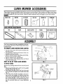
MOWERACCESSORIES
These accessories were available when this lawn mower was produced. They are also available at most Sears
retail outlets, catalog and service centers. Most Sears stores can order repair parts for you, when you provide
the model number of your lawn mower. Some of these accessories may not apply to your lawn mower.
ENGINE
,,,
SPARKPLUG
MUFFLER
AIR FILTER
, ..,.,,
............................
....:=::....
GASCAN
..................................
ENGINEOIL
STABILIZER
©
LAWNMOWERMAINTENANCE
BELT
BLADE
BLADEADAPTER
WHEEL5
LAWN MOWERCOVER
l
ASSEMBLY
tory except for the Grass Catcher Bag and the Grass
Catcher Frame.
CONTROL
BAR_
TO REMOVELAWNMOWERFROMCARTON
"_/
•
Cut down the corners of the carton and lay ends
and sides down.
•
Cut the plastic wrapping and remove from over
Handles and lawn mower.
Remove Catcher Frame, Fabric Bag and Oil Bottle from on top of lawn mower.
Remove Engine Cover and discard.
Lift lawn mower off of shipping base and check
carton for loose parts_
•
•
•
HANDLE
KNOB_
,'_
"V.
LOV_ER
/
HA\DLE
_
, ,."
, "'-"
L,_T
u_f_;_-::_.?L:,Y:'.::,".
'b" • LX
=0_ " 3",.
HOW TO SET-UPYOURLAWNMOWER
FIG. 1
TO UNFOLDHANDLE
HANDLE
BRACKET
Remove any packing material from around Control
Bars°
o Raise Lower Handle section until it is in the upright
storage detents (See Fig. 2).
• Raise Upper Handle section until it is in-line with
Lower Handle and tighten one Handle Knob (See
Fig. 1).
• Lower the entire Handle Assembly to the mowing position and engage the Height Adjustment
Links onto the Handle Bracket Pins (See Fig 2)o
See "Adjust Handle" section, page t6 to select
the most comfortable Lawn Mower Handle position. Be sure both sides are in same adjustment
hole_
OETENTS
HEIG
ADJUSTMENT
LINK
FIG. 2
'll '1
ASSEMBLY
...................
ill,iiiiii i
.......................
III
I
III1,1,1,111
I
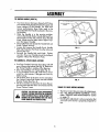
TO UNFOLD HANDLE (CONT'D)
iiiiiiiii
•
Your lawn mower has been shipped with Protective Handle Padsplaced between the upper and
lower sections or the Handle. For best lawn
mower performance these Pads need to be
discarded after the Handle is placed in the mowing position°
= Once the Handle is in the mowing position,
remove the Handle Knob, Handle Bolt and Protective Pad from the side with the loose Handle
•
°
°
IIII
CATCHER
HANDLE
Knob. (Make sure the other' side is tight to support the Upper Handle).
Discard the Pad and reinstall the Handle Bolt and
FRAME
O_ENING
IIII IIlll
Knob--Tighten securel/.
Loosen and remove the Handle Knob, Handle
Bolt and Protective Pad from the other side and
discard the Pad°
Iii,rl1,111,1,
MI'I I lllll
Ill
rl,lll i i
DOOR
L"
I'1'111
'111
III
GRASS
\
FRAME
TO ASSEMBLE
& ATTACHGRASSCATCHER
CATCHEt
FRAME
SiDE HOOK
•
CAUTION: DO NOTRUN YOURLAWNMOWER
WITHOUTCLIPPINGDEFLECTOR
OR APPROVED
GRASSCATCHER
IN PLACE.NEVERATTEMPTTO
OPERATE
THELAWN MOWERWITH THEREAR
DOOR REMOVEDOR PROPPEDOPEN.
IIITI'III'I
FIG. 3
Reinstall the Handle Bolt and Knob-. Tighten
securely° Now your Handles should be clamped
together without the Protective Pads.
Put Grass Catcher Frame into Grass Bag with stiff
part of Bag on the bottom (See Fig. 3). Make sure
the Frame Handle is outside of the Bag top.
• Slip vinyl bindings over Frame (See Fig_ 3)_
= Jf vinyl bindings are too stiff, hold them in warm
water for a few minutes, tf Bag gets wet, let it dr,i
before using.
° Lift the Rear Door of the lawn mower and place
the Catcher Frame Side Hooks onto the Handle
Bracket Hooks (See Fig_ 4).
• The Grass Catcher is secured to the Lawn Mower
Housing when the Rear Door is lowered onto the
Grass Catcher" Frame_
II I
BRACKET_
FIG. 4
THINGSTO CHECKBEFORE
MOWING
*
*
*
The Drive Control has provisions for adjustments,
See "TO ADJUST DRIVE CONTROL"
section
under "SERVICE AND ADJUSTMENTS"
section
on page 15.
Checking this adjustment is only a precaution that
your new lawn mower is properly prepared for
use.
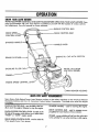
KNOWYOURLAWNMOWER
READ THIS OWNER'S
MANUAL
AND
SAFETY RULES BEFORE OPERATING
YOUR LAWN
MOWER_ Com_
andPareadjustments.the
illustratiOnSsaveWiththis
y°urmanualLawnforM°werfuture
tOreferenceofamiliarize
yourself with the location of various controls
!NE CONTROL
DRIVE
DRIVE
CONTROL
STARTER
CONTROL
BAR
LEVER
HANE
HANDLE
GRASS
BAR
EN(_INE
CATCHER
GASOLINE
KNOB
FILLER
OIL CAP WITH
DIPSTICK
WHEEL ADJUSTER
ON EACH WHEEL}
PRIMER
ENGINE
SPEED CONTROL
[
LAWN
MOWER
HOUSING
FIG. 5
MEETSCI C SAFETY
REQUIREMENTS
Sears Rotary Walk-Behind Power Lawn Mowers conform to the safety standards of the American National
Standards Institute and the U,,S. Consumer Product Safety Commission.
The blade turns when the engine
is running. inr,.r ,............................
......................
ENGINE
CONTROL
BAR. must be held'to the han-
..................
III'1'I I
STARTER HANDLE
I
II'll
- used for starting the engine_
dle to start the engineL Release to stop the engine_
ENGINE
SPEED CONTROL
LEVER - located on the
left side of the engine which allows you to selecteither
"HIGH"
or "LOW"
engine speed.
DRIVE SPEED CONTROL LEVER- used to select the
drive speed of your !:_wn mower°
DRIVE CONTROL
propelled forward
BAR - used to engage powermotion of lawn mower.
PRIMER - pumps additional fuel from the carburetor
to the cylinder for use when starting a cold engine°
OPERATION
•.
iiii ....................................................................
.......................
"'
""!'
HOW TO USEYOURLAWNMOWER
!'
'!'
I
II1,11',,'1
!'.
I
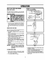
ENGINESPEEDCONTROL
The engine speed is controlled by a lever (red knob)
located on the right side of the engine (See Fig. 6).
ENGINE ZONE CONTROL
..........
CAUTION: FEDERAL
REGULATIONS
REQUIREAN
ENGINECONTROLTO BE INSTALLED
ON THIS
LAWN MOWER IN ORDERTO MINIMIZE THE
d_
RISK OFANY
BLADECONTACTINJURY.
DO NOT
UNDER
CIRCUMSTANCES
ATTEMPTTO
DEFEATTHE FUNCTION OF THE OPERATOR
CONTROL.THEBLADE
TURNSWHENTHEENGINE
IS RUNNING....
FIG. 6
Your lawn mower is equipped with an Operator
Engine Control Bar' which requires the operator
to be positioned behind the Lawn Mower Handle to start and operate the lawn mower' (See Fig.
DRIVE SPEED
SELECTOR LEVER
9).
GROUNDDRIVEFOURSPEEDS
Your lawn mower provides four (4) speeds to let you
select the speed that suitsyou best.,
• Your' engine is equippedwith a Variable Speed
Throttle,
•
The Drive Speed Selector' Lever can be changed
while you are mowing.
• Speeds I and 2 are found when the Engine Speed
Control (red) Lever is set between "HIGH"
and
"LOW"
positions (See Figs. 6 & 7),
. Speeds ! and 2 are for slower', light grass cutting, trimming and _quietoperation.
• Speeds 3 and 4 are found when the Engine Speed
Control (red) Lever is in "HIGH"
position (See
Figs, 6 & 7).
= Speed 3 is for"slow, heavy/thick grass cutting or
trimming°
• Speed 4 is for normal cutting and bagging and
for' ground transport.
IMPORTANT: DO NOT ATTEMPT TO SHIFT SPEEDS
WITH THE DRIVE CONTROL
BAR
ENGAGED UNLESS THE ENGINE IS
RUNNING_
, i
FIG. 8
*
The _round speed may be selected either when
standing or moving.
'
, To start forward motion, slowly pull up Drive Control Bar to the Handle (See Fig. 8)_
o To slow or stop forward motion tet the Drive Controt Bar move forward away from Handle,
, To stop forward motion release Drive Control Bar
(See Fig_ 8).
TO OPERATE
DRIVESYSTEM
',
•
Ir"'!.............. I',11
Select ground speed by moving Drive Speed
Lever to 1-3 or 2_4 position and selecting either'
HI or LOW engine speed,
1-3 is slower and 2-4 is faster_
8
OPERATION
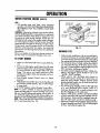
TO OPERATEDRIVESYSTEM
(CONT'D)
ENGAGED
D_SENGAGED
)SLTION
POS)TIC
By slightly releasing the Drive Control Bar, the
Drive can be slowedor "feathered"
so you may
make turns around obstacles or at end of rows
(See Fig. 8).
(ENGINE
TO EMPTYGRASSCATCHER
o To remove Grass Catcher, release Engine Control Bar to stop engine (See Fig, 9).
o Lift up Rear Door and remove the Grass Catcher
by the Handle.
* Emp_ty by_ shaking Catcher with open end
downward (See Fig. 10)_
NOTE: Do not drag the Bag when emptying; it will
cause unnecessary wear_
ENGINE
FIG. 9
TO ADJUSTCuI"rlNGHEIGHT
Raise Wheels for low cut and lower Wheels for
high cut.
Wheels are set in a tow cut for shipping. Adjust
cutting height to suit your requirements. Medium
position is best for most lawns.
o To change cutting height, squeeze Adjuster Lever
toward Wheel. Move Wheel up or down to suit
your requirements° Be sure all Wheels are in the
same setting (See Fig_ 11)_
*
BEFORE
STARTHNG
ENGHNE
FIG. 10
OIL:
A 20 oz= bottte of Pennzoil SAE 30 Oil is included
with your new lawn mower°
• Remove Engine Oil Cap with dipstick (See Fig.
12) and fill to the FULL line on the dipstick°
• Use 20 ozs. of SAE 30 oi!. SAE 10W 30 oil can
also be used.
o POUR OIL SLOWLY° DO NOT OVERFILL°
• Check oil level before each use. Add oi! if needed. Fill to FULL line on dipstick.
= To read proper level, tighten Engine Oil Cap each
time.
,, Reinstall Engine Oil Cap and tighten.
o After the first two (2) hours of mowing, change
the oil, and every 25 hours thereafter. You may
need to change the oil more often under dusty,
dirty conditions_
FIG. 11
CONTROL
STOP)
BAR
II
ii
"_'_'_'_
_....
i
ii II
'111'111
I
...........................
OPERATION
I' I
II'111
.........................................................
..................
BEFORE
STARTING
ENGINE(€ONT'O)
.....
GAS:
• Fill gasoline tank with fresh, clean unleaded
gasoline. DO NOT USE PREMIUM GASOLINE.
BE CAREFUL NOT TO OVERFILL TANK (SEE
FIG. 12)_
WARNING: Experience indicates that alcohol blended fuels (called gasoho! or using ethanol or methanol)
can attract moisture which leads to separation and
formation of ac:ids during storage. Acidic gas can
damage the fuel system of an engine while in storage.
To avoid engine problems, the fuel system shouidbe
emptied before storage for' 30 days or longer. Drain
the gas tank, start the engine and let it run until the
fuel|ines and carburetor are empty. Use fresh fuel
next season. See Storage Instructions for additional
information.
MOWINGTIPS
Never use engine or carburetor cleaner products in
the fuel tank or permanent damage may occurs.
•
Make sure Fuel Shut-Off Valve is open (See Fig_
•
To start a cold engine, push Primer five (5) times
before trying to start. Use a firm push being sure
to cover the hole in the Primer Bulb with your
finger. This step is not usually necessary when
starting an engine which has already run for a
few minutes°
Ill
OIL FILL CAP
WtDIPSTtCK
IIIl!lIJI
ENGINE SPEED
CLEANEE
FUEL
TANK
GASOLINE
FiLL CAP
SHUT-OFF
VALVE
FIG. 12
Under certain conditions, such as very tall grass,
it may be necessary to raise the height of cut and
lower' the ground speed to keep from overloading
the engine and leaving clumps of grass clippings.
• For extremely heavy cutting, reduce the width of
cut and raise the rear of the lawn mower housing one (1) wheel adjustei' setting higher than the
front for better discharge ofgrass_
o For better grass bagging andmost cutting conditions, the engine speed should be set in the
"HIGH"
(FAST) position.
° When using a rear discharge lawn mower in
moist, heavy grass, clumps of cut grass may not
enter the grass catcher. Reduce ground speed
(pushing speed) and/or run the lawn mower over
the area a second time.
° if a trail of grass clippings is left on the right side
of a rear discharge lawn mower, mow in a
clockwise direction with a small overlap to collect the clippings on the next pass.
° Pores in cloth grass catchers can become filled
with dirt and dust with use and catchers will cotled less grass. To prevent this, regularly hose catcher off with water and let dry before using.
° Keep top of engine around starter clea_and clean
of grass clippings and chaff. This will help engine
air flow and extend engine life.
TO STARTENGINE
•
MLL'I
t2)
•
Push Engine Speed Control Lever to HIGH
position°
Hold Engine Control Bar down to the Handle and
pull Starter Handle quickly. Do not allow Rope
to snap back.
• To STOP engine, release Engine Control Bar,
NOTE: tn cooler weather it may be necessary to
repeat priming steps. In warmer weather over"priming may cause flooding and engine will not start, tf
you do flood engine wait a few minutes before attempting to start and DO NOT repeat priming steps.
NOTE:Close Fuel Shut-Off Valve when equipment is
not in operation (See Fig. 12).
10
MAINTENANCE
GENERAL
RECOMMENDATION
o Once a year you should replace the Spark Plug,
clean or replace Air Filter and check Blade for
wear. A new Spark Plug and Air Filter assures
proper air-fuel mixture and helps your engine run
better and tast longer°
• You should check all fasteners and be sure they
are tight.
° Follow the Service Recommendation Schedule on
LOCKWASHER
page 18_
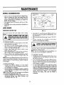
LAWNMOWER
CRANKSHAFT
KEYWAY
BLADEIBLADE
ADAPTERCARE
Your lawn
Blade.
/1111111111111
i
iii
iiiii
mower
iiiiiii
will work
FIG. 13
better with a sharp
°
iiiiiiiiiiiiiiiiiii
CAUTION: DISCONNECTSPARKPLUG WIRE
FROMSPARKPLUGAND PLACEWIRE WHERE
IT CANNOTCOMEIN CONTACT
WITHTHESPARK
PLUG.
lliH
•
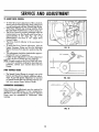
Use block of wood between Blade and Lawn
Mower Housing and tighten the Blade Bolt, turning clockwise.
The recommended tightening torque is 35-40 ft
Ibs.
o Torque wrenches are available
stores and through the catalog.
HHHHll
TO REMOVE BLADE:
• Turn lawn mower on its side° Make sure Air Filter
and carburetor are down.
o Use block of wood between Blade and Lawn
Mower Housing to prevent Blade from turning
when removing the Blade Boll
,, Protect your hands with gloves and!or wrap
Blade with heavy cloth.
o Remove Blade Bolt by turning counter-clockwise°
Use a 9/16" box or open-end wrench_
o Remove Blade and attaching hardware
(Bolt,
Lockwasher and Hardened Washer) (See Fig,
13).
NOTE:Remove the Blade Adapter and check the Key
inside Hub of Blade Adapter.
The Key must be in
good condition to work properly. Repface Adapter
if damaged.
.................................
i
at most Sears
i
AND
MAY MAKETHEENGINEHARDTO
START.
CAUTION:A
LOOSEBLADECANBEDANGEROUS
Use only a Sears authorized replacement Blade to
get the best cutting results.
NOTE: We do not recommend sharpening Blade ° but
if you do, be sure the Blade is balanced.
TO SHARPEN BLADE:
,, The Blade can be sharpened with a file or on a
grinding wheel. Do not attempt to sharpen while
on the lawn mower.
o Care should be taken to keep the Blade balanc*
ed_ An unbalanced
Blade will cause excessive
vibration when running and eventual damage to
lawn mower or engine°
"
o To check Blade balance, drive a nail into a beam
or wall. Leave about one inch of the straight nail
exposed. Place center hole of Blade over the head
of the nailo tf Btade is balanced, it should remain
in a horizontal positiom If either end of the Blade
moves downward,
Blade is not balanced°
Sharpen
the heavy end until the Blade is
balanced.
TO REPLACE BLADE:
o Position the Blade Adapter
on the engine
crankshaft. Be sure Key in Adapter and Keyway
in Crankshaft are aligned.
o Position Blade on to the Blade Adapter aligning
the two (2) holes in the Blade with the raisedLugs
on the Adapter.
NOTE: Be sure the word TOP (stamped on the Blade)
is toward the engine (See Fig. 13).
• Install the Blade Bolt with the Lockwasher and
Hardened
Washer
into Blade Adapter
and
Crankshaft (See Fig. 13).
11
MAINTENANCE
DRIVEWHEELS
II
Check Rear Drive Wheels each time before you mow
to be sure they move freely_ The Wheels not turning
freely means trash, grass cuttings, etc., are inside the
Drive Wheel and Dust Cover area and mustbe cleaned out to free Drive Wheels.
iliH
WASHER
HAIRPIN
COTTER
DRIVE
PAWL
DUST COVER
If necessary to clean the Drive Wheels, check both
Rear Wheels (See Fig. 14).
Remove Hubcaps, Hairpin Coffers and Washers.
• Remove Wheels from Wheel Adjuster Axtes_
• Remove any trash or grass cuttings from inside
the Dust Cover, Pinion and/or Drive Whee; Gear
Teeth.
PINION
ASHER
CAP
rl
'IIII
I"
FIG. 14
•
If you remove the Drive Pinion and Drive Pawt,
reter to fig_ 15 for correct assembly of Drive Pawlo
,p The Pinion Gear must be installed with the Left
Gear" on the left side and the Right Gear on the
right side, from an operator's
view.
• The Pinion Gear is stamped with an "L" (Left) or
"R" (Right) on the inside. If installed incorrectly,
the Drive System will not work.
• Place Wheels back on Adjuster Axles.
• Replace Washers, Hairpin Coffers and Hubcaps.
NOTE:Pinionsand Drive Pawls should be cleaned and
lubricated with spray lul_ricant approximately every
25 hours_
TOP OF MOWER
FRONT OF MOWER
DRIVE SHAFT __
DRIVE PAWL
GRASS
CATCIK'R
....
,ll,
......................
FIG. 15
The Grass catcher may be hosed with water, but
must be dry when usod.
Check your Grass Catcher often far damago or
deterioration. Through normal use it wi|l wear.
If C_cher needs repla_cing, replace onty with a
manufacturer
choproved replacement Catcher
from Sears_ Give the lawn mower model number
when ordering L
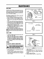
ENGINE
TO CHANGEOIL (WARM OIL DRAINSBETTER)
..................
:
: ....
:
,i i i
i ii L
,.i
ii
CAUTION: DISCONNECT
SPARKPLUGWIREFROM
d_
SPARKPLUGANDPLACE
WIREWHEREITCANNOT
COMEIN CONTACTWITH SPARKPLUG.
o
Remove Engine Oil Cap with dipstick; lay aside
on a clean surface_
o
Tip lawn mower on its side as shown in Fig. 16
and drain oil into suitable container. Rock lawn
FIG. 16
•
Wipe off any spilled oil on lawn mower and on
side of engine_
• Fill engine with SAE 30 or 10W 30 oil, fill only
to the "FULL"
line on the dipstick. DO NOT
overfill.
• Replace Engine Oil Cap.
• Reconnect Spark Plug Wire to Spark Plug.
mower back and forth to remove any oil trapped
inside of engine.
12
TENANCE
AIR FILTER
..................................................................................................................................
_.............
BACK
Clean or replace Air Filter every 25 hours or every
season, whichever occurs firsL
NOTE: Service Air Filter more
conditions,
TO CHANGE
o
o
CARTRIDGE
LIP
often under dusty
AIR FILTER
Loosen Screw and tilt Cover as shown in fig. 17.
Carefully remove Cartridge.
Clean by tapping gently on a flat surface. If very
dirty, replace Cartridge or clean as follows:
Wash in a low or non-sudsing detergent and
warm water solution. Rinse thoroughly with flowing water from mesh side until water runs clear.
Let Cartridge air dry thoroughly before using.
I
I
t
I
LLJJJIIIII
IIIIIIIII
UII
I
II
II
I
I
III
II
I
FIG. 17
CLEANING
UIIIIIIII
CAUTION:PETROLEUM
SOLVENTS,
SUCHAS
KEROSENE,
ARENOT TO BEUSEDTO CLEAN
We recommend that you clean the underside of your
lawn mower after each use.
TIONOFTHECARTRIDGE.
CARTRIDGE.
THEYMAY CAUSE
DO NOTOIL
DETERIORACARTRIDGE.DO NOT USEPRESSURIZED
AIR TO
CLEANOR DRY CARTRIDGE.
•
LATE
CAUTION: DISCONNECTSPARK PLUG WIRE
FROM
SPARKPLUGAND
PLACEWIRE
IT CANNOT
COME IN CONTACT
WITH WHERE
SPARK
PLUG.
lnstalt Cartridge, then replace Cover making sure
the tabs are aligned with the slots in Back Plate.
Fasten Screw securely (See Fig. 17)°
_' Turn lawn
down
mower
on its side with Carburetor
o
', Clean the underside of your lawn mower by
scraping to remove build-up of grass and trash°
,, Clean your lawn mower and engine often to keep
trash from accumulating around engine. A clogged engine runs hotter and shortens engine llfe.
SPARK PLUG
Change your Spark Plug each year to make your
engine start easier and run better_ Set Spark Plug
gap at °030 inch.
NOTE: We DO NOT recommend using a garden hose
to clean lawn mower unless the Electrical System,
Muffler, Air Filter, and Carburetor are covered to
keep water out. Water in engine can result in shortening engine life.
13
I'111111'1,',1'
II1'
'............................
' ......................................
_lJ__
SERVICE
ANDADJUSTMENT
II
.............................
TO REMOVE/REPLACEDRIVE BELT
I
'"'"'""""'
............................
'
/l'_/Irl'lllll'l
IH'l
I'1
I1'1111 III
I
I"1'1111
iii, i, _, , ,
CAUTION: DISCONNECTSPARK PLUG WIRE
FROM SPARKPLUGAND PLACEWIRE WHERE
IT CANNOT COME IN CONTACTWITH SPARK
PLUG.
REAR
,,,,,_,,
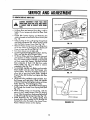
Lift Rear Door and remove Grass Bag, it will be
helpful if you temporarily block the Rear Door
open_
Locate Belt Tension Spring and Retention Pin
which is located on back side of lawn mower (See
Figr
DOOR
RETENTION
:ACCESS
COVER
1 B),
Using a piece of wire, pull Spring through hole
and remove Retention Pin° Allow Spring to slide
into the Plastic Access Cover' (See Fig_ 18)o
Remove Plastic Access Cover by pushing down
on its top surface to disengage Top Hooks_pull
Cover to rear and lift up (See Fig. 19).
Turn lawn mower' on its right side.
Loosen Engine Bolt holding Belt Snubber. See Fig
20A, and slip Belt off of Engine Pulley.
Tilt Driven Pulley and Drive Assembly rearward
until Locknut on Pulley Assembly is visible (See
Fig. 19). Loosen Locknut until Belt can be slipped
out from under Belt Keeper_ Slip Belt forward
from underside of Deck. Pull Belt from under
Plastic Baffle and slip over' Blade to remove
completely (See Fig° 20).
To install Belt, slip Belt over Blade, push up under
Plastic Baffle and slip under Belt Keeper onto
Driven Pulley. Tilt Drive Assembly forward to
allow Belt to seat into Engine Pulley. Readjust
Engine Pulley Belt Snubber and tighten Bolt (See
Fig_ 20A).
FIG. 18
FIG. 19
i,i1' , II1,1
Tilt Driven Pulley until Belt is tight and holdo Turn
Belt Keeper until right side is flush with outside
of Access Opening, and tighten Locknuton Driven
Pulley (See Fig, 19 and Diagram 19A).
Using a piece of wire, pull the Belt Tension Spring
End through the Access Cover Spring Hole 'ISee
Fig° 19)_
•
While holding tension on the Spring, with the
piece of wire, install Access Cover by placing
Lower Tabs into position. Make sure Spring End
is pulled through the Spring Hole (See Fig_ 19).
ORtVE
BELT
\
O_IVEN
PULLEY
ACCESS
lnstall Retention Pin by pulling Spring End
through hole while slipping the Pm through the
Spring End so the Pin seats in the Access Cover
Pocket. Release tension on the Spring.
OPENING
DIAGRAM19A
14
ST
......
ii,l,,i,,i
....................
i ,,,i ,, i
, ,
i
,
_.......
1'
,
...............
,,
_
, , ,J
.........................
_,_
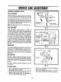
TO ADJUST DRIVE CONTROL
o To check for proper adjustment of Drive Control,
slowly pull up on the Drive Bar while pulling lawn
mower backwards until Rear Wheels stop turning.
• When Rear Wheels stop turning, hold the Drive
Bar and check the dimension as shown in fig. 21
o The Drive Control is properly adjusted when the
measurement over the Handle and Drive Bar is
approximately
3 1/2" (See Fig. 21)° If the
measurement is less than 3 1/2" adjust Drive
Control Cable°
•
•
The Drive Control Adjuster is the one closest to
operator_
To make the Drive Control adjustment, hold the
Upper Hexagon Fitting and turn the Adjusting
Sleeve clockwise from operator position (See Fig
FIG, 20
22),
•
This adjustment should be checked after approximately 25 hours of operation.
o if after several adjustments no further adjustment
is left, the Drive Wheel must be replaced°
NOTE:Through normal use the Drive Wheel wilt wear**
• if you have problems making the described adjustments, contact your nearest Sears Service
Center°
BELT SNUBBER
'.,
k,
._,,1"
APPROX
_'_"_
//
ENGINE
MOUNTING
BOLT
1 32
SPEEDCONTROLRANGE
The Speed Control Range is properly set at the
factory and should not requireadditional
adjustment. Ifyou feel Speed Adjustment is incorrect
or Speed Control does not operate properly contact your nearest Sears Service Center.
FIG. 20A
UPPER
CARBURETOR
ADJUSTMENTS
Minor Carburetor
adjustment may be required to
compensate for differences
in fuel, teml_erature,
altitude or toad. The Air Cleaner and Air Cleaner
Cover must be assembled to Carburetor
when
running_
DRIVE BAR
ENGINE
CONTROL
BAR
FIG. 21
15
l_J
.........
II
I'll
i1,,11
1,1,11111
II
,
,lllllllllllIll
...............................................
SERVICE
ANDADJUSTMENT
...........
II II
IJlll II
'"11'1'111111
J'l
I'lL
!111111'11
Ill
............
!'
I,II,I
CARBURETOR
ADJUSTMENT
(CONT'D)
UPPER
.....................
I1!1
_;_
III
HEXAGON
FITTING
INTIAL ADJUSTMENT:
_" "\ CONTROL
With the engine not running,
gently turn idle Mixture Screw do&wise until it just closes. Screw ma)_
be damaged
II1'11'1
II_
DRIVE
CONTROL
by turning it in too far (See Fig. 23)_
CABLE
Next open the Screw one turn counter-ctockwiseo This
initial adjustment will permit the engine to be started
and warmed up (approximately 5 minutes) prior to
final adjustment (See Fig. 23)_
,_k-,"UPPE
R HEXAGON
ADJUSTER
SET AT FACTORY
NOTE:DO NOT adjust top no load adjusting Screw°
(Pre-set at Factory).
'i"'
Ill'Ill'
'1
FIG. 22
'FINAL ADJUSTMENT
I
Place Equipment
Control
Lever in "IDLE"
or
"SLOW"
posifion_ Adjust idle RPM, by turning Idle
Speed Adjusting Screw to obtain 1400 RPMo Next,
turn Idle Mixture Screw in (clockwise - lean mixture)
until engine just starts to slow. Then turn idle Mixture Screw out (counter-clockwise - rich mixture) until engine runs unevenly. Now turn idle Mixture
Screw midway between rich and lean. Engine should
accelerate smoothly. If engine does not accelerate
properly, the Carburetor should be readjusted,
usually to a slightly richer mixture, by turning the idle
Mixture Screw counter-clockwise 1/8 turn more (See
Fig_ 23)_
................
Ill'I'll'Ill
TOP NO LOAD SCREW
IDLE SPEED
ADJUSTING
SCREW
IDLE
MIXTURE
SCREW
ENGINE SPEED
FIG. 23
Your engine speed has been factory set. Do not attempt to increase engine speed or it may result in personal injury, if you believe that the engine is running too fast or too slow, take your lawn mower' to
an authorized Sears Service Center for repair and
adjustment.
LOWER
HANDLE.._%
HANDLE
_T
PIN
REAR DEFLECTOR
The Rear Deflector, attached between the Rear'
Wheels of ycourlawn mower, is provided to minimize
the possibility that objects wilt be thrown out the rear
of the lawn mower into the operator's mowing
position°
If the Rear' Deflector
be replaced.
becomes damaged,
ADJUSTI
LEVER
it should
FIG. 24
TO ADJUSTHANDLE
I
"
•
•
Grass bag should be removed temporarily
for
easier adjustment of Handle.
The Handle on your lawn mower has three (3)
suits you.
To adjust the Handle, push in on
Adjusting
heights - adjust to the height that _h_)
Levers to clear the Pins (See Fig.
.
I
16
Raise or lower Handle and position the Adjusting
Levers on to the Pins.
Be sure that Handle Bracket Pin is in the same
Lever Hole on both sides of the lawn mower.
STORAGE
Your lawn mower and engine should be prepared
for off-season storage as follows:
LAWN MOWER
o Clean underside of Lawn Mower Housing° (See
"Cleaning"
in maintenance section of manual°)
o Inspect and replace/sharpen Blade, if required
(See
"Blade/Blade
Adapter
Care"
in
maintenance section of manual).
o Hose Grass Catcher off with water and let dry
before storing°
o Lubricate as shown in Service Recommendation
chart on page 18 of manual.
HANDLE
e You can fold your Lawn Mower Handle for
storage as shown in Fig. 2&
o To fold, push in on the Adjusting Levers to clear
the Pins, then move Handle forward (See Fig. 24).
IMPORTANT: WHEN
FOLDING
THE HANDLE
FOR STORAGE OR TRANSPORTATION, BE SURE TO FOLD THE HANDLE AS SHOWN IN FIG. 25. IF YOU
FOLD THE UPPER HANDLE
SECTION THE WRONG
WAY,
YOU
MAY
DAMAGE
THE CONTROL
CABLES°
OTHER
o Do not store gasoline from one season to another.
o Replace your gasoline can if your can starts to
rust. Rust and/or dirt in your gasoline can cause
probtems_
• Do not store your lawn mower under any plastic
cover_ Plastic cannot breathe which allows condensation to form and can cause your lawn
mower to rust.
,, When setting up your Handle from the storage
position, the Lower Handle will require manually locking into the mowing position.
ENGINE
o Change oil (See "To Change Oil" in maintenance
section of manual).
• Drain fuel and run engine until fuel system is
,TJs,MPORTANT
TOPREVENT
GUM
DEPOS,TS
FROM
FORM,NG
IN ESSENTIAL FUEL SYSTEM PARTS
SUCH AS THE CARBURETOR, FUEL
FILTER, FUEL HOSE, OR TANK DURING
STORAGE
ALSO,
EXPERIENCE INDICATES THAT ALCOHOL
BLENDED
HaL OR
FUELS (CALLED GASOUSING
ETHANOL
OR
METHANOL)
CAN ATTRACT MOISTURE WHICH LEADS TO SEPARATION AND FORMATION
OF ACIDS
DURING
STORAGE. ACIDIC GAS
CAN DAMAGE THE FUEL SYSTEM
OF AN
ENGINE
WHILE
IN
STORAGE°
17
'1{'{
'
1{1'
{
1'
'1'{'1{{{
{
111
'
{'11{II
.................................................
1{!{I
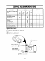
SERVICE
RECOMMENDATIONS
IIIIII,,
S£RVICE
RECORD
Fill in dates as you camp{ere
service
SERVICE
DAT_
SCHEDULE
regu{ar
First
2
Hours
Every
10
Every
25
Hours
Every
Use
Hours
Blade Checked
Engine Oil Change
Engine Oil Check
Air Cleaner
Spark P,ug Repl;ced
t,,"
Lubricate Lawn Mower
....
=
Cleaning
..........................
..............................
Grass Ca,,!cher(if applicable)
Drive Pinions and Drive Pawls
II1,1111IIIIIII1'11,1
I II
II
I III'
/,_
......................
.........
_
........
IIII IR'I, I
LUBRICATION
CHART
Q
SAE 30
MOTOR
OIL(lOW
(_
SPRAY
LUBRICANT
30)
ENGINE
HANDLE
MOUNTING
DRIVE
BRACKET
PIN
PINIONS
DRIVE
L ADJUSTER
18
OIL
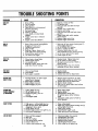
TROUBLE
SHOOTING
POINTS
CAUSE
PROBLEM
i
i
CORRECTION
u u ..u.u.,
........................................
DOESFlat
STAi_
1.
2_
3.
4,
Dirty air'liter.,
Out of gasoline
Stale gasoline
Spark plug wire is disconnected
from the spark plug,
5, Bad spark plu_
6_ Water in gasotine_,
7., Loose blade or broken blade
adapter,
8,,
Engine control bar in released
position
9,
Engine control bar defective,
, Replace
or clean
_,
Fill gasoline
tank. air filter,
3. Drain gas tank and refill with fresh
gasoline_
4, Connect wire to spark plug
5_ Replace spark plug,
6 Drain tank and refill with fresh, clean
gasoline,
7_ Tighten blade bolt andlor replace
blade adopter,
8, Depress engine control bar
9 Replace engine control bar,
LOSSOF
POWER
1_ Rear of lawn mower housing/blade
dragging in heavy grass
2, Cutting leo much grass,
1. Raise rear of lawn mower housing one (1)
setting higher than front.
2o Set in HIGHER CUT position.
3, Clean or replace air filter_
4 Disconnect spark plug wire and
clean underside of lawn mower housing
5 Cut at slower ground drive speed_
6 Check engine oil level,
air filter
o, Dirty
Build_upof
grass, leaves, and
trash under lawn mower housing
5_ Ground drive speed too fast
6_
Too much oil in engine,
rl
POORCUT.
UNEVEN
Worn, bent or loose blade_,
Wheel heights uneven_
3_
Low engine speed,
4o Build-up of grass, leaves and trash
under lawn mower housing.
1. Replace blade Tighten blade bolt,
2, Set all wheels at same height
3 Set engine speed control in FAST or
HIGH position,
4, Disconnect spark plug wire & clean
underside of lawn mower housing,
TOOMUCH
VIBRATION
,
Worn or bent blade°
2.
blade,crankshaft,
3_ Loose
Bent engine
1_ Replace blade.
Tighten blade boll,,
2o Contact Sears Service Department_
ST_P:,.RROPE
HARDTO PW.L
Flywheel brake is on when engine
control bar is released,
,, Bent engine crankshaft,
3, Blade adapter sheared,
4_ Blade dragging in grass°
to Depress engine control bar to upper
handle before pulling on starter rope
2. Contact Sears Service Department
3, Replace blade adapter.
4_ Get over low grass and!or hard surface
to start engine_
_TatER HOT
FIU,INg_Y
1o Cutting height too low.
2. Lift on blade worn off°
3, Catcher bag dirty, poor air
ventin 9
,_. Low _glne speed_
1,, Raise cutting height,
2, Replace blade,
3,
Clean/replace catcher bag,
(If optional gross catcher is being
i
(tr AeeU_m)
i
used).
4, Set engine speed control in FAST or
HIGH position_
II
LOSS
OFDRIVE
II
JII
I
I
II'
I
........
i
High grass or cutting height too low,
Rear of lawn mower housing_lade
dragging i_theavy grass,
,, GFal_ catcher too full
4_ Handle height position not right for you,
5_ Drive pawls hanging-upo
t_ Raise cutting height°
2_ Raise rear of lawn mower housing one (1)
setting hlgh_r tha'n front_
3_ Empty grass catc:her.
4o Adjust handle height to suit,
5 Cleon drive pawls and tubricate_
1,
2_
3,
4o
5.
6
1,
2_
3.
4,
5.
6,
Drive not fully engaged,
Belt wear°
Belt off of pulleys_
Lost spring tension retainer
Friction wheel worn
Friction wheel excessively wet°
19
Check and adjust drive control
Check/replace drive belt,
Check/reinstall drive belt_
Replace spring retainer,
Check/replace friction wheel,
Allow wheel to dry before use_
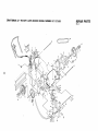
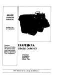
CRAFTSMAN
22"
ROTARY
LAWN
MOWER
MODEL
NUMBER
917.372451
REPAIR PARTS
Rev. 2
\
0
\
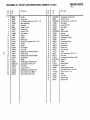
CRAFTSMAN
22"
ROTARY
LAWN
MO_F=R
MODEL
NUMBER
REPAIR PARTS
917.372451
Rev. 2
Part
No.
Part Name
8
9
10
1t
!2
751608
STD541425
751150
751040
750629
751801
86055
851185
751584
751385
751152
751053
13
14
15
16
17
18
19
20
2t
22
23
24
25
26
27
28
29
30
31
32
33
34
35
36
37
38
751625
751782
STD522515
85827
851000
87692
751305
750785
58714
66426
751638
750820
800445
800443
800444
STD541431
83923
800447
800469
750621
750619
750620
851639
750674
851552
750671
Engine Control Bar
Locknut 1/4-20
Drive Bar Decal
Drwe Bar
Upper Handle
Cable Pull
Machine Screw 114-20 x 2 t/4
Machine Screw 114 x 2 314
Screw #6-20 x 3/8
Spacer
Locknut 114-20
Drive/Speed
Control Cable Assembly
(See Page 24)
Spacer
Spacer
Hex Head Bolt 114-20 x 1 1/2
Cable Clip
Belt Snubber
Handle Knob
Instruction
Decal
Lower Handle
Handle Bolt 5/16-18 x 1 3/4
Wire Tie
Tube Bolt 5116-t8 x 1 3/8
Rope Guide
Handle Adjusting
Bracket
Handle Link (Left)
Handle Lu_k (Right)
Locknut 5/16-18
Locknut 3/18-16
Washer
Spacer
Door Handle
Spring (Right)
Spring (Left)
Seal Strrp
Rear Door
Pan Head Screw t0-16 x 1/2
Hinge Rod
Ref.
No.
...........................
1
2
3
4
5
6
t_
w_
iii,u
Ref.
No,
Part
No.
Part Name
39
40
41
42
851454'
750673
85463
48218
43
44
45
46
47
48
49
50
51
52
53
54
55
56
57
58
59
60
54583
88641
88642
84920
88348
87887
850863
77865
62335
84921
750507
52160
85179
77400
750675
750780
851219
850998
6t
62
63
64
65
STD54t437
751302
751303
87588
851084
66
67
68
69
70
7!
72
73
74
75
850263
851074
850973
851514
87677
84596
59708
751698
62509
750664
Wiper Strip
Hinge Bracket
Danger Decal
Lawn Mower Housing
(Incl. Ref. #41 & 64)
Hex Tapping Screw 114-20 x t/2
Wheel Adjusting Bracket (Right)
Wheel Adiusting Bracket (Left)
Spacer
Washer
Axle Arm Assembly
Selector Spring
Selector Knob
Belleville Washer
Shoulder Bolt 3/8-16
Wheel & Tire Assembtv 8.0 x 1 3/4
Washer
Retainer Clip
Hubcap
Catcher Frame
Grass Bag
Engine Washer
Hex Head Thread Rolling Screw
3/8-16 x 1 1/8
Locknut 3/8-16
Spec Decat
Housing Decal
Front Baffle
Hex Head Screw 3/8-24 × 1 3/8
(Grd. 8)
Helical Lockwasher 3/8
Hardened Washer
22" Blade
Blade Adapter
Hi-Pro #HP-505
Engine Pulley (Incl. Ref. #72)
Set Screw !/4-20
x 5/16
Engine Zone Control Cable
Truss Head Screw 1/4-20 x 1
Engine - Briggs/Stratton
Model No. 124702 Type No. 3121-01
Owner's Manual
i
I
751901
J l
ti iiil_tfl
CRAFTSMAN
22'" ROTARY
LAWN
MOWER
MODEL
NUMBER
REPAIR PARTS
917.372451
Rev. 2
3
/
t'o
P_
t9
CRAFTSMAN
22"
ROTARY
LAWN
MOWER
MODEL
NUMBER
REPAIR PARTS
917.372451
Rev, 2
Ref,
No.
Part
No.
Part Name
Ref.
No,
Part
No,
Part Name
1
2
3
4
5
6
7
8
9
10
11
12
13
14
15
16
17
t8
19
20
2!
22
23
24
25
26
27
28
29
88028
750697
86974
750692
53971
88349
700279
74189
750996
77400
52160
85179
751148
88446
67725
750818
750734
751094
77865
750810
750735
10102
750809
STD533107
750819
751153
751095
750320
750319
Roll Pin
Access Door
Hex Washer Head Screw 10-24 x 7/!6
Back Plate/Baffle
Speed Nut
Locknut 114-20
Retainer Clip
Locknut
t0-24
Rear Deflector
Hubcap
Washer
Retainer Clip
Wheel & Tire Assembtv 8.0 x 1 3/4
Bushing
Washer
Pinion (Right)
Dust Cover
Height Selector Assembly
(Right)
Selector Knob
Handle Bracket Assembly
(Right)
Shoulder Bolt
Washer
Handle Bracket Assembly
(Left)
Carriage Bolt 5116-18 x 3/4
Pinion (Left)
Locknut 5!16-18
Height Selector Assembly
(Left)
Seven Position Decal (Right)
Seven Position Decal (Left)
30
31
32
33
34
35
36
37
38
39
40
41
42
43
44
45
46
47
48
49
5O
51
52
53
54
55
56
57
58
59
60
61
STD532507
88349
STD522506
751899
750253
751888
750892
STD582062
750686
750684
751659
750680
750834
751071
750679
750732
750681
751133
84026
850018
751070
STD572515
52160
751232
STD560607
750688
48219
11142OX
751582
750991
751780
750841
Carnage Bolt 1/4-20 x 5/8
Locknut 1t4-20
Hex Head Screw 1/4_20 x 5/8
Belt Keeper
Locknut 5116-t8
Drive Spring
Spacer
Retaining Ring
Beanngs
Pulley Assembly
Compression
Washer
Stand Off
Compression
Spnng
Locknut 6-32
Oilite Bearing
Rocker Arm
Drive Housing
Clamp
Hex Thread Screw 10-24 x 112
Drive Pawl
Hex Washer Head Machine 6-32
Spring Pin
Washer
Sleeve Bearing
Cotter Pin
Wheel Assembly Friction
Dnve Shaft Kit (lncl, Ref. #53)
Bolt 5t16-18 x 3 1/4
Shield
Drive Belt
Deflector Rod
Deflector Rod
,,,, ,,,,,,,,,,,,,,,,,
,,,,
60
REPAIR PART-
CRAFT_IAN
22" POWER-PROPELLED
LAWN MOWER
917.372451
DRIVEtSPEED
CONTROL
CABLE
3
\
\
\
\
\
Ref_
NOo
Part
No.
Part Name
'1 '1
1
2_
3
4
5
6
7
8
9
10
48235
751837
751834
751828
751829
751830
751831
751840
751833
751832
IIIl'llql' I
'11 I1'11'11
I
-
Control Head Kit (tncl, Ref, #2
Ptastite Sc;_w #8 x 7t8
Torsion Spring
Drive Actuator
Drive Pulley
Speed Lever
Leve; Mounting
Plastite Screw
#4 x 5/8
Washer 118 x 3/8
Speed Cable Assembly
Drive Cable Assembly
24
[
LAWN MOWER
NOTE:
Change Engine OiL after the first
DATE
CARE RECORD
two
DATE
(2) hours of use, and then every
DATE
DATE
25 hours
DATE
DATE
Change Oil: SAE 30
or 10W30
Replaced
spark plug:
Replaced air filter:
Replaced
blade:
Tuned-up:
uuutIIIIH tii illlllll ilUlll
IJ/'t IIIJlll/I
J/llJlll mlHImUl.'_'_'"'
_ _'
l/
i'mm_
.....................
25
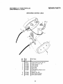
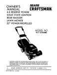
BRIGGS/STRATTON
4-CYCLE ENGINE
MODEL NO. 124702
TYPE NO. 3121-01
332
(_455
324
23
572
307
615,
230,
46
842
26
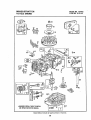
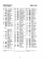
BRIGGS/STRATTON
4-CYCLE ENGINE
REF
NO,
1
2
PART
NO.
493260
293708
Note:
3
5
7
8
"'393862
213610
**272200
399717
9
*'271904
9A "'272238
10
94222
1t
231685
12
13
"'272t98
94547
15
16
93418
493362
18
20
22
23
24
25
493279
**399761
Note:
94220
MODEL NO. 124702
TYPE NO. 3121-01
DESCR)PTION
Cylinder Assembly
Bushing -Cylinder
Requires
special
for instaffation
tools
Scot-Oil
Head _Cyiinder
'
Gasket - Cyffndor
Breather--Valve
Chamber
Cover
Gasket-Baffle
Screw*Breather
PIate
Mounting
Sam
Tube--Breather
Screw
94526
Order 94388
Gear Key
For Timing
Sump _ Engine
Seal-Oil
Sam
Piston
Piston
Assy
Assy
-Standard
--010"
0 S
493386
Piston
Piston
Assy
Assy
--020"
_030-"
0 S
O S
Ring Set-Standard
Size_Order
Part
493261
Ring Set-Std,
493388
Ring Set-Piston
493389
Ring Set-020
Piston
493390
Ring Sat-,030"
Piston
94058
280973
Screw-Guard
Mounting
WasherRewind Starter
523
492350
69A
81
224322
223664
WasherRewind Starter
Lock-Muffler
Screw
524
525
280967
280929
Screw--Throttle
528
529
399254
280943
562
572
92613
224328
592
231082
601
93053
94098
104
116
398185
493280
"231371
"t
Pin-Float
Gasket-
Hinge
Seating
(Sold in Kit Only)
.Jet
"
1"_8
492945
t21
492495
124
94525
125
127
493627
*
130
131
223470
493267
133
! 34
398187
"398186
Note:
in Kit Only_
Valve and
Needle
Carburetor
Spring
Overhaul
Kit
Screw-Carburetor
Carburetor
Plug--Welch
t$old in Kit Only)
Valve -Throttle
Shaft and Lever-
Rod Assembly-
304
305
493293
94513
Housing-5crew-Hex
Connecting
For Connecting
Rod
with
020 °' undersize
306
307
224324
94515
Shield-Cylinder
Screw--Hex
324
224251
Screen-
Crankp{n BearingOrder No. 490743
332
92284
333
334
802574
93381
ArmatureMagneto
Screw-Armature
298809
Mounting
Sere
Plug-Spark
tWith
Gasket)
(I_.112"'
37,42
M,M }
93312
Retainer-Valve
Spring
Used with valves with
goove
in stem
45
48
262204
492830
Tappet --Vaive
Gear-Cam
47
492524
Oil Stinger
Bracket
Gear
Gasket--intake
213512
Seat-
870
213513
IStandard)
SeatExhaust
871
262001
{Standardl
Guide-- Exhaust
Blower
Head
493263
Gasket
363
19069
Crank -Governor
Seal-Fuel
lntake
Bracket
Sere
Head
H_gh-
Control
in Kit Only)
Plug
Tank
Gear -Timing
Seal-O'Ring
Terminel_tgnilien
Cable
Intake
63709
Valve
Valve
Va(ve
Velve
Guide-Intake
Instruction
922
262640
923
492918
949
955
280946
493637
Guard-Finger
957
956
493017
493277
966
492363
Cap Assemb|y--Fuet
Valve _Fuel Shut-Off
Base-Air
Cleaner
967
968
491586
280937
969
94120
971
972
94269
493636
975
493640
Bowl AssemblyCarburetor
490937
224278
Gasket
SetCarburetor
Cover - Rewind Starter
Set
PuIler-Rywheef
IO,_tional
Accessory)
Tube
Assembly-
See Repair
Menus|
Nut-Rywhee_
358
and
Note:
Rotating
Locknut
Wire-Ground
Screw-Muffler
Mtg
Pushnut
(Governor
(Sold
Head
94581
398806
Assy-Rewtnd
Elbow-Spark
SpacerFuol
"1
Exhaust
353
356
Starter
66538
280512
262598
280966
22179a
Lever Assembty-Gov
Washer-Governor
Screw-Hex
Heed
Crank
Hose
Switch _ Stop
Tube--Fuel
Intake
Washer _Throttle
Shaft
Spring--Governor
Muffler-
40
Clamp-
396647
492717
492349
67072
94512
94511
Sprlng-Valve
93807
(Black}
621
625
634
262860
490547
262224
C_amp--Hose
(Green)
493635
227
230
268
300
35
BaffleCylinder
Nut -Hex
620
209
''272257
(So_d _n Kit Oniy)
Gasket--Air
Cleaner
337
Grommet
_ Breather
Bolt-Governor
Lever
Crank)
869
(_nciudes Seat)
Gasket-Bowl
284
Valve -)make
Tube
Oi! Filler
Primer
262578
"1270344
Link--Governor
Rod
Tube-Hose--
616
617
262579
"t
Screw--Hex
Seal-Filler
Control
94231
94474
201
- Piston-
Speed
493295
Screw--Tank
Mount|ng
II_cludes
Washer}
_
Pin-Statler
Carburetor
Roar Assy -Carburetor
Valve - _nlet
Starter
Starter
613
615
Mtg
Assembly
Plug
608
398540
Pin Assembly
.005"
0 .S
**272199
Idle Adjustment
Assy--Speed
Adj
188
298908
52
ScrewScrew
Valve
Sere
Hose--Fuel
Pin Assembly--Piston
Standard
262652
Spring-Pawl
Sprlng-Torsi0n
Cap with Dipstickel! Filler
65
69
Starter
492790
298909
34
Knob-
262556
262625
Insert--Handle
Handle-Rewind
187
Pin
Screw--Connecting
Valve-Exhaust
280857
515
515A
Rope--Rewind
Starter
[Cut To 88 5/8")
396892
393152
137
OS
94405
262651
4_7
280399
_" O,S
32
33
PawI-
163
28
Note:
492833
282626
O,S
26026
490566
459
461
Piston
27
29
CupS_arter
RetainerRewind
635
670
741
842
851
No
0!0"
Lock-Piston
224250
224321
59
60
493391
26
456
456
58
Starter
Starter
Starter
Throttle
Piston
Wrench-Spark
Primer Assembly
Pulley--Rewind
Spring-Rewind
SETS:
For Chrome
89838
394281
492832
262594
{Sold
Mtg
383
492831
Row)no
DESCRIPTION
, 387
56
57
117
Screw-Bump
Elbow
PART
NO,
55
88
9BA
493262
493385
Note:
Screw-Intake
Mounting
Plug _Oi_ Drain
Crankshaft
REF
NO.
DESCRIPTION
Mounting
Housing-
95
Hd
Flywheel--Magneto
Key--Flywheel
RING
54
_ Crankcase
_ Cylinder
492177
222698
493387
PART
NO,
Hd
Gasket--Valve
Gasket
REF
NO.
977
1016
Spring - 6rake
Brake Assembly
Screw-Bowl
Mtg
Filter-Air
Cover-Air
Cleaner
Screw - Cover Mtg
Screw-Air
Cleaner
Tank
Assembly-
Elbow
"Included in Carburetor Overhaul Kit--Part
No, 492495
"*fncfuded
in Gasket
Sat-Part
27
No
493263
tlncluded in Carburetor Gasket Set-Part
No 490937
Fuel
BRIGGS/STRATTON
4-CYCLE ENGINE
MODEL NO. 124702
TYPE NO. 3121-01
967
966
97t
_'65
949
305
,62t
305
528
467
_3
87
353
_124
111
69
J_515A
69A
(_)116
_461
i
Assemblies
include
alt parts shown
28
in frar'nes_
i ii
_
BRIGGSISTRATTON
4-CYCLE ENGINE
MODEL NO. 124702
TYPE NOo 3121-01
163
20
358 GASKETSET]
11'/
127
O
634(_
116
_
634(_
137
104
_ CARBUR_On
OWR_UL_
]
Assemblies
977 CARBURETOR
GASKET
SET ,1
include al! parts shown
29
in frames
617
NOTES
#
30
lg
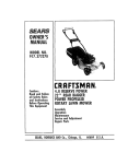
I:RRFrSMRN®
MANUAL
MODELNO.
917.372451
5.0 HORSE
POWER
22" REARBAGGER
POWERPROPELLED
ROTARYLAWNMOWER
Each Lawn Mower has its own model number. Each
engine has its own model number°
The model number for your lawn mower witl be found on
a decal attached to the rear of the lawn mower housing,.
The model number for the engine will be found on the
Blower Housing of the engine adjacent to the spark plugo
All parts listed herein may be ordered through Sears,
Roebuckand Co. Service Centers and most Retail Stores°
WHENORDERING
REPAIR
PARTS,ALWAYS
GIVETHEFOLLOWING
INFORMATION:
* PRODUCT
- "ROTARYLAWNMOWER"
HOWTO ORDER
REPAIR
PARTS
* MODELNUMBER- 917_372451
* ENGINE
- BRIGGS/STRATTON
MODELNO, 124702 TYPENO. 3121-01
" PARTNUMBER
* PARTDESCRIPTION
Your Sears merchandise has added value when you consider that Sears has service units nationwide staffed with
Sears trained technlcians.°.professional technicians
specifically trained on Sears products, having the parts,
tools and the equipment to insure that we meet our pledge
to you, we service what we sell,
i
75t901 Rew 2 06/04/90
Printedin U.S.A.