1
OWNER'S
MANUAL
MODEL NO.
580.327060
CRRFTSMRNo
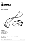
120-240 VOLT/4000 WATT A-C
PORTABLE A-C GENERATOR
CAUTION:
with Automatic Idle Control
Read and Follow
all Safety Rules
and Instructions
Assembly
Before Operating
Operation
This Equipment
Maintenance
Service and Adjustment
Repair Parts
SEARS
ROEBUCK
AND
Co.,
Chicago,
IL
60684
U.S.A.
o
36
6
PartNo. 80059GS_v3-1./11/90
SAFETY RULES
&
CAUTION:
CONTACT
ALWAYS
SPARK
DISCONNECT
PLUG,
TO PREVENT
SPARK PLUG
ACCIDENTAL
WIRE AND STARTING
PLACE WtREWHEN
WHERESETTING
IT CANNOT
UP,
TRANSPORTING,
ADJUSTING OR MAKING REPAIRS TO YOUR GENERATOR.
A
IMPORTANT
THIS GENERATOR IS DESIGNED FOR OUTDOOR USE ONLY. USING THIS GENERATOR
INSIDE ANY
BUILDING OR ENCLOSURE, INCLUDING THE GENERATOR COMPARTMENT OF A RECREATIONAL VEHICLE
(RV), IS DANGEROUS. FIRE OR AN EXPLOSION MAY RESULT. NO USER PERFORMED MODIFICATIONS,
INCLUDING VENTING OF EXHAUST ANDIOR COOLING VENTILATION, WILL ELIMINATE THE DANGER.
If this unit is used for backup power inthe event of a
utitity power failure, take the following steps: BEFORE
CONNECTING
THE GENERATOR TO AN ELECTRICAL SYSTEM OPEN THE MAIN CIRCUIT BREAKER
OR MAIN SWITCH SERVING THE SYSTEM TO ISOLATE THE GENERATOR
SYSTEM
FROM THE
ELECTRIC
UTILITY.
FAILURE TO ISOLATE THE
GENERATOR
AND UTILITY
SYSTEMS
MAY
RESULT IN DAMAGE TO THE GENERATOR AND
MAY ALSO RESULT IN INJURY OR DEATH TO
ELECTRIC
UTILITY WORKERS
DUE TO BACKFEED OF ELECTRICAL ENERGY.
This generator supplies dangerously high electrica!
voltages.
Use care to prevent extremely hazardous
and possibly lethal electrical shock. Never permit any
unqualified person(s) to operate or service the unit.
DO NOT operate this equipment in the rain, while
standing in water, while barefoot, or white hands or
feet are wet. Dangerous electrical shock will result.
Maintain all wiring, extension cords, etc., in good
condition. Worn, bare, frayed, or otherwise damaged
wiring and cord sets may cause dangerous electrical
shock and may also result in damage to equipment
and!or property.
The National Electrical Code requires that the generator be properly connected to an approved earth
ground.
Local electrical codes may also require
proper grounding of the unit. See ASSEMBLY section
for more grounding information.
Wire gauge sizes of wiring and cord sets must be large
enough to handle the maximum electrical load to
which they will be subjected. Cord sets must be rated
125 a-c volts at 20 amperes or (or greater).
Some
electrical devices, however, do not require that cord
rating. Refer to the Owner's manual of the electrciat
device for the manufacturer's
recommendations.
The generator engine consumes oxygen and gives off
DEADLY carbon monoxide gas through its exhaust
system. This dangerous gas, if breathed in sufficient
concentrations, can cause unconsciousness or even
death. Operate this equipment outdoors only, in well
ventilated areas where exhaust gases cannot accumulate and endanger people or animals.
,_
°
•
•
•
•
Gasoline is extremely FLAMMABLE
and its vapors are
EXPLOSIVE.
Comply with all laws regulating the
storage and handling of gasoline.
DO NOT permit
smoking, open flames, sparks or heat in the vicinity
while handling gasoline.
Avoid spilling gasoJine on a
hot engine.
DO NOT fill fuel tank while engine is
running or hot. Clean off any spilled gasoline before
starting engine.
DO NOT fill fuel tank completely
full. Allow room at
top of tank for fue! expansion or fuel may expand and
over/low onto a hot engine.
Drain all gasoline from tank before transporting your
generator inside your car or other vehicle.
DO NOT store the generator with fuel in tank where
gasoline vapors might reach an open flame, spark, or
pilot light, as on a furnace, water heater, dryer, etc.
FIRE or an EXPLOSION
might result.
DO NOT insert any object or tool through cooling air
slots or openings of the engine or generator, even if
the engine is not running.
Damage to the unit or
personal injury may result.
•
DO NOT attempt to change the engine governed
speed. Factory settings are correct when you receive
the unit. Excessively high engine speeds may result
in injury or damage to equipment.
"
DO NOT use the unit if it has been damaged. Repair
or replace all damaged
or defective
components
before you run the unit.
DO NOT permit children to operate or service the
generator.
•
Read your Owner's Manual carefully.
Only persons
who are familiar with these safety rules and have been
properly instructed in the use of this product should be
permitted to use the product.
SAFETY
PRECAUTIONS.
IT MEANS
"ATTENTION!!I.
LOOK FOR
THIS SYMBOL TO
POINT OUT
IMPORTANT
BECOME ALERT!H
YOUR SAFETY IS INVOLVED."
CONGRATULATIONS
on your purchase of a Sears
Craftsman Generator. tt has been designed, engineered
and manufactured to give you the best possible dependability and performance.
Shoul_you experience any problem you cannot
remedy, please contact your nearest Sears Service
ter/Department. We have competent, well-trained
nicians and the proper tools to service or repair this
easily
Centechunit.
Please read and retain this manual. The instructions will
enable you-to assemble and maintain your generator
prepedy. Always observe the 'SAFETY RULES."
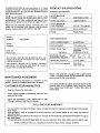
MODEL
NUMBER
PRODUCT
Generator
SPECIFICATIONS
Specifications
RATED MAXIMUM
POWER
4000 Watts (2.4 kW)
RATED VOLTAGE
120/240 Volts a-c
RATED MAXIMUM
LOAD CURRENT
33.3/16.7 a-c amperes
RATED FREQUENCY
60 Hz at 3600 rpm
PHASE
Single Phase
Engine Specifications
580.327060
RATED HORSEPOWER
8 at 3600 rpm
DISPLACEMENT
19.3 cubic inches
SPARK PLUG: Type:
Champion RJ171M or
equivalent
0.030 inch (0.76mm)
SERIAL
NUMBER
DATE OF
_
PURCHASE
MAXIMUM (full tank)
OPERATING TIME (hrs)
THE MODEL AND SERIAL NUMBERS
WILL BE
FOUND ON A DECAL AI-I-ACHED TO THE GENERATOR STATOR CAN.
YOU SHOULD RECORD BOTH SERIAL NUMBER
AND DATE OF PURCHASE AND KEEP IN A SAFE
PLACE FOR FUTURE REFERENCE.
MAINTENANCE
AGREEMENT
RESPONSIBILITIES
•
Read and observe the safety rules.
•
Follow regular schedule in maintaining,
using your generator.
full load
1,0
3/4
1.25
1/2
t.5
GASOL1NE CAPACITY
1.0 U.S. gallon
OIL (1.5 U.S. pint capacity)
SAE 30 Oil
(SAE 10W-30)
1t4
t.5
NOTE: This generator is equipped with a spark arrestor
muffler. The spark arrestor must be maintained in effective
working order by the owner/operator.
A Sears Maintenance Agreement is available on this
product. Contact your nearest Sears store for details.
CUSTOMER
Set Gap to:
In the State of California a spark arrestor is required by law
(Section 4442 of the California Public Resources Code).
Other states have similar laws. Federal laws apply on
federal lands.
caring for and.
Follow the instructions under "Maintenance"
"Storage" sections of this Owner's Manual.
FULL
and
ONE YEAR
WARRANTY
For one year from the date of purchase, Sears will repair any defect in material or workmanship in this generator
at no charge.
If the generator is used for commercial or rental purposes, this warranty applies for only ninety days from the
date of purchase.
Warranty service is available by returning to the nearest SEARS SERVICE CENTER/DEPARTMENT throughout
the United States.
This warranty gives you specific legal rights and you may also have other rights, which va,'y from state to state.
SEARS, ROEBUCK AND CO., Department
731CR-W, Sears Tower, Chicago, IL 60684
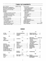
TABLE OF CONTENTS
SAFETY RULES .............................. INSIDE COVER
MAINTENANCE AGREEMENT ............................... 1
MAINTENANCE
General Recommendations ................................. 8
Generator Maintenance ....................................... 8
CUSTOMER RESPONSIBILITIES ...........................
PRODUCT SPECIFICATIONS ................................
1
1
WARRANTY .............................................................
ASSEMBLY
1
Engine Maintenance ............................................
SERVICE AND ADJUSTMENTS
To Remove Generator from Carton ...................... 3
Engine Speed ......................................................
Carburetor ............................................................
10
t0
Check Compression .............................................
Check Ignition ......................................................
Check Carburetion ...............................................
I0
11
t1
8-9
Paris Shipped Loose with Unit .............................
3
Cord Sets and Connector Plugs ...........................
Grounding the Generator .....................................
OPERATION
3
3
Know Your Generator ...........................................
4
Before Starting Engine .........................................
5
To Start Engine ....................................................
Connecting Electrical Loads .................................
5
6
Storage Instructions .............................................. 11
TROUBLESHOOTING POINTS .............................. 12
WIRING DIAGRAM .................................................. 14
Stopping the Engine .............................................
Don't Overload the Generator ..............................
6
7
REPAIR PARTS ....................................................... 15-23
PARTS ORDERING .............................
BACK COVER
Wattage Reference Guide ....................................
7
STORAGE
General ................................................................
11
INDEX
-A-
-G-
-R-
Air Filter .................
8
Generator Maintenance .....
8
Assembly
3
Grounding ................
Gasoline .................
3
5
................
-BBattery
Charging ...................
Safety .....................
Before Starting ............
6
6
5
Lubrication
...............
5, 8
-MMaintenance
Carburetor ................
Check Carburetion .........
11
12
Check Compression ........
Check lgnitition ............
Circuit Breaker ............
11
11
7
Connecting Electrical Load... 6
Cord Sets, 120 volts ........
3
Customer Responsibilities
... 1
Agreement ..................
Engine .....................
Generator ..................
Recommendations ...........
1
8
8
8
Spark Arrestor ...............
9
Spark Plug ..................
9
-OOperation ................
Overloads ................
-E-
Oil Level
...................
Speed .....................
8
5
Safety Rules ...........
inside cover
Service and Adjustments
Carburetor ..................
11
Carbutetion .................
12
Checking Compression........
12
Checking Ignition .............
11
Engine Speed ...............
11
Service Recommendations .. 10
Specifications .............
Starting Engine ............
Stopping Engine ...........
Storage ..................
1
5
6
12
-T4-7
7
=p=
................
8
9
-S-L-
-C-
Engine
Maintenance
Replace Foam Filter ........
Replace Paper Element .....
Troubleshooting ...........
13
-W-
Parts, loose in carton .......
Parts, repair ..............
11
2
3
15-23
Warranty .................
1
Wattage Reference Guide ... 7
Wiring Diagram ............
14
ASSEMBLY
Your a-c generator was completely assembled at the factory. It is ready for use after it has been properly serviced
with the recommended lubricating oil and fuel.
IMPORTANT:
ANY A]-I-EMPT TO RUN THE ENGINE
BEFORE IT HAS BEEN SERVICED WITH THE RECOMMENDED OIL WILL RESULT IN AN ENGINE FAILURE.
TO REMOVE
•
GENERATOR
FROM
CARTON
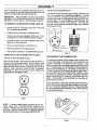
120/240 VOLTS RECEPTACLE:
A 240 volts, 20 amp, twistlock type mating connector plug
(Fig. 2) is required when using this receptacle. A 4-wire
cord set, rate 20 a-c amperes at 250 volts (or greater), is
required and must be connected to the plug and to the
desired load(s). To order additional connector plugs, see
REPAIR PARTS section of this manual.
You may also
purchase plugs at a local electrical supply store, ordering
NEMA type L14-20P.
Set the carton on a flat rigid surface with "THIS SIDE
UP" arrows pointing upward.
•
Carefully open the top flaps of shipping carton.
•
Remove any loose parts shipped with the unit. These
are shipped in a brown manilla or plastic envelope.
°
Cut down comers at one end of shipping carton and lay
that side of carton down flat.
4-Wtre Cord Se!
Remove packing material, carton tillers, etc.
N E tvIA
Remove generator from shipping carton.
O AMP
L14-2 OH
Check carton carefully for any additional loose parts.
FIG. 2
CORD
SETS
AND
CONNECTOR
PLUGS
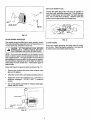
GROUNDING
THE GENERATOR.
120 VOLTS DUPLEX RECEPTACLE
Use only high quality, well-insulated, 3-wire grounded extension cords with the generator's 120-volt "duplex" type
electrical receptacles (Fig. t ). All cord sets used should be
rated 125 volts at 20 a-c amps or greater for most electrical
devices. Keep extension cords as short as possible,
preferably less than t 5 feet long to prevent voltage drop
and possible overheating of wires.
@
.@
The National Electrical Code requires that the frame and
external electrically conductive parts of this generator be
properly connected to an approved earth ground. Local
electrical codes may also require proper grounding of the
unit. For that purpose, a GROUNDING LUG is provided on
the base of the cradle (Fig. 3). Generally, connecting a No.
t 2 AWG (American Wire Gauge) stranded copper wire to
the grounding lug and to an earth-driven copper or brass
grounding rod (electrode) provides adequate protection
against electrical shock. However, local codes may vary
widely. Consult with a local electrician for grounding requirements in your area.
Proper grounding of generator will help prevent electrical
shock in the event of a ground fault condition in the generator or in connected electrical devices. Proper grounding
also helps dissipate static electricity, which often builds up
in ungrounded devices.
120 V. A.C.
]FIG. !
NOTE: To obtain suitable mating 120 volts, 20 amp connector plugs, refer to REPAIR PARTS section of this
manual. Suitable connector plugs may also be purchased
at a local electrical supply store by specifying National
Electrical Manufacturer's Association (NEMA) 5-20P.
]FIG. 3
3
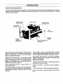
OPERATION
KNOW YOUR GENERATOR
READ THIS OWNER'S MANUAL AND SAFETY RULES BEFORE OPERATING YOUR GENERATOR. Compare the
illustrationswith your generator, to familiarize yourseff with the locations of various controls and adjustments. Save this
manual for future reference.
120/240 VO LTS
RECEPTACLE
FUEL TANK
SPARK PLUG
i STOP SWITCH
120 VOLTS
RECEPTACLES
.t
AIR
CLEANER
SPARK ARRESTOR
MUFFLER
AIR CLEANER - Uses a dry type filter element to limit the
amount of dirt and dust that gets in the engine. Some units
may be equipped with an optional, dry type pre-cleaner.
120 VOLTS "DUPLEX" RECEPTACLES - May be used to
supply electrical power for the operation of 120 volts at 20
amps a-c, single phase, 60 Hz, a-c electrical lighting,
applicance, tool and motor loads.
FUEL TANK- Can hold one (1) U.S. gallon of gasoline.
Unleaded gasoline is recommended, but regular leaded
gasoline is acceptable.
amount of fuel in tank.
120/240 VOLTS RECEPTACLE - May be used to supply
electrical power for the operation of up to 240 volts at 20
amps a-c, single phase, 60 Hz, a-c electrical lighting,
applicance, tool and motor loads. Twistlock connectors are
required when using this receptacle.
SPARK PLUG STOP SWITCH - Contact this switch with
spark plug to shut down engine.
SPARK ARRESTOR MUFFLER - Exhaust muffler has a
spark arrestor screen.
RECOIL STARTER
engine.
IDLE CONTROL SWITCH (not shown) - Provides automatic control of governed speed, which only runs at high speed
when loads are connected. Otherwise it runs at a slower
idle speed.
- (Not shown) Used for starting the
CHOKE (not shown) - Used when starting a cold engine.
OIL FILL (not shown) - Check and maintain correct oit level
here.
4
OPERATION
BEFORE
STARTING
ENGINE
ADD OIL:
•
Place generator on a level surface and remove oil fill
plug (Fig. 4). Fill with Sears SAE 30 detergent oil to
point indicated on oil dipstick. SAE 10W-30 oil may
also beused. DO NOTUSESAE 10W-40OIL. POUR
SLOWLY. Oil capacity of engine is 1.5 U.S. pints.
When oil pan is full, install and tighten oil fill plug.
ADD GASOLINE:
Fill fuel tank with clean, fresh, UNLEADED gasoline.
Leaded REGULAR grade gasoline may also be used.
DO NOT USE PREMIUM GASOLINE. BE CAREFUL
NOT TO OVERFILL FUEL TANK.
FIG. 4
FULt CHOKE POSITION
_,
WARNING:
Experience indicates that alcohol-blended
fuels (called gasohol or using ethanol or methanol) can
attract moisture which leads to separation and formation of
acids during storage. Acidic gas can damage the fuel
system of an engine while in storage. To avoid engine
problems when using gasohol, the fuel system should be
emptied before storage periods of 30 days or longer. Drain
the gas tank, start the engine and let itrun until the fuel lines
and carburetor are empty. Use fresh fuel next season. See
STORAGE INSTRUCTIONS for additional information.
Never use engine or carburetorcleaner products in the fuel
tank or permanent damage may occur.
,,'_"_.
j-"_===CHOKE LEVER
=_
_%= _'_// NO Cf(C'KE
POSITION
]FIG, 5
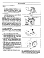
TO START THE ENGINE
Unplug all electrical loads from generator receptacles
before starting the engine. Never start or stop the engine
with electrical devices plugged into panel receptacles and
turned on.
Start, store and fuel the unit in a level position.
Apply the choke (Fig. 5). Rotate choke lever to its FULL
CHOKE POSITION. If engine is warm, close the choke
only part way or leave it fully open. A warm engine
needs less choking than a cold engine.
][_[G. 6
Check that the spark plug wire is connected to engine
spark plug. Also check that the Stop Switch next to
spark plug (if so equipped) is not contacting the spark
plug (Fig 6).
Crank engine. Grasp the starter grip (Fig. 7) and pull
slowly until you feel some resistance. Let rope return
slowly. Then pull cord out with rapid full arm stroke. Let
rope return slowly. Do not let rope "snap back" against
starter. Repeat until engine starts.
When engine starts, move the choke to "1/2 CHOKE"
until engine runs smoothly, then to "NO CHOKE" position as engine Warms up.
FiG. 7
Let the engine stabilize and warm up for a few minutes.
Then plug in and turn on the desired electrical loads.
NOTE: If engine "hunts" or falters after starting, apply the
choke until the engine begins running smoothly. If engine
continues to hunt, you may need to adjust the carburetor.
See SERVICE AND ADJUSTMENTS on Page 10.
5
OPERATION
CONNECTING
•
ELECTRICAL
LOADS
Use this generator to operate 120_240 volts, single
phase, 60 Hz, a-c lighting, appliance, tool and motor
loads.
DO NOT connect 240 volts to the 120 volts duplex
receptacles.
DO NOT connect any 3-phase loads to panel receptacles.
ZDLE
CONTROL
SYSTEM
DO NOT connect any 50 Hz loads to the generator.
Add up the rated watts of all lights, tool, appliance and
motor loads you are powering at one time. This total
should NOT be greater than (a) the generator's rated
wattage capacity, or (b) the circuit breaker rating of the
receptacle supplying power. See "Don't Ovedoad the
Generator" on Page 7.
STOPPING
HG. 8
THE ENGINE
Unplug all electrical loads from the generator panel
receptacles. Never start or stop the engine with electrical devices plugged in and turned on.
The Idle Control System may be briefly described as fol-
Let the engine run at no-load for several minutes to
stabilize the internal temperatures of engine and generator.
Power voltage for Electromagnet operation is available
to the Idle Control Circuit Board, via Wires 11D and 22.
Push Stop Switch (Fig. 7) against spark plug and hold
until engine has come to complete stop.
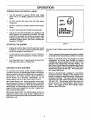
AUTOMATIC
IDLE CONTROL
An Automatic Idle Control system provides greatly improved luel economy by operating the unit at its normal high
governed speed only when electrical loads are plugged in
and turned on. The system consists of (a) an Idle Control
Circuit Board, (b) a Sensing Transformer,
(c) an
Electromagnet, and (d) an Idle Control Switch (Fig. 8).
Idle Control Switch ON: Engine-generator runs at high
governed speed only when an electrical toad is connected
to the generator and turned on. When the electrical load is
disconnected, an Electromagnet is energized to pull the
engine throttle control against its idle stop. Engine then
runs at reduced (idle) speed.
Idle Control Switch OFF: The Electromagnet cannot be
energized, since its power circuit is open. Engine runs at
high governed speed (about 3600 rpm) whether load (s) are
connected or not.
tows:
When an electrical load is not plugged in to panel
receptacles, no current flows through the Sensing
Transformer primary winding and no current flow is
present in the Transformer secondary winding. The
Idle Control Circuit Board then completes the circuitto
the Electromagnet, which energizes to pull the engine
throttle back against its idle stop. The .engine-generator runs at idle speed.
When an electrical load is plugged in, current flows
through the primary windings of the Sensing Transformer, to induce a current flow into the Transformer's
secondary windings..This
current flow to the load is
"sensed" by the Idle Control Circuit Board, via Wires
155 and 156. Circuit board action then opens the
power circuit to the Electromagnet, which de-energizes. The engine governor then maintains engine
speed at about 3600 rpm.
OPERATION
DON'T OVERLOAD
THE GENERATOR
This generator is equipped with 20-amp circuit breakers,
which protect the unit against electrical overload. Overloading a generator in excess of its rated wattage capacity
can result in damage to the generator to connected electrical devices. Observe the following, to prevent overloading
the unit.
Add up the total wattage of all electrical devices to be
connected at one time. This total should NOT be
greater than the generator's wattage capacity.
The rated wattage of lights can be taken from light
bulbs. The rated wattage of tools, appliances and
motors can usually be found on a data plate or decal
affixed to the device.
Some electric motors,such as induction types, require
about two and a halt times more watts of power for
starting than for running. This surge of power lasts only
a few seconds when starting such motors. Make sure
you allow for this high starting wattage when selecting
electrical devies to connect to your generator. First,
figure the watts needed to start the largest motor. Add
to that figure the running watts of all other connected
loads.
The GUIDE below is provided to assist you in determining how many items your generator can operate at
one time.
If the appliance, tool or motor does not give wattage,
mulitply 120 volts times ampere rating to determine
watts (volts x amps = watts).
WATTAGE
REFERENCE
GUIDE
RUNNING
RUNNING
WATTS
WATTS
*Air Conditioner (12,000 Btu) ................................... 1700
Lawn Mower .............................................................
1200
Battery Charger (20 amp) .........................................
Belt Sander (3") ........................................................
Chain Saw ................................................................
500
1000
t200
Ught Bulb ..................................................................
Microwave Oven .......................................................
*Milk Cooler ...................... _.......................................
100
700
1100
Circular Saw (6-12/") ...................................... 800 to 1000
Coffee Maker ............................................................
1000
Oil Burner on Furnace ..............................................
300
Oil Fired Space Heater (140,000 Btu) ......................
Oil Fired Space Heater (85,000 Btu) ........................
400
225
*Compressor
*Compressor
(1 HP) .................................................
(3/4 HP) ..............................................
2000
1800
*Compressor
(1/2 HP) ..............................................
1400
Curling Iron ................................................................
*Deep Freeze ............................................................
Disc Sander (9") .......................................................
700
500
1200
Edge Trimmer ............................................................
Electric Nail Gun ......................................................
500
1200
Oil Fired Space Heater (30,000 Btu) ........................
150
*Paint Sprayer, Airless (1/3 HP) ...............................
600
Paint Sprayer, Airless (handheld) ............................
150
Radio .................................................................
50 to 200
*Refrigerator ..............................................................
Slow Cooker..............................................................
600
200
*Submersible Pump (1-1/2 HP) ................................
2800
Electric Range (one element) ................................... 1500
Electric Skillet ............................. .............................. 1250
*Submersible Pump (1 HP) ......................................
*Submersible Pump (1/2 HP) ...................................
2000
1500
*Furnace Fan (1/3 HP) .............................................
Sump Pump ..............................................................
600
*Table Saw (10")......................................... 1750 to 2000
Television ......................................................... 200 to 500
Weed Trimmer ..........................................................
500
1200
Hair Dryer .................................................................
1200
Hand Drill (1") ...........................................................
1100
Hand Drill (1/2") .............................................
750 to 1000
Hand Drill (3/8") .........................................................
500
Hand Drill (1/4") .........................................................
250
Hedge Trimmer .........................................................
Impact Wrench ..........................................................
450
500
*Jet Pump ..................................................................
800
* Allow 2-1/2 times the listed watts for starting these
devices.
MAINTENANCE
GENERAL
RECOMMENDATIONS
ENGINE MAINTENANCE
CHECKING OIL LEVEL
The Owner/Operator is responsible for making sure that all
periodic maintenance tasks are completed on a timely
basis; that all discrepancies are corrected; and that the unit
is kept clean and properly stored.
Never operate a
damaged or defective generator. Follow the recommendations in the SERVICE RECOMMENDATIONS chart on
page 12.
Oil level should be checked prior to each use or at least
every five hours of operation. See OPERATION section
for more information.
CHANGING OIL
Change oil after first five hours of operation. Change oil
every 50 hours thereafter. If you are using your generator
under dirty or dusty conditions, or in extremely hot weather,
change oil every 25 hours of operation.
CAUTION:
DISCONNECT
SPARK PLUG WIRE
FROM SPARK PLUG AND PLACE WIRE WHERE IT
CANNOT COME IN CONTACT WiTH YOUR SPARK
PLUG BEFORE WORKING ON YOUR GENERATOR.
GENERATOR
Change oil while engine is still warm from
follows:
MAINTENANCE
Generator maintenance constists of keeping the unit clean
and dry. Operate and store the unit in a clean dry environment where it will not be exposed to excessive dust, dirt,
moisture or any corrosive vapors. Cooling air slots in the
generator must not become clogged with snow, leaves,or
any other foreign material.
running, as
•
Remoye oildrain plug (Fig. 9) anddrain
into a suitable container.
oil completely
•
When all oil has drained, install and tighten oil dry,in
plug.
Check the cleanliness ofthe generator frequently and clean
when dust, dirt, oil, moisture or other foreign substances
are visible on its exterior surface.
Cooling Fin
NOTE: We DO NOT recommend using a garden hose to
clean generator. Water can enter the engine fuel system
and cause problems. In addition, if water enters the generator through cooling air slots, some of the water will be
retained in voids and cracks of the rotor and stator winding
insulation. Water and dirt buildup on the generator internal
windings wilt eventually decrease the insulation resistance
of these windings.
o,,
and Dipstick
Use a damp cloth to wipe exterior surfaces clean.
"
A soft, bristle brush may be used to loosen caked on
dirt, oil, etc.
•
A vacuum cleaner may be used to pick up loose dirt
and debris.
__
Drain Plugi
FIG. 9
•
TO CLEAN THE GENERATOR:
•
F
Remove oil filler plug/dipstick. Fill engine to point
indicated on oil dipstick. DO NOT fill above "FULL"
mark. You will need about 1.5 pints.
°
When engine sump pump isfilled to proper point, install
and tighten oil tiller plug/dipstick.
SERVICE AIR CLEANER
Your engine will not run properly and may be damaged if
you run it using a dirty air cleaner.
Low pressure air (not to exceed 25 psi) may be used
to-blow away dirt. Inspect cooling air slots and openings on the generator. These openings must be kept
clean and unobstructed.
Replace paper air cleaner element: If engine is equipped
with paper type cleaner (Fig. 10) clean or replace air filter
at least once each year. Replace more often if operating
under extremely dirty or dusty conditions DO NOT ATTEMPT TO CLEAN OR OIL THE PAPER FILTER. Install
a new paper filter as follows.
CAUTION: NEVER INSERTANY OBJECT ORTOOL
THROUGH THE AIR COOLING SLOTS, EVEN IF
THE ENGINE IS NOT RUNNING. DAMAGE TOTHE
UNIT OR PERSONAL INJURY MAY RESULT.
8
•
Remove WING NUT, COVER and PAPER
Discard the PAPER FILTER.
FILTER.
•
Clean inside of BASE and COVER thoroughly.
•
Position new PAPER FILTER on BASE.
•
Install COVER and secure it to BASE with WING NUT.
REPLACE SPARK PLUG
Change the spark plug every 100 hours of operation or
once each year, whichever comes first. This will help your
engine to start easier and run better. Set spark plug gap
(Fig. 12) to 0.030 inch (0.76mm). Remove spark plug
access cover to gain access to the spark plug.
COW:-
BASE
t
PAPERFILTER
.030" (#6 rnrn) _,_
FEELER GAUGE t
WINGNU"
SPARK
PLUG
FIG. 10
CLEAN SPARK ARRESTOR
FIG. 12
The engine exhaustmuffler has a spark arrestor screen.
The screen should be inspected every 100 operating hours
or once each year, whichever comes first.
_k
CLEAN ENGINE
CAUTION: LET THE MUFFLER COOL BEFORE i
WORKING ON IT. CONTACT WITH A HOT MUFFLER ORENGINE CAN CAUSESEVERE BURNS.
I
NOTE: If you use your generator on any forest-covered,
brush-covered or grass-covered unimproved land, it must
have a spark arrestor. The spark arrestor must be cleaned
and maintained in good condition by the owner or operator.
The preceding is required by law in the State of California.
Other states my have similar laws. Federal laws apply on
federal lands.
Clean and inspect the spark arrestor as follows (Fig. 11 )
•
Remove four screws, then remove the exhaust outlet
pipe and its gasket.
•
Clean the screen with a commercial cleaning solvent.
•
Inspect the screen and replace if torn, performed or
otherwise damaged.
DO NOT USE
a defective
screen.
•
Use a new gasket and install the exhaust outtet pipe.
Retain with four screws.
EXHAUST
PIPE
OUTLET
SCREEN
SCREWS
(4)
FIG. 11
9
Inspect the engine frequently and clean when its cooling
fins are dirty. Clean the engine cooling fins. Also clean the
air intake screen around the starter housing.
SERVICE
RECOMMENDATIONS
Periodic Maintenance
P ERIODI(_"MAINTENANCE
Maintenance Task
After First
2 Hours
EverY
5 Hours
1, Check engine oil level
2. Change engine oil*
Every
20 Hours
Chart
INTERVAL
Every
25 Hours
Once
Annually
X
X
X
3. Replace paper filter
type air cleaner**
X
4. Clean & re-oil foam type
air cleaner (if so equipped)
X
5. Check engine spark plug
X
6. Inspect spark arrestor
7, Inspect engine-generato_
8 Prepare unil for storage
Other
X
X
X
I
....... I
]0
t
X
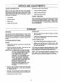
SERVICE AND ADJUSTMENTS
ENGINE
SPEED
Rotate the THROTTLE counterclockwise and hold it
against the THRO-I-FLE STOP. While holding it in this
position, turn IDLE VALVE in slowly and then out
slowly. Set at midpoint between rich and lean.
Engine speed was properly adjusted at the factory and
should require no additional adjustment. Do not attempt to
change engine speed. If you believe the engine is running
too fast or too slow, take your generator to. an authorized
Sears Service Center for repair and adjustment.
Release THROTTLE.
If engine does not accelerate
properly, readjust carburetor to a richer mixture.
Your generator engine runs at a constant speed. This
constant operating speed is maintained by a mechanical,
flyweight type, fixed speed govenor. DO NOT try to adjust
the governed speed setting for the following reasons:
IOLE AIR
BLEED
High engine speeds are dangerous and increase the
risk of personal injury or damage to equipment.
MAIN AIR
BLEED
Low engine speeds impose a heavy load on the engine
when sufficient engine power is not available and may
shorten engine life.
SHUTTER
The generator will supply correct rated a-c frequency
and voltage only at the proper speed. Some connected
electrical devices could be damaged by incorrect frequency and/or voltage.
CARBURETOR
The engine carburetor was factory adjusted and, under
most normal conditions, should require no additional adjustment. However, some minor adjustment may be required to compensate for differences in fuel, temperature,
altitude, or load on the engine.
NOTE: DO NOT remove the air cleaner when running
engine. Operation without fully assembled air filter installed may cause engine damage.
INITIAL CARBURETOR
INLET NEEDLE
AND SEAT
IDLE
ADJUSTMENT
Gently turn IDLE VALVE and NEEDLE vALVE (Fig.
14) clockwise until they just close. Valves may be
damaged by turning them in too far.
•
Open NEEDLE VALVE
counterclockwise.
•
Open IDLE VALVE one turn counterclockwise.
one and a half
FINAL ADJUSTMENT:
Start engine and let it warm up at least five minutes.
•
Turn NEEDLE VALVE in (clockwise-lean
engine starts to slow down.
•
Turn NEEDLE VALVE out (counterclockwise
mixture) past the smooth operating point.
°
Turn the needle valve in (lean mixture) to midpoint
between rich and lean.
AJUSTMENT
FIG. 14
Remove spark plug and hold thumb over spark plug hole
while cranking engine. Compression should be sufficient
to push thumb off the opening. If compression appears low,
check for the following:
turns
•
_MAIN
CHECK COMPRESSION
ADJUSTMENT:
=
FLOAT
MA_N NOZZLE
mixture) until
- rich
]]
•
Loose cylinder head bolts.
•
Blown head gasket
•
Worn or damaged
Department.
engine.
Contact Sears Service
SERVICE AND ADJUSTMENTS
CHECK
if plug is dry, look for the following:
CARBURETION
Make sure gas tank is filled with clean, fresh gasoline.
Make sure fuel shutoff valve is open. Make sure fuel flows
freely through fuel line between tank and carburetor. Crank
engine several times, then remove spark plug. If plug is
wet, look for the following:
•
Leaking carburetor gaskets
•
Gummy or dirty carburetor
•
Intake valve stuck closed
CHECK
•
Overchoking
•
Rich fuel mixture
•
Water in fuel
•
Intake Valve stuck open
IGNITION
Remove spark plug wire from plug and hold metal terminal
end of wire near engine metal part. Crank engine. A spark
should jump the gap from wire to engine. If spark occurs,
try a new spark plug. If no spark occurs, contact Sears
Service Department.
STORAGE
GENERATOR:
GENERAL
The generator should be started at least once every seven
days and allowed to run at least 30 minutes. If this cannot
be done and you must store the unit for more than 30 days,
use the following information as a guide to prepare it for
storage.
STORAGE
While engine is stillwarm, drain oil from crankcase and
refill with fresh oil.
•
Remove all fuel from fuel tank. Drain tank and run
engine until it stops from lack of fuel.
IMPORTANT: 1T IS IMPORTANT TO PREVENT GUM
DEPOSITS FROM FORMING tN ESSENTIAL FUEL SYSTEM PARTS SUCH AS
THE CARBURETOR, FUEL FILTER,
FUEL HOSE, OR TANK DURING
STORAGE. ALSO, EXPERIENCE INDICATES THAT ALCOHOL BLENDED
FUELS (called gasohol or using ethanol
or methanol) CAN AI-rRACT MOISTURE
WHICH CAN FORM ACIDS THAT
SEPARATE DURING STORAGE.
ACIDIC GAS CAN DAMAGE THE FUEL
SYSTEM OF AN ENGINE WHILE IN
STORAGE.
as outline on Page 8 ("Cleaning
•
Check that cooling air slots and openings on generator
are open and unobstructed.
TIPS:
•
Do not store gasoline from one season to another.
•
Replace your gasoline can if tt starts to rust. Rust
and!or dirt in your gasoline can cause problems when
you use it with this unit.
Do not store the generator under any plastic cover. Plastic
cannot breathe, allowing condensation (moisture) to form.
This condensation can cause your generator to rust.
NOTE: If you must store the generator with fuel in the fuel
tank, using a fuel additive such as STA-BIL®, or an
equivalent will prevent fuel gum deposits from forming.
Remove spark plug and pour about 0.5 ounce (15cc)
of engine oil into cylinder. Crank engine to distribute
oil. Install spark plug.
Clean dirt, oil, and grease from cylinder, cylinder head,
fins, blower housing, rotating screen and muffler area.
•
Clean the generator
the Generator").
OTHER STORAGE
INSTR UCTIONS
ENGINE:
•
•
Store generator in dean, dry area.
]2
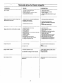
TROUBLESHOOTING
PROBLEM
No a-c output.
Engineruns goodat no-loadbut "bogs down"
whenloads are con-ected.
CAUSE
CORRECTION
1.20 amp circuit breaker open.
2. Fault in generator.
3. Poor connection or defective cord set.
4. Connected device is bad.
1. Reset circuit breaker.
1. Short circuit in a connected electrical load.
2. Engine speed too slow.
3. Generator is overloaded.
4. Shorted
Engine will not start or starts and runs rough.
Engine lacks power
Engtne 'hunsts" or falters.
Other engine problems
POINTS
generator circuit,
2, Contact Sears Service Dept,
3. Check and repair,
4. Connect another device that is in good
conditon.
f. Disconnect shorted electrical load.
2. Contact Sears Service Dept.
3. See "Don't Overload the Generator on
Page 7.
4, Contact Sears Service Dept.
1. Run/Stop Switch set to Stop.
2, Dirty air cleaner
3. Out of gasoline.
1. Set switch to RUN,
4. Stale gasoline.
5. Spark plug wire not connected to spark plug.
6. Bad spark plug.
7. Water in gasoline.
8.0verchoking.
9. Excessively rich fuel mixture.
10. Intake valve stuck open orclosed.
1 I. Engine Compression lost.
4. Drain gas tank; fill with fresh gasoline.
5, Connect wire to spark plug.
6. Replace spark piug,
7. Drain gas tank; fill with fresh gasoline.
8. Open choke fully E[ndcrank engine
9. Adjust carburetor (see Page 11)
10. Contact Sears Service Deptartment
11. Contact Sears Service Department.
1, Load is too high.
1. See "Don't Overload the Generator on
2. Dirty air filter.
Page 7
2.Replaco air filter..
1. Choke is openedtoosoon.
2. Clean or replace air cleaner,
3. Fill fuel tank.
2. Carburetoris running toorichor toolean.
1. Move choke to ha_way position until engine runs smoothly.
2. Adjust carburetor.
Check compression, ignition, carburetion, or a-c
generation.
See informationin "Service and Adjustmenmts"
on Page 10.
]3
::0
}>
"n
,--t
Z
o
Q
0
SCH[MAnC
>
120/24,0
V
I
I _
120
2oA 11
V
.J-J../
]_
eE_<EN Orr_;
I
[..)
m
z
m
J,",2o ,u_,
_,
_'_c..e.
t_t-;ilr
_'"
I
'
I
!1
L
0
I I
€0
I/1 IOL_"
--
[_1---°=
•
HX
22
N.-Y..-.
r
t_O'--'l
I
2,2
r._
_
SENSING
11 _1 I_A.sFo..<.
J
!
IDL£
_k
CON'TROL
_J
",.4
o
g_
0
HOUSING
22
lo
_ Zo/24,o v
20 AkqP
:g
m
Z
13
:g
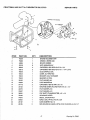
CRAFTSMAN
4000 WATT
A-C GENERATOR
580.327060
REPAIR
PARTS
"_ SUPPLIED WiTH ENGINE
12
5
ITEM
PART NO.
QTY.
DESCRIPTION
1
76236
1
ENGtNE-TECUMSEH 8HR
2
75933
1
CRADLE,, SEARS 4000
3
44624
4
MOUNT, RUBBER
4
22129
8
LOCK WASHER-5/16"
5
36223
4
CAPSCREW, HEX HEAD-5i16"_18 x 3/4"
6
33212
2
8
76220
1
CAPSCREW, HEX HEAD-5/16"-18 x 1-1/4" LONG
IDLE CONTROL COIL
9
70434
1
LEVER, I/C THROTTLE
10
70433
1
BRACKET,COIL TO ENGINE
11
70432
1
12
38150
3
BRACKE'_,I/(3 COIL
FLAT WASHER-#8
13
22264
3
LOCK WASHER-#8
14
51718
2
CAPSCREW, HE)( HD.-M4.-0.70 x 10
15
22153
1
16
22473
1
MACHINE SCREW, ROUND HEAD-#8-32 x 1/2"
FLAT WASHER-#10
17
23897
2
FLAT WASHER-#10
18
36261
2
19
70446
1
POP RIVET, STAINLESS STEEL 1/8" x .23
GOVERNOR LEVER
2o
77816
1
DECAL, CAUTION HOT
21
50923
1
MACH. SCR., PP HD. #I0-24 x 5/8"
22
22152
1
LOCK WASHER, NO. 10
23
25105
2
SCR, ROUND HD.-MACH. WITH LOCK WASHER #6-32×1/4"
15
Drawing
No. 70442
0_
'1'1
.-/
03
13
Z
2O
_>
12
,>
(..)
Q
m
Z
m
-4
23
0
\
(31
CO
\
0
4
t
,\
PO
"..I
0
7
16
\
m
21
m
-a
,-4
3
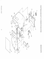
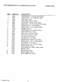
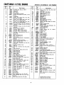
CRAFTSMAN
ITEM
4000 WATT A-C GENERATOR
580.327060
REPAIR
PART NO.
DESCRIPTION
1
24489
SCREW (TAPTITE) - No. 10-32 x 3/8" (14 REQ.)
2
24944
PLUG, BUTTON -- 1.25" DIAMETER
3
76249
PANEL, END (1 REQ.)
4
76460
BACK, PANEL SHROUD
5
68867
RECEPTACLE-
6
68759
RECEPTACLE
7
66819
BREAKER, CIRCUIT -- 20 AMP (2 REQ.)
8
6.77632
BOARD, CIRCUIT - IDLE CONTROL (1 REQ.)
9
22717-A
GROMMET
10
74769
TRANSFORMER,
11
75921
DECAL, SEARS 4000 (1 REQ.)
12
55869
SWITCH, IDLE CONTROL
13
76255
DECAL, IDLE CONTROL
(1 REQ.)
(1 REQ.)
120/240 VOLTS (1 REQ.)
- 120 VOLTS DUPLEX TYPE (1 REQ.)
(1 REQ.)
IDLE CONTROL (1 REQ.)
(t REQ.)
(1 REQ.}
14
51715
NUT, HEX- M4-0.70 (8 REQ.)
15
22264
LOCKWASHER-
16
23365
WASHER (SHAKEPROOF)
No. 8 (8 REQ.}
- No. 8 (2 REQ.)
17
75475
SCREW, PAN HD.- M4-0.7 X 10ram (6 REQ.)
18
38150
FLAT WASHER - No. 8 (4 REQ.)
19
70439
SCREW, PAN HD. - M4-0.7 X 20ram (2 REQ.)
20
76278
SHROUD, PANEL (1 REQ.)
*
43483
PLUG, CONNECTOR-
*
70438
MANUAL (I REQ.)
21
25433
GROUND LUG (1 REQ.)
22
77818
DECAL, DANGER (1 REQ.)
23
77026
DECAL, NAMEPLATE
Drawing No. 70441
17
NEMA L14-20P (1 REQ.)
(1 REQ.)
PARTS
0
'2_.
o_
27._
SUPPLIED WITH
ENGINE
6
C_
/'11
16
Z
m
--I
0
oo
".4
m
,,_
_a
_o
Sl
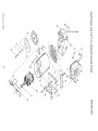
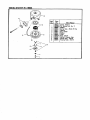
CRAFTSMAN
4000 WATT
A-C GENERATOR
580.327060
REPAIR PARTS
PART NO.
DESCRIPTION
1
60220-F
HOUSING ADAPTER (1 REQ.)
2
22O97
LOCKWASHER - 1/4" (4 REQ.)
3
22129
LOCKWASHER - 5/16" (9 REQ.)
4
43107
CAPSCREW, HEX HEAD M8-1.25 x 25ram LONG (2 REQ.)
5
76256
STATOR ASSEMBLY (1 REQ.)
6
7595O
BAR, STATOR BOLT (2 REQ.)
7
28293
RECTIFIER BRIDGE (1 REQ.)
8
44395-H
BOLT, STATOR (4 REQ.)
9
22336
SCREW - 5/16"-24 X 3/4" (4 REQ.)
10
68397
ROTOR ASSEMBLY (1 REQ.)
11
24049
BEARING, ROTOR (1 REQ.)
12
44943
CARRIER, BEARING (1 REQ.)
13
A-24044-A
BRUSH (2 REQ.)
14
23877-D
HOLDER, BRUSH (1 REQ.)
15
25105
SCREW - No. 6-32 X 1/4" (2 REQ.)
16
28092
BOLT, ROTOR - 5/16"-24 X 9.25" (1 REQ.)
17
50190
WASHER, FAN RETAINING (1 REQ.)
18
44357
COVER, FAN (1 REQ.)
19
44331
FAN, COOLING (1 REQ.)
20
76236
ENGINE - 8HP. TECUMSEH (1 REQ.)
21
72804
MUFFLER ASSEMBLY (1 REQ.)
22
60706
CAPSCREW, SOCKET HD. - 5/16"-18 x 3/4" LONG (2 REQ.)
23
52858
NUT, LOCKING FLANGE- M8-1.2514 REQ.)
24
76299
SUPPORT, MUFFLER (1 REQ.)
25
22145
FLAT WASHER - M8 (2 REQ.)
26
40976
CAPSCREW, SOCKET HD. - M8-1.25 x 20ram (2 REQ.)
27
77819
28
36223
DECAL, START/STOP (1 REQ.)
CAPSCREW, HEX HD. - 5/16"-18 x 1/2" LONG (2 REQ.)
29
70634
SUPPORT, REAR ALTERNATOR (1REQ.)
**
70438
MANUAL, OWNER'S (1 REQ.)
30
75940
DECAL, SEARS (1 REQ.)
31
67210-A
DECAL, GROUND (1 REQ.)
35
52829
CAPSCREW, SOCKET HD. - M8-1.25 x 14mm (2 REQ.)
36
52858
NUT, LOCKING FLANGE - M8-1.25 (4 REQ,)
ITEM
** NOT SHOWN
Drawing
No. 70440
19
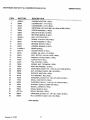
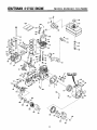
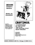
CRAFTSMAN
4-CYCLEENGINE
MODEL
NUMBER"
143.796202
I
215
6O
58
I
I
'_178
56
24
MODEL end SERIAL
NUMBERS HERE
I
I
7
i"
.i"
213
20
/
196
CRAFTSMAN
4-CYCLEENGINE
Ref.
No.
Part
No.
1
3
4
5
6
7
35385
27642
35319
27652
35326
65O561
8
9
35425
34552
34553
34554
9A
9A
34329A
34330A
9A
34331A
1o
11
11
11
17
27888
34332
34333
34334
35373A
18
19
19A
2O
21
35374
65O9O8
6.5_882
34O34
35375
22
23
24
25
33273A
650128
"35262
35376
26
27
33
35377
35319
30699C
34
35
36
37
38
39
4O
41
42
43
307OO
65O494
29642
31845
30588A
36479
29193
35378
33369
650836
49
5O
51
52
53
54
55
56
29916
29826
29216
33454
29918
65O548
30322
650832
57
650833
58
59
6O
62
66
66
35555
35499
35554
35540
27878A
27880A
67
34035
MODEL
Ref.
No.
Part Name
Cylinder (Incl. Nos. 3, 4 Et 5)
Plug, Pipe
Seal, Oil
Pin, Dowel
Baffle, Blower housing
Screw, Hex washer hd. Durlok, !/4-20
x 5/8
Crankshaft
Piston, Pin 8 Ring Assy. (Incl. Nos.
9A, 10 6" 11} (Std.)
Piston, Pin 8- Ring Assy. (Incl. Nos.
9A, 10 _ 1t) (.010 oversize)
Piston, Pin El" Ring Assy. (Incl. Nos.
9A, 10 _ 11) (.020 oversize)
Piston 8 Pin Assy. (Incl. No. 10} (Std.)
Piston 8 Pin Assy. (Incl. No. 10) (.010
oversize)
Piston Ef Pin Assy. (tncl. No. 10} [.020
oversize)
Ring, Piston pin retaining
Ring Set, Piston (Std.)
Ring Set, Piston (.010 oversize)
Ring Set, Piston [.020 oversize)
Rod Assy., Connecting [Incl. Nos. !8,
19 _ 19A)
Dipper, Oil
Bolt, Connecting rod
Bolt, Connecting rod
Lifter, Valve
Camshaft (Mechanical
Compression
ReleaseJ
Extension, Blower housing
Screw, Hex hd. Seres, 10-24 x 1/2
Gasket, Cylinder cover
Cover Assy., Cylinder (Incl. Nos. 26,
27 _ 37)
Bushing, Cylinder cover
Seal, Oil
Rod Assy., Governor Ilncl. Nos. 34 8
35)
Yoke, Governor
Screw, Fil. hd. Sems, 6-40 x 5/16
Ring, Retaining
Shaft, Governor
Spool, Governor
Washer, Flat
Ring, Retaining
Gear, Governor (lncl. No. 39)
Bracket, Governor gear
Screw, Hex washer hd. thread formmg, 10-24 x I/2
Clamp, Governor lever
Screw, Hex washer hd., !0-32 x 3/4
Locknut, Hex "Keps", 10-32
Lever, Governor
Washer, E.T. Lock
Screw, Hex washer hd., 8-32 x 5/16
Locknut, Hex "Keps", 8-32
Screw, Hex washer hd. Powerlok,
1/4-20 x 1-11/16
Screw, Hex washer hd. Powerlok,
1/4-20 x I-3/16
Dipstick, Oil
"0" Ring
Tube, Oil fill
Clip, FilJtube
Valve, Exhaust (Incl. No. 70) {Std.)
Valve, Exhaust (InoL No. 70) (1132"
oversize)
Valve, Intake (Incl. No. 70) {Std.)
67
68
68A
69
70
76
78
79
80
81
82
83
96
97
99
99A
100
101
102
103
104
105
106
t07
108
109
110
111
112
114
115
117
118
119
120
130
140
143
144
145
146
147
148
155
156
157
158
159
160
161
168
169
170
171
172
173
174
Part
No.
NUMBER:
143.79620;
Part Name
34O36
Valve, Intake (Incl. No. 70) (1/32"
oversize)
27882
Cap, Upper valve spring
34689
Seat Assy., Intake valve
27881
Spring, Valve
32581
Cap, Lower valve spring
32589
Key, Flywheel
611090
Flywheel
65O88O
Washer, Lock
650881
Nut, Flywheel
65O872
Stud, Solid state mounting
35135
Solid State Assy.
65o814
Screw, Torx Hex washer hd. Sems,
t0-24 x 1
"34041A
Gasket, Cylinder head
34030
Head, Cylinder
34251
Resistor Spark plug (Champion RJ17LM or equivalent}
27276
Cover, Spark plug
650691
Washer, Flat
650727
Screw, Speciat hex hd. tapped,
5/16-18 x 1-3/4
65069o
Washer, Flat
650694A
Screw
"27896A
Gasket, Breather
28423
Body, Breather
28424
Element,Breather
28425
Cover, Breather
35350
Tube, Breather
650t 28
Screw, Hex hd. Seres, 10-24 x 1/2
30845A
Bolt, Governor spring adjusting
3345O
Nut, Lock
30886A
Spring, Extension
29752
Nut _ Lockwasher, 1/4-28
*33263
Gasket, Carburetor
34707
Pipe, Intake
30088A
Screw, Fil. hd. Sems, 1/4-28 x 1
650378
Screw, Torx Fil. hd. Seres, 5/16-18 x
1-1/8
"27915A
Gasket, Intake pipe
33375C
Housing, Blower
338_
Link, Governor-to-throttle
6507_
Screw, Hex hd. spinlock thread formrag, 5/16-18 x 3/4
29747B
Screw, Hex hd. Seres, 5/16-24 x 21/32
33013
Cover, Starter hole
650760
Screw, Pan hd. taptite, 8-32 x 3/8
65O89O
Washer, Lock
30747
Clip, Shorting
33267
Bracket, Air cleaner
28820
Screw, Fit. hd. Seres, 10-32 x 1/2
33266
Bracket, Air cleaner
"27272A
Gasket, Air cleaner
33268
Element, Air cleaner
33269A Cover, Air cleaner
65O513
Nut, Wing
33272.A Cover, Cylinder head
650802
Screw, Hex washer hd. taptite, 1/4-20
x 5/8
341_
Plate, Fuel tank mounting
62713
Screw, Hex hd., 5/'16-18 x 5/8
34158
Bracket, Fuel tank
65O561
Screw, Hex washer hd. Durlok, 1/4-20
x 5/8
650665
Screw, Hex washer hd. thread cutting,
1/4-15 x 7/8
*Indicates Parts Included in
Gasket Set, Ref. No. 2!5.
2]
CRAFTSMAN
4"CYCLE
ENGINE
Ref.
No.
175
176
177
178
186
194
195
196
199
210
Part
No.
Ref.
No.
Part Name
34156A
35355
30705
2646O
27930A
35287
35446
29752
35392
34346
CARBURETOR
MODELNUMBER"
143.796202
212
2t3
215
Tank, Fuel (IncL Nos. 176 8 178)
Cap, Fuel tank
Line, Fuel
Clamp, Fuel line
Gasket, Exhaust
Hub, Starter
Screen, Starter
"Nut 8 Lockwasher, 1/4-28
Plug, Starter
Decal, Instruction
NO,
Part
No.
632351
590633
33279G
Part Name
Carburetor {Incl. No. 115)
Starter, Rewind
Gasket Set (Incl. items marked
"1
RPM Setting:
High Speed: 3750.
*Indicates Parts Included in
Gasket Set, Ref. No. 215.
632351
!Ref, Part
No,
"-
14
i
I
2
3
4
5
7
8
9
10
11
_-16
22
12
No,
632351
631776
631970
631778
6505O6
63O768
63O738
65O417
631812
630735
631763
*630748
*631027
*631021
13
14
15
16
17
18
631022
632019
*631024
631867
631184
631183
27110
"632239
23
24
25
26
28
29
3O
31
*630740
*632281
*631028
632164
632043
631971
630739
632347
Part
Name
Carburetor
Shaft 8 Lever Assy., Throttle
Spring, Throttle return
Shutter, Throttle
Screw, Throttle Et Choke shutter
Spring, Idle regulating screw
Spring, Main adiustment
screw
Screw, Idle regulating
Shaft Et Lever Assy., Choke
Spring, Choke positioning
Shutter, Choke
Plug, Welch
Plug, Welch
Inlet Needte, Seat Et Clip Assy.
(Incl. No. 13)
Clip, Inlet needle
Float, Carburetor
Shaft, Float
Bowl, Float
Washer, Fiat
Washer, Felt
Gasket, Bowl-to-body
Adjustment
Screw
Assy.,
Main
[tncl. Nos. 5A, 21, 23 6" 301
"0" Ring, Adjustment
screw
Screw, Idle adiustment
Gasket, Rowl-to-body
Fitting, Fuel
Spring, Choke return
Seal, Dust
Washer, Flat
Repair Kit {IncI. items marked *)
12
l_f.
No.
1
2
3
4
8
9
10
11
12
23
Part
No.
59O633
_Ai
58O60O
590861
59O627
59O641
59O6O1
59O632
5_451A
59O629
59O387
59O634
Part Name
StaRer, Rewind
Pin, Spring (Inct. No. 7)
We=her
Spring A_y.,
Brake _t Dog
Retainer
Dog, Starter
Washer
Pulley
Rope, Starter
Spring _ Keeper A_y.
Handle Auy.,
Starter
Housing A_y.,
Starter
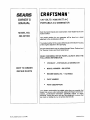
SEA/R@
OWNER'S
£RRFTSMRN °
120 VOLTS / 4000 WATT A-C
MANUAL
PORTABLE
MODEL NO.
Each Generator has its own model number. Each engine has its own
model number.
A-C GENERATOR
580.327060
The model number for your generator will be found on a decal
attached to the control panel shroud.
The model number for the engine willbe found on the Blower Housing
of the engine adjacent to the spark plug.
All parts listed herein may be ordered through Sears, Roebuck and
Co. Service Centers and most Retail Stores.
WHEN ORDERING
REPAIR PARTS, ALWAYS
FOLLOWING
INFORMATION:
•
HOW TO ORDER
PRODUCT-
PORTABLE
•
MODEL
•
ENGINE
•
PART NUMBER
•
PART DESCRIPTION
GIVE THE
A-C GENERATOR
NUMBER-580.327060
REPAIR PARTS
MODEL NO.-
143.796202
Your Sears merchandise has added value when you consider that
Sears has service units nationwide staffed with Sears trained technicians .... professional technicians specifically trained on Sears
products, having the parts, tools and the equipment to ensure that
we meet our pledge to you, we service what we sell.
Put No. 80059 R_vision 3 (1111/90)
Printed in U.S.A.