1
\\
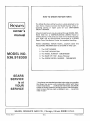
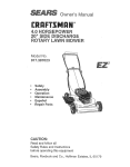
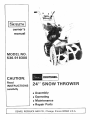
owner's
manual
MODEL NO.
536.918300
CAUTION:
Read
INSTRUCTIONS
OWE
carefully
• Assembly
• Operating
e Maintenance
• Repair Parts
I
SEARS,
ROEBUCK
AND
CO., Chicago,
Illinois
60684
U.S.A.
HAZARD TO OPERATOR,
BYSTANDERS,
PROPERTYOR
Look for this symbol, It means -- ATTENTION!
BECOME
EXIST,
OWNERS INFORMATION
Page
2
...........................
MAINTENANCE AGREEMENT .......
:. ..............
"WARRANTY .......................................
OPERATIONAL PRECAUTIONS ......................
Contents of Shipping Carton ......................
Tools Required for Assembly
......................
ASSEMBLY ......................................
Handle Assembly .................................
Controls Assembly
..............................
Skid and Gage Wheel (Height) Adjustment
.........
OPERATION .....................................
Operating Controls ..............................
Snow Thrower Operation .........................
Before Starting Engine
..........................
To Start Engine ..................................
ADJUSTMENTS
.................................
Drive Belt Adjustment
...........................
Chute Deflector Cable Adjustment
.................
Power Clutch Cable Adjustment
...................
Wheel Drive Control Adjustment
...............
Record the following
information
UNIT MAY
ALERT! A
Page
impeller/Auger
Control Cable Adjustment
.........
Carburetor Adjustment
..........................
Spark Plug Adjustment
..........................
MAINTENANCE
................................
Drive Belt Replacement .......................
Shear Bolt Replacement
.........................
Roller Chain Replacement
.......................
Transmission Replacement .......................
Snow Chain Removal ............................
Lubrication
..................................
Engine Service ..................................
STORAGE ........................................
Engine Storage
.................................
Unit Storage ....................................
LUBRICATION CHART .............................
UNIT REPAIR PARTS ...........................
ENGINE REPAIR PARTS ........................
TRANSMISSION REPAIR PARTS ....................
SERVICE HELPS CHART ...........................
HOW TO ORDER REPAIR PARTS ...................
2
2
3
4
4
4-6
4
4,5
6
6-8
6,7
7
7,8
8
8-10
8,9
9
9
9,10
10
10
10
10-!2
10,11
11
11
1t
11
11,12
12
12
12
12
13
14-2!
22-25
26
27
28
about your unit so that you will be able to provide it in case of loss or theft.
DATE PURCHASED:
MODEL NO.:
536,918300
CODE NO.:
STORE WHERE PURCHASED: ADDRESS
CITY
STATE
The Craftsman Warranty, plus a Maintenance
nearest Sears store for details.
TELEPHONE
Agreement,
provide maximum value for Sears products. Contact your
t IIRFIrSNRN. WARRANTY
FULL ONE YEAR WARRANTY
ON CRAFTSMAN
SNOW THROWER
If this Snow Thrower fails to perform properly due to a defect in material or workmanship within one year
from the date of purchase, Sears wilt repair it, free of charge.
WARRANTY SERVICE IS AVAILABLE BY SIMPLY CONTACTING THE NEAREST SEARS STORE OR
SERVICE CENTER THROUGHOUT THE UNITED STATES.
This warranty gives you specific legal rights, and you may have other rights which vary from state to state.
SEARS, ROEBUCK AND CO.
SEARS TOWER
BSC 41-3
CHICAGO, IL 60684
--2--
observed
to prevent
the possibility
of injury
damage.
Please
the normal
followingprecautions
operationalbe
Itis imperative
in operating
and handling
your or
Snow
Thrower
thatread
certain
precautions before you assemble or use your new Snow Thrower.
_r_
TRAINING
5. Stop engine
whenever
you leave the operating
position,
before unclogging
the auger/impeller
housing
or dischargechute,
and making any repairs, adjustments,
or inspections.
1. Wear safety glasses or eye shields when assmbling
or operating snow thrower.
2. Read the Owner's Manual carefully. Be thoroughly
familiar with the controls and the proper use of the
equipment.
Know how to stop the unit and disengage
the controls quickly.
6. Take all possible precautions when leaving the
machine unattended. Disengage the auger/impeller,
shift into neutral, stop the engine, and remove the key.
3. Never allow children or young teenagers to operate
equipment and instruct them to stay away from the unit
while it is operating. Never allow adults to operate equipment without proper instruction.
7. When
cleaning,
repairing,
or inspecting,
certain
auger/impeller
and
all moving
parts
stopped.
Disconnect
spark plug wire and keep wire
from
4. Keep the area of operation clear of all persons,
especially small children and pets.
plug
to prevent
accidental
make
have
away
starting.
PREPARATION
8. Do not run engine
indoors,
except when
starting
engine and for transporting
snow
thrower
in or out of
building.
If for some reason engine must be run indoors,
open outside
doors.
Exhaust
fumes
contain
carbon
monoxide
which is odorless
and deadly poisonous.
I. Thoroughly inspect the area where the equipment
is to be used and remove all door mats, sleds, boards,
wires, and other foreign objects.
9. Do not clear snow across the face of slopes. Exercise extreme caution when changing direction on slopes.
Do not attempt to clear steep slopes.
2. Disengage all clutches and shift into neutral before
starting engine or motor.
10. Never operate snow thrower without guards,
plates or other safety protective devices in place.
3, Do not operate equipment without wearing adequate winter outer garments. Wear footwear which will
improve footing on slippery surfaces.
11. Never operate snow thrower near glass enclosures,
automobiles, window wells, drop-off,
etc. without
proper adjustment of snow discharge angle.
5, Exercise caution to avoid slipping or falling, espe_
cially when operating in reverse.
4. Handle gasoline with care - it is highly flammable.
12. Do not overload machine capacity
clear snow at too fast a rate.
A. Use only approved gasoline containers.
B, Never remove fuel tank cap or add gasoline to a
running or hot engine or fill fuel tank indoors.
C, Replace fuel tank cap securely and wipe any
spilled gasoline at once.
by attempting tc
13. Do not change engine governor settings, The
governor controls the speed and protects the engine
from excessive, damaging speeds.
14. Never operate machine at high transport speeds on
slippery surfaces. Use care when backing.
D. Check your fuel supply before each use, allowing space for expansion as the heat of the engine
and/or sun can cause gasoline to expand.
15. Never direct discharge at bystanders or allow anyone in front of unit.
5. Use a grounded three wire plug-in for all units with
electric starting motors.
16. Disengage power to auger/impeller
porting unit or when unit is not in use.
6. Adjust auger housing height
crushed rock surfaces.
17. Use only accessories approved by manufacturer of
the snow thrower (such as tire chains, electric start kits,
etc).
to clear gravel or
7. Never attempt to make any adjustments,
where required, while engine is running,
except
when trans-
18. Never operate the snow thrower without good
visibility or light. Always be sure of your footing and keep
a"firm hold on the handles and walk. never run.
8. Let engine and machine adjust to outdoor temperatures before starting to clear snow.
MAINTENANCE
OPERATION
AND
STORAGE
1. Do not put hands or feet near rotating parts. Keep
clear of discharge opening at all times.
1. Check shear bolts, engine mounting bolts, etc., at
frequent intervals for proper tightness to be sure equipment is in safe working condition.
2. Exercise extreme caution when operating on or
crossing a gravel drive, walks, or roads. Stay alert for
hidden hazards or traffic. Do not carry passengers.
2. Run machine a few minutes after throwing snow to
prevent freeze up of auger/impeller.
3. After striking a foreign object, stop the engine,
remove wire from spark plug, thoroughly inspect the
snow thrower for any damage, and repair the damage
before restarting and operating the snow thrower.
4. If the u_nit should start to vibr_te___l[V_stop
the engine and check immediately for the cause. Vibra-"
tion is generally a warning of trouble,
_L
--3--
3. Never store gasoline or equipment with gasoline in
the tank inside of a building where fumes may reach an
open flame or spark. Never store your snow thrower for
prolonged periods (more than 15 days) with gasoline in
the fuel tank. Store gasoline and your snow thrower in a
locked safe storage area secure from children and others.
CONTENTS
OF SHIPPING
CARTON
1 - 24 inch Snow Thrower (completely
handles,
controls
and headlight),
1 - Can of Engine Oil
1 - Upper Chute Control Rod
1 - Left Hand Handle Assembly
1 - Right Hand Handle Assembly
(with
I - Control Pane_ Assembly
1 - Bag of Assembly
Parts Containing:
I - 3A inch Flatwasher
assembled
clutch
except
DANGER
for
The operation
of any powered
equipment
can result
in foreign objects
being thrown
into the eyes, which
can result in severe eye damage.
Always
wear safety
glasses or eye shields while assembling
or operating
Snow Thrower.
lever attached)
HANDLE
Right handle
has a lever (power clutch) attached
to upper
end. Nuts used to attach lower end of handles are attached to
inside of side frame.
2 - 5/16 inch Split Lockwasher
10 - Formed (curved) Washers
4 - No. 10 x 1/2 inch Hex Head Screws
4 - No. 10 Locknuts
2 - 5/16 x 5/8, inch Hex Head Screws
2 - 5/16 x 1 inch Hex Head Screws
8 - 5/16 x 13A inch Hex Head Screws
8 - 5/16
inch Locknuts
1 - 3/_ x 3A inch Hex Head'Screws
1 - 3_ inch Locknut
1 - Cable C_amp (meta!)
2 - Knobs (for Throttle
and Impeller/Auger
Drive Levers)
1 - Bag of Shear Bolt Replacement
Parts (Not used in assembly) Containing:
3 - 5/16
x 13/_ inch Shear Bolts
3 - 5/16 inch Locknuts
I - Instruction
Sheet
TOOLS
REQUIRED
FOR
ASSEMBLY
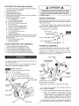
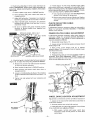
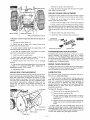
1. Attach
right
lower handle
to side of side frame as
shown in figure 2. Handle grip should be tilted down and out
when handle is properly
installed.
"2. Repeat
step
RIGHT
1 for left handle.
HANDLE
FORMED
5/16
x 1 INCH
5/16
WASHER
SCREW
_
x % INCH SCREW
5/,16 INCH SPLIT LOCKWASHER
CONTROLS
POWER CLUTCH LEVER
IMPELLER/AUGER
CONTRO.L
RIGHT
HANDLE
assembled.
HANDLE
CHUTE
DEFLECTOR
CABLE
To
LEVER
BOTTOM
NUT
LEFT HANDLE
,TTLE CONTROL
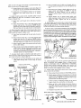
3.
CHUTE DEFLECTOR
CABLE BRACKET
or left hand as you face the unit
completely
as follows:
to handles as shown
in figure
lower screw only on left side.
2. Attach
chute
deflector
lever as shown
in figure
3.
NOTE:
Place a 5/16
inch
flatwasher
between
lever
assembly
and handle at top screw position.
RIGHT
Figure 1 shows the Snow Thrower
complete
the assembly,
proceed
_
ASSEMBLY
1. Attach control
panel
NOTE: Attach panel with
2 - 7/16
inch Wrenches
(or adjustable
wrenches)
2 - 9/16
inch Wrenches
(or adjustable
wrenches)
1 - Hammer (plastic or rawhide
head recommended)
Snow Thrower
is right
operator
position.
L
ASSEMBLY
1 - 3/8 inch Wrench
(or adjustable
wrench)
1 - 5/16
inch Wrench
(or adjustable
wrench)
2 _ V2 inch Wrenches
{or adjustable
wrenches)
Your
from
SIDE FRAME
ONTROL
PANEL
LEVER
TOP NUT
CHUTE
DEFLECTOR
LEVER
DRIVE coNTROL
CHUTE
LEFT HANDLE
CHUTE
LEVER
r
5/16
INCH
FLATWASHER
LEVER
DEFLECTOR
All screws shown are 5/16
All Iocknuts
A formed
shown are 5/16
x 13,'_inch.
inch.
washer is used on inside of handte at all screw locations.
PANEL
3. To attach
cable),
CABLE CLAMP
SIDE
proceed
A.
chute
deflector
cable
bracket
(attached
to
as follows:
Place chute deflector
Iever in lowest
(forward)
notch.
B. Grasp
chute
deflector
cable
bracket
and pull
down until a 5/16 x 1_'_ inch screw can be placed
through
bracket
and
through
left
handle
as
shown
in figure 3. NOTE:
Only one of holes in
cable bracket is large enough for mounting
screw.
FRAME
_GAGE
4. Cable length will need to be adjusted
if chute deflector
lever wilf not move all the way up to top notch in bracket or if
WHEEL
--4--
cable
down
is loose and sags when
to last notch. To adjust
A.
Loosen
bottom
and tighten
lever
cable:
nut on power
top nut
until
is pushed
clutch
lever will
all
cable
reach
B. Push
the way
(figure
4)
top notch.
shown
in figure
A.
lever assembly
(other end of
of engine}
to control
panel as
up through
slot
in left side
of control
B. Attach with two No. 10 x 1/2 inch hex washer t_ead
screws
and two No. 10 Iocknuts.
NOTE:
Before
tightening
screws and locknuts, check to make sure
that lever does not rub side of slot in control panel.
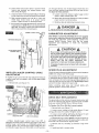
6. Attach impeller!auger
drive control lever (other end of
cable is attached
on right side of unit below gas tank) to
controt
panel as shown in figure 4 by:
A.
Insert
panel
lever
up through
slot
in right
side
of control
drive
control
of
cable
replace,
hole
in
do not tighten,
top
9. Remove
the
1 inch
screw
and locknut
from
pivot
block
(part of universal
bracket) located on end of lower rod (figure
5). insert lower end of upper rod onto pivot block in universal
bracket (figure 5) on lower chute control rod and securewith
the removed screw and Iocknut. CAUTION:
Do not tighten
Iocknut
against
universal
bracket.
This
must be loose enough
to allow universal
LOWER CHUTE
CONTROL ROD
BRACKET
screw
and nut
to move freely.
FORMED WASHER
8,. _jl_._
5/16 INCH LOCKNUT
_._._
BRACKET _
CHUTE
cable to handle
BRACKET
D. Place a knob onto throttle
and impeller/auger
drive
controi
tevers and tap firmly with a hammer
until
knobs will not pull off. CAUTION:
Knobs are made
of plastic and will break if hit too hard. A plastic or
rawhide
hammer
is recommended.
5/16x1¾
INCH SCREW
7. A power clutch cabte is attached
under belt cover in
front of engine. Cable shoutd wrap around left side of engine
and under carburetor.
Attach cable by:
A.
up through
but
8. Attach upper chute control rod and upper chute control
rod bracket (mounted
on rod) to bottom side of left handle
(figure 5) with two 5/16
x 13/4 inch hex head screws, two
5/16 inch Iocknuts,
and two formed washers.
B. Attach with two No. 10 x 1/2 inch hex washer head
screws
and two No. 10 {ocknuts.
NOTE:
Before
tightening
screws and ]ocknuts, check to make sure
that lever does not rub side of slot in control panel.
C. Attach impeller/auger
with a cable clamp.
and
D. Tighten
bottom
nut on power clutch
cabEe until
cable stop (figure 4) just clears top end of threaded
portion
of cable.
Tighten
top nut to complete
assembly.
4 by:
Insert lever
panel.
end
panel
Hook loop end of power clutch cable over pin on
power
clutch
lever (figure
4). NOTE:
It may be
necessary
to loosen
bottom
nut on cable
to
lengthen
cable enough to hook over pin on clutch
handle.
C,
B. Loosen top nut and tighten
bottom
nut to remove
looseness
from
cable when
lever is in bottom
notch.
5_ Attach
throttte
control
cable attached
to left rear
threaded
control
nut.
UPPER CHUTE
CONTROL ROD
LOWER CHUTE
CONTROL ROD
Remove top nut from threaded
end of cable and
slide cable through
slot in lower edge of control
panel.
10.
Check
WHEEL
sprocket
end of chute
DRIVE
control
CONTROL
rod to make
RODS
sure
teeth
on sprocket
fully
engages
holes in flange
around
bottom
of discharge
chute.
If adjustment
is necessary,
simply
loosen screws
attaching
lower chute
control
rod
bracket
to main frame and sIide bracket up or down until
teeth
on sprocket
1 I. Attach
drive control
A.
engages
holes
upper wheel drive
rod as follows:
fully
control
Place wheel
B. Attach
screw
drive control
in flange.
rod to lower
wheel
lever in NEUTRALposition.
upper and lower rod ends with a _ x 3,4inch
and 3/8inch Iocknut as shown in figure 6 and
tighten securely.
NOTE: If rod ends do not line up,
proceed with the following
steps.
C. Loosen
upper
screws
wheel
in retaining
drive
bracket
rod (below
at top end
control
of
panel).
D. Move rod left or right (make sure lever stops in
NEUTRAL position)
until holes in rods line up and
place 3,_x 3,4inch screws through both rods. Tighten
securely.
E. Retighten
UPPER WHEEL
3/S _NCH
DRIVE
LOCKNUT
loosened
screws
CONTROL
ROD
on retaining
bracket.
_
-- ox ,NcNsc
LOWER WHEEL DRIVE CONTROL ROD
--5 m
SKID and GAGE WHEEL
(Height) ADJUSTMENT
A CAUTION
The operation
of any powered outdoor equipment
in foreign
objects
being thrown
into the eyes,
result
in severe
eye damage.
Always
wear
safety
glasses
or eye shields
before beginning
snow thrower
operation.
We
recommend
Wide
Vision
Safety
Mask
for over spectacles
or
standard
safety
glasses,
available
at
SEARS Retail or Catalog Stores.
A
For packing purposes, the gage wheels on this unit
were adjusted all the way up to lowest height
position, Adjust height as instructed below before
using snow thrower,
This unit is equipped with a pair of skids mounted on the back
side of the auger housing and a pair of gage wheels located
on the outside of the auger housing. Both the skids andgage
wheels are used to elevate the front of the machine up to 1
inch. Figure 7 shows both parts.
Familiarize
Operational
When removing snow from hard surface area such as paved
driveway or sidewalk, we suggest use of gage wheels only, to
elevate front of machine to desired height. To change height
of gage wheels:
up and tighten
have been set.
skids
to full
Operating
follows:
(figures
•
controls
desired
with
8 & 9) and their functions
the
are as
Power Clutch Lever - The power clutch lever controls
forward or reverse
motion of the unit when the wheel
unit motion and impeller/auger
rotation
slowly but firmly and all the way down
grip.
UP position
•
AUGER
HOUSING
stop. Engage
against hand
Impeller/Auger
Drive Control Lever - Used to disengage power to impeller/auger
without interfering with
power to drive wheels. Pull up to engage. Push down to
disengage.
NOTE: Power clutch lever must be in released (disengaged)
position before impeller/auger
lever position is changed.
e Throttle
Control Lever - This snowthrower
is equipped
with a control panel mountedthrottle
control lever used
to control speed of engine, There are three positions
on
the throttle
control - Stop - Slow - Fast.
LOW SE'n'IN G
HIGH SETTING
O Wheel
SKID
,INT|NG
SCREW
FLATWASHER
Drive
Lever
Choice
- Used to select desired
of five forward
speeds,
unit
neu-
_) Chute Deflector
Lever- The distance snow will be discharged
can be adjusted
by raising
chute deflector
(figure 8) for more distance,
or lowering
for less distance. Pull lever up to top notch for most distance.
Push
lever down to bottom
notch for least distance.
SKID
BOLT
When
removing
snow from rock or unpaved
construction;
we suggest you raise the front of the machine with the skids.
To raise the machine
with the skids:
DANGER
Do not put
the engine
1. Loosen the skid mounting
nuts (figure 7) and push the
skid down until the front of the machine
is raised to desired
mounting
Control
speed or direction.
tral and reverse.
GAGE WHEEL
SHOULDER
Retighten
and
drive control lever is in the appropriate
position. When
the operator's
hand is removed from the power clutch
lever, tension is removed
from drive belts, therefore
LOCKNUT
height.
equipment
CONTROLS
3. Set wheel on other side at same height.
4. Loosen, pull
after gage wheels
the
OPERATING
1. Remove Iocknut on shoulder bolt through gage wheel
(figure 7).
2. Relocate shoulder bolt into hole representing
height and replace Iocknut.
yourself
with
Precautions,
can result
which can
hands in or near the deflector
is running.
chute
while
nuts.
IMPELLER/AUGER
2. Set skid on other side at same height. NOTE: Be sure
that front of unit is set at same height on both sides.
CONTROL
LEVER
THROTTLE CONTROL LEVER
CHUTE
DEFLECTOR LEVER
L DRIVE CONTROL LEVER
DANGER
Be certain
to maintain
proper ground
clearance
for
your particular
area to be cleared.
Objects
such as
gravel,
rocks
or other
debris,
if struck
by the
impeller/auger,
may be thrown
with sufficient
force
to cause personal
injury
or property
damage.
POWER
CLUTCH
LEVER
%
OIL FILL CAP
& DIPSTICK
--6--
@ Chute Control
Rod - Used to change direction
of snow
discharge.
Turn handle counterclockwise
to turn chute
to left. Turn handle clockwise
to turn chute to Hght. All
snow can be discharged
to one side by changing
chute
direction
when changing
direction
of travel.
@ Choke Lever - Set choke
to start engine.
lever to FULL CHOKE
@ Primer Button - Used to inject fuel directly
tor manifold
to insure fast starts.
thrower
unit.
Switch
engine
- Switch must be turned to ON position
and turned
to OFF position
to stop
•
Starter
starter.
Handle
- This
with
along
"-,
the
2.
x
to push the
drive
control
DANGER
attempt
to
lodged
in
precautions"
Move
Do not attempt
impeller/auger
remove
auger
1, Move
impeller/auger
OFF position.
fl4/-
lever to the ON position.
the drive mechanism:
Release the power
the wheel
drive
control
lever
to the
A
a recoil
CHOKE LEVER
_--
path.
NEUTRAL
position.
Set
lever to the OFF position.
Do not
become
following
_==
control
clutch lever to begin impeller/auger
motion.
As the unit starts to move,
on the bandies and guide the snow
the cutting
6. To disengage
clutch
lever.
Set
into carbure-
Ignition
to start
engine.
is equipped
5. Press the power
rotation
and forward
maintain
a firm hold
position
8
unit
4. Set the impeller/auger
wheel
any
item
that
without
taking
drive
drive
control
control
lever
may
the
lever
to
to NEUTRAL
position.
IGNITION
SWITCH
SNOW
1(
.I
THROWER
CHUTE
-"
CONTROL
OPERATION
a building
as hidden objects
force to cause damage.
To engage
follows:
the self-propeINng
1. Start
Engine.
the
engine
drive
could
be thrown
mechanism,
as described
in paragraph
4.
Turn
5.
Remove
BEFORE
A can of high
unit.
as
is for extra
deep,
To Start
wet,
position.
plug.
Release pressure
from power
drive control lever to NEUTRAL
STARTING
quality
5W-20
ENGINE
motor
oil is supplied
1. Remove
the oil cap and dipstick
crankcase
to the FULL line on dipstick
pints),
chute control
rod (figure 9), position
the
so as to discharge
the snow with the wind.
1 position
to OFF
spark
position.
position.
the oil cap and dipstick
3. Always
check oif level before
after each five hours of continuous
Do not overfill.
3. Select
proper speed for snow conditions
as outlined
below and set wheel drive control
lever to desired position.
A. Number
key
lever to STOP
To stop backward
motion:
clutch
lever. Return wheel
2. Replace
2. Using
the
discharge
chute
throttle
7. To move unit backwards:
Place wheel
drive control
lever in REVERSE position and press the power clutch lever.
with
proceed
Move
6. Do not place your
hands in the auger
or
discharge
chute.
Use
a pry bar. The
engine
compression
could cause the auger to rotate sharply
when lodged item is removed,
if above precautions
are not followed.
ROD
The most
effective
use of the snow
thrower
wilt be
establishsd
by experience,
taking
into consideration
the
terrain,
wind
conditions
and the depth and weight
of the
snow. It is the wind conditions
and building
location
which
will determine
the direction
of the discharge
chute. Since the
wind will tend to blow the discharged
snow back into the
cleared
area, it wilt be necessary
to change
the chute
direction
to offset this condition.
NOTE: Do not throw snow
towards
sufficient
3.
with
your
(figure
10) and fill
(approximately
1V2
and tighten
securely.
starting
the engine and
use. Add oil as required.
OIL FILL CAP
& DIPSTICK
heavy
SROW,
B. Number
2 position
is for deep, wet, heavy snow.
Experience
will help make choice between
position
1 and 2.
C. Number
D.
3 position
Number 4 position
over bare or plowed
light
is for light
fluffy
snow.
is mainly for transporting
unit
areas, but may be used for very
snow.
E. Number 5 position
or plowed areas.
is for transporting
DANGER
unit over bare
A
The moment the wheel drive control lever is set in a
position other than NEUTRAL and the power clutch
lever on the right hand grip is pressed, the snow
thrower will move forward.
IGER
GEAR
--7--
CASE
OIL
FILL
PLUG
4. Change crankcase oil after the first 2 hours of operation
and after each 25 hours of operation thereafter, or at the
beginning of each season, whichever comes first.
choke position.
NOTE: Allow the engine to warm up for a
few minutes
as the engine will not develop full power until it
reaches operating
temperature,
5. To drain the oil, see paragraph
Maintenance section of this manual.
9. Run engine
at or near top speed.
NOTE:
To help
prevent
possible
freeze-up
of rewind
starter,
proceed
as
follows
after each snow blowing
job:
Lubrication
in
6. Fill gas
tank
with
clean,
fresh,
unleaded
grade
automotive
gasoline.
Leaded regular
grade gasoline
is an
acceptable
substitute.
Do not use Ethyl or high octane
gasoline,
Be certain container
is clean and free from rust or
foreign
particles.
Never use gasoline
that may be stale fiom
long periods of storage
in the container.
A
A. With engine running,
continuous
fuil arm
Pulling
sound.
Never fill the gas tank while engine
is running or is
hot.
Immediately
wipe
off any spilled
gasoline
before attempting
to start engine.
A. With
engine
not running,
wipe
all snow
and
moisture
from carburetor
cover in area of control
levers. Also move control
levers backward
and
forward
several times.
7. Check oil level in gear case by removing oil leve! fill plug
(figure 10). Oil should be visible in hole. If not, insert a funnel
that has an adjustable
neck and add SEARS SAE-30
(or
equivalent)
engine
oil until it starts
to run out of hole.
Replace plug and tighten securely.
IMPORTANT:
After each use of the snow thrower,
stop the
engine,
remove
the ignition
key, remove
all accumulated
snow from the unit and wipe clean. Store the snow thrower
in a protected
area.
ENGINE
NOTE: To prevent or cure iceing of cables and control, a deicer can be used. De-icer
is available
in the automotive
The snow thrower
engine is equipped
with a recoil starter.
The operation
of this engine
is controlled
by the throttle
control lever (figure 8). Before starting the engine, be certain
that you have read and followed
all the instructions
on the
preceding pages.
department
WARNING
areas
feet,
parts
exceed
wheel
2. Move
position.
impeller/auger
4.
Move
drive
ignition
throttle
of
muffler
150 ° F, Avoid
1, Move
position.
3. Rotate
position.
SEARS
Store.
attention
Also
be
to instruction
extra careful
comes in contact
with
on or near engine.
poorly
carbon
muffler
on
that
the
no
or any other
de-icer
de-icer
hot area
hair and loose clothing
away from
on engine and snow thrower.
- Temperature
may
enclosed,
contains
gas.
nearest
CAUTION
DANGER
Keep hands,
any moving
of your
Pay close
container.
Never
run engine
indoors
or in
ventilated
areas.
Engine
exhaust
monoxide,
an odorless
and deadly
of starter rope wilt produce a loud clattering
This is not harmful
to the engine or starter.
10. To stop forward
motion,
release
power
clutch
lever
(figure
8) on right handle.
To stop engine,
move throttle
control lever to STOP position
and move ignition switch key
to OFF position. NOTE: To help prevent possible freeze-up of
engine controls,
proceed as follows
after each snow blowing
job:
DANGER
TO START
pull starter rope hard with a
stroke
three
or four times.
control
switch
control
lever
control
(figure
lever
key (figure
lever
and
these
(figure
nearby
areas,
CAUTION
8) to NEUTRAL
(figure
8) to OFF
9) clockwise
9) to FAST
5. Move choke lever (figure 9) to FULL CHOKE
NOTE:
Do not choke a warm engine.
6. Push primer button
prime a warm engine.
(figure
9) 2 times.
Always
repairs
NOTE;
DRIVE
remove the spark
or adjustments,
BELT
plug
before
making
any
ADJUSTMENT
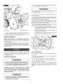
This unit is equipped with two drive belts located just in front
of engine under belt cover (figure 11 ). Figure 12 shows both
belts and idler pulleys.
Belt nearest
engine
is unit drive
(wheels)
belt.
Other
belt
(farthest
from
engine)
is
impeller/auger
drive belt.
to ON
position,
position.
If adjustment
either belt:
Do not
becomes
necessary
1. Remove belt cover (figure
due to wear
or stretch
of
11 ).
7. Pull starter
handle (figure
9) rapidly.
NOTE:
Do not
allow starter
handle to snap back but rewind slowly while
keeping a firm hold of starter handle.
DANGER
Do not put hands, feet or loose clothing in or near the
deflector
chute or auger housing
while
engine
is
running.
8. As engine warms up and begins to operate evenly,
move choke lever slowly to OFF position. If engine falters,
return to 1/2choke until it runs smoothly, the move to OFF
--8--
2. Loosen Iocknut
pulley
toward
belt
Tighten
securely.
on idler pulley (figure 12) and push idler
until
sufficient
tension
is achieved.
3. Check
beltguides(figure12)forproper
clearances
as
follows:IMPORTANT:
Neverloosenbothbeltguidesat
sametime.Adjustonebeltguide,retighten, then adjust
other
5. A brake (figure
12) that stops impeller/auger
pulley
when power clutch lever is released is not adjustable.
When
brake is operating
properly,
the impeller/auger
should stop
within 5 seconds after power clutch lever is released. If brake
is not operating
properly,
replace
pad as follows:
guide.
A,
Ptace
B. Have
impeller!auger
someone
engaged
lever
hold
in ENGAGE
power
clutch
position.
lever
down
A. Use original equipment
section
of this manual
to
position.
D. Adjust
right belt guide, if necessary,
to a clearance
between
guide and belt of not less than V8 inch or
more than V_ inch.
CHUTE
DEFLECTOR
ADJUSTMENT
E. Be sure
securely
adjusted
If adjustment
becomes
Step
4 of paragraph
section
of this manual.
belt guide
mounting
screws
guides
from
slipping
from
UNIT IMPELLER/AUGER
DRIVE
BELT
BELT
GUIDE
RIGHT
POWER
BELT
.._.
,LEFT
BELT
DRIVE
IMPELLER/AUGER
belt cover
Remove
two
in place
and remove
screws
that
PULLEY BRAKE
hold belt cover
impeller/auger
lever
C. Have
someone
power
engaged
D.
Retighten
hold
as
in
is
1 1).
hold belt guides
and power
clutch
screws.
extension
POWER CLUTCH BRACKET
extension.
B. Place
(figure
that
adjust cable length
Controls
Assembly
If further
adjustment
5. Readjust belt guides as instructed
in Steps 3 and 4 in
paragraph
Drive
Belt Adjustment.
NOTE:
Loosen
and
adjust one belt guide at a time or power clutch bracket may
move causing
adjustment
to be lost.
4. A third belt guide is located under belt cover extension
(figure 13). To adjust this belt guide, proceed
as follows:
A.
ADJUSTMENT
3. Move
power
clutch
bracket
until
pin in selector
assembly (figure
14) is centered
in holes in impeller/auger
and wheel
drive arms.
PULLEY
4.
PULLERY'
CABLE
If adjustment
becomes
necessary,
instructed
in Step 7 in paragraph
Assembly
section
of this manual.
required,
proceed
as follows:
GUIDE
2. Loosen screws
bracket (figure 14).
IDLER
CABLE
necessary,
adjust as instructed
in
Controls
Assembly
in Assembly
CLUTCH
1. Remove
ENGINE
Parts
B. Remove two screws from top of brake arm. Replace
worn pad with new pad and attach with removed
screws.
C. Adjust
left belt guide, if necessary,
to a clearance
between
guide and be}t of not more than 1/16 inch.
to tighten
to prevent
positions.
part. See Unit Repair
for proper part.
in ENGAGE
clutch
lever
\
position.
down
to
position.
Loosen nut holding
guide to a clearance
inch.
belt guide (figure 1 3) and adjust
from belt of not more than 1/1 6
SELECTOR
wHEEL
DRIVE
E. Tighten
nut
belt cover.
and
ASSEMBLY
replace
belt
cover
extension
ARM
and
POWER CLUTCH
CABLE
IMPELLER/AUGEF
DRIVE ARM
/
WHEEL
DRIVE
Adjustment
to wheel
CONTROL
drive controf
1. Unit is not in neutral
in NEUTRAL position.
BELT GUIDE
2.
Reverse
position
when
ADJUSTMENT
rod will
wheel
can not be fully
drive control
lever is
If any of these
A. With
engine
running
and power
clutch
depressed,
locate neutral
position
of wheel
control
lever.
--9--
if:
reached.
3. Fifth (5th) gear can not be fully reached.
three conditions
exist, adjust as follows:
BELT COVER
EXTENSION
be necessary
lever
drive
B. Leave wheel
drive control
lever in position
neutral
was
obtained
and release
power
lever. Shut off engine.
C. Loosen screws in retaining
end of wheel drive control
where
cutch
pin through
selector
arm should engage
wheel drive arm
only and clear impeller/auger
drive arm by at least +/8 inch.
To adjust to these positions:
bracket (figure 15)at top
rod (under control panel).
A.
D. Slide retaining
bracket and rod left or right until
wheel
drive
control
lever
is in proper
neutral
position.
Tighten
screws in retaining
bracket.
RETAINING
CLUTCH
C. Reclamp
I
LEVER
Never
by tightening
DANGERstop
attempt
to manually
loosened
auger
Afrom
to obtain
screw.
turning,
ADJUSTMENT
CAUTION
Never tamper with engine governor
which is factory
set for proper engine speed. Over+speeding
engine
above factory
high speed setting can be dangerous,
If you think the engine governed
high speed needs
adjusting,
contact
your
nearest
SEARS
Service
Center
who
has
the
proper
equipment
and
experience
to make any necessary
adjustments,
Changing
warranty.
of engine
SPARK
IMPELLER!AUGER
ADJUSTMENT
CONTROL
control
should
wil! not engage
CABLE
need adjustment
or will
not disengage,
Check
0.030
CLUTCH
PLUG
governed
speed
will
void engine
ADJUSTMENT
the spark plug periodically
and reset
inch using a wire feeler gauge.
spark plug gap to
The condition
of the spark plug may be determined
by color.
A carbonized
plug is black and burnt plugs are greyish
in
color, whereas
a normal functioning
spark plug is brown. If a
new spark plug is required, refer to the Engine Repair Parts
section for proper replacement
spark plug.
because
adjust
1. Remove belt cover (figure 11).
POWER
control
HIGH SPEED and IDLE ADJUST NEEDLES are pre+set at the
factory and re-adjustment
should notbe necessary.
NOTE: If
you think the carburetor
needs adjusting,
contact your
nearest
SEARS
Service
Center
who
has
the proper
equipment
and
experience
to
make
any
necessary
adjustments.
UPPER WHEEL DRIVE
CONTROL R_
impeller/auger
as follows:
cable
CARBURETOR
BRACKET
If impeller/auger
that clamps impeller!auger
bracket (figure 16).
B. Move cable forward
or backward
in clamp
proper position
mentioned
above.
E. Start engine and check adjustment
by moving lever
to each position,
NOTE: Be sure to check to see that
NEUTRAL is properly
reached from both directions
(from reverse and from forward
gear).
POWER
Loosen screw
cable to cable
Before
graphite
CABLE
installing
spark
grease to insure
plug,
coat
threads
easy removal.
lightly
with
IMPELLER/AUGER
CONTROL
CABLE
SCREW
DRIVE
BELT
REPLACEMENT
The drive belts on this unit are of special construction
and
should
be replaced with original equipment
belts available
from your nearest SEARS Store or Service Center.
To Replace
I.
CLAMP
CABLE
BRACKET
SELECTOR
ARM
2. Move
impeller/auger
ENGAGE and check action
1/+INCH
control
of selector
CLEARANCE
Remove
Unit
Drive
belt cover
Belt
(belt
(figure
nearest
engine):
11).
2+ Loosen
swing guide
screw
holding
left belt guide (figure
away from pulley. Retighten
screw.
12) and
3. Loosen
swing guide
screw holding right belt guide (figure
away from puIley. Retighten
screw.
12) and
4. Roll belt off engine pulley. NOTE: It will be necessary to
roll impeller/auger
drive belt off engine pulley to allow unit
drive belt to be removed
from engine pulley.
lever
from
OFF to
arm (figure 16). When
5. Remove
pulleys.
impeller/auger
control
lever is in ENGAGE
position,
pin
through
selector arm should fully engage wheel drive arm
and impeller/auger
drive arm. When lever is in OFF position,
6. Install
--10--
belt
new
by
threading
belt in reverse
up
order.
between
large
drive
I
1. Remove
UNIT
SNOW CHAIN
DRIVE
PULLEY
the
parts
of the
broken
2. Align the hole in the auger
shaft. Install new shear bolt.
ROLLER
CHAIN
bolt.
with
the hole
in the auger
REPLACEMENT
There are two roller chains on this unit as shown in figure
17. Bottom cover witI have to be removed
to reach chains.
1. Stand
unit
up on auger end,
bottom
cover and remove cover.
2. Locate
master
link (figure
remove
19) in chain
screws
from
to be replaced.
3. Check position
of open end of keeper link (figure 19) so
that replacement
Iink can be installed
in the same manner.
Open end of keeper link must be in trailing
position
when
chain is operating
in direction
required for forward
motion of
unit.
ROLLER CHAINS
LOWER
4. Remove
BELT GUIDES
master
5. Install
IMPELLER/AUGER
To Replace
engine):
!.
Remove
Impeller/Auger
Drive
Belt {belt
belt cover (figure
3. Loosen
screws
holding
and swing guides away from
farthest
from
lower
belt.
new
belt
in reverse
remove
belt
screws
guides
bottom
cover
drive pulley
pulleys.
and
SHEAR
t7)
DIRECTION
bolt.
LINK
must
trail)
and
return
unit
(figure
Belt
to
a broken
OF
TRAVEL
MASTER
LINK
inch
of
operating
12) as instructed
Adjustment
in
SNOW
REPLACEMENT
CHAIN
REMOVAL
To remove the snow chains, release the chain hooks (figure
17). Flatten the chain out on the ground and push unit off the
chain. Illustration
is the reverse of removal,
LUBRICATION
REPLACEMENT
To replace
of removal.
Tile replacement
of the transmission
on this unit is a major
service
operation
and
should
be done
by a trained
technician.
The Transmission
Repair Parts section of this
manual contains
a list of replacement
parts and illustrations
to assist
the trained
technician
in making
repairs
and
ordering proper replacement
parts.
The main auger assembty is made up of a right and Teft auger.
Each is secured with a special bolt (figure 18) that acts as a
shear bolt. These bolts are designed
to break if an object
becomes
lodged in the auger. Three spare shear bolts and
nuts have been furnished
with your unit. If additional
bolts
are required,
order genuine
replacement
bolts. Use of a
harder
bolt will
destroy
the protection
provided
by this
special
follows:
chain.
order
TRANSMISSION
belt cover.
BOLT
in reverse
engine
order.
8. Adjust
right and left belt guides
in Step
3 in paragraph
Drive
Adjustment
section of this manual.
9. Replace
end
link and remove
from
(figure
6. Move lower beJt guides back to within
1/16
Impeller/auger
drive pulley and tighten
screws.
7. Replace
position.
KEEPER
chain
1 !).
4. Roll belt off impeller/auger
pulley and remove between
drive
Install
PULLEY
(Open
2, Stand
unit up on auger end,
bottom cover and remove cover.
5.
DRIVE
new
shear
bolt,
proceed
sHEAR
as
BOLT
For lubrication
points, frequency
lubricant, see Lubrication
Chart.
of lubrication
and type of
1. Check crankcase
oil level before starting
engine
and
after each 5 hours of continuous
use. Add SEARS 5W-30
motor oif or equivalent
as required.
Change crankcase
oil
after
first 2 hours of operation
and every 25 hours of
operation
thereafter,
or at beginning
of each season. NOTE:
SEARS
5W-30
or 10W
motor
oil (or equivalent)
are
acceptable
substitutes.
To Drain
Oil,
Proceed
as Follows:
A. Remove
oil fill cap and dipstick
B° Remove
oil drain
cap (figure
(figure
20).
20).
C. Tip unit toward
oit drain cap and drain oil into a
suitable container.
NOTE: OiI will drain more freely
when warm.
D.
LEFT AUGER
AUGER
RIGHT
SHEAR
GEAR CASE
AUGER
BOLT
--11--
Replace oil drain cap securely and fill crankcase
proper level shown on dipstick (approximately
pints).
to
11,/2
2. Check auger gear case oil level before each use by
removing
oil level plug as shown in Lubrication
Chart, Oil
should be visible in hole. If oil is required,
remove oil fill plug
and add SEARS SAE 30 engine oil until oil begins to run out
oil level hole. Replace plug and tighten securely.
OILFILL
CAP
&DIPSTICK
t. Prior
toshutdownfor30days
ormore,and
drain gasoline
from fuel tank.
storage,
for seasonal
DANGER
Drain fuel into approved
from open flame.
2. Run engine until
due to lack of fuel,
fuel
container outdoors, away
tank
is empty
and engine
stops
3, Remove spark plug and pour one (1) ounce of engine oil
through
spark plug hole into cylinder.
Crank engine several
times to distribute
oil. Replace spark plug.
4. Store unit in wheel down, operating
position.
If unit is
stored in any other position,
oil from crankcase
could enter
cylinder
head, causing
a service
problem.
5. When
storing
unit
season, service REWIND
A.
OIL DRAIN
AUGER
CAP
3. The transmission
for
some
reason,
transmission
checked
ENGINE
at the end of the snow
STARTER as follows:
Remove rewind starter from engine and brush
accumulation
of dirt and debris from starter
and pawl post (figure 21).
B. Apply a few drops of engine
rotate starter
a few times.
GEAR CASE
C, Reinstall
retaining
has been factory fubricated
for life. If,
lubricant
should
leak
out,
have
by a competent
repairman.
blowing
starter on engine.
nuts are tightened
away
pawl
oil to each pawl post and
Be sure the four starter
securely.
SERVICE
Unless
the operator
is fully
qualified
to make
engine
adjustments
and repairs, it is recommended
that such work
be done by technicians
trained to work on snow thrower
type
gasoline
engines.
The Engine
Repair
Parts
section
of this
manual
contains
a
list of engine rep{acement
parts and illustrations
to assist the
trained
technicians
in making repairs
and ordering
proper
replacement
parts.
._r_////
UNIT
STORAGE
The snow
thrower
should
be immediately
prepared
for
storage at the end of the season or if the unit is to be un-used
for 30 days or more.
the
ENGINE
2. Inspect ti_e snow thrower
tighten
all loose hardware.
STORAGE
1. Clean the
unit dry.
unit
3. Oil all points
DANGER
Gasoline, if permitted to stand un-used for extended
periods (30 days or more), may develop gummy deposits
which can adversely affect the engine carburetor and
cause engine malfunction,
To avoid this condition,
proceed as follows:
DANGER
your
person
and/or
It is highly
in serious
described
remove
for worn
all debris
and wipe
or damaged
in paragraph
thrower
in a protected
protection.
parts,
Lubrication.
area and cover
A yearly
checkup
or tuneup
by the SEARS
Service
Department
is a good way
of insuring
that your snow
thrower
will provide
maximum
performance
for the next
season.
Handle gasoline carefully,
careless
use could result
thoroughly;
4. Store the snow
the unit for additional
Never
store engine
with fuel in tank indoors
or in
enclosed,
poorly ventilated
enclosures,
where
fuel
fumes may reach an open flame,
spark or pilot light
as on a furnace,
water heater,
clothes
dryer, etc.
/
flammable
and
fire damage
to
property.
--12--
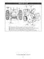
ENGtNE
DISCHARGE
CHUTE
O
ALL FLANGE
BEARINGS
O
ROLLER
CHAIN
GAGE
WHEEL
AUGER
GEAR
CASE
Q
Add Sears S.A.E. 10W oil (or equivalent)
O
Add Sears 5W-20
every 2 hours and after each use.
(_
Add Sears S.A.E. 30W oil {or equivafent) as required. Check before each use.
_)
Remove chute and coat with clinging type grease such as lubriplate once each season.
oil {or equivalent) as required. Check every 5 hours and before each use.
For Service
Helps Chart,
--13--
see page 27.
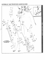
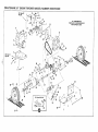
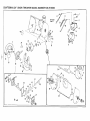
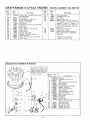
CRAFTSMAN
24"
SNOW
THROWER
MODEL
NUMBER
536,918300
14
211]
78
2
C
19
\
55
42
\
\
52
\
5O
11
Ref.
49
Item 4
2
53
_©
11
\
\
51
47
iTEMS
3O
ALL UNNUMBERED
ARE INTERCHANGEABLE
WITH OPPOSITE
SIDE
÷
_Q
I •
Ref, Item 38
Page 16
Ref. Item
Page 16
3
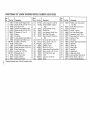
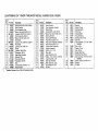
CRAFTSMAN
Key
No.
1
2
3
4
5
6
7
8
9
I0
11
12
13
14
15
16
17
18
19
20
Pa_ No.
49551
122052
49106
49569
122033
996407
25644
49576
49557
49558
9413447
50168
22822
443874
50607
997316
9417373
67194
68416
68413
*Standard
o1
I
Hardware
24"
SNOW
THROWER
Key
No.
Description
Cable, Impeller/Auger
Control
*Screw,
Hex Hd, 5/16-18
x 13,4 In.
Push Nut, 3/16
In.
Bracket,
Chute Deflector
Cable
*Screw,
Hex Hd, 5/16-18
x 13/8 rn.
*Fiatwasher,
5/16
In. I.D.
Spring
Hand Grip
Lever Assembly,
Chute Deflector
Bracket, Chute Deflector
Lever
Locknut,
5/16-18
Thd
Panel, Control
Knob, Wheel Drive Control Lever
*Screw,
Hex Hd, No. 10-24 xY_ In.
Knob, Control
Lever
Locknut,
No. 10-24 Thd
*FIatwasher,
No. 10
Decal, Chute Control
Decal, Craftsman
Decal,
Items
Control
- May
MODEL
PaneJ
Be Purchased
. ..I
Locally.
NUMBER
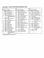
Pa_
No.
21
22
271166
50198
23
24
25
26
27
50197
25494
50393
50146
50152
28
29
30
31
32
33
34
35
36
37
38
9423771
122119
9413534
48395
455481
48400
120228
48399
23940
997319
23939
536.918300
Description
Locknut,
Keps, No. 10-24 Thd
Control Assembly,
Impeller/
Auger
Control Assembly,
Throttle
Shoulder
Bolt
Lever Assembly,
Wheel
Drive
Rod, Wheel Drive, Upper
Retainer
Bracket, Wheel
Drive
Rod
*Screw,
Hex Hd, No. 10-24 x 1/2in.
*Screw,
Hex Hd, 3/g-16 x 3,4 In.
Locknut,
3/8-16 Thd
Sprocket,
9 Tooth
*Roll Pin, 3/16 x 1 In.
Bracket, Lower Chute Control Rod
*Screw,
Hex Hd, 5/16-18
x % in_
Rod, Chute Control,
Lever
U-Bolt
Locknut,
No. 10-32 Thd
Spring
Key
No.
39
40
41
42
43
44
45
46
47
48
49
50
51
52
53
54
55
56
Part
No,
48402
180022
47323
9424215
48405
120638
122017
22O25
40631
48403
48441
49545
47422
48641
49544
49564
49008
133058
61817
Description
..........
Bracket,
Lower Chute Control
Rod, Rear
*Screw,
Hex Hd, 1A-20 x 1 In.
Pivot Block
Locknut,
_,4-20 Thd
Rod, Chute Control,
Upper
*Lockwasher,
Split, 5/16
Fn.
*Screw,
Hex Hd, 5/16-18
x 1 in.
Washer,
Formed
Nut, Retain
Bracket, Upper Chute Control Rod
Hand Grip
Handle, Left
Clamp, Cable
Hand Grip
Handle, Right
Cable, Power Clutch
Lever Assembly,
Power Clutch
*Screw,
Rd Hd, 1,4-20 x _,4 In.
Owner's.
Manual
(Not Illust.)
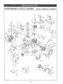
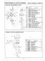
CRAFTSMAN
24"
SNOW
THROWER
MODEL
8
9
10
Ref.Item23
Page20
:'o
_
NUMBER
536.918300
13
ITEMS
ALL UNNUMBERED
ARE INTERCHANGEABLE
WITH OPPOSITE
SIDE
6
21
22
4
I
24
Ref. Item 3
Page 18
I
62
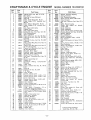
CRAFTSMAN
Key
No.
Pa_ No.
1
2
3
4
5
6
9413534
42619
49454
122119
68423
15316
7
8
48422
138538
9
10
!
_J
l
1I
12
13
t4
15
16
17
18
19
20
2t
35055
48424
41727
49577
49530
274517
40616
25177
48388
1O2883
27324
50158
50171
24"
SNOW
Description
Hardware
MODEL
,..
Key
No.
Locknut,
_/_-16 Thd
Screw, Taptite,
3/B-16 x Vz In.
Plate, Engine Mount
*Screw,
Hex Hd, 3/8-16 x 3,4 In.
Decal, Key, On/Off
Engine, Model No. 143.696102
(See Engine
Repair Parts List)
Spring
*Lockwasher,
Internal
Tooth,
5/16
In. I.D.
Screw, Taptite,
No. 10-24 x 1/2In.
Bracket,
Brake
Shoulder
Bolt
Pad, Brake
Belt Guide, Lower
*Flatwasher,
3/_ In. I.D.
Bearing,
ImpeIler
*Flatwasher,
3,4 In. I.D.
Pulley, Impeller/Auger
*Set Screw, 5/16-18
x 3¼ In.
Key, Hi-Pro, No. 606
Pulley, Transmission
Transmission,
Model No. 143.735
(See Transmission
Parts List)
*Standard
THROWER
Items
- May
Repair
Be Purchased
Locally.
NUMBER
Part
No.
22
23
24
25
26
27
28
29
30
31
32
33
34
35
36
37
38
39
40
50150
120380
181566
36625
50154
50170
50641
50640
20307
50542
50155
50149
996407
120638
180087
50153
50169
41891
138485
41
42
43
41890
25072
48666
536.918300
Descrip,tion
..........
Gear, M;ter Drive
*Lockwasher,
Split, % In. I.D.
*Screw,
Hex Hd, 1A-28 x 3,4 In.
Ring, Retaining
Washer,
Thrust
Side Frame Assembly,
Roller Chain Assembly
Roller Chain Assembly
Link, Connector
Sprocket
& Bearing
Shaft, Intermediate
Right
Assembly
Spacer
*F}atwasher,
5/16
In. I.D.
*Lockwasher,
Spilt, 5/16
In. I.D.
Screw,
Hex Hd, 5/t6-18
x 2 In.
Washer,
Thrust
Side Frame Assembly,
Left
Washer,
Bow
*Lockwasher,
Externaf
Tooth,
5/16
In. I.D.
Shoulder
Bolt
Disc, Bearing
Retainer
Bearing,
Self-Aligning
Key
No.
Pa_
No.
44
45
46
47
48
49
50
51
52
53
9424215
48445
169
9413447
20712
180075
41709
36602
50624
35498
54
50163
55
56
57
58
59
60
50148
454512
50151
39024
50147
35144
61
62
50166
50164
Description
....
Locknut,
V_-20 Thd
Wheel & Tire Assembly
*Screw,
Hex Hd, 5/! 6-18 x 1% In.
Locknut,
5/16-18
Thd
Chains, Snow {Set of Two)
*Screw,
Hex Hd, 5/16-18
x % In.
Spacer
*Bolt, Carriage,
1,4-20 x % In.
Axle & Sprocket
Assembly
Screw,
Hex Washer
Hd Tap,
5/16-18
x 3/_ In.
Plate Assembly,
Transmission
Mounting
Bearing,
Flanged
Pin, Spring, 3/16
x 3,4 In.
Gear Miter Driver
Flat-washer,
1/2 In. I.D.
Rod, Wheel Drive, Lower
Screw,
Hex Hd Slotted Taptite,
No. 10-24 x _/_ In.
Cover, Bottom
Cover, Rear
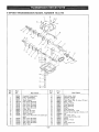
CRAFTSMAN
Ref. Item
Page 114
24"" SNOW
THROWER
MODEL
NUMBER
536.918300
22
ALL UNNUMBERED
ITEMS INTERCHANGEABLE
WITH OPPOSITE
SIDE
3
2
Ref, Item 2
Page 16
I
L
Ref, Item 3
Page 14
Ref. Item
19
50
51 \
55 _
49
45
58
57
Ref. item 23
Page 20
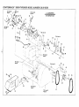
CRAFTSMAN
Key
No.
L
c.O
F
Part
No.
t
2
3
4
159920
138479
41652
49012
7
271166
120228
180016
8
9
10
11
120380
9424215
48994
t 20394
12
40886
13
49018
14
15
16
17
18
19
49527
49010
49531
456836
49014
48991
*Standard
Hardware
24-
SNOW
THROWER
Key
No.
Description
Screw, No. 10-24 × 1/2 In.
Lockwasher,
External Tooth
Clip, Wire
Bracket, Impel[er/Auger
Cable
Nut, Keps,
*Screw,
Hex No_
Hd, I0-24
5/16-18Thd x % In.
Screw, Hex Hd, _,4-20 x 1/2 In.
Lockwasher,
Split
Locknut,
1,4-20 Thd
Plate, Idler Mount
Washer
Screw, Taptite,
Hex Washer
_A-20 x 3,/8In.
Brace
Spring,
Idler
Arm, Wheel
Drive
Spacer
Pin, 1/_ x 21/_ In.
Clevis Pin
Bracket,
Power Clutch
Items
MODEL
Hd,
Cable
- May Be Purchased
Locally.
2O
21
22
23
24
25
26
27
28
29
30
31
32
33
34
35
36
37
38
39
NUMBER
536.918300
Key
Part No.
121223
49019
24347
49OO9
49016
49017
36285
48140
138557
46376
47410
45892
49504
50610
120382
124829
3140
46511
120918
49505
Description
No.
Cotter Pin, 1/16
Selector
Assy
Spring
Arm, Impeller/Auger
Bracket,
Mounting
Plate
x 3/_ In.
Drive
Key, Ignition
Locknut (Switch
Part)
Lockwasher
(Switch
Part)
Switch (Incl. Items 26, 27 & 28)
Wire Assembfy,
Ignition
Carriage
Bolt, 3/8-16 x tl/2 In.
Idler Arm, Primary
Pulley, Idler
Lockwasher,
Split 3/8 In,
Nut, Hex Jam, 3/8-16 Thd
Washer,
Wave
Bolt, Shoulder
Screw,
Hex Hd, %-16 x 11/2 In.
Idler
Arm,
Auger
40
41
42
43
44
45
46
47
48
49
50
51
52
53
54
55
56
57
58
Pa_
No.
50608
9413534
41727
138538
41728
49581
26794
44917
998503
120741
120638
49822
49570
48999
9413447
35144
46161
48534
68415
Description
Roller Arm Assembly
*Locknut,
3/8-16 Thd
Bolt Shoulder
Lockwasher,
Internal
Tooth
Spacer
V-Belt
Key, Square,
_/_x 1 I/2 in.
Pulley, Engine
*Set Screw,
5/16-18
x 1,4 In.
*Screw,
Hex Hd, 5/16-24
x 3,/4In.
*Lockwasher,
Split, 5/16
f.D.
Belt Guide, LH.
V-Belt
Mounting
Bracket Auxiliary
*Locknut,
5/16-18
Thd
Screw,
Stotted Hex Hd, Taptite,
10-24 x 3/8 In.
Extension,
Belt Cover
Cover, Belt
Decal
CRAFTSMAN
24"
SNOW
THROWER
MODEL
NUMBER
536.918300
_ J
/
<-
Ref. Item
Page 14
8
--I
1
17
9
?
24
/
3O
CRAFTSMAN
No,
I
Pa_ No.
1
2
3
4
5
6
49573
67173
49560
120834
9413447
49550
9
10
11
12
13
14
15
16
17
18
19
20
21
180016
47240
9424215
49555
997316
49552
9413534
274517
27318
39119
271184
446363
25091
126358
6768O
24"
SNOW
THROWER
Description
Screw, Hex Hd, No' 10-24 x 5/8 In.
Decal, Caution
Chute Assembly, Top
*Screw, Hex Hd, 5/16-18 x ¾ In.
Locknut, 5/16-18 Thd, Type N
Chute Assembly, Bottom
*Screw, Hex Hd, _-20 x ½ In.
Chute Clip
Locknut, Hex, _-20 Thd, Type N
Chute Rod
Locknut, No. 10-24 Thd
Spring
Locknut, 3/8-16 Thd
*Flatwasher, 3/8 ID
Gage Wheel Assembly
Shoulder Bolt
*Nut, Keps, 5/16-18
*Flatwasher, 5/16 tD
Skid
Carriage Bolt, 5/16-18 x 1 In.
Decal, Caution
*Standard Hardware Items - May Be Purchased Locally.
MODEL
NUMBER
Key
No.
Part No.
22
23
24
25
26
27
28
29
30
31
32
33
34
35
36
37
38
39
40
41
42
68183
47238
67167
36602
180077
48209
48210
48216
48459
48217
48606
47256
454565
13322
48768
21970
48767
48264
48352
3021
24274
536.918300
Description
Decal, Caution
Cover Assembly, Impeller
Decal, Name
Carriage Bolt, ¼-20 x 5/8 In.
*Screw, Hex Hd, 5/16-18 x ¾ In.
Bearing, Retainer
Bearing, Self-Aligning
Auger Housing End, R.H.
Auger Cover & Scraper Assembly
Auger Housing End, L.H.
Impeller Shaft, Assembly
Impeller Assembly
Roll Pin, _ x 1¼ In.
Shear Bolt
Auger Assembly, R.H.
*Washer, 1 tD x % OD x .125 Thk
Auger Assembly, L.H.
Gear Case Assembly
Shaft, Gear Box, Long
*Key, Woodruff, No. 9
Oil Seal
Key
No.
Pan No.
43
44
45
46
47
48
49
50
51
46274
48275
32397
47787
21682
21681
48273
23700
48265
52
53
54
55
56
57
21684
48271
47801
48279
48272
48266
58
59
60
35498
48269
21922
Description
Bearing
Washer, Thrust
Bearing, Needle
Worm Gear
Spring Washer
Ring, Retaining
Bearing, Input, Front
Pipe Plug
Gear Case Assy, L.H. (Incl. Items
59 & 60)
*Key, Hi-Pro
Washer, Thrust
Gear, Bronze
Gasket, Gear Case
Shaft, Gear Box, Short
Gear Case Assy, R.H. (Incl. Items
59 & 60)
Screw, Taptite, 5/16-18 x _ In.
Bearing
Oil Seal
CRAFTSMAN
4-CYCLE
ENGINE
MODEl.NUMBER143.696102
2
72
124
169
--22--
CRAFTSMAN
Ref.
No.
Part
No.
1
2
3
4
5
5
32586B
27652
27642
32630
32783
32784
6
6
27878A
27880A
7
8
9
11
12
13
t4
14
27882
27881
32581
32680A
29783
27884
335928
33593B
14
33594B
14
34517
t4
34518
14
34519
15
15
15
16
17
32595
32596
32597
27888
3259IC
18
19
2t
650662A
34242
32115
22
23
34034
31303B
24
25
25A
25B
26
28
29
30
3t
32
33
34
35
36
37
28427
34011A
3359O
33893A
"30684
650488
650493
610118
650489
"32631
30938A
30939A
650697A
65069f
33636
37
34251
Canada
38
39
40
41
43
44
45
46
48
49
50
52
"27896
28423
28424
28425
650128
27627
*27915
30195A
30196
30969
32678
32326A
4-CYCLE
ENGINE
Part Name
Ref.
No.
Cylinder Assy. (Incl. Nos. 2, 3 Et 4)
Pin, Dowel
Plug, Sq. hd. pipe (Oil drain)
Seat, Oil
Valve, Intake (Std.) (Incl. No. 9)
Valve,
Intake {1/32" oversize)
(Incl.
No. 9)
Valve, Exhaust IStd.) (Incl. No. 9)
Valve, Exhaust (1/32" oversize) (Incl.
No. 9)
Cap, Upper valve spring
Spring, Valve
Cap, Lower valve spring
Crankshaft Assy. (Incl. Nos. t2 8- t3)
Pin, Crankshaft gear
Gear, Crankshaft
Piston _t Pin Assy. (Incl. No. 16) (Std.)
Piston 8- Pin Assy. (Incl. No. 16) (.010
oversize)
Piston 8- Pin Assy. (incl. No. 16) (.020
oversize)
Piston, Pin 8 Ring Assy. (Inct. Nos. 15
8 16){Std.)
Piston, Pin 8 Ring Assy. (Incl. Nos. 15
8- t6) (.010 oversize)
Piston, Pin 8 Ring Assy. (Incl. Nos. 15
8- 16) (.020 oversize)
Ring Set, Piston (Std.)
Ring Set, Piston (.0t0 ov_ersize)
Ring Set, Piston (.020 oversize)
Ring, Piston pin retaining
Rod Assy., Connecting
(Incl. Nos. t8
8 19)
Screw, Connecting
rod
Dipper, Oil
Camshaft
{Mect}.
Compression
Release)
Lifter, Valve
Cover, Cytinder (Incl. Nos. 24, t06 _
147)
Seat, Oil
Dipstick, Oil (Incl. No. 25A)
"O" Ring
Tube, Oil filler
Gasket, Cylinder cover
Screw, Hex hd. Seres, i/4-20 x 1-1/4
Screw, Hex hd. Senqs, t/4 20 x 1 3/4
Cover, Spark plug
Screw, Hex hd. Seres, 1/4-20 x 5/8
Gasket, Cylinder head
Head, Cylinder
Cover, Cylinder head
Screw, Hex flange hd., 5/16-18 x2 1/2
Washer, Flat
Plug,
Spark
(Champion
J-8
or
equivalent)
Exc_
for Canada
Resistor Spark Plug {Canadian Regulations require RJ-17LM
resistor spark
plug)
Gasket, Valve spring cover
Body Assy., Breather
Element, Breather
Cover, Valve spring
Screw, Fil, hd. Seres, t0-24 x 1/2
Tube, Breather
Gasket, Intake
Flange, Carburetor (Incl. Nos. 77 E:t80)
Screw, Fil. hd. Seres, 5/t6 18 x 3/4
Cap, Oil drain
Nippie, Pipe
Lever, Governor
--23--
MODEL
P_t
No.
55
56
57
61
62
63
3O2O5
30826
30824
650494
30700
30699C
64
65
29536
650561
66
67
69
70
71
72
75
76
77
78
34374
34170
29747A
32158B
650490
8116
231688
29752
27793
28942
80
83
84
85
89
91
93
94
95
96
97
98
650572
29642
29826
29216
31291
34585
650764
32398
28820
34581
650257
650765
99
100
101
102
103
104
105
106
t07
!08
109
t10
11I
112
1t3
650760
29538
26073
*2793O
32401
650694A
30196
31845
30591
29193
30588A
30590A
34159
34158
650561
114
115
1t7
118
119
34186
30998B
26460
30962
650665
120
12I
124
125
I26
127
129
130
131
650128
3O622
29716
34129
34133
34144
32589
31843A
28763
132
650548
NUMBER
143.696102
!
P_tName
Bracket, Governor adjusting
Spring, Extension
Link, Governor4o-throttle
Screw, Fil. hal. Seres, 6-40 x 5/16
Yoke, Governor
Rod Assy. Governor (Incl. Nos. 61 8
62)
Baffle, BIower housing
Screw,
Hex
washer
hal.
durlock,
1/4-20 x 5/8
Decal, Instruction
Decal, Instruction
Screw, Hex hd. Sems, 5/16-24 x 3/4
Housing, Blower (Ind. Nos. 135 8 136)
Washer, 8elleville
Nut, Crankshaft
Gasket, Carburetor
Nut 8r Lockwasher
Assy., 1/4-28
Clip, Conduit
Screw, Hex washer hd. Seres, 10-32 x
3/8
Screw, Fiat hd. Seres, 1/4-28 x 1-1/8
Ring, Retaining
Screw, Hex washer hd., 10-32 x 3/4
Locknut,
Hex, 10-32
Plug, Cover
Knob, Control
Nut, "U" Type
Bracket, Carburetor
cover
Screw, Fil. hd. Seres, 10-32 x 1/2
Cover, Carburetor
Screw, Pan hd. Sems, 8-32 x 5/16
Screw,
Hex washer hd. seff-drillin9,
10-32 x 1/2
Screw, Pan hd. taptite, 8-32 x 7/16
Base, Engine mounting
Washer, Flat
Gasket. Muffler
Muffler
Screw, Hex flange hd., 5/16-18 x 2
Screw, Fil. hd., 5/16-18 x 3/4
Shaft, Mechanical
governor
Gear Assy., Governor (Incl. No. t10)
Ring, Retaining
Spool, Governor
Washer, Flat
Plate, Fuel tank mounting
Bracket, Fuel tank mounting
Screw,
Hex
washer
hd.
durlock,
t/4-20 x 5/8
Tank Assy., Fuel (Incl. No. 115)
Cap, Fuel
Clamp, Fuel line
Line, Fuel
Screw,
Hex washer hd. Seres, selftap, 1/4-t4 x 7/8
Screw, Fii. hd. Seres, 10 24 x 1/2
Extension, Blower housing
Screw, Pan hd. Seres, 1/4-28 x 7/16
Decat, Warning
Decal, Choke
Decal, "Primer"
Key, Flywheel
Bracket, Governor gear
Screw, Hex washer hd., shakeproof,
10-32 x 19/32
Screw, Hex washer hd., 8-32 x 5/16
*Indicates Parts Included in
Gasket Set, Ref. No. t69.
CRAFTSMAN
Ref.
No.
134
134A
t35
t36
t37
138
139
140
141
144
145
146
147
148
!49
150
152
4-CYCLE
ENGINE
Part
Ref.
Part Name
No.
No.
33io8AControl
6! 0973
650736
33013
32312
32180A
32182
32183
32184
650542
33876
34240
31546
34126
28545
650643
34127
MAGNETO
MODELNUMBER143.696102
Assy.,
Remote
speed (incl.
Nos. 56 8- 134A)
Terminal Assy.
Screw, Pan hd., 10-t6 x 3/8
Cover, Starter bubble
Retainer, Primer bulb
Line, Primer
Primer Asy. (Incl. Nos. 137, 140 8-141)
Bulb, Primer
Body, Primer
Screw, Hex hd., 5/16-18 x 3/4
Gasket, Stator
Wire, Ground
Bushing, Crankshaft
Bracket, Grommet mounting
Grommet,
Plastic
Screw, Pan hd. self-tap, 8-18 x 3/8
Guard, Starter
NUMBER
Part
i
No,
32576
29918
32125
590417
610694A
154
t62
163
164
166
167
168
169
170
631920
590473
33239
"Indicates
Parts Included in
Gasket Set, Ref. No. 169.
610694A
f_lA
available as an assembly. The
magneto number is shown for
reference purposes only. O_der
The complete magneto is not l
Ref.
No.
_
3__'"_J
Part Name
seal, Snow guard
Lockwasher,
No. 8 E.T.
Cup, Starter
Screen, Starter cup
Magneto
(The complete
magneto
is
not available
as an assembly.
The
magneto
number
is shown
for
reference purposes only. Order corn
ponent parts individually,
as shown in
parts list.)
Carburetor
(Incl. No, 75)
Starter Assy., Rewind
Gasket Set (Incl. items marked *)
Electric Starter Kit No. 143.88902
(Optional)
No.
610694A
1
30811A
1A 610934
2
30551
3
610947
4
30992
5
30547A
6
610385
7
33356
8
61O408
9
29181
10
610593
11
30560A
12
30554
13
305488
14
30545
15
30561B
13_
1
16
17
18
19
19
8\
--24--
30549
31311
29629
610955
61O956
Parg Name
Magneto
Flywheel
(Incl. No. IA}
Fan
Spring, Breaker box dust cover
Cover, Dust
Cam, Breaker
Contact Assembly,
Breaker
Washer, Terminal
Tab, Ground terminal
Nut, Terminal
Screw & Washer, Breaker
Screw, Condenser
Coif Assy. (Incf. No. 12)
Wire, Lead
Condenser
Core & Plate
Stator
Assy, (Incl. Nos. 2, 3,
thru 14 & 16thru
19)
Felt, Cam wiper
Clip, Coif locking
Spring, Coi{ wedge
Gasket, Dust cover
Gasket, Dust cover
5
CRAFTSMAN
4-CYCLE
CARBURETOR
NUMBER
ENGINE
MODELNUMBER143.696102
631920
"
% 2%
, /
Ref.
No.
14
15
t
|
|
------ 16
I
I
5
24
/
,,
11
,
8
I
@=
23----_ ,_
8_
--22
30----_ i
"'-.
I3
1
Part
No.
1
2
3
4
5
6
7
8
9
10
11
12
631920
31834
632016
631036
650506
630766
650417
631913
630739
631815
*630748
*631O27
*631021
13
14
t5
16
21
22
631022
632019
*631024
631867
27110
*31839
23
24
25
26
30
31
32
*630740
*631078
*631028
6318O3
630738
630735
31840
Part
Nmne
Carbu retor
......
Shaft & Lever Assy., Throttle
Spring, Throttle return
Shutter, Throttle
Screw, 4-40 x 3/t6
Spring, Idle regulating screw
Screw, Idle regulating
Shaft & Lever Assy., Choke
Washer, Flat
Shutter, Choke
Plug, Welch
Plug, Welch
Inter Needle, Seat & Clip Assy.
(Incl. No. 13)
Clip, Inlet needle
Float, Carburetor
Shaft, Float
Bowl, Float
Gasket, Bowl-to-body
Adjustment Screw Assy., Main
(Incl. Nos. 8, 21, 23 & 30)
"O" Ring, Adjustment screw
Screw, Idle adjustment
Gasket, Bowl-to-body
Fitting, Fuel inlet
Spring, Main Adjustment screw
Spring, Choke stop
Repair Kit (Incl. items marked *)
32
REWIND
STARTER
NUMBER
590473
iRef.
No.
//%
I
2
3
4
5
6
7
8
9
10
11
12
13
,.,_.
3_D
Q_12
--25--
Part
No.
i 590473
590409A
590474
590411
590148
59O475
590478
590414
590415
590451_
590387
590459
590476
590477
Part
Name
Starter, Rewind
Screw, Retainer
Cam, Dog
Spring, Brake
Dog, Starter
Spring, Dog
Pulley
Spring & Keeper Assy.
Housing Assy., Starter (I ncl. No. 1 )
Rope, Starter
Handle Assy., Starter
Pin, Centering
Retainer, Dog
Screw, No. 6 x 5/16
5 SPEED
Ref.
No.
TRANSMISSION
Part
No.
1
2
3
4
5
6
7
8
9
lO
11
12
13
794254
770061
772070
776161
77812lA
778122
778123
778124
778125
784266
786060
786061
776134
778109
t4
15
16
t7
18
778126
778127
778128
778129
776143
MODEL
NUMBER
Ref.
No.
Part Name
Complete Transmission
Case, Transmission
Cover, Transmission
Shaft, Output
Gear, Spur 120 teeth)
Gear, Spur {22 teeth)
Gear, Spur (25 teeth)
Gear, Spur (30 teeth)
Gear, Spur (35 teeth)
Collar, Shift
Sprocket (14 teeth)
Sprocket (!0 teeth)
Shaft, Counter
Gear, Bevel (42 teeth 8- 15 tooth
gear)
Gear, Spur (20 teeth)
Gear, Spur 125 teeth)
Gear, Spur (28 teeth)
Gear, Spur (30 teeth)
Shaft, Input
spur
--26 d
19
20
27
28
29
30
3I
32
33
34
35
36
37
40
4t
42
43
44
45
46
143.735
Part
No.
778113
786049
780105
786062
780072
780086
792072
792035
780109
788040
784267
792073
792089A
792077
792078
792079
780108
792074
792001
788054
Part Name
Bevel pinion, Input
Sprocket (8 teeth)
Bushing,
Flanged
Chain, Roller (No. 41 chain, 22 links)
Race, Thrust
Bearing, Needle
Ring, Retaining
Ring, Retaining
Washer
Ring, Retaining
Rod 8 Fork Assy., Shift
Screw, Hex hal. tap-tire, 1/4-20 x !-!/4
Key
Ball, Steel, 5tt6
Screw, Set, 3/8-16 x 3/8
Spring
Washer, Thrust
Plug
Ring, Square cut
Gasket
TROUBLE
Difficult
Engine
starting,
runs
erratic
LOOK
Defective
spark
I_locked
empty
FOR
plug
Loss
Engine
stalls;
Unit
of power;
runs
erratic
Replace
fue'i 'iine or
Clean
running
impeller
paragraph
on CHOKE
Obstruction
Water
line;
plug,
check
fuel
supply.
vibration
Loose parts;
Damaged
impeller
Unit fails
itself
to propel
Drive belt loose
defective
Drive
shear
roller
to RUN position.
Do
not
remove
to drain
carburetor
bowl
fuel
or
bolt
chain
when
belt
to Roller Chain Replacement
section of this manual.
Adjust
unit drive belt; replace if defective.
Refer to Drive Belt
Adjustment
paragraph
in Adjustment
section or Drive Belt
Replacement
paragraph
in Maintenance
section of this manual.
loose
Adjust
impeller!auger
drive belt; replace if defective.
Refer to
Drive Belt Adjustment
paragraph
in Adjustment
section or
Drive Belt Replacement
paragraph
in Maintenance
section of
this manual,
Replace shear
in Maintenance
bolt broken
clogged
lodged
in auger
Auger
Transmission
trouble
trouble
Refer to Impeller/Auger
in Adjustment
section
bolt. Refer to Shear Bolt Replacement
section
of this manual.
of
paragraph
Clean discharge
chute and inside of auger housing.
Refer to
Danger after Step 6 of Snow Thrower
Operation
paragraph
in
Operation
section of this manual.
Remove
Thrower
manual,
gear case
hot.
paragraph
Shear
object
is
Replace shear bolt. Refer to Shear Bolt Replacement
in Maintenance
section of this manual.
Adjust
impeller/auger
control cable.
Control
Cable Adjustment
paragraph
this manual,
Foreign
engine
paragraph
Impeller!Auger
control
out of adjustment
chute
the
Replace drive belt. Refer to Drive Belt Replacement
in Maintenance
section of this manual.
Replace roller chain. Refer
paragraph
in Maintenance
Unit drive b'e'li loose
or defective
Discharge
tank.
Stop engine immediately;
tighten
all bolts and make all
necessary
repairs.
If vibration
continues,
have the unit serviced
by a competent
repairman,
defective
Impeller
drive
or defective
lever
Remove carburetor
bowl
Refill with fresh fuel
system
Excessive
Broken
Engine.
Remove obstruction;
clean impeller
housing.
Refer to Danger
after Step 6 of Snow Thrower
Operation
paragraph
in
Operation
section of this manual.
housing
in fuel
To Start
Set choke
in
CAUTION:
Unit fails to
discharge snow
defective
fuel
gas tank
Review
"-Engine
REMEDY
object
from auger.
Operation
Refer to Danger
paragraph
in Operation
after Step 6 of Snow
section
of this
Check auger gear case for broken or bound parts and for oil level.
See Unit Repair Parts section of this manual for correct order of
parts.
Have transmission
--27L
checked
by competent
repairman.
HOW TO ORDER
owner's
manual
REPAIR
PARTS
The Model Number will be found on a plate attached to the
main frame. Always mention the Model Number when requesting
service or repair parts for your CRAFTSMAN
SNOW THROWER.
All parts listed herein may be ordered through SEARS, ROEBUCK AND CO. or SIMPSON-SEARS
LIMITED Retail or
Catalog Stores. If the parts you need are not stocked locally,
your order will be electronically
transmitted
to a SEARS
Repair Parts Distribution
Center for expedited handling.
WHEN ORDERING
REPAIR
FOLLOWING
INFORMATION
PARTS, ALWAYS
GIVE THE
AS SHOWN tN THIS LIST:
1. The PART NUMBER
2. The PART DESCRIPTION
MODEL NO.
536.918300
SEARS
SERVICE
is at
YOUR
SERVICE
SEARS,
Part No. 61817
ROEBUCK
3. The MODEL
NUMBER
- 536.918300
4. The NAME OF ITEM - Snow
5. The ENGINE MODEL
Thrower
NUMBER
- 143.696102
"Your Sears merchandise has added value when you consider
that Sears has service units nationwide staffed with Sears
trained technicians . . . professional technicians specifically
trained on Sears products, having the parts, tools and equipment to insure that we meet our pledge to you.., we service
what we sell."
AND
CO., Chicago,
1879
illinois
60684
1
U.S.A.
Printed
in U S.A.