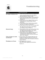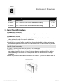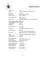
1
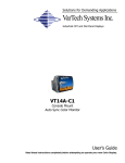
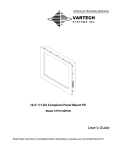
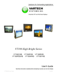
Solutions for Demanding Applications
VarTech Systems Inc.
Industrial CRT and Flat Panel Displays
VT190 ColorVue Series
19.0” Flat Panel Series LCD Monitors
VT190PC
VT190RC
User’s Guide
Read these instructions completely before attempting to operate your new Color Display.
VT190 ColorVue User Guide
150-077
Table Of Contents
Section
Page
Section
Page
Section 1
Section 5
Introduction
Touch screen
14
1.1 About LCD Monitors
1
5.1 Introduction
14
1.2 Product Safety Precautions
2
5.2 Installation
14
Section 2
Section 6
Display Setup
Troubleshooting Tips
2.1 Display Features
3
2.2 Unpacking The Display
4
Section 7
2.3 Included Parts
4
Cleaning & Maintenance
2.4 Connecting Your Display
4
2.5 Signal Connections
4-6
15
16
Section 8
Mechanical Drawings
17
Section 3
Panel Mount Mechanical Drawings
18-19
Getting Started
Rack Mount Mechanical Drawings
20
3.1 Adjusting the Display
7
3.2 Control Panel Functions
7
3.3 OSD Adjustment
8-12
Section 4
Display Timing
13
Section 9
Display Specifications
21
Section
1
1.1
INTRODUCTION
About LCD Monitors
What you gain by using an LCD monitor in your industrial controls
LCDs
are the future of display technology. Although CRTS have dropped in
cost significantly, they do not offer the performance, reliability, and
mounting options available with LCDs. LCD monitors consist primarily of
an LCD, Video Board and a Back Light video. The LCD determines to a
large extent the viewing angle, brightness and contrast. Beyond that it is
the function of the video board which converts the analog RGB (Red, Green, Blue) signals from a
standard video card to a high quality, digital RGB that the LCD can display.
Recently the video card has taken on a new role. It is the responsibility of this device to “scale” a
particular video resolution to the “native” resolution of the LCD. Simply, consider that a computer is
putting out a VGA [640x480] resolution signal, yet the LCD that is connected is an XGA
[1024x768] display. The displayed picture would be in the center 1/3 of the LCD. With the
introduction of the scaling engine. The converter will mathematically recalculate the 640x480 to
1024x768. This may sound simple but it is in fact a complex algorithm that adjusts for different
aspect ratios and pixel alignment, essentially smoothing text and graphics to produce a picture
that is pleasant to the eye.
All Vartech displays from 12.1” (800x600) to 23.1 (1600x1200) incorporate scaling engines in the
converter card.
1
VT190 ColorVue User Guide
150-077
1.1
Product Safety Precautions
⇒
Ensure that sufficient space is available around the display to provide the circulation
necessary for cooling.
⇒
Ensure that the ambient air temperature will not exceed the specified maximum
temperature.
⇒
Do not attempt to service this display yourself. The rear chassis has a seal so that non
qualified personal will not expose themselves to dangerous voltages or other risks.
⇒
To protect from electrical shock, unplug the display power supply from the wall before
moving.
⇒
Do not expose the display to direct sunlight or heat.
⇒
Do not use this display near water
⇒
Do not place any heavy objects on the power cords. Damage may cause electrical shock.
⇒
Unplug the power supply from the wall or unit if one of the following conditions exists.
⇒ Power cord or plug is damaged or frayed
⇒ Liquid is spilled into the display or the display is exposed to rain or water.
⇒ The display does not operate normally when the operating instructions are
followed.
⇒ The display has been dropped or the enclosure has been damaged.
⇒ The display exhibits a distinct change in performance, indicating a need for
service.
2
Section
DISPLAY SETUP
2
2.1 VT190 ColorVue Series Display Features
⇒
Capable of displaying unlimited colors in a continuous spectrum. The high contrast LCD
enhances the image with no geometric distortion.
⇒
The VT190 ColorVue Series directly accepts an analog 5 wire RGB with separate H/V sync.
⇒
The VT190 ColorVue Series is auto synchronous adjusting the display to the appropriate input
between VGA, SVGA,XGA, and SXGA.
⇒
The VT190 ColorVue Series is available in Panel Mount, Rack Mount, or Wall Mount industrial
packages.
⇒
The VT190 ColorVue Series is supplied with a Anti-Reflective Screen unless equipped with an
optional Touch System.
⇒
The VT190 ColorVue Series has an integrated 115/220VAC supply as standard on all models.
3
VT190 ColorVue User Guide
150-077
2.2 Unpacking and setting up your display
Your LCD monitor package will consist of the components listed below. Open shipping
container and lay all components on a flat clean surface.
2.3 What is included with your display
⇒
⇒
⇒
⇒
⇒
⇒
VT190RC or VT190PC LCD Monitor
5 ft Video Cable
10-32 Mounting Hardware. (For use with Panel Mount only)
6 ft RS232 Touch Interface Cable (Optional when touch is installed)
CD ROM with Touch Screen Drivers (Optional when touch is installed)
Users Guide (Printed or on CD)
2.4 Connecting the Display
1. Connect all cables to the computer first. This would include the VGA cable and the optional
RS 232 serial touch screen connection.
2. After connecting the cables between the LCD monitor and the computer, plug the power
cord into the 115/220VAC power outlet.
3. Once the 115/220VAC connection is made, the display is active.
4. If your computer was off, turn on your computer.
5. Your display should now operate as a normal computer display showing your windows or
whatever video is being sent to the flat panel.
Note: If for any reason the display goes blank and gives an “out of Range” or “No Input Signal”,
your computer or video source is putting out a signal that is out of range of the LCD’s video
board. If this happens, reboot the computer or video source and make sure you are inputting
the correct signal. If the display doesn’t work properly, it may be because:
(a) The resolution is to high or low for the LCD.
(b) The refresh rate is set to high. Refresh on an LCD is different than a CRT. Set the refresh to
60Hz. CRT’s need a high refresh rate to avoid flicker. The refresh rate has no impact on
LCD’s.
(c) The power source is incorrect.
(d) The unit is malfunctioning. If you believe this to be true, disconnect the video cable from the
rear of the LCD and connect to a known good computer CRT display. If the computer
display is working satisfactory and the video is within the appropriate range, then contact
Vartech Customer service for a RMA number at 800-223-8050.
2.5
Signal Connections
To avoid irregular operation and /or damage to the display, please insure correct video is being
supplied as shown on the following page.
4
2.5
Signal Connections Cont.
You can use an HD-15 connector cable or a BNC adapter cable to connect the flat
panel monitor to the host computer. The HD-15 video cable (supplied in the kit) you
use with this monitor is equipped with a conventional HD-15 connector at each end.
Note: The following figure is the view looking into the pin end of the male connector or
solder term end of the female connector.
HD-15 Video Connector
The following table provides the pin numbers and
corresponding pin assignments for the HD-15 video
connector.
Pin Signal (HD15)
Pin Signal (HD15)
Pin
Signal (HD15)
1
Red Video
6
Red Video Ground
11
Monitor Ground
2
Green Video
7
Green Video Ground
12
DDC data
3
Blue Video
8
Blue Video Ground
13
Horizontal Sync
4
Not Used
9
+5 V
14
Vertical Sync
5
Ground
10 PC detection
15
DDC clock
DVI-I Connector (Digital / Analog)
C2
C1
C5
1
8
9
16
24
17
Pin Signal (DVI-I)
C3
C4
Pin Signal (DVI-I)
Pin
Signal (DVI-I)
C1
Not Used
C2
Not Used
C3
Not Used
C4
Not Used
C5
Not Used
Pin Signal (DVI-I)
1
T.M.D.S. Data2-
9
T.M.D.S. Data1-
17 T.M.D.S. Data0-
2
T.M.D.S. Data2+
10
T.M.D.S. Data1+
18 T.M.D.S. Data0+
3
SGND
11
SGND
19 SGND
4
Not used
12
Not used
20 Not used
5
Not used
13
Not used
21 Not used
6
DDC Clock
14
DDC Power
22 SGND
7
DDC Data
15
Ground
23 T.M.D.S. Clock+
8
Not used
16
Hot Plug Detect
24 T.M.D.S. Clock-
5
VT190 ColorVue User Guide
150-077
2.5
Signal Connections Cont.
Optional BNC Adaptor Cable
An HD-15 to 5-BNC adapter cable is available. The functions of the cables are
described below.
⇒ R, B, and G: Red, Green, and Blue input connectors to establish color.
These are used for RS-343 analog signals.
⇒ HS: Separate horizontal sync signal from the video source.
⇒ VS: Separate vertical sync signal from the video source.
6
Section
3
3.1
Getting Started
Adjusting the display
The VT190 Series display has an embedded microprocessor in the converter card.
Once you have the unit displaying the resolution you desire for your application do
the following:
In order to navigate to the appropriate adjustments, press Menu and the OSD layout
chart will appear as indicated in Fig. 1 from left to right.
If you press the “MENU” the new settings are saved and the OSM appear and your
setting will be stored in the unit’s non volatile memory.
1
3.2
2
3
4
Control Panel Functions
Control
1
Function
Use this button to turn the monitor on
and off.
POWER
2
MENU
Use this button to enter or exit the
On Screen Display.
3
SEL
Use this button to enter a selection in
the On Screen Display.
Use these button to choose or adjust
items in the On Screen Display.
4
7
VT190 ColorVue User Guide
150-077
3.3
On Screen Display (OSD) Control Adjustment
Screen Adjustment Operation Procedure
1) Entering the Screen Adjustment
The setting switches are normally at stand-by. Push the MENU button once to display the main menu of the screen adjustment. The adjustable items will be displayed in the main menu.
2) Entering the Settings
Use the Adjust ▼and Adjust ▲buttons to select the desired setting icon and push
the SELECT button to enter sub-menu.
3) Change the Settings
After the sub-menu appears, use the Adjust ▼and Adjust ▲buttons to change the
setting values.
4) Save
After completing the adjustment, push the SELECT button to save the setting.
5) Return & Exit the Main Menu
Exit the screen adjustment, push the ‘SELECT’ button and the ‘EXIT’ of “MISC
MENU”. When no operation is done around 60 sec (default OSD timeout), it goes
back t the stand-by mode and no more switching is accepted except MENU to
restart the setting.
8
3.3
On Screen Display (OSD) Control Adjustment Cont.
The following table indicates all the On Screen Display control, adjustment,
and setting menus.
Main Menu
Sub Menu
BRIGHTNESS
BRIGHTNESS
CONTRAST
CONTRAST
COLOR
PRESET
A
D
Reference
To adjust the brightness and contrast of
the screen
To customize the color of the screen
9300K
6500K
R/G/B (User Color)
POSITION
To adjust the position of the screen
V POSITION
H POSITION
TRACKING
CLOCK
To improve the clarity and stability of the
screen
PHASE
SETUP
AUTO CONFIG
To customize the screen status for a
user’s operating environment
INPUT
INFORMATION
RECALL
AUDIO
OSD ADJUST
EXIT
To Exit the OSD
EXIT
Legend
: Adjustable
A: Analog Input
D-SUB
D: Digital Input
DVI-D
9
VT190 ColorVue User Guide
150-077
3.3
On Screen Display (OSD) Control Adjustment Cont.
The OSD main menu is displayed on screen
when MENU key is pressed. The OSD menu
is a combination of graphic and text display.
The first line always shows the current
selected or active menu item. The bottom line
of main menu shows information of the input
image.
The UP and DOWN keys are used to scroll
through items within the menu. The selected
item is highlighted as the scrolling move along.
The SELECT key is used to activate the
highlighted item. During this state, the MENU
key is used to close the OSD menu from the
screen.
1024x768
70Hz
OSD - On Screen Display
Icon
Function
Description
BRIGHTNESS
Adjusts the brightness of the screen.
CONTRAST
Adjusts the contrast of the screen.
COLOR 9300K / 6500K
PRESET
•
•
•
RED (user mode)
Adjusts the gain of red channel in ADC.
GREEN (user mode)
Adjusts the gain of green channel in ADC.
BLUE (user mode)
Adjusts the gain of blue channel in ADC.
VERTICAL POSITION
Moves the image up and down.
9300K: Default to 9300K color temp
6500K: Default to 6500K color temp
User Mode: Used to adjust RGB
HORIZONTAL POSITION Moves the image left and right.
INPUT
Selects the applicable input source, analog
input (D-SUB), or Digital input (DVI-D)
INFORMATION
Provides the user with detailed information
regarding the current input format and
version.
10
3.3
On Screen Display (OSD) Control Adjustment Cont.
OSD - On Screen Display
Icon
Function
Description
Adjusts the number pixels per line
CLOCK
Adjusts the ADC pixel clock
PHASE
AUTO CONFIG
D-SUB Input source only
Auto Adjust
Auto Tracking
Use the ▲and ▼buttons to scroll up and
down in the menu, then press the SELECT
key to start this function. If the MENU key is
pressed, the main menu is re-displayed and
nothing is changed.
Performs automatic configuration of the phase,
clock, vertical position and horizontal position.
Tunes the clock and phase to the best
condition automatically.
Centers the image automatically. Both
Auto Position horizontal and vertical position are adjusted so
that the image is centered on the display.
Adjusts the gain and offset of the RED,
Auto Color GREEN and BLUE channels on the ADC
automatically.
Return Goes back to main menu.
How to use the AUTO CONFIG Adjustment
This function tunes the parameters of PHASE, CLOCK, H-POSITION, and V-POSITION.
Suggested steps for Auto Config Adjustment:
1) Enter the “Windows” Shut-down frame.
Note:
The Wallpaper color CAN NOT be black.
2) Enter OSD Main menu and choose the AUTO CONFIG item, then press the SELECT key.
The picture will auto-adjust by itself. After 4 seconds, you can exit OSD and Shut-down
frame.
3) If you are not still satisfied with the picture quality, you could choose CONTRAST item in
OSD Main Menu and adjust it.
11
VT190 ColorVue User Guide
150-077
3.3
On Screen Display (OSD) Control Adjustment Cont.
OSD - On Screen Display
Icon
Function
Description
Adjusts miscellaneous OSD settings
OSD ADJUST
Used to setup the OSD menu position. The
item “OSD POSITION” is used to setup the
OSD menu position. The OSD menu horizontal and vertical position is adjusted separately.
OSD Position
Each position adjustment item will bring up
the slider window. The maximum value of the
sliders are based on the size do the OSD
menu.
Black Level Adjust
Used to adjust the black level (zero level offset) of the AD converters.
Language
Used to select the OSD menu in 5 languages:
English, German, French, Italian, Spanish
Sharpness
This can adjust the video quality to be sharp or
blur.
Currently Not Available
AUDIO ADJUST
Volume
Increases and decreases the volume.
Mutes the audio.
Balance
Adjusts the proportion of sound coming from
each speaker.
Bass Adjusts the low (bass) frequency audio output.
Treble
Adjusts the high (treble) frequency audio
output.
Mute Temporarily silences audio output.
RECALL
Reloads all factory default parameters.
Note:
If you don’t press any keys during 45 seconds, the OSD will disappear by itself and not
save the parameters.
12
Section
4
Display Timing
Applicable Video Timing
The following table lists the better display quality modes that these LCD monitors
provide. If the other video modes are input, the monitor will stop working or display
unsatisfactory picture quality.
VESA MODES
Horizontal
Vertical
VCLK
Mode
Resolution
Total
Nominal
Frequency
+/- 0.5KHz
Nominal
Frequency
+/- 1KHz
Nominal
Pixel Clock
(MHz)
DOS
720 x 400 @ 70Hz
900 x 449
31.469
70.087
28.322
VGA
640 x 480 @ 60Hz
800 x 525
31.469
59.940
25.175
640 x 480 @ 72Hz
832 x 520
37.861
72.809
31.500
640 x 480 @ 75Hz
840 x 500
37.500
75.000
31.500
800 X 600 @ 56Hz
1024 x 625
35.156
56.250
36.000
800 X 600 @ 60Hz
1056 x 628
37.879
60.017
40.000
800 X 600 @ 72Hz
1040 x 666
48.077
72.188
50.000
800 X 600 @ 75Hz
1056 x 625
46.875
75.000
49.500
1024 x 768 @ 60Hz
1344 x 804
48.363
60.004
65.000
1024 x 768 @ 70Hz
1328 x 806
56.476
70.069
75.000
1024 x 768 @ 75Hz
1312 x 800
60.023
75.029
78.750
1152 x 864 @ 75Hz
1600 x 900
67.500
75.000
108.00
1280 x 1024 @ 60Hz
1688 x 1066
63.981
60.020
180.00
SVGA
XGA
SXGA
IBM MODES
EGA
640 x 350 @ 70Hz
800 x 449
31.469
70.086
25.175
DOS
720 x 400 @ 70Hz
900 x 449
31.469
70.087
28.322
VGA
640 x 480 @ 60Hz
800 x 525
31.469
59.940
25.175
XGA
1024 x 768 @ 72Hz
57.515
72.100
75.000
MAC MODES
VGA
640 x 480 @ 60hz
800 x 525
31.469
59.940
25.175
SVGA
832 x 624 @ 75Hz
1152 x 667
49.725
74.551
57.283
XGA
1024 x 768 @ 75Hz
1328 x 804
60.241
74.927
80.000
13
VT190 ColorVue User Guide
150-077
Section
5
5.1
Touch Screen
Introduction
Touch screens are a common means to interface operator inputs to a system. The universal
standard of Windows GUI (Graphical User Interface) has significantly increased the use of
touch screens.
There are four main touch technologies. The technologies are resistive, surface acoustic
wave (SAW), capacitive, and infrared (IR). Each touch technology has advantages and
disadvantages based on different user applications.
5.2
Installation
All Vartech Systems displays configured with a touch screen are supplied with a CDROM
which includes user manuals, application software, and drivers for various operating systems.
Insert the supplied CDROM into a CDROM drive and follow the installation instructions that
will appear on the screen.
Limited technical support is available by contacting Vartech Systems customer support at
800-223-8050.
14
Section
6
Troubleshooting
Problem
Troubleshooting Tip
No image on display screen
1) Check that the power cord of the Computer has
been connected securely into wall outlet or
grounded extension cable or strip.
2) Check that the power switch of the Display has
been pressed and the LED on the front of the
Display is lit.
3) Check that the Video (Signal) Cable from the
Display has been securely and correctly
connected.
4) Check that the Video Card is firmly seated in
card slot of Computer motherboard.
5) Check that the Video Input from the Video Card
falls within the timing range of the Display.
(see Display Timing - Section 4)
Abnormal image
1) Check that the Video Input from the Video Card
falls within the timing range of the Display.
(see Display Timing - Section 4)
2) Check that the Video (Signal) Cable from the
Display has been securely and correctly
connected to the Video Connector at the rear
side of the Computer.
Colors of image on screen
are abnormal
1) Check that the Video (Signal) Cable from the
Display has been securely and correctly connected to the 15Pin Video Connector at the rear
of the computer.
Disturbances on Screen
1) OSD adjustment is incorrect.
(See OSD screen adjustment procedures
Section 3)
15
VT190 ColorVue User Guide
150-077
Section
7
Cleaning and Maintenance
Cleaning
Occasionally clean the display panel and cabinet with a soft cloth dampened (not
soaked) with a mild (non-abrasive) glass cleaner. Keep turning a fresh side of the
cloth toward the screen surface to avoid scratching it with accumulated grit.
Note: The solvent (a 50/50 mixture isopropyl alcohol and water) should be applied
only to the cloth, and not directly on the monitor screen.
Do not use paper products as they may scratch the surface. To minimize the risk of
abrasion, allow the screen to stand dry.
Special care should be taken when cleaning a touch screen or polycarbonate shield
that is installed over the screen. Abrasive and certain chemical cleaners can easily
damage the surface.
Never use alcoholic or ammoniac cleaners to clean the polycarbonate shield or a
touch screen.
Replacing a Line Cord
To avoid shock and fire hazards, the monitor’s power cord should be replaced if the
insulation becomes broken or if it develops a loose internal connection.
Other Maintenance
Qualified service personnel should perform all maintenance, except for
the power cord replacement described above.
16
Section
8
Mechanical Drawings
Mechanical Drawings
7.1
Model
Description
Page(s)
VT190PC
19.0” ColorVue Panel Mount Mechanical Drawing
18-19
VT190RC
19.0” ColorVue Rack Mount Mechanical Drawing
20
Panel Mount Procedure
Panel Mounting Procedure
1. Cut and drill the panel (refer to panel mount drawing). Measurements are in inches.
Panel Mounting Cutout
2. If access to the side of the monitor is not available following installation, attach the power and
video cables to the side of the monitor at this time.
3. Install the monitor in the prepared cutout.
4. Install the lock nuts and washers, supplied with the monitor, behind the holes running along
the sides and top/bottom of the cutout in the panel. Extra lock nuts and washers are provided.
Note:
Use #10-32 nuts for mounting.
5. Tighten all mounting nuts evenly to a torque of 24 inch-pounds.
ATTENTION: Mounting nuts must be tightened to a torque of 24 inch-pounds to provide panel
seal and avoid potential damage. Vartech Systems assumes no responsibility for water or
chemical damage to the monitor or other equipment within the enclosure due to improper
installation.
6. Attach the power and video cables to the side of the monitor if you have not already done so.
17
VT190 ColorVue User Guide
150-077
Section
9
Specifications
Panel Size
Type
Pixel Pitch
Resolution
Active Diagonal
Active Screen Area
19.0”
TFT Active matrix w/ Anti-Glare coating
0.297mm
SXGA 1280 x 1024 max
19.0” Viewable
14.8” x 11.85”
376mm x 301mm
Pixel Format
640 x 480, 800 x 600, 1024 x 768, 1280 x 1024
Viewing Angle (Up/Down) 85/85 deg.
Viewing Angle (Left/Right) 85/85 deg.
Contrast Ratio
500:1
Brightness
250 Nits
Response Time
TR = 15ms
TD = 10ms
Back Lights
Cold Cathode 50,000 Hrs. Half Life
Video Connectors
HD15(F)
DVI-I 29Pin connector (Digital/Analog)
Video Input
RGB Analog (0.7V p-p / 75ohm), Digital
Sync
TTL level, Positive/Negative, Separate H&V
Horizontal Sync
30-82kHz
Vertical Sync
56-75Hz
Colors Supported
16.7M
Power Input
AC 100-240V 50/60Hz 1.0A
Power consumption
70 Watts @ 115VAC
Operating Temperature
0 to 50ºC
Storage Temperature
-20 to 60ºC
Operating Humidity
10 to 95% NC
Storage Humidity
5 to 95% NC
Operating Altitude
Up to 10,000 ft
Storage Altitude
Up to 50,000 ft
21
VARTECH SYSTEMS INC.
HEADQUARTERS
11529 Sun Belt Ct.
Baton Rouge, Louisiana 70809
Toll-Free: 800.223.8050
International Phone: 001.225.298.0300
Fax: 225.297.2440
E-mail: [email protected]
www.vartechsystems.com
150-077-001
8.27.04
VT190 ColorVue User Guide
150-077