1
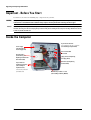
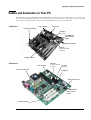
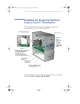
hp vectra xe310 upgrade guide hp business pcs www.hp.com/go/vectrasupport Notice The information contained in this document is subject to change without notice. Hewlett-Packard makes no warranty of any kind with regard to this material, including, but not limited to, the implied warranties of merchantability and fitness for a particular purpose. Hewlett-Packard shall not be liable for errors contained herein or for incidental or consequential damages in connection with the furnishing, performance, or use of this material. This document contains proprietary information that is protected by copyright. All rights are reserved. No part of this document may be photocopied, reproduced, or translated to another language without the prior written consent of Hewlett-Packard Company. Adobe, Acrobat and Acrobat Reader™ are trademarks or registered trademarks of Adobe Systems Incorporated. Microsoft, MS-DOS, Windows and Windows NT are U.S registered trademarks of Microsoft Corporation. HP France Business Desktop Division 38053 Grenoble Cedex 9 France © 2001 Hewlett-Packard Company Important Ergonomic Information Improper and prolonged use of keyboards and input devices are among those tasks associated with repetitive strain injury (RSI) to soft tissues in the hands and arms. If you do experience discomfort or pains while using any computing equipment, discontinue use immediately and consult your physician as soon as possible. Your comfort and safety are our primary concern. Consequently, we strongly recommend that you read HP’s ergonomic information before using your PC. For detailed information, refer to HP’s online version of “Working in Comfort” which is preloaded on your HP PC’s hard disk or visit HP’s Working in Comfort Web site at: www.hp.com/ergo/. How to Recognize Your HP Vectra XE310 Model and Series There are two versions of the HP Vectra XE310 PC: the Series 1 and the Series 2. If you are uncertain of which HP XE310 model and series you have, this information can be found on the label on the side of the PC: • ‘XE310’ indicates a Series 1 model • ‘XE310 Series 2’ indicates a Series 2 model This manual provides information that applies to both models unless otherwise stated. 3 Information Roadmap Use the icon in Acrobat Reader to search for information in this PDF. The following types of information are available for HP Business PCs: Troubleshooting See the HP Troubleshooting Guide (this document). The Troubleshooting Guide will help you solve problems with your HP Business PC. It is available in PDF format on the HP support web site (www.hp.com/go/vectrasupport). The Troubleshooting Guide will help you: • Find out what to do first if you encounter a problem with your computer • Identify the problem area and provide a possible solution • Find further HP service and support if you still can’t solve the problem • Collect relevant information on your computer before contacting support. Technical Reference See the HP Technical Reference Manual. The Technical Reference Manual, available in PDF format on the HP support web site (www.hp.com/go/vectrasupport), provides information on: • Your computer’s hardware components • The drivers, software and BIOS used in your computer. Installing, Configuring, Upgrading See the HP Service Handbook Chapter or the HP Upgrade Guide. The Service Handbook Chapter, available in PDF format on the HP support web site (www.hp.com/go/vectrasupport), provides information on: • HP Business PC configurations • Replacement parts • Available accessories. The Upgrade Guide will help you upgrade and replace components in your HP Business PC, including the hard drive, memory, battery, power supply, and optical drives. More information is available on the HP support web site (www.hp.com/go/vectrasupport). 4 Discover and use your product See the HP Quick Start card and HP Quick User’s Guide. The Quick Start card provided with your HP Business PC will help you: • Set up and begin using your HP Business PC for the first time • Upgrade and replace components in your HP Business PC, including the hard drive, processor memory, add-on cards and optical drives. More information is available on the HP support web site (www.hp.com/go/vectrasupport). • Find out where to get more information. The Quick User’s Guide provided with your HP Business PC includes basic troubleshooting information, technical specifications, warranty and legal information. Your computer’s online information Your computer may contain online help information on the hard disk, such as: • Troubleshooting and how to use HP Instant Support • Linking to useful HP web sites. If your computer is running Windows XP then you can access the Help and Support Center (HSC) via the Start menu. HSC is an application which centralizes help topics, tutorials, troubleshooting etc. Information on the hp support web site Refer to the HP support web site (www.hp.com/go/vectrasupport) for a wide range of information, including: • Downloadable documentation • Service and support options • The latest BIOS, drivers and utilities • Answers to Frequently Asked Questions. System recovery cd-roms Used for a full system recovery or alternative OS installation. Includes instructions on how to recover your preloaded software including operating system, drivers and utilities. 5 Finding Information Use the following table to determine where to locate particular types of information: Type of Information • Support phone numbers • Technical support contact information • Warranty information • How to set up your computer Location Quick User’s Guide Quick Start Card (details) Quick User’s Guide (general information) 6 • Operation of your computer Operating system and application manuals • Diagrams and detailed instructions on installing add-on devices Upgrade Guide • Internal wire connections for adding hard drives, CD-ROM, etc. • Memory expansion and replacing devices • LAN controller Technical Reference Manual • Identifying the problem Troubleshooting Guide • Information on errors • Problem solving • Troubleshooting • Parts list • Accessories list • BIOS • Connectors • IRQ • POST setup • Specifications • System board layout • Technical diagrams Service Handbook Chapter Technical Reference Manual Table of Contents Upgrading and Replacing PC Hardware Important - Before You Start. . . . . . . . . . . . . . . . . . . . . . 10 Inside the Computer . . . . . . . . . . . . . . . . . . . . . . . . . . . . 10 Cables and Connectors in Your PC. . . . . . . . . . . . . . . . . . 11 Removing and Replacing the Side Panel & Air Flow Guide 12 Installing a Memory Module . . . . . . . . . . . . . . . . . . . . . . 13 Installing an Expansion Card . . . . . . . . . . . . . . . . . . . . . . 14 Replacing the System Board . . . . . . . . . . . . . . . . . . . . . . 15 Replacing a Processor . . . . . . . . . . . . . . . . . . . . . . . . . . . 16 Replacing the Floppy Drive . . . . . . . . . . . . . . . . . . . . . . . 17 Replacing the Hard Drive. . . . . . . . . . . . . . . . . . . . . . . . . 19 Adding a Second Hard Drive . . . . . . . . . . . . . . . . . . . . . . 21 Installing an Optical Drive . . . . . . . . . . . . . . . . . . . . . . . . 22 Replacing the Power Supply Unit. . . . . . . . . . . . . . . . . . . 26 Replacing the Battery . . . . . . . . . . . . . . . . . . . . . . . . . . . 27 7 Important Safety Information For your safety, never remove the PC’s cover without first removing the power cord and any connection to a telecommunications network. Always replace the cover before switching the PC on again. For your safety, always connect equipment to a grounded electrical wall outlet. Always use a power cord with a properly grounded plug, such as the one provided with the equipment, or one in compliance with your national safety standards. The equipment can be disconnected from the power by removing the power cord from the power outlet. This means the equipment must be located close to an easily accessible electrical outlet. To avoid electrical shock, do not open the power supply. There are no user-serviceable parts inside. There is a danger of explosion if the battery is incorrectly installed. For your safety, never attempt to recharge, disassemble or burn an old battery. Only replace the battery with the same or equivalent type, as recommended by the manufacturer. The battery in this PC is a lithium battery that does not contain any heavy metals. Nevertheless, in order to protect the environment, do not dispose of batteries in household waste. Please return used batteries either to the shop from which you bought them, or to the dealer from whom you purchased your PC, or to HP, so that they can either be recycled or disposed of in the correct way. Returned used batteries will be accepted free of charge. Do not attempt to connect this product to the phone line during a lightning storm. Never install telephone jacks in wet locations unless the telephone line has been disconnected at the network interface. Never touch uninsulated telephone wires or terminals unless the telephone line has been disconnected at the network interface. Use caution when installing or modifying telephone lines. Avoid using a telephone (other than a cordless type) during a lightning storm. There may be a risk from lightning. Do not use the telephone to report a gas leak in the vicinity of the leak. Never touch or remove the communications board without first removing the connection to the telephone network. Use minimum Nº 26 AWG wire for telephone cable. Choosing a Comfortable Workspace Choose a workspace for your computer near a grounded electrical wall socket. If your monitor has a tiltswivel base, attach it to the monitor as described in the monitor manual. Position the monitor on your desk. Position the computer to allow proper ventilation and access to the cables. WARNING If you are in doubt that you can lift the equipment safely, do not try to move it without help. 8 Upgrading and Replacing PC Hardware This section describes how to: • • upgrade hardware components replace faulty components. If you want to find out about available accessories for your PC, refer to the HP accessories web site at: www.hp.com/go/pcaccessories. Upgrading and Replacing PC Hardware Important - Before You Start Read this section before installing any components in your PC. WARNING For your safety, never remove the PC’s side panel without first removing the power cord from the power outlet, and any connection to a telecommunications network. Always replace the side panel before switching the PC on again. Caution Static electricity can damage electronic components. Turn all equipment OFF. Don’t let your clothes touch the accessory. To equalize the static electricity, rest the accessory bag on top of the PC while you are removing the accessory from the bag. Handle the accessory as little as possible and with care. Inside the Computer Up to 2 Device Shelves: For CD-ROM drive, DVD, Zip or Tape drive Power supply (see Replacing the Power Supply Unit) Air Flow Guide (see Removing and Replacing the Side Panel & Air Flow Guide) Up to Three PCI Expansion Card Slots (see Installing an Expansion Card) Some slots may come with pre-installed cards 10 (see Installing an Optical Drive) One Free Hard Disk Drive Shelf Floppy drive (see Replacing the Floppy Drive) Hard drive (see Replacing the Hard Drive) Main memory modules - 2 slots (see Installing a Memory Module) Upgrading and Replacing PC Hardware Cables and Connectors in Your PC Internal drives such as hard drives and CD-ROM drives use data and power cables. These are connected to the system board and internal devices as shown below. You must also connect the power connector, status panel connector and CD audio connector (if a CD-ROM is fitted) to the system board. XE310 Series 1 Power connector Floppy drive Processor fan connector IDE device (Hard drive) Clear CMOS and Clear Passwords jumpers Status panel connector IDE device (CD-ROM, DVD-ROM or Zip drive) CD audio connector XE310 Series 2 Power connector Processor fan connector IDE device (CD-ROM, DVD-ROM IDE device or Zip drive) (Hard drive) Floppy drive Status panel connector Clear CMOS and Clear Passwords jumpers CD audio connector 11 Upgrading and Replacing PC Hardware Removing and Replacing the Side Panel & Air Flow Guide WARNING For your safety, disconnect the power cord and all external cables. 1 Place the PC on a flat surface and stand behind it. 2 Disconnect all cables from the rear of the PC. 3 Undo the two thumb screws on the back of the PC then slide back and lift off the side panel. Thumb screw Thumb screw 4 Push down on the two clips, ease the airflow guide backwards and lift off. 5 Reverse the process described in Steps 2 to 4 to replace the side panel and air flow guide. 12 Upgrading and Replacing PC Hardware Installing a Memory Module WARNING For your safety, disconnect the power cord and all external cables. 1 Switch off the PC, disconnect the power cord and remove the PC’s side panel and air flow guide (refer to “Removing and Replacing the Side Panel & Air Flow Guide” on page 12). 2 Lay the PC on its side so you can access the system board. XE310 Series 1 XE310 Series 2 Position of memory modules 3 Either remove the module you want to replace or locate an empty memory module socket. 4 Make sure that the socket’s clips are open. 5 Align the grooves on the bottom of the module with the corresponding marks on the socket and push it firmly into place. The clips close automatically. 6 Replace the PC’s air flow guide and side panel (refer to “Removing and Replacing the Side Panel & Air Flow Guide” on page 12). 7 Reconnect the power cord. 13 Upgrading and Replacing PC Hardware Installing an Expansion Card Note For your safety, disconnect the power cord and all external cables. 1 Switch off the PC, disconnect the power cord and remove the PC’s side panel (refer to “Removing and Replacing the Side Panel & Air Flow Guide” on page 12). 2 Locate the slot you want to use. • If fitting a card in an empty slot, undo the screw holding the slot cover in place and remove it. • If replacing a card in an expansion slot, undo the screw holding the card in place and lift it out. 3 Aligning the new card carefully, press it firmly into the socket and tighten the retaining screw. 4 Replace the PC’s side panel (refer to “Removing and Replacing the Side Panel & Air Flow Guide” on page 12). 5 Reconnect the power cord. 14 Upgrading and Replacing PC Hardware Replacing the System Board WARNING For your safety, disconnect the power cord and all external cables. 1 Switch off the PC, disconnect all cables and remove the PC’s side panel and air flow guide (refer to “Removing and Replacing the Side Panel & Air Flow Guide” on page 12). 2 Lay the PC on its side. 3 Remove all cables from the system board. 4 Remove any components you want to reuse such as the processor or memory modules. Refer to the appropriate section for instructions on removing the individual components. 5 Remove the hard disk drive/floppy disk drive tray (refer “Replacing the Hard Drive” on page 19). 6 Remove the seven screws shown below. Series 1 Series 2 7 Lift the system board clear of the PC’s chassis. Be careful when removing the rear connectors from the PC’s rear panel. 8 Replace the system board in the PC, ensuring that it is properly in place and attach the screws. 9 Install any components removed from the old system board in the new board. Refer to the appropriate sections in this manual for instructions on installing the individual components. 10 Replace the hard disk drive/floppy disk drive tray (“Replacing the Hard Drive” on page 19) 11 Reconnect all connectors and cables to the system board. 12 Replace the PC’s side panel and air flow guide (refer to “Removing and Replacing the Side Panel & Air Flow Guide” on page 12) and reconnect all external cables. 15 Upgrading and Replacing PC Hardware Replacing a Processor WARNING For your safety, disconnect the power cord and all external cables. 1 Switch off the PC, disconnect the power cord and remove the PC’s side panel and air flow guide (refer to “Removing and Replacing the Side Panel & Air Flow Guide” on page 12). 2 Lay the PC on its side for easy access to the processor. 3 Disconnect the processor fan cable from the system board. 4 Unclip and remove the heatsink/fan unit by pushing down on the clip. 5 Raise the lever to the side of the socket to release the old processor, then lift it out. 6 Install the new processor in the socket, with its corner markers facing the corner markers on the socket, then lower the lever to lock it in place. 7 Fit the new heatsink/fan unit and fasten its retention clip first on one side then on the other. NOTE If reinstalling the old heatsink, ensure that you completely remove the old thermal interface material from the bottom of the heatsink. This can be done using your thumbnail. Once the heatsink is clean, install the new thermal interface provided with the new processor. 8 Reconnect the processor fan cable. 9 Replace the PC’s side panel and air flow guide (refer to “Removing and Replacing the Side Panel & Air Flow Guide” on page 12) and reconnect the power cord. 16 Upgrading and Replacing PC Hardware Replacing the Floppy Drive WARNING For your safety, disconnect the power cord and all external cables. 1 Switch off the PC, disconnect the power cord and remove the PC’s side panel and air flow guide (refer to “Removing and Replacing the Side Panel & Air Flow Guide” on page 12). 2 Press the tab on the hard disk drive/floppy disk drive tray and pull the tray out part of the way. Press here 3 Disconnect all cables at the back of the floppy disk drive and hard disk drive. 4 Remove the drive tray from the PC. 5 Remove the two floppy drive fixing screws (one on either side of the drive tray), noting carefully the position of these screws. 6 Slide the floppy drive out through the front of the tray. 17 Upgrading and Replacing PC Hardware 7 Slide the new floppy drive into the floppy drive bay. 8 Replace the two screws. 9 Reconnect the cables at the back of the floppy disk drive and hard disk drive and replace the drive tray in the PC, ensuring that it is firmly positioned. 10 Replace the PC’s side panel and air flow guide (refer to “Removing and Replacing the Side Panel & Air Flow Guide” on page 12). 11 Reconnect the power cord. 18 Upgrading and Replacing PC Hardware Replacing the Hard Drive For information on recovering the contents of your old hard drive, refer to the Vectra XE310 Troubleshooting Guide, available in PDF format from the HP Vectra support website (www.hp.com/go/vectrasupport). WARNING For your safety, disconnect the power cord and all external cables. 1 Switch off the PC, disconnect the power cord and remove the PC’s side panel and air flow guide (refer to “Removing and Replacing the Side Panel & Air Flow Guide” on page 12). 2 Press the tab on the hard disk drive/floppy disk drive tray and pull the tray out part of the way. Press here 3 Disconnect the cables at the back of the floppy disk drive and hard disk drive. 4 Remove the drive tray from the PC. 5 Remove the three hard disk drive fixing screws (two on one side of the tray as shown below, and one on the other side), noting carefully the position of these screws. Caution Take care when handling the hard drive. A one-quarter inch drop can damage it. 6 Slide the drive in the direction shown until it is released from the tray, holding the drive tray firmly so as not to drop it. 19 Upgrading and Replacing PC Hardware 7 Slide the new drive into the hard drive tray. 8 Replace the three screws. 9 Reconnect the cables at the back of the floppy disk drive and hard disk drive and replace the drive tray in the PC, ensuring that it is firmly positioned. 10 Replace the PC’s side panel and air flow guide (refer to “Removing and Replacing the Side Panel & Air Flow Guide” on page 12). 11 Reconnect the power cord. 20 Upgrading and Replacing PC Hardware Adding a Second Hard Drive WARNING For your safety, disconnect the power cord and all external cables. You can add a second hard drive in the drive tray provided. To do this: 1 Switch off the PC, disconnect the power cord and remove the PC’s side panel and air flow guide (refer to “Removing and Replacing the Side Panel & Air Flow Guide” on page 12). 2 Press the tab on the hard disk drive/floppy disk drive tray and pull the tray out part of the way. Press here and pull tray outwards 3 Disconnect all cables at the back of the floppy disk drive and hard disk drive. 4 Remove the drive tray from the PC. Note Due to cable restrictions only the hard drive installed in the upper tray can be used as the master. If you want to retain the original drive as master you must remove it from the lower tray, install it in the upper tray and then install the second hard drive in the lower tray. 5 Slide in the new hard drive in the position shown and fasten the three screws to secure it in position in the drive tray. Fasten screws here and one on the other side of drive tray 6 Attach all data and power connectors. Assuming you want to use the original hard drive to boot your PC from, attach the end connector (marked MASTER) to this drive and the middle connector (marked SLAVE) to the new drive. 7 Replace the drive tray in the PC. 8 Verify the new configuration by checking the main menu of the BIOS setup. To access the menu, press F8 when the HP logo appears during startup, then select Enter Setup. Note If you want to boot on the new hard drive, ensure that you have installed all the required operating system and HP drivers on the newly installed drive. To reinstall operating system and HP drivers, use the Recovery CD-ROMs provided with the PC. In addition, you can find the most up-to-date versions of HP drivers on HP’s Web site at: www.hp.com/go/vectrasupport. 9 Replace the PC’s side panel and air flow guide (refer to “Removing and Replacing the Side Panel & Air Flow Guide” on page 12). 10 Reconnect the power cord. 21 Upgrading and Replacing PC Hardware Installing an Optical Drive An optical drive can be a CD-ROM, DVD-ROM, CD-RW or DVD-RW drive. Replacing a Drive in the Top Bay WARNING To avoid electrical shock and harm to your eyes by laser, do not open the laser module. The laser module should be serviced by service personnel only. Do not attempt to make any adjustment to the laser unit. Refer to the label on the CD-ROM for power requirements and wavelength. This product is a class 1 laser product. For your safety, disconnect the power cord and all external cables. 1 Switch off the PC, disconnect the power cord and remove the PC’s side panel and air flow guide (refer to “Removing and Replacing the Side Panel & Air Flow Guide” on page 12). 2 Disconnect the cables from the rear of the drive. 3 Remove the two retaining screws, noting carefully the position of these screws. 22 Upgrading and Replacing PC Hardware 4 Slide the old drive out of the front of the PC. 5 Check that the jumpers on the rear of the new drive are set to CS (cable select) mode. 6 Slide the new drive in from the front of the PC. 7 Replace the two screws. 8 Replace the audio, data and power cables. 9 Replace the PC’s side panel and air flow guide (refer to “Removing and Replacing the Side Panel & Air Flow Guide” on page 12). 10 Reconnect the power cord. 23 Upgrading and Replacing PC Hardware Installing a Drive in the Lower Expansion Bay WARNING For your safety, disconnect the power cord and all external cables. 1 Switch off the PC, disconnect the power cord and remove the PC’s side panel and air flow guide (refer to “Removing and Replacing the Side Panel & Air Flow Guide” on page 12). 2 Remove the plastic masking plate from the front panel by prising the retaining tab open with a screwdriver. masking plate retaining tab 3 Check that the jumpers on the rear of the new drive are set to CS (cable select) mode. 4 Slide the drive in from the front of the PC, aligning it with the drive in place in the shelf above. 5 Tighten the two screws that fasten the drive to the bay. 6 Connect the data and power cables, and for a DVD or CD-ROM drive, the audio cable. 24 • If this is the second device installed in the expansion bays, fit the data connector marked SLAVE. • If this is the only device, fit the end CD connector marked MASTER. Upgrading and Replacing PC Hardware 7 Replace the PC’s side panel and air flow guide (refer to “Removing and Replacing the Side Panel & Air Flow Guide” on page 12). 8 Reconnect the power cord. 25 Upgrading and Replacing PC Hardware Replacing the Power Supply Unit WARNING Hewlett-Packard does not support power supply upgrades. This information is provided to help you replace a defective power supply unit. For your safety, only replace with a power supply provided by HP support services. To avoid electrical shock, do not open the power supply. There are no user-serviceable parts inside. For your safety, disconnect the power cord and all external cables. 1 Switch off the PC, disconnect the power cord and remove the PC’s side panel and air flow guide (refer to “Removing and Replacing the Side Panel & Air Flow Guide” on page 12). 2 Remove the three screws from the rear of the PC. Screws Voltage switch 3 Disconnect all power cables from installed drives and from the system board. 4 Lift the power supply unit out of the PC. 5 Place the new power supply unit inside the PC and tighten the three screws on the rear of the PC. 6 Reconnect all the power cables to the drives and the system board. 7 Replace the PC’s side panel and air flow guide (refer to “Removing and Replacing the Side Panel & Air Flow Guide” on page 12). 8 Check that the voltage switch is set correctly for your country (the voltage is set during manufacturing and should already be correct). 9 Reconnect the power cord. 26 Upgrading and Replacing PC Hardware Replacing the Battery WARNING There is a danger of explosion if the battery is incorrectly installed. For your safety, never attempt to recharge, disassemble or burn the old battery. Replace the battery only with the same or equivalent type recommended by the manufacturer. The battery in this PC is a lithium battery which does not contain heavy metals, nevertheless, in order to protect the environment, do not dispose of batteries in household waste. Please return used batteries to the shop from which you bought them, or to the dealer from which you purchased your PC, or to HP, so that they can either be recycled or disposed of in an environmentally sound way. Returned used batteries will be accepted free of charge. For your safety, disconnect the power cord and all external cables. 1 Switch off the PC, disconnect the power cord and remove the PC’s side panel (refer to “Removing and Replacing the Side Panel & Air Flow Guide” on page 12). 2 Lay the PC on its side to allow easy access to the system board. XE310 Series 1 Position of battery XE310 Series 2 Position of battery 3 Remove the old battery by pressing the retaining clip with a flat-headed screwdriver and lifting the battery clear of the battery holder. 4 Place the new battery in the battery holder, with the “+” sign on top and ensure that it is properly seated. 5 Replace the PC’s side panel (refer to “Removing and Replacing the Side Panel & Air Flow Guide” on page 12). 6 Reconnect the power cord. 27