1
OPERATING INSTRUCTIONS
Read this manual carefully before you use this product and keep it handy for future
reference.
For safety, please follow the instructions in this manual.
RICOH COMPANY, LTD.
15-5, 1 chome, Minami-Aoyama, Minato-ku, Tokyo
Telephone: Tokyo 3479-3111
U.S.A.
RICOH CORPORATION
5 Dedrick Place
West Caldwell, New Jersey 07006
Phone: +1-973-882-2000
Spain
RICOH ESPAÑA S.A.
Avda. Litoral Mar, 12-14,
08005 Barcelona
Phone: +34-(0)93-295-7600
The Netherlands
RICOH EUROPE B.V.
Groenelaan 3, 1186 AA, Amstelveen
Phone: +31-(0)20-5474111
Italy
RICOH ITALIA SpA
Via della Metallurgia 12,
37139 Verona
Phone: +39-(0)45-8181500
United Kingdom
RICOH UK LTD.
Ricoh House,
1 Plane Tree Crescent, Feltham,
Middlesex, TW13 7HG
Phone: +44-(0)181-261-4000
Germany
RICOH DEUTSCHLAND GmbH
Mergenthalerallee 38-40,
65760 Eschborn
Phone: +49-(0)6196-9060
France
RICOH FRANCE S.A.
383, Avenue du Général de Gaulle
BP 307-92143 Clamart Cedex
Phone: +33-(0)1-40-94-38-38
Model number: G024–57
Printed in Japan
UE USA G024-8607
Hong Kong
RICOH HONG KONG LTD.
23/F., China Overseas Building,
139, Hennessy Road,
Wan Chai, Hong Kong
Phone: +852-2862-2888
Singapore
RICOH ASIA PACIFIC PTE.LTD.
260 Orchard Road,
#15-01/02 The Heeren,
Singapore 238855
Phone: +65-830-5888
RICOH COLOR LASER AP305 OPERATING INSTRUCTIONS
Overseas Affiliates
Introduction
This manual contains detailed instructions on the operation and maintenance of this machine. To get
maximum versatility from this machine all operators should carefully read and follow the instructions in
this manual. Please keep this manual in a handy place near the machine.
Please read the Safety Information before using this machine. It contains important information related
to USER SAFETY and PREVENTING EQUIPMENT PROBLEMS.
Power Source
120 V, 60 Hz, 10 A or more
Please be sure to connect the power cord to a power source as above.
Operator Safety:
This machine is considered a CDRH class I laser device, safe for office/ EDP use. The machine contains 10-milliwatt, 760 - 800 nanometer wavelength, GaAIAs laser diode. Direct (or indirect reflected)
eye contact with the laser beam might cause serious eye damage. Safety precautions and interlock
mechanisms have been designed to prevent any possible laser beam exposure to the operator.
Laser Safety:
The Center for Devices and Radiological Health (CDRH) prohibits the repair of laser-based optical unit
in the field. The optical housing unit can only be repaired in a factory or at a location with the requisite
equipment. The laser subsystem is replaceable in the field by a qualified Customer Engineer. The laser
chassis is not repairable in the field. Customer engineers are therefore directed to return all chassis
and laser subsystems to the factory or service depot when replacement or the optical subsystem is required.
Important
Parts of this manual are subject to change without prior notice. In no event will the company be liable
for direct, indirect, special, incidental, or consequential damages as a result of handling or operating
the machine.
Caution:
Use of controls or adjustment or performance of procedures other than those specified in this manual
might result in hazardous radiation exposure.
Do not attempt any maintenance or troubleshooting other than that mentioned in this manual. This machine contains a laser beam generator and direct exposure to laser beams can cause permanent eye
damage.
Two kinds of size notation are employed in this manual. With this machine refer to the Inch version.
Ricoh shall not be responsible for any damage or expense that might result from the use of parts other
than genuine Ricoh parts in your Ricoh office product.
For good copy quality, Ricoh recommends that you use genuine Ricoh toner.
Note to users in the United States of America
Notice:
This equipment has been tested and found to comply with the limits for a Class B digital device, pursuant to Part 15
of the FCC Rules. These limits are designed to provide reasonable protection against harmful interference in a residential installation. This equipment generates, uses and can radiate radio frequency energy and, if not installed and
used in accordance with the instructions, may cause harmful interference to radio communications.
However, there is no guarantee that interference will not occur in a particular installation. If this equipment does
cause harmful interference to radio or television reception, which can be determined by turning the equipment off
and on, the user is encouraged to try to correct the interference by one more of the following measures:
Reorient or relocate the receiving antenna.
Increase the separation between the equipment and receiver.
Connect the equipment into an outlet on a circuit different from that to which the receiver is connected.
Consult the dealer or an experienced radio/TV technician for help.
Warning
Changes or modifications not expressly approved by the party responsible for compliance could void the user's authority to operate the equipment.
Caution (in case of 100BaseTX environment):
Properly shielded and grounded cables (STP) and connectors must be used for connections to host computer (and/
or peripheral) in order to meet FCC emission limits.
Declaration of Conformity
Product Name: Printer
Model Number: G024–57
Responsible party: Ricoh Corporation
Address: 5 Dedrick Place, West Caldwell, NJ 07006
Telephone number: 973-882-2000
This device complies with part 15 of FCC Rules.
Operation is subject to the following two conditions:
1. This device may not cause harmful interference, and
2. this device must accept any interference received,
including interference that may cause undesired operation.
Properly shielded cables must be used for connections to host computer (and/or peripheral) in order to
meet FCC emission limits.
Network interface cable with ferrite core must be used for RF interference suppression.
Note to users in Canada
Note:
This Class B digital apparatus complies with Canadian ICES-003.
Remarque concernant les utilisateurs au Canada
Avertissement:
Cet appareil numérique de la classe B est conforme à la norme NMB-003 du Canada.
In accordance with IEC 60417, this machine uses the following symbols for the main power switch:
a means POWER ON.
b means POWER OFF.
Copyright © 1999 Ricoh Co., Ltd.
Introduction
This manual contains detailed instructions on the operation and maintenance of this machine. To get
maximum versatility from this machine all operators should carefully read and follow the instructions in
this manual. Please keep this manual in a handy place near the machine.
Please read the Safety Information before using this machine. It contains important information related
to USER SAFETY and PREVENTING EQUIPMENT PROBLEMS.
Power Source
120 V, 60 Hz, 10 A or more
Please be sure to connect the power cord to a power source as above.
Operator Safety:
This machine is considered a CDRH class I laser device, safe for office/ EDP use. The machine contains 10-milliwatt, 760 - 800 nanometer wavelength, GaAIAs laser diode. Direct (or indirect reflected)
eye contact with the laser beam might cause serious eye damage. Safety precautions and interlock
mechanisms have been designed to prevent any possible laser beam exposure to the operator.
Laser Safety:
The Center for Devices and Radiological Health (CDRH) prohibits the repair of laser-based optical unit
in the field. The optical housing unit can only be repaired in a factory or at a location with the requisite
equipment. The laser subsystem is replaceable in the field by a qualified Customer Engineer. The laser
chassis is not repairable in the field. Customer engineers are therefore directed to return all chassis
and laser subsystems to the factory or service depot when replacement or the optical subsystem is required.
Important
Parts of this manual are subject to change without prior notice. In no event will the company be liable
for direct, indirect, special, incidental, or consequential damages as a result of handling or operating
the machine.
Caution:
Use of controls or adjustment or performance of procedures other than those specified in this manual
might result in hazardous radiation exposure.
Do not attempt any maintenance or troubleshooting other than that mentioned in this manual. This machine contains a laser beam generator and direct exposure to laser beams can cause permanent eye
damage.
Two kinds of size notation are employed in this manual. With this machine refer to the Inch version.
Savin shall not be responsible for any damage or expense that might result from the use of parts other
than genuine Savin parts in your Savin office product.
For good copy quality, Savin recommends that you use genuine Savin toner.
Note to users in the United States of America
Notice:
This equipment has been tested and found to comply with the limits for a Class B digital device, pursuant to Part 15
of the FCC Rules. These limits are designed to provide reasonable protection against harmful interference in a residential installation. This equipment generates, uses and can radiate radio frequency energy and, if not installed and
used in accordance with the instructions, may cause harmful interference to radio communications.
However, there is no guarantee that interference will not occur in a particular installation. If this equipment does
cause harmful interference to radio or television reception, which can be determined by turning the equipment off
and on, the user is encouraged to try to correct the interference by one more of the following measures:
Reorient or relocate the receiving antenna.
Increase the separation between the equipment and receiver.
Connect the equipment into an outlet on a circuit different from that to which the receiver is connected.
Consult the dealer or an experienced radio/TV technician for help.
Warning
Changes or modifications not expressly approved by the party responsible for compliance could void the user's authority to operate the equipment.
Caution (in case of 100BaseTX environment):
Properly shielded and grounded cables (STP) and connectors must be used for connections to host computer (and/
or peripheral) in order to meet FCC emission limits.
Declaration of Conformity
Product Name: Printer
Model Number: G024–57
Responsible party: Ricoh Corporation
Address: 5 Dedrick Place, West Caldwell, NJ 07006
Telephone number: 973-882-2000
This device complies with part 15 of FCC Rules.
Operation is subject to the following two conditions:
1. This device may not cause harmful interference, and
2. this device must accept any interference received,
including interference that may cause undesired operation.
Properly shielded cables must be used for connections to host computer (and/or peripheral) in order to
meet FCC emission limits.
Network interface cable with ferrite core must be used for RF interference suppression.
Note to users in Canada
Note:
This Class B digital apparatus complies with Canadian ICES-003.
Remarque concernant les utilisateurs au Canada
Avertissement:
Cet appareil numérique de la classe B est conforme à la norme NMB-003 du Canada.
In accordance with IEC 60417, this machine uses the following symbols for the main power switch:
a means POWER ON.
b means POWER OFF.
Introduction
This manual contains detailed instructions on the operation and maintenance of this machine. To get
maximum versatility from this machine all operators should carefully read and follow the instructions in
this manual. Please keep this manual in a handy place near the machine.
Please read the Safety Information before using this machine. It contains important information related
to USER SAFETY and PREVENTING EQUIPMENT PROBLEMS.
Power Source
120 V, 60 Hz, 10 A or more
Please be sure to connect the power cord to a power source as above.
Operator Safety:
This machine is considered a CDRH class I laser device, safe for office/ EDP use. The machine contains 10-milliwatt, 760 - 800 nanometer wavelength, GaAIAs laser diode. Direct (or indirect reflected)
eye contact with the laser beam might cause serious eye damage. Safety precautions and interlock
mechanisms have been designed to prevent any possible laser beam exposure to the operator.
Laser Safety:
The Center for Devices and Radiological Health (CDRH) prohibits the repair of laser-based optical unit
in the field. The optical housing unit can only be repaired in a factory or at a location with the requisite
equipment. The laser subsystem is replaceable in the field by a qualified Customer Engineer. The laser
chassis is not repairable in the field. Customer engineers are therefore directed to return all chassis
and laser subsystems to the factory or service depot when replacement or the optical subsystem is required.
Important
Parts of this manual are subject to change without prior notice. In no event will the company be liable
for direct, indirect, special, incidental, or consequential damages as a result of handling or operating
the machine.
Caution:
Use of controls or adjustment or performance of procedures other than those specified in this manual
might result in hazardous radiation exposure.
Do not attempt any maintenance or troubleshooting other than that mentioned in this manual. This machine contains a laser beam generator and direct exposure to laser beams can cause permanent eye
damage.
Two kinds of size notation are employed in this manual. With this machine refer to the Inch version.
Gestetner shall not be responsible for any damage or expense that might result from the use of parts
other than genuine Gestetner parts in your Gestetner office product.
For good copy quality, Gestetner recommends that you use genuine Gestetner toner.
Note to users in the United States of America
Notice:
This equipment has been tested and found to comply with the limits for a Class B digital device, pursuant to Part 15
of the FCC Rules. These limits are designed to provide reasonable protection against harmful interference in a residential installation. This equipment generates, uses and can radiate radio frequency energy and, if not installed and
used in accordance with the instructions, may cause harmful interference to radio communications.
However, there is no guarantee that interference will not occur in a particular installation. If this equipment does
cause harmful interference to radio or television reception, which can be determined by turning the equipment off
and on, the user is encouraged to try to correct the interference by one more of the following measures:
Reorient or relocate the receiving antenna.
Increase the separation between the equipment and receiver.
Connect the equipment into an outlet on a circuit different from that to which the receiver is connected.
Consult the dealer or an experienced radio/TV technician for help.
Warning
Changes or modifications not expressly approved by the party responsible for compliance could void the user's authority to operate the equipment.
Caution (in case of 100BaseTX environment):
Properly shielded and grounded cables (STP) and connectors must be used for connections to host computer (and/
or peripheral) in order to meet FCC emission limits.
Declaration of Conformity
Product Name: Printer
Model Number: G024–57
Responsible party: Ricoh Corporation
Address: 5 Dedrick Place, West Caldwell, NJ 07006
Telephone number: 973-882-2000
This device complies with part 15 of FCC Rules.
Operation is subject to the following two conditions:
1. This device may not cause harmful interference, and
2. this device must accept any interference received,
including interference that may cause undesired operation.
Properly shielded cables must be used for connections to host computer (and/or peripheral) in order to
meet FCC emission limits.
Network interface cable with ferrite core must be used for RF interference suppression.
Note to users in Canada
Note:
This Class B digital apparatus complies with Canadian ICES-003.
Remarque concernant les utilisateurs au Canada
Avertissement:
Cet appareil numérique de la classe B est conforme à la norme NMB-003 du Canada.
In accordance with IEC 60417, this machine uses the following symbols for the main power switch:
a means POWER ON.
b means POWER OFF.
Trademarks
Microsoft®, Windows®, Windows NT®, and MS-DOS® are registered trademarks of Microsoft Corporation in the United States and/or other countries.
PostScript® is a registered trademark of Adobe Systems. Incorporated.
AppleTalk, Apple, and TrueType are registered trademarks of Apple Computer,
Incorporated.
Other product names used herein are for identification purposes only and might
be trademarks of their respective companies. We disclaim any and all rights in
those marks.
Notes:
Some illustrations might be slightly different from your machine.
Certain options might not be available in some countries. For details, please contact your local dealer.
Notes:
The proper names of the Windows operating systems are as follows:
• Microsoft® Windows® 95 operating system
• Microsoft® Windows® 98 operating system
• Microsoft® Windows® for Workgroups operating system Version 3.11
• Microsoft® Windows NT® Server network operating system Version 4.0
• Microsoft® Windows NT® Workstation operating system Version 4.0
i
Safety Information
When using your equipment, the following safety precautions should always be
followed.
Safety During Operation
In this manual, the following important symbols are used:
R WARNING:
Indicates a potentially hazardous situation which, if instructions are
not followed, could result in death or serious injury.
R CAUTION:
Indicates a potentially hazardous situation which, if instructions are not followed, may result in minor or moderate injury or damage to property.
ii
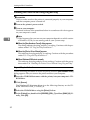
R WARNING:
• Connect the power cord directly into a wall outlet and never use an extension cord.
• Disconnect the power plug (by pulling the plug, not the cable) if the
power cable or plug becomes frayed or otherwise damaged.
• To avoid hazardous electric shock or laser radiation exposure, do not
remove any covers or screws other than those specified in this manual.
• Turn off the power and disconnect the power plug (by pulling the
plug, not the cable) if any of the following conditions exists:
• You spill something into the equipment.
• You suspect that your equipment needs service or repair.
• Your equipment's cover has been damaged.
• Do not incinerate spilled toner or used toner. Toner dust might ignite
when exposed to an open flame.
• Disposal can take place at our authorized dealer or at appropriate collection sites.
• If you dispose of the used toner containers yourself, dispose of them
according to your local regulations.
iii
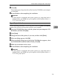
R CAUTION:
• Protect the equipment from dampness or wet weather, such as rain, snow,
and so on.
• Unplug the power cord from the wall socket before you move the equipment. While moving the equipment, you should take care that the power
cord will not be damaged under the equipment.
• When you disconnect the power plug from the wall socket, always pull the
plug (not the cable).
• Do not allow paper clips, staples, or other small metallic objects to fall inside the equipment.
• Do not eat or swallow toner.
• Keep toner (used or unused) and toner cartridge out of reach of children.
• For environmental reasons, do not dispose of the equipment or expended
supply's wastes at a household waste a collection point. Disposal can take
place at our authorized dealer or at an appropriate collection site.
• Our products are engineered to meet the highest standards of quality and
functionality. When purchasing expendable supplies, we recommend using
only those specified by an authorized dealer.
• The inside of the machine could be very hot. Do not touch the parts with a
label indicating the “hot surface”. Otherwise, it could cause a personal burn.
• If you use this printer in a cold area, leave the printer on. Otherwise, severe
cold might damage sensitive components inside the printer.
iv
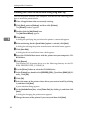
Energy Star Program
As an ENERGY STAR Partner, we have determined that this machine model meets the ENERGY STAR Guidelines for energy efficiency.
The ENERGY STAR Guidelines intend to establish an international energy-saving system for developing and introducing energy-efficient office equipment to deal with environmental issues, such as global warming.
When a product meets the ENERGY STAR Guidelines for energy efficiency, the Partner shall place the ENERGY STAR logo onto the machine model.
This product was designed to reduce the environmental impact associated with office
equipment by means of energy-saving features, such as Low-power mode.
❖ Low-power mode (Energy Saver mode)
This printer automatically lowers its power consumption 60 minutes after the
last operation has been completed when the Energy Level is set to level 1. To
exit Low-power (Energy Saver) mode, press any key on the operation panel.
To change the setting of the Energy Saver mode, see P.95 “Making Printer Settings with the Operation Panel”.
❖ Specifications
Lower-power mode
Power Consumption
45W or less
(Energy Saver mode)
Default Time
60 minutes
- Recycled Paper
Please contact your sales or service representative for recommended recycled
paper types that may be used in this machine.
v
Color Guide
Color Printing Basics
Additive (Emitted) and Subtractive (Reflected) Color Models
All light is a mixture of red, green, and blue, which is normally called the RGB
model. When red, green, and blue are of equal intensities, the RGB color model
produces white.
red
green
blue
Note
❒ RGB is also called additive or emitted color. The colors on your computer
screen are produced by varying the intensities of RGB.
Printed color is a mixture of cyan, magenta, and yellow, which is normally called
the CMY color model. When mixed in equal proportions the CMY color model
produces black.
yellow
cyan
vi
magenta
Note
❒ CMY is also called subtractive or reflective color. Your printer uses CMY toner plus K (black) toner (CMYK color model) to provide full color printing.
The colors of the RGB color model can be mixed to produce the cyan, magenta,
and yellow of the CMY color model and vice versa. Two colors of one model are
mixed to produce the color of the other model (mixing blue and green produces
cyan, for example). The remaining color is the compliment of the color produced
(red in this example). Complimentary colors are: red and cyan, green and magenta, blue and yellow.
red
yellow
green
magenta
blue
cyan
vii
Printed Color
Your printer produces full-color output using four toner colors: cyan, magenta,
yellow, and black. These four colors make up the CMYK color model.
Note
❒ Mixing CMY in equal proportions should hypothetically produce pure black,
but imperfections in the ink cause an equal measure of these colors to produce
a muddy or dark brown. Black toner is added to the color model in order to
make it possible to produce pure black.
If an image consisted of nothing by cyan, for example, cyan toner would be used
by itself and there would be no problem producing the desired color. Full-color
printing, on the other hand, requires reproduction of tens of thousands of subtle
colors. These can be produced by controlling the relative proportions of the
CMYK toner particles printed within a unit area.
Relatively dense and light shades of the same color also can be reproduced by
controlling the volume of toner in a unit area.
viii
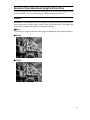
Example of Color Adjustments Using the Printer Driver
The following provides a number of examples to show you what happens when
you change the various color settings provided in the printer driver.
Resolution
Resolution is the number of dots the printer can print within one inch. Resolution is expressed in units of dpi, which stands for dots per inch. The higher the
resolution, the better the quality of the printed image.
Note
❒ Printing at a high resolution takes longer and requires more printer memory.
❖ 600 dpi
❖ 300 dpi
ix
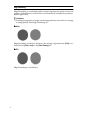
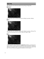
Edge Smoothing
Edge Smoothing is a technique used for improving the print quality of text and
graphics. Indentations in curved lines are automatically smoothed to produce a
clearer appearance.
Limitation
❒ Printing photographs or images containing gradations may result in a change
in image quality with Edge Smoothing on.
❖ Auto:
Edge Smoothing is effective. However, this setting is ignored when [2 bit] is selected for the [Color Level] on the [Color Setting] tab.
❖ Off:
Edge Smoothing is not effective.
x
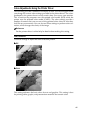
Toner Saving
Turning on Toner Saving reduces the amount of toner used for printing. This setting does not help to improve printout quality, but instead is used when printing
preliminary drafts of a document.
Limitation
❒ Turning on the Toner Saving can cause output to become blurred and result
in very thin lines not printing at all. It can cause colors to be different than expected when printing color.
❖ Off
❖ On
xi
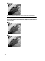
Image Printing
This setting lets you select the resolution for printing of image data.
❖ Standard
All image data with a resolution greater than 300 dpi is printed at 300 dpi.
❖ Fast
All image data with a resolution greater than 150 dpi is printed at 150 dpi. This
increases printing speed, but can make image data appear rough.
❖ Fine
Prints image data at the resolution set in [Resolution]. If 300 dpi is selected, all image data with a resolution greater than 300 dpi is printed at 300 dpi. If 600 dpi is
selected, all image data with a resolution greater than 600 dpi is printed at 600
dpi. This slows down printing speed, but produces the best quality.
xii
Color Adjustments Using the Printer Driver
The following provides a number of examples to show you what happens when
you change the various color settings provided in the printer driver. The colors
produced by the printer do not exactly match those you see on your monitor.
This is because the computer uses the emitted color model (RGB) while the
printer uses the reflected color model (CMYK). The color settings provide a
number of controls that you can use to bring printed colors closer to what they
look like on your monitor. You can also use these settings to perform color correction, which changes the clarity of the image.
Reference
See the printer driver's online help for details about making this setting.
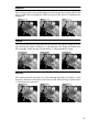
Color Correction
Use these settings to adjust the color correction pattern.
❖ Off
❖ Vivid
This setting enhances the basic colors for text and graphics. This setting is best
for printing tables, graphs, and presentation materials that contain color.
xiii
❖ Photographic
This setting enhances midtone colors similar to those seen in photographs.
Color Level
Use to set the number of colors used per dot. ( [2 bit] uses a greater number of
colors than [1 bit] )
❖ 1 bit
❖ 2 bit
xiv
Brightness
This setting controls the overall brightness of the image. Moving the slider to the
plus (+) side increases brightness, while moving it to the minus (-) side decreases
brightness.
Contrast
This setting controls the range between the darkest and lightest shade of an image. Moving the slider to the plus (+) side decreases the range and makes contrast stronger, while moving it to the minus (-) side expands the range.
Saturation
This setting controls the purity of a color. Moving the slider to the plus (+) side
increases saturation and makes colors more vivid, while moving it to the minus
(-) side decreases saturation.
xv
Color Balance
These settings let you control the relative intensity of the individual colors of the
additive color model (red, green, blue).
Note
❒ The position of the color bar also affects the complementary color relationship. Red, for example, is printed using magenta and yellow toner, so increasing the level of red also decreases the level of cyan.
xvi
Manuals for Your Printer
Manuals for Your Printer
There are two manuals that describe the procedures separately for the installation of your printer and for the operation and maintenance of your printer and
its optional equipment.
To enhance safe and efficient operation of your printer, all users should read and
follow the instructions contained in the following manuals.
❖ Quick Installation Guide
Describes the procedures for installing your printer.
❖ Operating Instructions (this manual)
Describes the procedures and necessary information on setting up and using
your printer and its optional equipment.
xvii
How to Read this Manual
Symbols
In this manual, the following symbols are used:
R WARNING:
This symbol indicates a potentially hazardous situation which, if instructions
are not followed, could result in death or serious injury.
R CAUTION:
This symbol indicates a potentially hazardous situation which, if instructions
are not followed, may result in minor or moderate injury or damage to property.
* The statements above are notes for your safety.
Important
If this instruction is not followed, paper might be misfed, originals might be
damaged, or data might be lost. Be sure to read this.
Preparation
This symbol indicates the prior knowledge or preparations required before operating.
Note
This symbol indicates precautions for operation, or actions to take after misoperation.
Limitation
This symbol indicates numerical limits, functions that cannot be used together,
or conditions in which a particular function cannot be used.
Reference
This symbol indicates a reference.
[
]
Keys that appear on the machine's panel display.
Keys and buttons that appear on the computer's display.
{
}
Keys built into the machine's operation panel.
Keys on the computer's keyboard.
xviii
TABLE OF CONTENTS
1. Getting Acquainted
Guide to the Printer ...................................................................................
Exterior-Front View .......................................................................................
Exterior-Rear View ........................................................................................
Interior ...........................................................................................................
Operation Panel ............................................................................................
Turning the Printer On and Off.................................................................
Turning On the Printer...................................................................................
Turning Off the Printer...................................................................................
1
1
3
4
5
7
7
7
2. Installing Options
Available Options ....................................................................................
Installing the Memory Unit (SIMM).........................................................
Installing the RICOH-SCRIPT2 Type305 ................................................
Installing Network Interface Board Type305.........................................
Installing the IEEE 1284 Parallel Type305 .............................................
Installing the Paper Feed Unit Type305.................................................
10
11
13
15
17
19
3. Configuring the Printer for the Network with the Operation Panel
Configuring the Printer for the Network with the Operation Panel..... 23
4. Installing the IPDL-C Printer Driver
Before Installing the Printer Driver ........................................................
Installing the Printer Drivers ........................................................................
Windows 95/98 - Installing the IPDL-C Printer Driver ..........................
Installing the Printer Driver Using Plug and Play ........................................
Installing the Printer Driver Without Using Plug and Play ...........................
Setting Up Options ......................................................................................
Canceling a Print Job ..................................................................................
Windows 3.1x - Installing the IPDL-C Printer Driver ............................
Installing the Printer Driver..........................................................................
Setting Up Options ......................................................................................
Canceling a Print Job ..................................................................................
Windows NT4.0 - Installing the IPDL-C Printer Driver..........................
Installing the Printer Driver..........................................................................
Setting Up Options ......................................................................................
Canceling a Print Job ..................................................................................
29
30
31
32
34
35
36
37
37
38
39
40
40
41
42
xix
5. Paper and Other Media
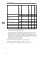
Paper and Other Media Supported by this Printer ...............................
Paper Types and Sizes ...............................................................................
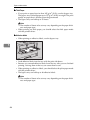
Precautions for Paper .................................................................................
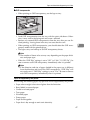
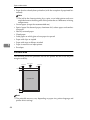
Printable Area .............................................................................................
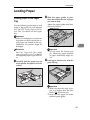
Loading Paper..........................................................................................
Loading Paper in the Paper Tray ................................................................
Loading Paper in the Bypass Tray ..............................................................
Sliding out the Output Tray Extender ..........................................................
43
43
45
48
49
49
52
54
6. Troubleshooting
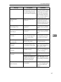
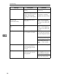
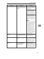
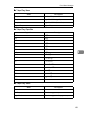
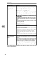
Error & Status Messages ........................................................................
Printed Error Message ................................................................................
Error & Status Messages on the Operation Panel ......................................
Getting Printer Information over the Network ..............................................
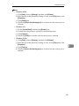
Printer Doesn't Print................................................................................
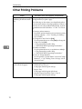
Other Printing Problems .........................................................................
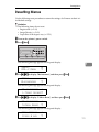
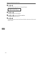
Removing Misfed Paper..........................................................................
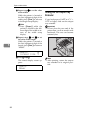
When the Message "Remove Misfeed From Tray" Appears.......................
When the Message "Open Front Cover Remove Misfeed" Appears ..........
When the Message "Remove Misfeed From Output Tray " Appears ..........
Cleaning and Adjusting the Printer .......................................................
Cleaning the Friction Pad ............................................................................
Cleaning the Charger ..................................................................................
Cleaning the Dust-proofing glass ................................................................
Adjusting the Image Density .......................................................................
Adjusting the Setting of “Registration” of the Optional Tray ........................
Replacing Consumables.........................................................................
Replacing the Toner Cartridge ....................................................................
Replacing the Photoconductor Unit.............................................................
Replacing the Fuser Oil Bottle and Ozone Filter.........................................
Replacing the Waste Toner Bottle and Charger .........................................
55
55
56
61
67
70
76
77
77
78
80
80
80
81
82
83
85
85
88
90
92
7. Making Printer Settings with the Operation Panel
Setting Menus .......................................................................................... 96
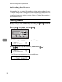
Protecting the Menus .............................................................................. 98
Protecting the Menus .................................................................................. 98
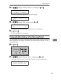
Changing the Menu Settings without Removing Protect ............................. 99
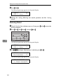
Removing Protect...................................................................................... 100
Menu Table............................................................................................. 102
Menu Settings ........................................................................................ 103
IPDL-C Menu ............................................................................................ 103
xx
System Menu ............................................................................................ 103
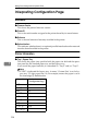
Printing the Configuration Page ..........................................................
Interpreting Configuration Page ..........................................................
Reference..................................................................................................
Printer Information.....................................................................................
Status List .................................................................................................
Error Log ...................................................................................................
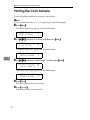
Printing the Color Sample ....................................................................
Resetting Menus....................................................................................
107
108
108
108
109
109
110
111
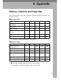
8. Appendix
Memory Capacity and Paper Size ........................................................
Low Memory..............................................................................................
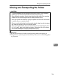
Moving and Transporting the Printer ..................................................
Specifications ........................................................................................
Mainframe .................................................................................................
Options......................................................................................................
Consumables .........................................................................................
Glossaries ..............................................................................................
113
114
115
116
116
118
120
122
INDEX...................................................................................................... 124
xxi
xxii
1. Getting Acquainted
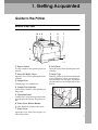
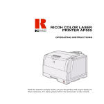
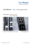
Guide to the Printer
Exterior-Front View
12 3 4
5
6
7
8
10
11
9
TFWX020E
1. Power Switch
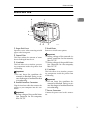
8. Left Cover
Use this switch to turn printer power on
and off.
Open this cover when replacing the toner
cartridge.
2. Fuser Oil Bottle Cover
9. Inset Grips
Open this cover when replacing the fuser
oil bottle.
Hold the printer at the location indicated
in the illustration when transporting it.
Note that there are four grips, two on the
left side and two on the right side of the
printer.
3. Output Tray
Printed pages are stacked here.
4. Output Tray Extender
Pull out this extender when printing on
long paper.
5. Operation Panel
Contains keys for printer operation and a
panel display that shows the printer status.
6. Front Cover Release Button
Use this button to open the front cover.
TFWX030E
7. Front Cover
Open this cover when accessing the inside of the printer.
1
Getting Acquainted
10. Bypass tray
Use to print onto thick paper, OHP transparencies, adhesive labels, custom size
paper as well as plain paper. When printing on custom size paper, printer driver
settings are required.
1
11. Paper Tray
Load paper into this tray for printing.
2
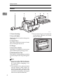
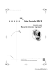
Guide to the Printer
Exterior-Rear View
2
1
1
3
4
5
6
7
TFWX040E
1. Paper Exit Cover
5. Back Plates
Open this cover when removing misfed
paper at the fusing unit.
Remove to install some options.
2. Ozone Filter
This filter reduces the amount of ozone
that is discharged into the air.
3. Ventilator
This hole allow air to circulate, preventing components inside the printer from
overheating.
Important
❒ Do not leave the ventilator obstructed or blocked. Doing so creates the danger of malfunction due
to overheating.
4. Parallel Interface Connector
Plug the interface cable that connects the
printer to your computer into this connector.
Important
❒ Rating voltage of the parallel interface connector for the computer;
Max. DC 5V.
Important
❒ Rating voltage of the network interface connector for the network;
Max. DC 5V.
❒ Rating voltage of the parallel interface connector for the computer;
Max. DC 5V.
6. Ventilator
This hole allow air to circulate, preventing components inside the printer from
overheating.
Important
❒ Do not leave the ventilator obstructed or blocked. Doing so creates the danger of malfunction due
to overheating.
7. Power Connector
Connect the power cord to this connector.
3
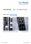
Getting Acquainted
Interior
1
1
2
3
4
5
6
TFWX051E
1. Toner Cartridge
2. Fuser Oil Bottle
❒ Do not rotate the gear on the right side
of the printer. Otherwise, the inside
belt gets damaged.
This bottle holds oil used for fusing toner
to the paper.
3. Ozone Filters
These filters reduce the amount of ozone
that is discharged into the air.
4. Charger
5. Waste Toner Bottle
This bottle is a receptacle for waste toner
generated during the printing process.
6. Photoconductor Unit
This contains a photoconductor unit that
is used to compose the image being printed.
Note
❒ Screws are used to hold the photoconductor unit in place. Be sure to remove
the screws before attempting to remove the unit.
❒ The condition of the photoconductor
unit belt directly affects output appearance and quality. Always be careful to prevent the green film in this
unit from becoming dirty or damaged.
And do not touch the black belt.
4
TFWX060E
Guide to the Printer
Operation Panel
Important
❒ Never press any operation panel keys while the Data In indicator is flashing
on the operation panel.
1
23 4 5
On Line Reset
Menu
Power
1
Error
Escape
6
Enter
Media
Data In
7 8 9
10
11
12
TFWS010E
1. Panel Display
5. {Escape}} key
The display shows the current status of
the printer and error messages.⇒ P.56
“Error & Status Messages on the Operation
Panel”
Press this key to return to the previous
condition on the panel display.
2. On Line indicator
Tells you whether the printer is on-line or
off-line.
Stays on while the printer is on-line (a
state in which the printer can receive data
from the computer).
Stays off when the printer is off-line (a
state in which printer cannot receive data).
3. {On Line}} key
Press this key to switch the printer between on-line and off-line conditions.
4. {Reset}} key
Pressing this key when the printer is offline resets the printer to its power on default settings.
Pressing this key during the on-line condition cancels the ongoing print job.
6. {U}{T} keys
Use these keys to increase or decrease
values on the panel display when making
settings.
7. {Menu}} key
Press this key to make and check the
printer settings.
8. {Media}} key
Use this key to select a tray, change the
paper size, and to make other setting for
printing.
9. {Enter}} key
Press this key to execute menu items selected on the panel display.
10. Power indicator
Stays on while the printer power is on.
Stays off when the power is turned off or
while the printer is in the Energy Saver
mode.
5
Getting Acquainted
11. Error indicator
Lights up whenever any printer error occurs. A message describing the cause of
the error also appears on the panel display.⇒ P.56 “Error & Status Messages on
the Operation Panel”
1
12. Data In indicator
Blinks while the printer is receiving data
from a computer.
Stays on if there is data to be printed.
6
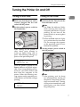
Turning the Printer On and Off
Turning the Printer On and Off
Turning On the Printer
Turning Off the Printer
A Make sure that the power cord is
A Confirm that the Data In and the
B Set the printer's power switch to
Note
❒ The Data In indicator blinks
while receiving data from the
computer and remains lit when
printing. Do not turn off the
printer while it is receiving data
or printing.
securely plugged into the wall
socket and the printer.
the On position.
1
Error indicators are off.
❒ When the Error indicator lights
up, a printer error has occurred.
Use the message that appears
on the operation panel to troubleshoot the problem.
TFWX130E
After turning on the printer, it
takes about seven minutes to
warm up before being able to
print. The following message appears on the operation panel.
B Set the printer's power switch to
the Off position.
IPDL-C
Warming Up
When the printer is turned on, the
Power indicator will blink repeatedly. Once it stops blinking and remains on, you will be able to send
data from the computer to the
printer. When the following message appears on the operation panel, the printer will be able to begin
printing.
IPDL-C
Ready
TFWX110E
The Power indicator turns off.
Note
❒ After printing, wait for about
two minutes before turning off
the printer. The printer uses this
time to maintain itself. Turning
off the printer immediately after
printing may, over time, reduce
the print quality.
7
Getting Acquainted
1
8
2. Installing Options
R CAUTION:
• Make sure to turn off the printer and wait for about 30 minutes before in-
stalling options. Not waiting for the printer to cool down can result in a burn.
• It is recommended that at least two persons are used to lift the machine.
Otherwise, the machine might fall and cause personal injury.
• When lifting the machine, use the inset grips on both sides of the machine.
Otherwise, the machine might fall and cause personal injury.
R CAUTION:
• When you move the machine, unplug the power cord from the wall socket
to avoid a fire or an electric shock.
9
Installing Options
Available Options
The following options can be installed to your printer.
Reference
For more information on the options, see P.118 “Options”. Do not use options
other than those specified in this manual.
2
1
2
3
4
TFWX180E
1. Interface Board
• Network Interface Board Type305 ⇒ P.15
• IEEE 1284 Parallel Type305 ⇒ P.17
2. Memory Unit ⇒ P.11
• Memory Unit Type204 (16MB) (SIMM)
• Memory Unit Type204 (32MB) (SIMM)
3. RICOH-SCRIPT2 Type305 ⇒ P.13
4. Paper Feed Unit Type305 ⇒ P.19
Note
❒ It is impossible to install more than two paper feed units to your printer at a time.
10
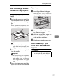
Installing the Memory Unit (SIMM)
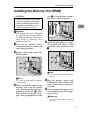
Installing the Memory Unit (SIMM)
R CAUTION:
• Make sure to turn off the printer
slot (B
B). It should make an audible click as it pops into place.
and wait for about 30 minutes
before installing options. Not
waiting for the printer to cool
down can result in a burn.
Important
❒ The memory unit can be damaged
by small amounts of static electricity. Before touching it, touch something metal to discharge static
electricity from you.
A Turn
off the printer's power
switch and remove all cables and
cords from the printer.
2
TFWX190E
D Attach the back plate to its original position, and fasten it with
screws that were removed in step
B.
B Remove
screws and remove the
left back plate.
TFWX195E
TFWX185E
Note
❒ A coin can be used to remove
the screws.
C Make sure that the notch in the
memory unit is on the bottom
side. Insert the memory unit perpendicular to the slot (A
A). Then
tilt it to the left so that it is 30 degrees from perpendicular to the
Note
❒ A coin can be used to fasten the
screws.
E Plug
the printer's power cord
back into the printer and the wall
socket. Turn on the printer's power switch.
F Print a configuration page to confirm that the memory unit is properly installed.
Reference
⇒ P.107 “Printing the Configuration Page”
11
Installing Options
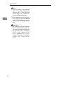
Note
❒ You can check if the memory
unit is installed properly by
checking the “Total Installed
RAM” item of the “Reference”
on the configuration page.
❒ If the memory unit is not properly installed, repeat steps A to F
again. If you fail again, contact
your sales or service representative.
2
Important
❒ To make the printer recognize
the installed option properly,
you must set up the option with
the printer driver. Windows
95/98 ⇒ P.35 “Setting Up Options”, Windows 3.1x ⇒ P.38
“Setting Up Options”, Windows
NT4.0 ⇒ P.41 “Setting Up Options”
12
Installing the RICOH-SCRIPT2 Type305
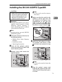
Installing the RICOH-SCRIPT2 Type305
R CAUTION:
• Make sure to turn off the printer
and wait for about 30 minutes
before installing options. Not
waiting for the printer to cool
down can result in a burn.
Important
❒ The RICOH-SCRIPT2 can be damaged by small amounts of static
electricity. Before touching it,
touch something metal to remove
static electricity from you.
Note
❒ A coin can be used to remove
the screws.
D Make sure that the notch in the
2
module is on the right side. Tilt
the module to 30 degrees from
perpendicular to the slot and
slide it into the slot (A
A). Then
push it in until it makes an audible click as it pops into place (B
B).
Note
❒ For this printer, use only RICOHSCRIPT2 Type305.
A Check the contents of the box for
the following items.
• DIMM (Dual Inline Memory
Module)
• Installation Guide
• Operating Instructions
B Turn
off the printer's power
switch and remove all cables and
cords from the printer.
TFWX200E
E Attach the back plate to its original position, and fasten it with
screws that were removed in step
C.
C Remove
screws and remove the
right back plate.
TFWX205E
Note
❒ A coin can be used to fasten the
screws.
TFWX197E
F Plug
the printer's power cord
back into the printer and the wall
socket. Turn on the printer's power switch.
13
Installing Options
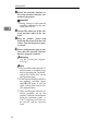
G Print a configuration page to confirm that the RICOH-SCRIPT2 is
properly installed.
Reference
⇒ P.107 “Printing the Configuration Page”
2
Note
❒ You can check if the module is
installed properly by checking
the “Firmware Version” item of
the “Reference” on the configuration page.
❒ If the RICOH-SCRIPT2 is not
properly installed, repeat steps
B to G again. If you fail again,
contact your sales or service
representative.
14
Installing Network Interface Board Type305
Installing Network Interface Board Type305
R CAUTION:
• Make sure to turn off the printer
and wait for about 30 minutes
before installing options. Not
waiting for the printer to cool
down can result in a burn.
Note
❒ Use a shielded twisted-pair (STP)
network interface cable.
Note
❒ A coin can be used to remove
the screws.
D Insert
the network interface
board into the slot and fasten it
with screws that were removed in
step C, as shown in the illustration.
2
❒ The network interface board can
be attached to either the left or the
right side of the back of your printer. This procedure is for attaching
to the left side.
❒ You cannot install two network interface boards at a time.
A Check the contents of the box for
the following items.
• Network interface board
• Ferrite core
• Installation Guide
TFWP040E
Note
❒ A coin can be used to fasten the
screws.
E Loop the network interface cable.
B Turn
off the printer's power
switch and remove all cables and
cords from the printer.
C Remove
screws and remove the
left back plate.
The loop should be about 15 cm
(6”) from the end of the cable on
the end closest to the printer.
F Attach the ferrite core to the loop.
TFWX980E
TFWX185E
15
Installing Options
G Attach the network interface ca-
ble to the network interface connector of the printer.
Important
❒ Rating voltage of the network
interface connector for the network; Max. DC 5V.
2
H Connect the other end of the network interface cable to the network.
I Plug
the printer's power cord
back into the printer and the wall
socket. Turn on the printer's power switch.
J Print a configuration page to confirm that the network interface
board is properly installed.
Reference
⇒ P.107 “Printing the Configuration Page”
Note
❒ You can check if the network interface board is installed properly by checking the “Network”
item of the “Status List” on the
configuration page.
❒ If the network interface board is
not properly installed, repeat
steps B to J again. If you fail
again, contact your sales or service representative.
❒ After installing the network interface properly, set up the
printer's network environment
using the operation panel. ⇒
P.23 “Configuring the Printer for
the Network with the Operation
Panel”
16
Installing the IEEE 1284 Parallel Type305
Installing the IEEE 1284 Parallel Type305
R CAUTION:
• Make sure to turn off the printer
and wait for about 30 minutes
before installing options. Not
waiting for the printer to cool
down can result in a burn.
with screws that were removed in
step C, as shown in the illustration.
2
Note
❒ The parallel interface board can be
attached to either the left or the
right side of the back of your printer. This procedure is for attaching
to the left side.
❒ You cannot install two parallel interface boards at a time.
A Check the contents of the box for
the following items.
• Parallel interface board
• Installation Guide
TFWP080E
Note
❒ A coin can be used to fasten the
screws.
E Attach the interface cable to the
parallel interface connector of the
printer. Secure the cable with the
metal fittings.
B Turn
off the printer's power
switch and remove all cables and
cords from the printer.
C Remove
screws and remove the
left back plate.
Important
❒ Rating voltage of the parallel interface connector for the computer; Max. DC 5V.
F Attach the other end of the inter-
face cable to the interface connector of the computer, and secure
the cable.
G Plug
the printer's power cord
back into the printer and the wall
socket. Turn on the printer's power switch.
TFWX185E
Note
❒ A coin can be used to remove
the screws.
D Insert
the IEEE 1284 Parallel
Type305 into the slot and fasten it
H Print a configuration page to confirm that parallel interface board
is properly installed.
Reference
⇒ P.107 “Printing the Configuration Page”
17
Installing Options
Note
❒ You can check if the board is installed properly by checking the
“Option Interface” item of the
“Reference” on the configuration page.
❒ If the board is not properly installed, repeat steps B to H
again. If you fail again, contact
your sales or service representative.
2
18
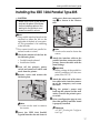
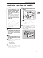
Installing the Paper Feed Unit Type305
Installing the Paper Feed Unit Type305
R CAUTION:
• It is recommended that at least
two persons are used to lift the
machine. Otherwise, the machine might fall and cause personal injury.
• When lifting the machine, use
the inset grips on both sides of
the machine. Otherwise, the machine might fall and cause personal injury.
•
• When moving the printer, be
sure to keep it level to avoid spilling the fuser oil. If oil is spilt, wipe
it with alkaline cleaner. Otherwise, the oily surfaces can create the danger of slipping and
personal injury.
Important
If
your printer is equipped with
❒
the optional tray, do not pull out
more than one tray with paper at a
time. If you do, the printer might
tilt forward.
Note
❒ It is impossible to install more than
two paper feed units to your printer at a time.
C Move the printer to make installing space.
2
TFWH100E
Important
❒ Be careful to lift the printer as
the right front side of the printer
is significantly heavier than the
left front side.
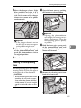
D Remove the paper feed unit from
the box, and remove the styrofoam packing and the bag from
the side covers.
TFWP050E
A Check the contents of the box for
the following items.
• Paper feed unit
• Installation Guide
B Turn
off the printer's power
switch and remove all cables and
cords from the printer.
19
Installing Options
E Remove both pieces of adhesive
tape.
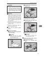
I Place
the printer on the paper
feed unit.
Align the printer onto the 4 upright pins on the paper feed unit
and then lower it gently.
2
TFWP060E
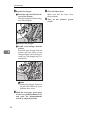
F Pull
out the paper tray, and remove the padding.
TFWP100E
J Connect all of cables that were removed in step B.
K Plug
the printer's power cord
back into the printer and the wall
socket. Turn on the printer's power switch.
TFWP070E
G Remove the ring attached to the
red tag.
firm that the paper feed unit is
properly installed.
Reference
⇒ P.107 “Printing the Configuration Page”
TFWP061E
H If installing two paper feed units,
place one paper feed unit on the
other paper feed unit at first. If installing only one paper feed unit,
go to step I.
Align the paper feed unit onto the
4 upright pins on the other paper
feed unit.
20
L Print a configuration page to con-
Note
❒ You can check if the paper feed
unit is installed properly by
checking the “Tray2” and
“Tray3” items of the “Printer Information” on the configuration
page.
❒ If the paper feed unit does not
work, follow the above instructions to reinstall it. If it still does
not work, contact your sales or
service representative.
Installing the Paper Feed Unit Type305
Important
❒ To make the printer recognize
the installed option properly,
you must set up the option with
the printer driver. Windows
95/98 ⇒ P.35 “Setting Up Options”, Windows 3.1x ⇒ P.38
“Setting Up Options”, Windows
NT4.0 ⇒ P.41 “Setting Up Options”
2
❒ After installing the paper feed
unit properly, set up the paper
size. ⇒ P.49 “Loading Paper”
21
Installing Options
2
22
3. Configuring the Printer for the
Network with the Operation Panel
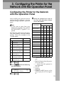
Configuring the Printer for the Network
with the Operation Panel
After installing the optional network
interface board, configure it for the
network using the printer's operation
panel.
Note
❒ If you want to print from your
Macintosh computer, the optional
RICOH-SCRIPT2 Type305 is required.
The following table shows the operation panel settings and their default
settings. These are included in the
”System Menu”.
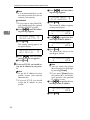
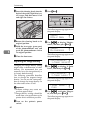
D Select
the protocol you want to
use. You can select one of items
on the table below.
Menu item on the Active Protocol
panel display
TCP *1 NW *2 ET *3 NB *4
All Active
(Default Setting)
'
'
Default
32 IP Address
011.022.033.044
33 Subnet Mask
000.000.000.000
34 Gateway Add
(Gateway Address)
000.000.000.000
35 Access CTL.
000.000.000.000
(Access Control Address)
36 Access Mask
(Access Control Mask)
000.000.000.000
37 Net Boot
(Network Boot)
None
38 Frame NW
(Frame type NetWare)
Auto Select
39 Active PTL.
(Active Protocol)
All Active
TCP/IP Only
NetWare Only
TCP & NetWare
'
'
'
'
'
TCP & EtherTalk
'
'
'
'
'
NetW & EtherTalk
TCP & NW & EtherTk
TCP & NetBEUI
TCP & NW & NB
'
NetW & NetBEUI
NW & ETK & NB
'
'
'
*1
j
l
'
'
'
'
'
• ' means that this protocol is active.
• Blank cell means that this protocol is not active.
• means that this protocol is
not supported.
*2
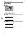
C Press {Enter}}.
'
NetBEUI Only
TCP & ETK & NB
message appears.
<Menu>
System Menu
'
ETalk & NetBEUI
A Press {Menu}}.
B Press {U}{T} until the following
None
EtherTalk Only
Items
'
*3
*4
TCP/IP
NetWare
EtherTalk
NetBEUI: NetBEUI appears on the
panel display, but it is not supported.
23
Configuring the Printer for the Network with the Operation Panel
Note
❒ It is recommended that you do
not select protocols that are not
used on your network.
Limitation
❒ If you want to select EtherTalk,
you should install the optional
RICOH-SCRIPT2 Type305.
A Press {U}{T} until the following message appears.
3
<System Menu> j
39.Active PTL. l
B Press {Enter}
}.
The current setting appears on
the panel display.
<Active PTL.>
*All Active
j
l
C Press {U}{T} until the protocol you want to use appears.
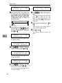
D Press {Enter}
}.
E If you use TCP/IP, you should assign the IP address to your printer.
Note
❒ To get the IP address for your
printer, contact your network
administrator.
❒ If you use TCP/IP, you should
assign the IP address to your
printer.
A Press {U}{T} until the following message appears.
<System Menu>
32.IP Address
j
l
B Press {Enter}
}.
The current IP address appears
on the panel display.
011.022.033.044
j
jl/#
C Use {U}{T} to specify the leftmost digit of the IP address.
111.022.033.044
j
jl/#
D Press {Enter}
}.
The pointer (U) moves to the
next digit as shown.
111.022.033.044
j
jl/#
Note
❒ You can return the pointer
(U) to the previous (left) digit
by pressing {Escape}.
❒ If you press {Escape} when
the pointer (U) is on the leftmost position, the specified
IP address is reset.
E Use {U}{T} to specify the second digit of the IP address.
191.022.033.044
j
jl/#
F Press {Enter}
}.
24
Configuring the Printer for the Network with the Operation Panel
G Repeat steps E and F to specify the rest digit of the IP address.
191.168.015.016
j
Check if the pointer (U) is at the
rightmost digit, press {Enter} to
register the IP address you specified.
<System Menu>
32.IP Address
j
l
F If you use TCP/IP, you should as-
sign “33.Subnet Mask”, “34. Gateway Add”, “35.Access CTL” and
“36.Access Mask” using the same
procedure for specifying the IP
address. ⇒ P.26 “Address”
G If
you use TCP/IP, you should
make settings for “37.Net Boot”.
You can select how to assign the
printer's address using the computer. Select one of items on the table below.
Menu item on Available method
the panel display
AR *1 RA *2 BO *3 DH *4
ARP+PING
'
ARP & RARP
'
ARP & BOOTP
'
APR & RARP & BOOT
'
'
'
'
'
None (Default Setting)
RARP+TFTP
'
'
BOOTP
RARP & BOOTP
*2
*3
*4
'
'
DHCP
*1
'
ARP+PING
RARP+TFTP
BOOTP
DHCP
Note
❒ You should set up your server,
if
you
want
to
use
“RARP+TFTP”, “BOOTP”, or
“DHCP”.
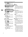
A Press {U}{T} until the following message appears.
<System Menu>
37.Net Boot
j
l
3
B Press {Enter}
}.
The current setting appears on
the panel display.
<Net Boot>
*None
j
l
C Press {U}{T} until the method
you want to use appears.
D Press {Enter}
}.
H If
you use NetWare, select the
frame type for NetWare.
Select one of items below if necessary.
• Auto Select (Default)
• Ethernet 802.3
• Ethernet 802.2
• Ethernet2
• Ethernet SNAP
Note
❒ Usually, use the default setting
(“Auto Select”). However if you
select “Auto Select”, the frame
type detected by the printer first
is adopted. If your network can
use more than two frame types,
the printer may fail to select the
correct frame type, if the “Auto
Select” is selected. In this case,
select the appropriate frame
type.
25
Configuring the Printer for the Network with the Operation Panel
A Press {U}{T} until the following message appears.
<System Menu>
38.Frame NW
j
l
B Press {Enter}
}.
The current setting appears on
the panel display.
<Frame NW>
*Auto Select
3
j
l
C Press {U}{T} until the frame
type you want to use appears.
D Press {Enter}
}.
E Press {On Line}
}.
I Reset
the printer to implement
the settings.
A Press {On Line}
} to enter the offline condition.
The On Line indicator turns off.
B Press {Reset}
}.
J Print
the configuration page to
check settings you have made.
A Press {Menu}
}.
B Press {U}{T} until the ”List
Print” appears.
C After confirming that “Config.Page” is on the display,
press {Enter}
}
D Press {Enter}
}.
The configuration page is now
printed. Check the contents of
the configuration page.
E Press {On Line}
}.
The normal display screen appears.
26
- Address
❖ Subnet Mask
A number used to mathematically
“mask” or hide the IP addresses on
the network by eliminating those
parts of the address that are alike
for all the machines on the network.
❖ Gateway Address
A gateway is a connection or interchange point that connects two
networks. A gateway address is for
the router or host computer used
as a gateway.
Note
❒ To get the addresses, contact
your network administrator.
❒ If you do not know the addresses, please use the default settings.
❖ Access Control Address and Access
Control Mask
Access Control Address and Access Control Mask are used to control the IP addresses that have
access to the computer used for
printing, with the IP address. If it is
not necessary for you to control the
access rights, select “0.0.0.0”.
Note
❒ When the Access Control Address settings coincide with the
masked result of the IP address
of the computer, print jobs from
that IP address can be accepted
by the network interface board.
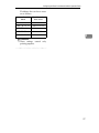
❒ For example, if you assign
192.168.15.16 as the Access Control Address to the network interface board, the combination
of the Access Control Mask and
Configuring the Printer for the Network with the Operation Panel
IP address that can have access
are as follows.
Access Control
Mask
IP Address that
have access
0.
0.
0.
0
xxx.xxx.xxx.xxx
255.
0.
0.
0
192.xxx.xxx.xxx
255.255.
0.
0
192.168.xxx.xxx
255.255.255.
0
192.168. 15.xxx
255.255.255.255
192.168. 15. 16
Limitation
❒ These settings control
printing requests.
3
only
27
Configuring the Printer for the Network with the Operation Panel
3
28
4. Installing the IPDL-C Printer
Driver
Before Installing the Printer Driver
To print, you must first install software called a printer driver on your computer.
The required printer driver is supplied on the CD-ROM that comes with your
printer.
Preparation
Set up the printer and connect it to your computer as described in the "Quick
Installation Guide". The procedures in this section assume that the printer is
connected to your printer by a parallel interface cable.
Important
❒ Some applications require their own specific settings, which may be different
from those provided by the printer driver. Be sure to check the documentation that comes with your applications for details.
❒ Considerable hard disk space is required on your computer for printing complex documents.
Note
❒ All of the procedures in this manual assume that you are familiar with general Windows procedures and practices. If you are not, see the documentation
that comes with Windows for details.
29
Installing the IPDL-C Printer Driver
Installing the Printer Drivers
Limitation
❒ The printer drivers supplied with this printer do not support operation under
a system running WindowsNT with a RISC based processor (MIPS R Series,
Alpha AXP, Power PC).
Note
❒ Recommended PC requirements.
• Memory: 32MB or more
• CPU: Pentium® 100MHz or more
• Free Hard disk space: 100MB or more
4
❖ Supported Operating Systems
• Microsoft Windows 95 operating system
• Microsoft Windows 98 operating system
• Microsoft Windows for Workgroups operating system 3.1x
• Microsoft Windows NT Server network operating system Version4.0
• Microsoft Windows NT Workstation operating system Version4.0
30
Windows 95/98 - Installing the IPDL-C Printer Driver
Windows 95/98 - Installing the IPDL-C
Printer Driver
Preparation
Before starting installation, be sure to carefully read the README file that is
on the CD-ROM containing the printer driver.
Important
❒ Never have two versions of the same printer driver installed on your system
at the same time. When upgrading to a new version of the printer driver, delete the old version, and then install the new one.
Normally you can use plug and play to install the printer driver. If your system
does not support plug and play, add the printer from the [Printers] window.
4
❖ Plug and Play
Plug and play automatically makes the required software settings whenever
it detects that a new peripheral device has been connected to the computer.
Plug and play operates when the following conditions are present.
• The computer supports plug and play (see the computer's documentation
for details).
• The printer is connected to the computer by a bi-directional interface cable.
• Printer power is turned on first, and then the computer is turned on.
❖ Printer Driver Installation
A Read the README file.
B Turn on the printer.
C Turn on the computer.
D Install the driver in accordance with the instructions that appear on your
computer screen.
• If the [New Hardware Found] dialog appears. ⇒ P.32 “Plug and Play Installation 1”
• If the [Device Driver Wizard] appears. ⇒ P.33 “Plug and Play Installation 2”
• If Windows 95/98 starts normally. ⇒ P.34 “Installing the Printer Driver
Without Using Plug and Play”
31
Installing the IPDL-C Printer Driver
Installing the Printer Driver Using Plug and Play
Preparation
Check to make sure that the printer is connected properly to your computer,
and that computer power is turned off.
A Turn on the printer's power switch.
B Turn on your computer.
Continue with one of the procedures below in accordance with what appears
on your computer's screen.
Note
❒ What happens after you turn on your computer depends on which version
of Windows 95/98 you are running and on your system setup.
4
❖ When the [New Hardware Found] dialog appears
The dialog indicates that plug and play is working. Continue with the procedure under P.32 “Plug and Play Installation 1”.
❖ When the [Device Driver Wizard] appears
This indicates that plug and play is working. Continue with the procedure
under P.33 “Plug and Play Installation 2” .
❖ When Windows 95/98 starts normally
This indicates that plug and play is not working. Continue with the procedure under P.34 “Installing the Printer Driver Without Using Plug and Play”.
Plug and Play Installation 1
Use the following procedure to install the printer when the [New Hardware Found]
dialog appears after you turn on the printer and then your computer.
A Insert the CD-ROM that comes with the printer, into your computer's CDROM drive.
B Click [Browse].
The Windows 95/98 printer driver is on the following directory on the CDROM: DRIVERS\IPDL_C\WIN95_98.
C Select the CD-ROM drive using the [Drives] list box.
D In the [Folders] box, double-click [DRIVERS], [IPDL_C] and then [WIN95_98]. Finally, click [OK].
32
Windows 95/98 - Installing the IPDL-C Printer Driver
E Click [OK].
The installer copies the printer driver files from the CD-ROM to your computer's hard disk.
F Restart Windows after completing the installation.
Important
❒ If your printer is equipped with certain options (ex. paper feed unit or
memory unit), you should set up the options with the printer driver. ⇒
P.35 “Setting Up Options”
Plug and Play Installation 2
Use the following procedure to install the printer when the [Device Driver Wizard]
appears after you turn on the printer and then your computer.
4
A Insert the CD-ROM that comes with the printer into your computer's CDROM drive, and then click [Next].
B Click [Finish].
C Change the name of the printer, if you want, and then click [Finish].
D If the next dialog appears, click [OK].
E If the next dialog asking you to specify the CD-ROM drive appears, select
the CD-ROM drive from the listbox. Finally, click [OK].
F Follow the instructions on the screen.
G Restart Windows after completing the installation.
Important
❒ If your printer is equipped with certain options (ex. paper feed unit or
memory unit), you should set up the options with the printer driver. ⇒
P.35 “Setting Up Options”
33
Installing the IPDL-C Printer Driver
Installing the Printer Driver Without Using Plug and Play
Turn on the printer and then your computer, and then use the following procedure to install the printer driver.
A Close all applications that are currently running.
B Click [Start], point to [Settings], and then click [Printers].
The [Printers] window appears.
C Double-click the [Add Printer] icon.
The [Add Printer Wizard] appears.
D Click [Next].
4
A dialog for specifying the port where the printer is connected appears.
E After confirming that the [Local Printer] option is selected, click [Next].
A dialog for selecting the printer manufacturer and model name appears.
F Click [Have Disk].
A dialog for driver installation from a disk appears.
G Insert the CD-ROM that comes with the printer into your computer's CDROM drive.
H Click [Browse].
The Windows 95/98 printer driver is on the following directory on the CDROM: DRIVERS\IPDL_C\WIN95_98.
I Use the [Drives] listbox to select the CD-ROM drive.
J In the [Folders] box, double-click [DRIVERS], [IPDL_C] and then [WIN95_98]. Finally , click [OK].
K Click [OK].
L Select the name of the printer whose driver you want to install by clicking
it, and then click [Next].
A port selection dialog appears.
M In the [Available Ports] box, select [Printer Port] by clicking it, and then click
[Next].
A dialog for changing the printer name appears.
N Change the name of the printer if you want, and then click [Next].
34
Windows 95/98 - Installing the IPDL-C Printer Driver
O Specify whether or not you want to print a test page, and then click [Finish].
The printer driver files are copied from the CD-ROM to your computer's hard
disk.
P If you are asked if you restart Windows, select [Yes]. If you are not asked,
restart Windows after completing the installation.
Q After Windows restarts, set up any options you have installed on the printer.
Reference
⇒ P.35 “Setting Up Options”
Setting Up Options
4
Note
❒ When setting up options, you should access the [Installable Options] dialog
from Windows. You cannot set up options when accessing the [Installable Options] dialog from an application.
A Click [Start], point to [Settings], and then click [Printers].
The [Printers] window appears.
B Select the icon of the printer you want to use by clicking it. On the [File]
menu, click [Properties].
C Click [Setup] tab, and then click [Installable Options].
The [Installable Options] dialog appears.
D Use the [Option Tray] listbox to specify the optional tray unit.
Specifying the wrong tray here will make it impossible to use your tray correctly.
E Use the [Total Printer Memory] listbox to specify how much memory is in-
stalled on the printer.
Specifying the wrong amount of memory here may cause printing problems.
Be sure to change this setting whenever you add more memory.
Reference
You can find out how much memory is currently stored in memory by
printing a Configuration Page on the printer. ⇒ P.107 “Printing the Configuration Page”
F Click [OK] to close the dialog.
G Click [OK] to close the printer's Properties dialog.
35
Installing the IPDL-C Printer Driver
Canceling a Print Job
A Double-click the printer icon on the Windows Task Bar.
This opens a window that shows all the print jobs that are currently queued
for printing. Check the current status of the job you want to cancel.
B Select the name of the job you want to cancel by clicking it.
C On the [Document] menu, click [Cancel Printing].
Note
❒ You can also open the print job queue window by double-clicking the
printer icon in the [Printers] window.
4
D Make sure that the printer's On Line indicator is lit, press the printer's {Re-
set}
} key.
The message appears on the operation panel display indicating that the print
job is being cancelled.
Important
❒ The above procedure cancels the print job that is currently being processed
by the printer. In some cases, the printer may already be processing data
for the next print job following the one currently being output. In such a
case, the next print job is also canceled when you press {Reset}.
❒ When your printer is being shared by multiple computers, be careful you
don't accidentally cancel someone else's print job.
Note
❒ You cannot stop printing data that has already been processed internally
by the printer. Because of this, printing may continue for a few pages after
you press {Reset}.
❒ A print job that contains a large volume of data may take a considerable
time to stop.
36
Windows 3.1x - Installing the IPDL-C Printer Driver
Windows 3.1x - Installing the IPDL-C Printer
Driver
Preparation
Before starting installation, be sure to carefully read the README file that is
on the CD-ROM containing the printer driver.
Important
❒ Never have two versions of the same printer driver installed on your system
at the same time. When upgrading to a new version of the printer driver, delete the old version, and then install the new one.
4
Installing the Printer Driver
A From the Program Manager [Main] group, open the [Control Panel] and double-click the Printers icon.
The [Printers] dialog appears.
B Click [Add] to expand the dialog and display the [List of Printers].
If there are no printers installed on your computer, the [List of Printers] appears
automatically when you display the [Printers] dialog, and the [Add] button is
grayed out. If this is the case, perform the next step, below.
C In the [List of Printers], select [Install Unlisted or Updated Printer] by clicking it,
and then click [Install…].
The [Install Drivers] dialog appears.
D Insert the CD-ROM that comes with the printer into your computer's CDROM drive.
E Click [Browse…].
The Windows 3.1x printer driver is on the following directory on the CDROM: DRIVERS\IPDL_C\WIN31.
F Use the [Drives] listbox to select the CD-ROM drive.
G In the [Directories] box, double-click [DRIVERS], [IPDL_C] and then [WIN31]. Finally click [OK].
H Click [OK].
I In the [List of Printers] box, select the name of the printer whose driver you
want to install by clicking it, and then click [OK].
The printer driver files are copied from the CD-ROM to your computer's hard
disk. After installation is complete, click [Close] to close the [Printers] dialog.
37
Installing the IPDL-C Printer Driver
J After installation is complete, click [Close] to close the [Printers] dialog.
K Restart Windows.
L After Windows restarts, setup any options you have installed on the printer.
Reference
⇒ P.38 “Setting Up Options”
Setting Up Options
Note
❒ When setting up options, you should access the [Installable Options] dialog
from Windows. You cannot set up options when accessing the [Installable Options] dialog from an application.
4
A From the Program Manager [Main] group, open the [Control Panel] and double-click the [Printers] icon.
The [Printers] dialog appears.
B In the [Installed Printers] box, select the name of the printer you want to use
by clicking it, and then click [Setup…].
A dialog for making printer driver settings appears.
C Click [Setup] tab, and then click [Installable Options].
The [Installable Options] dialog appears.
D Use the [Option Tray] listbox to specify the optional tray unit.
Specifying the wrong tray here will make it impossible to use your tray correctly.
E Use the [Total Printer Memory] listbox to specify how much memory is in-
stalled on the printer.
Specifying the wrong amount of memory here may cause printing problems.
Be sure to change this setting whenever you add more memory.
Reference
You can find out how much memory is currently stored in memory by
printing Configuration Page on the printer. ⇒ P.107 “Printing the Configuration Page”
F Click [OK] to close the dialog.
G Click [OK] to close the dialog.
H Click [Close] to close the [Printers] dialog.
38
Windows 3.1x - Installing the IPDL-C Printer Driver
Canceling a Print Job
A In the [Main] group, double-click the [Print Manager] icon.
A window that shows all the print jobs that are currently queued for printing
appears.
B Select the name of the job you want to cancel by clicking it.
C On the [Document] menu, click [Delete Document].
D Click [Close] to close the dialog.
E Make sure that the printer's On Line indicator is lit, press the printer's {Re-
set}
} key.
The message appears on the operation panel display indicating that the print
job is being cancelled.
4
Important
❒ The above procedure cancels the print job that is currently being processed
by the printer. In some cases, the printer may already be processing data
for the next print job following the one currently being output. In such a
case, the next print job is also canceled when you press {Reset}.
❒ When your printer is being shared by multiple computers, be careful you
don't accidentally cancels someone else's print job.
Note
❒ You cannot stop printing data that has already been processed internally
by the printer. Because of this, printing may continue for a few pages after
you press {Reset}.
❒ A print job that contains a large volume of data may take a considerable
time to stop.
39
Installing the IPDL-C Printer Driver
Windows NT4.0 - Installing the IPDL-C
Printer Driver
Preparation
Before starting installation, be sure to carefully read the README file that is
on the CD-ROM containing the printer driver.
Important
❒ Never have two versions of the same printer driver installed on your system
at the same time. When upgrading to a new version of the printer driver, delete the old version, and then install the new one.
Limitation
❒ Printer driver installation requires full control access right. To install the
printer driver, log on as an Administrators or a Power Users group member.
4
Installing the Printer Driver
A Click [Start], point to [Settings], and then click [Printers].
The [Printers] window appears.
B Double-click the [Add Printer] icon.
The [Add Printer Wizard] appears.
C After confirming that [My Computer] option is selected, click [Next].
A dialog for specifying the port where the printer is connected appears.
D Click a check box to select the port you want to use, and click [Next].
A dialog for the manufacturer and model of the printer appears.
E Click [Have Disk…].
A dialog for driver installation from a disk appears.
F Insert the CD-ROM that comes with the printer into your computer's CDROM drive.
G Change the drive name in the listbox to the name of the CD-ROM drive,
and then click [Browse…].
The Windows NT4.0 printer driver is on the following directory on the CDROM: DRIVERS\IPDL_C\NT4.
H Double-click [DRIVERS], [IPDL_C] and then [NT4]. Finally, click [Open].
I Click [OK].
A printer model selection dialog appears.
40
Windows NT4.0 - Installing the IPDL-C Printer Driver
J Select the name of the printer whose driver you want to install by clicking
it, and then click [Next].
A dialog for changing the printer name appears.
K Change the name of the printer if you want, and then click [Next].
L If the printer is to be shared over a network, click [Shared] to select it.
Selecting [Shared] causes the computer you are on to operate as the printer
server. If you select [Not shared] here, skip step M.
M In the [Shared Name] box, type in the name that printer should use on the net-
work.
The initial default Shared name is the same name as the Name box in step K,
above. You can leave this name as it is, or change to a different one.
4
N Click [Next].
O Specify whether or not you want to print a test page, and then click [Finish].
The printer driver files are copied from the CD-ROM to your computer's hard
disk.
After installation is complete, the [Printers] window appears with the icon of
the newly installed printer.
P Restart Windows.
Q After Windows restarts, set up any options you have installed on the printer.
Reference
⇒ P.41 “Setting Up Options”
Setting Up Options
A Click [Start], point to [Settings], and then click [Printers].
The [Printers] window appears.
B Select the icon of the printer you want to use by clicking it. On the [File]
menu, click [Properties] .
C Click the [Installable Options] tab.
D Use the [Option Tray] listbox to specify the optional tray unit.
Specifying the wrong tray here will make it impossible to use your tray correctly.
41
Installing the IPDL-C Printer Driver
E Use the [Total Printer Memory] listbox to specify how much memory is in-
stalled on the printer.
Specifying the wrong amount of memory here may cause printing problems.
Be sure to change this setting whenever you add more memory.
Reference
You can find out how much memory is currently stored in memory by
printing a Configuration Page the printer. ⇒ P.107 “Printing the Configuration Page”
F Click [OK] to close the printer properties.
Canceling a Print Job
4
A Double-click the printer icon on the Windows Task Bar.
A window that shows all the print jobs that currently queued for printing appears. Check the current status of the job you want to cancel.
B Select the name of the job you want to cancel by clicking it.
C On the [Document] menu, click [Cancel Printing].
Note
❒ You can also open the print job queue window by double-clicking the
printer icon in the [Printers] window.
D Make sure that the printer's On Line indicator is lit, press the printer's {Reset}
}key.
E The message appears on the operation panel display indicating that the
print job is being cancelled.
Important
❒ The above procedure cancels the print job that is currently being processed
by the printer. In some cases, the printer may already be processing data
for the next print job following the one currently being output. In such a
case, the next print job is also canceled when you press {Reset}.
❒ When your printer is being shared by multiple computers, be careful you
don't accidentally cancels someone else's print job.
Note
❒ You cannot stop printing data that has already been processed internally
by the printer. Because of this, printing may continue for a few pages after
you press {Reset}.
❒ A print job that contains a large volume of data may take a considerable
time to stop.
42
5. Paper and Other Media
Paper and Other Media Supported by this
Printer
Paper Types and Sizes
This section provides the type, size, feed direction, and maximum capacity of
paper that can be loaded into each paper tray in this printer.
Note
❒ The ”K” symbol means short-edge feed direction.
❒ The ”L” symbol means long-edge feed direction.
❒ The paper feed direction depends on the paper size.
Size (mm)
A3
K
297 × 420
✩
❍
❍
B4 JIS
K
257 × 364
✩
★
★
A4
K
210 × 297
×
×
×
L
297 × 210
✩
❍
❍
K
182 × 257
×
×
×
L
257 × 182
✩
★
★
K
148 × 210
×
×
×
L
210 × 148
✩
★
×
B6 JIS
K
128 × 182
✩
×
×
A6
K
105 × 148
✩
×
×
Double Letter
K
279 × 432
✩
❍
❍
K
216 × 356
✩
❍
❍
B5 JIS
A5
Bypass Tray
Feed direction
Paper Feed Unit
Type305 (Tray2/3)
Standard Tray (Tray1)
❖ Paper Sizes
(DLT, 11" × 17")
Legal (LG, 81/2" × 14")
43
Size (mm)
K
216 × 279
×
×
×
L
279 × 216
✩
❍
❍
L
140 × 216
✩
★
×
K
184 × 276
×
×
×
L
276 × 184
✩
❍
❍
Folio (81/4" × 13")
K
210 × 330
✩
★
★
Foolscap (F4, 81/2" × 13")
K
216 × 330
✩
★
★
F/GL (8" × 13")
K
203 × 330
✩
★
★
Custom Size
—
—
✩
×
×
Letter (LT, 81/2" × 11")
Half Letter
Bypass Tray
Feed direction
Paper Feed Unit
Type305 (Tray2/3)
Standard Tray (Tray1)
Paper and Other Media
(HLT, 51/2" × 81/2")
Executive
(Exec.,
5
71/
4"
×
101/
2")
• ✩ means that the size is supported and needs to specify the paper size using
the operation panel. (Regarding the bypass tray, there is no dial on the tray.)
⇒ P.52 “Loading Paper in the Bypass Tray”
• ❍ means that the size is supported and indicated on the tray dial. Be sure to
set the paper size dial to match the actual paper size loaded in the tray.
• ★ means that the size is supported but not indicated on the paper size dial.
You should set the paper size dial to “p”, and specify the paper size using
the operation panel. The default setting is Foolscap (8.5“×13”). ⇒ P.51 “Specifying paper size using the operation panel”
• × means that the size is not supported.
The paper tray can support paper 64 – 105 g/m2 (17 – 28 lb).
The bypass tray can support paper 64 – 157 g/m2 (17 – 42 lb).
The optional paper tray can support paper 64 – 105 g/m2 (17 – 28 lb).
44
Paper and Other Media Supported by this Printer
Precautions for Paper
Note the following precautions when handling or selecting paper to be used
with this printer.
Cautions in loading paper
Important
❒ Do not use paper that is meant for an inkjet printer. Otherwise, it may stick to
the fusing unit and cause a paper misfeed.
❒ When printing on an OHP transparency that has a print side, load it with the
print side down onto the bypass tray. Otherwise, it may stick to the fusing
unit and cause a misfeed.
• Use only the recommended paper types. Print quality cannot be guaranteed
if other paper types are used. ⇒ P.47 “Paper not supported by this printer”
• Do not use paper that is already printed on.
5
Cautions in storing paper
Paper should always be stored properly. Improperly stored paper might result
in poor print quality, paper misfeeds, or printer damage.
Follow the precautions below.
• Avoid storing paper in humid areas.
• Avoid exposing paper to direct sunlight.
• Store on a flat surface.
• Keep open reams of paper in the package in which the paper came.
Paper types and cautions
❖ Plain paper
• The standard tray can hold up to 250 sheets. *1
• The bypass tray can hold up to 50 sheets. *1
• The Paper Feed Unit Type305 (option) can hold up to 500 sheets. *1
*1
: Based on paper that is 80 g/m2 (metric version), 20 lb (inch version) in weight.
• If paper is curled or bent, correct it before loading.
45
Paper and Other Media
❖ Thick Paper
• If you print on paper heavier than 105 g/m2 (28 lb), use the bypass tray.
The bypass tray can hold paper up to 157 g/m 2 (42 lb) in weight. The print
quality on paper that is thicker cannot be guaranteed.
• The bypass tray can hold up to 25 sheets.
Note
❒ The number of sheets to be set may vary depending on the paper thickness and paper type.
• When printing on thick paper, you should select the thick paper mode
with the printer driver.
❖ Adhesive labels
• When printing on adhesive labels, use the bypass tray.
5
TFWY060E
• Load adhesive labels into the tray with the print side down.
• Remove any unused adhesive labels from the tray after you are finished
printing. Leaving them in the tray can cause them to curl.
• When printing on adhesive labels, you should select the plain paper mode
with the printer driver.
• The bypass tray can hold up to 40 adhesive labels.
Note
❒ The number of sheets to be set may vary depending on the paper thickness and paper type.
46
Paper and Other Media Supported by this Printer
❖ OHP transparencies
• When printing on OHP transparency, use the bypass tray.
TFWY060E
• Load OHP transparencies into the tray with the print side down. Otherwise, it may stick to the fusing unit and cause a misfeed.
• Remove any unused OHP transparencies from the tray after you are finished printing. Leaving them in the tray can cause them to curl.
• When printing on OHP transparencies, you should select the OHP transparency mode with the printer driver.
• The bypass tray can hold up to 50 OHP transparency sheets.
5
Note
❒ The number of sheets to be set may vary depending on the paper thickness and paper type.
• When the “OHP Slip” settings is set to “Off” (⇒ P.106 “11. OHP Slip”), be
sure to remove each OHP transparency immediately after it is printed.
Note
❒ If the direction and size of paper loaded in the paper tray is different
from the direction and size of the OHP transparency, “OHP Slip” will
not work even if “OHP Slip” settings is set to “On”. Be sure to remove
each OHP transparency immediately after it is printed.
Paper not supported by this printer
Avoid using the following types of paper that are not supported by this printer:
• Paper whose weight is heavier or lighter than the limitation.
• Bent, folded, or creased paper
• Curled or twisted paper
• Torn paper
• Wrinkled paper
• Damp paper
• Paper stuck together
• Paper that is dry enough to emit static electricity
47
Paper and Other Media
• Paper that has already been printed on (with the exception of preprinted letterhead)
Note
❒ The ink for the format printing by a copier, or an inkjet printer and so on
might do harm to the fusing unit of this printer due to a difference in fusing
temperatures.
• Coated paper (except the recommended one)
• Special paper like thermal paper, aluminum foil, carbon paper and conductive paper
• Heavily textured paper
• Glued paper
• Label paper on which glue or base paper is exposed
• Paper with clips or stapled
• Paper with tape or ribbons attached
• Paper is meant for an inkjet printer.
• Envelopes
5
Printable Area
The following shows the printable area for this printer. Be sure to set the print
margins correctly.
Feed direction
4.3mm(1/6")
4.3mm(1/6")
4.3mm(1/6")
printable area
4.3mm(1/6")
Note
❒ The printable area may vary depending on paper size, printer language and
printer driver settings.
48
Loading Paper
Loading Paper
Loading Paper in the Paper
Tray
Use the following procedure to load
paper in the paper tray and optional
tray. See P.52 “Loading Paper in the Bypass Tray” for details on the bypass
tray.
B Slide
the paper guides to positions that match the size of paper
you want to load.
Adjust the paper guides until they
click into position.
Important
❒ After you load paper, you must set
the paper size dial to match the actual paper size loaded in the tray.
Otherwise, the printer might be
damaged.
Reference
See P.43 “Paper and Other Media
Supported by this Printer” for details
on supported paper types and sizes.
A Carefully pull the paper tray out
of the printer and place it on a flat
surface.
5
TFWY100E
Important
❒ Do not touch the friction pad
(A). Otherwise, paper misfeeds
or paper multi-feeds might occur .
C Load paper into the tray with the
print side up.
TFWY110E
TFWY090E
Important
❒ Make sure that the stack of paper is no higher than the limit
mark (TT) inside the tray.
❒ Make sure the paper fits under
the back paper guide.
49
Paper and Other Media
D Adjust
the paper size dial to
match the size of the paper in the
paper tray.
Important
❒ When loading B4 JISK, B5
JISL, A5L, 51/2"×81/2"L,
8"×13”K, 81/4"×13"K or 81/2"
×13"K in the paper tray, set the
dial to “p” and specify the paper size using the operation
panel. ⇒ P.51 “Specifying paper
size using the operation panel”
E Slide
the paper tray completely
into the printer.
TFWY120E
Note
❒ The following table shows the
position of the paper size dial.
5
Paper Size
Standard
Tray
(Tray1)
Optional
Tray
(Tray2/3)
A3
A3K
A3K
A4
A4L
A4L
A5
p
—
B4
p
p
B5
p
p
Double Letter
(11"×17")
11×17
11×17
Legal
(81/2"×14")
81/2×14
81/2×14
Letter
(8 /2"×11")
81/2×11
81/2×11
Half Letter
(51/2"×81/2")
p
—
1
Executive 71/4"×101/2" 71/4"×101/2"
(71/4"×101/2")
50
F
(8"×13")
p
p
Folio
(81/4"×13")
p
p
Foolscap
(81/2"×13")
p
p
Important
❒ Be sure to insert the paper tray
completely. Otherwise, paper
misfeeds might occur.
Loading Paper
<Tray Size[*]> j
*8.5x13
l
Specifying paper size using the
operation panel
Use the following procedure to specify the paper size from the printer's
operation panel after loading paper
with mark “p” in the table mentioned above into tray 1, tray 2 and
tray 3.
A Press {Menu}}.
{U}{T} to select the paper
size you have specified for the paper tray, and then press {Enter}
}.
<Tray Size[*]> j
8.25x13
l
E Press {On Line}}.
On Line
Menu
Power
D Use
Error
Reset
The normal display screen appears.
Escape
Media
Enter
IPDL-C
Ready
Data In
5
TFWS020E
The following message appears on
the panel display.
<Menu>
IPDL-C Menu
j
l
F Press {On Line}} to enter
the offline condition.
The On Line indicator turns off.
G Press {Reset}}.
B Use
{U}{T} to display “System
Menu”, and then press {Enter}
}.
<Menu>
System Menu
j
l
The following message appears on
the panel display.
<System Menu>
1.Paper Tray
j
l
C Use
{U}{T} to display “2.Tray
Size[p
}.
p]”, and then press {Enter}
<System Menu> j
2.Tray Size[*]l
The currently selected paper size
appears on the panel display.
51
Paper and Other Media
Loading Paper in the Bypass
Tray
Note
❒ Slide out the bypass tray extender.
Note
❒ Do not open the front cover when
loading paper into the bypass tray.
Reference
⇒ P.43 “Paper Types and Sizes”
⇒ P.45 “Precautions for Paper”
TFWY150E
Loading paper
C Load paper until it stops with the
A Open the bypass tray.
print side down.
5
TFWY160E
TFWY130E
B Slide the side guides.
Important
❒ Make sure the paper fits under
the side guides.
❒ The side guides should be set to
the correct paper size to avoid
paper feed problems.
❒ Do not load paper when printing.
TFWY140E
52
Loading Paper
E Select
the paper size you have
specified for the paper tray.
Specifying paper size using the
operation panel
Use the following procedure to specify the paper size from the printer's
operation panel after loading paper
into the bypass tray.
A Press {Media}}.
On Line
Menu
Power
Reset
<Media>
2.Paper Size
Enter
Data In
TFWS040E
The following message appears on
the panel display.
<Media>
1.Paper Tray
j
l
B After
confirming that “1.Paper
Tray” is on the display, press {Enter}
}.
<Paper Tray>
*Tray1/A4
j
l
C Use
{U}{T} to display “Byps.”,
and then press {Enter}
}.
Note
❒ If there is no paper in the bypass
tray, the Error indicator stays
on.
D Use {U}{T} to display “2. Paper
Size”, and then press {Enter}
}.
The current paper size appears on
the panel display.
<Paper Size>
A3
A Use {U}{T} to display the paper size that is in the tray, and
then press {Enter}
}.
The following message appears
on the panel display.
Escape
Media
Error
Standard Paper Size
j
l
j
l
Custom Size Paper
5
A Use {U}{T} to display “Custom”, and then press {Enter}
}.
The following message appears
on the panel display.
<Custom>
l
jl/# Width 297mm
B Use {U}{T} to change the third
(leftmost) digit of the paper
width, and then press {Enter}
}.
The pointer (l) moves to the
right.
<Custom>
l
jl/# Width 197mm
Note
❒ Press {Escape} to move the
pointer to the left.
❒ Press {Escape} while the
pointer is located at the leftmost digit of the width to
cancel the settings and return
to step D.
53
Paper and Other Media
C Repeat step B to set the value
of the width.
While the pointer is located at
the first (rightmost) digit of the
width, press {Enter} to advance
to the length setup display.
Note
❒ Press {Escape} while the
pointer is located at the leftmost digit of the width to return to the width setup
display.
Sliding out the Output Tray
Extender
If you load paper of A4L or 81/2" ×
11"L or larger, slide out the output
tray extender.
Important
❒ Do not place the rear end of the
printer near a wall or touch it with
barehands. This area can become
extremely hot.
D Repeat steps B and C to set
the value of the length.
While the pointer is located at
the first (rightmost) digit of the
length, press {Enter} to return to
“Media”.
5
<Media>
2.Paper Size
j
l
E Press {Escape}
}.
The normal display screen appears.
IPDL-C
Ready
54
TFWX440E
Note
❒ After printing, return the output
tray extender to its original position.
6. Troubleshooting
Error & Status Messages
There are three types of error messages:
• Printed error message
• Displayed error message
• Getting Printer Information over the Network
Printed Error Message
The error message shown below is output by the printer whenever there is not
enough memory to print your data.
Error Message
Required Action
There is not enough memory in your
printer to print this page. Change the resolution to 300 dpi in the printer driver and
try again. For details, please refer to the
troubleshooting section in your manual.
The following are the actions you should
take when you encounter memory shortage problems. If these actions do not solve
the problem individually, try them in
combination with each other. ⇒ P.114
“Low Memory”
A Increase printer memory.
Install the optional memory unit to increase printer memory capacity. ⇒
P.11 “Installing the Memory Unit
(SIMM)”
B Change the Color Level to [1 bit].
Use the printer driver to select [Fast] or
change the Color Level to [1 bit].
⇒ The printer driver online help
⇒ "RICOH-SCRIPT2 Operating Instructions”
C Reduce resolution.
Use the printer driver to set resolution
to 300 dpi.
⇒ The printer driver online help
⇒ "RICOH-SCRIPT2 Operating Instructions”
D Turn on "Image Memory".
Use the printer's "System Menu" to
turn on "Image Memory". ⇒ P.95
“Making Printer Settings with the Operation Panel”
55
Troubleshooting
Error & Status Messages on the Operation Panel
Note
❒ The panel display can show only one error message at a time. Printing a configuration page shows all current printer errors under the Printer Error item
of the Printer Information section. ⇒ P.107 “Printing the Configuration Page”
Message
Add FuserOil
(on the upper line)
Add FuserOil
(on the lower line)
Add Toner
xxx
6
Description
The fuser oil bottle is emp- Replace the fuser oil bottle.
ty.
⇒ P.90 “Replacing the Fuser
Oil Bottle and Ozone Filter”
Fuser oil is low. You can
print about 200 or /more
pages after this message
appears.
Replace the fuser oil bottle.
⇒ P.90 “Replacing the Fuser
Oil Bottle and Ozone Filter”
Indicated toner is low or
runs out.
Replace the indicated toner
cartridge. ⇒ P.85 “Replacing the Toner Cartridge”
Change Fuser
The fusing unit is at the end Contact your sales or serof its service life.
vice representative.
Change PCU
The photoconductor unit is If printed side gets dirty,
nearly at the end of its life. replace the photoconductor unit. ⇒ P.88 “Replacing
the Photoconductor Unit”
Close Front Cover
The front cover is open.
Close the front cover. (⇒
P.1)
Close Left Cover
The left cover is open.
Close the left cover. (⇒ P.1)
Close Paper Exit
The paper exit cover is
open.
Close the paper exit cover.
(⇒ P.3)
Cover
Load
(paper size)
There is no indicated paper Load the indicated paper
size in the paper tray being size into the paper tray beused.
ing used. ⇒ P.49 “Loading
Paper”
There is no correct paper
size in the paper tray.
Load (paper size)
Press # key
Open Front Cover
Remove Misfeed
56
Comments
Load the correct paper size.
There is no indicated paper Load the indicated paper
size in any paper tray.
size into the bypass tray,
and press {Enter} to resume printing.
There is a paper misfeed in Remove the misfed paper.
the printer.
⇒ P.76 “Removing Misfed
Paper”
Error & Status Messages
Message
Description
Comments
Paper Size Error
There is a difference between the paper size in the
tray and the requested paper size from the computer.
After confirming that the
size, feed direction of paper
and the paper size dial in
the tray are set correctly,
open and close the front
cover. ⇒ P.49 “Loading Paper in the Paper Tray”
Power Off/On
There is a malfunction in
the printer.
Turn the printer off and on.
SC:xxx
Remove Misfeed
From Output Tray
Remove Misfeed
From Tray #
Reset Charger
Correctly
Reset Fusing
Unit Correctly
Reset PCU
Correctly
Reset Toner
Correctly
Reset Tray
Correctly
Reset Waste T
Bottle Correctly
If this doesn't clear the
problem, contact your sales
or service representative.
There is a paper misfeed in Remove the misfed paper.
the printer.
⇒ P.76 “Removing Misfed
Paper”
There is a paper misfeed in Remove the misfed paper.
the printer.
⇒ P.76 “Removing Misfed
Paper”
The charger is not set cor- Set the charger correctly. ⇒
rectly or the charger clean- P.92 “Replacing the Waste
er is not in the correct
Toner Bottle and Charger”
position.
The fusing unit is not installed in the printer.
6
Contact your sales or service representative.
The photoconductor unit is Install the photoconductor
not installed in the printer. unit. ⇒ P.88 “Replacing the
Photoconductor Unit”
The toner cartridge is not
installed correctly.
Install the cartridge correctly. ⇒ P.85 “Replacing
the Toner Cartridge”
The paper tray is not installed correctly.
Install the paper tray correctly.
The tray on the paper feeding path was not set correctly when the printer
received the print job.
Install the paper tray correctly. The printer will restart printing automatically.
The waste toner bottle is
not installed.
Install the waste toner bottle. ⇒ P.92 “Replacing the
Waste Toner Bottle and
Charger”
57
Troubleshooting
Message
Warming Up
Waste T Full
(on the lower line)
Waste Toner is
Full
A3:Error
Description
Comments
The printer is preparing for Wait until the printer is
printing.
warmed up.
The printer adjusts itself
regularly to maintain print
quality. (This message
might appear while printing.)
It is not an error message.
The waste toner bottle is
nearly full.
Replace the waste toner
bottle. ⇒ P.92 “Replacing
the Waste Toner Bottle and
Charger”
The waste toner bottle is
full.
Replace the waste toner
bottle. ⇒ P.92 “Replacing
the Waste Toner Bottle and
Charger”
Ther is too much data for
the I/O buffer to handle.
Check if the interface cable
is inserted into the printer
and your computer securely.
6
The printer is working
properly. Just wait a while.
Check if the interface cable
is not damaged or broken.
Increase the size of I/O
buffer. ⇒ P.103 “System
Menu”
A6:Error
There is not enough printer See P.114 “Low Memory”.
memory to print one or
more of the pages in the
print job.
AB:Error
The printer is unable to
process the data you are
trying to print.
Install an optional memory
units (SIMM) to increase
printer memory capacity.
Reduce the amount of data
being sent to the printer.
58
Error & Status Messages
Message
B0:Error
Description
Comments
An error has occurred in
the optional memory unit.
(SIMM)
Turn the printer's power
switch off and on. Then, try
to print again.
Turn off the printer's power switch. Reinstall the
memory unit and turn on
the printer's power switch.
Then, try to print again.
Turn off the printer's power switch. Remove the
memory unit and turn on
the printer's power switch.
Then, try to print again.
Note
❒ If you remove the memory unit, you must set
up the option with the
printer driver. Windows 95/98 ⇒ P.35
“Setting Up Options”,
Windows 3.1x ⇒ P.38
“Setting Up Options”,
Windows NT4.0 ⇒ P.41
“Setting Up Options”.
6
❒ In this case, you might
not be able print complex print jobs.
B1:Error
An error has occurred in
Contact your sales or serthe standard parallel inter- vice representative.
face.
B3:Error
The printer setting is
wrong.
Reset the printer using
"Menu Reset" of the "Maintenance" menu. ⇒ P.95
“Making Printer Settings
with the Operation Panel”
B5:Error
An error has occurred in
the optional RICOHSCRIPT2 module.
Remove the RICOHSCRIPT2 module from the
printer and turn off and on
the printer's power switch.
Then, try to print again.
59
Troubleshooting
Message
Description
Comments
B6:Error
An error has occurred in
the optional parallel interface board.
Turn off the printer's power switch. Remove and reinstall the optional parallel
interface board and turn on
the printer's power switch.
Then, try to print again.
B7: Error
An error has occurred in
Turn the printer's power
the optional network inter- switch off and on. Then, try
face board.
to print again.
Turn off the printer's power switch. Reinstall the network interface board and
turn on the printer's power
switch. Then, try to print
again.
Turn off the printer's power switch. Remove the network interface board from
the printer and turn on the
printer's power switch.
Then, try to print again.
6
Note
❒ If you remove the network interface board,
you cannot perform
your print job over the
network. You can send
your print job to the
printer only via a parallel cable connection.
85:Error
An error has occurred in
the printer's standard
memory.
Turn off and on the printer's power switch.
86:Error
You may be trying to print
with the wrong printer
driver.
Make sure you are using
the correct printer driver.
You might not use the correct interface cable.
Make sure you are using
the correct interface cable.
An error has occurred in
the printer's standard
memory.
Turn off and on the printer's power switch.
91:Error
60
Error & Status Messages
Message
94:Error
Description
Comments
The amount of the memory Specify the correct memory
is not set correctly.
capacity using the printer
driver. Windows 95/98 ⇒
P.35 “Setting Up Options”,
Windows 3.1x ⇒ P.38 “Setting Up Options”, Windows
NT4.0 ⇒ P.41 “Setting Up
Options”
Note
❒ If you cannot solve the problem by taking above actions, turn the printer
power off and then back on again. If this does not clear the error message,
write down the error number and the message, and contact your sales or service representative.
Getting Printer Information over the Network
Note
❒ The optional network interface board is required to get the information over
the network
6
Printer Current Status
You can check the printer's current status using the following method.
❖ UNIX
Use the lpq command or stat parameter of rsh, rcp, or ftp.
❖ mshell
Use status command.
Message
Description
Comments
Ready
Printer works properly.
—
Add Fuser Oil
The fuser oil bottle is emp- Replace the fuser oil bottle.
ty.
⇒ P.90 “Replacing the Fuser
Oil Bottle and Ozone Filter”
Call Service
There is malfunction in the Turn the printer off and
printer.
then on.
If this doesn't clear the
problem, contact your sales
or service representative.
Change Fusing Unit
The fusing unit is at the end Contact your sales or serof its life.
vice representative.
61
Troubleshooting
Message
6
62
Description
Comments
Change PCU
The photoconductor unit is If printed side gets dirty,
nearly at the end of its life. replace the photoconductor unit. ⇒ P.88 “Replacing
the Photoconductor Unit”
Close Front Cover
The front cover is open.
Close the front cover. (⇒
P.1)
Close Left Cover
The left cover is open.
Close the left cover. (⇒ P.1)
Close Paper Exit Cover
The paper exit cover is
open.
Close the paper exit cover.
(⇒ P.3)
Energy Save Mode
The printer is in Energy
Saver mode.
Wait for a while.
Error: Power Off/On
There is malfunction in the Turn the printer off and on.
printer.
Fuser Oil is Low
Fuser oil is low. You can
Replace the fuser oil bottle.
print about 200 pages more ⇒ P.90 “Replacing the Fuser
after this message appears. Oil Bottle and Ozone Filter”
Load Paper
There is no paper of the in- Load paper of the indicated
dicated paper size in the
paper size into the paper
paper tray being used.
tray being used.
Misfeed: Front Cover
There is a paper misfeed in Remove the misfed paper.
the printer.
⇒ P.76 “Removing Misfed
Paper”
Misfeed: Output Tray
There is a paper misfed in
the printer.
Remove the misfeed paper.
⇒ P.76 “Removing Misfed
Paper”
Misfeed: Paper Tray
There is a paper misfed in
the printer.
Remove the misfeed paper.
⇒ P.76 “Removing Misfed
Paper”
Paper Size Error
There is a difference between the paper size in the
tray and the requested paper size from the computer.
After confirming that the
size, feed direction of paper
and the paper size dial in
the tray are set correctly,
open and close the front
cover. ⇒ P.49 “Loading Paper in the Paper Tray”
Please Wait
The printer is now preparing for printing.
Wait for a while.
Reset Fusing Unit
The fusing unit is not installed in the printer.
Contact your sales or service representative.
Error & Status Messages
Message
Description
Comments
Reset PCU Correctly
The photoconductor unit is Install the photoconductor
not installed in the printer. unit correctly. ⇒ P.88 “Replacing the Photoconductor
Unit”
Reset Toner Correctly
The toner cartridge is not
installed correctly.
Install the cartridge correctly. ⇒ P.85 “Replacing
the Toner Cartridge”
Reset Tray Correctly
The paper tray is not installed correctly.
Install the paper tray correctly.
The tray on the paper feeding path is not set correctly
when the printer receives
the print job.
Install the paper tray correctly. The printer will restart printing automatically.
Reset Waste Toner
The waste toner bottle is
not installed correctly.
Install the waste toner bottle correctly. ⇒ P.92 “Replacing the Waste Toner
Bottle and Charger”
Toner is Low: XXX
The indicated toner is low
or has run out.
Replace the toner cartridge.
⇒ P.85 “Replacing the Toner
Cartridge”
WarmUp
The printer is preparing for Wait until the printer is
printing.
warmed up.
Waste Toner is Full
The waste toner bottle is
full.
Replace the waste toner
bottle. ⇒ P.92 “Replacing
the Waste Toner Bottle and
Charger”
Waste Toner Nearly Full
The waste toner bottle is
nearly full.
Replace the waste toner
bottle. ⇒ P.92 “Replacing
the Waste Toner Bottle and
Charger”
6
63
Troubleshooting
Printer Configuration
You can check the printer's current status using the following method.
❖ UNIX
Use the lpq command or stat parameter of rsh, rcp, or ftp.
❖ mshell
Use info command.
Note
❒ “*” (asterisk) is displayed with the current setting.
❒ Regarding *1–*4, see the attached table.
Item
Description
Printer System
Version of the printer
Network Board
Version of the network board
Input Tray
No. ID number of the paper tray
6
Name Name of the paper tray*1
PageSize Paper size loaded in the paper tray*2
Status Current status of the paper tray*3
Output Tray
No. ID number of the output tray
Name Name of the output tray (The fixed name
is “Standard”.)
Status Current status of the output tray (The
fixed name is “Normal”.)
Emulation
No. ID number of the emulation used by the
printer
Name Name of the emulation used in the printer*4
Version Version of the emulation
Program
No. ID number of the program
Name Name of the program (The fixed name is
blank.)
64
Error & Status Messages
❖ *1 Input Tray: Name
Name
Description
Tray1
Standard Tray
Tray2
Paper Feed Unit (upside)
Tray3
Paper Feed Unit (downside)
Bypass Tray
Bypass Tray
❖ *2 Input Tray: Paper Size
Paper Size
Description
A3R
A3K
A4
A4L
A5
A5L
A6R
A6K
B4R
B4K
B5
B5L
B6R
B6K
DLR
11”×17"K
LGR
81/2”×14"K
LT
81/2"×11”L
HL
51/2"×81/2"L
EX
71/4"×101/2"L
FR
8"×13"K
FLR
81/4"×13"K
F4R
81/2"×13"K
FRE
Custom size
6
❖ *3 Input Tray: Status
Status
Description
Normal
NoTray
There is no paper tray
PaperEnd
There is no paper in the paper tray
65
Troubleshooting
❖ *4 Emulation: Name
Emulation Name
6
66
Description
RWC(IPDL-C)
IPDL-C
RPS(RicohScript2)
R-PS2(option)
Printer Doesn't Print
Printer Doesn't Print
Possible Cause
Solutions
Is the power on?
Make sure that the power cord is securely plugged into the
wall socket and the printer's power socket.
Turn on the printer's power switch. ⇒ P.7 “Turning the
Printer On and Off”
Is the interface cable
properly connecting the
printer to your computer connected securely?
Connect the interface cable properly. If there are any connectors or screws, make sure they are fastened securely.
Are you using a correct
interface cable?
The type of interface cable you should use depends on your
computer. Be sure to use the correct one.
See the "Quick Installation Guide" for details about the settings.
If the cable is damaged or worn, replace it with a new one.
See the “Quick Installation Guide” for details about the settings.
Does the On Line indicator stay on?
Press {On Line} to light it up.
Is the paper set?
Load paper into the paper tray or on the bypass tray. ⇒ P.49
“Loading Paper”
6
Does the Error indicator Check the error message on the panel display and do the restay red?
quired action. ⇒ P.56 “Error & Status Messages on the Operation Panel”
67
Troubleshooting
Possible Cause
Solutions
Is the Data In indicator If not, the data is not being sent to the printer. Or the printer
blinking or lit after start- may be resetting the print job because there was a long deing the print job?
lay in receiving the data from the computer.
❖ If the printer is using "I/O Timeout"
Increase the value of the "I/O Timeout" setting of the "IPDL-C Menu" or set the "I/O Timeout" value to "0" (this is
the off setting). ⇒ P.103 “IPDL-C Menu”
❖ If your printer is connected to the computer using the interface cable
Confirm that the printer port settings are correct. For a
parallel port connection, port LPT1 or LPT2 should be
set.
For more information on the printer port settings, see the
notes after this table.
❖ Network Connection
Contact your network administrator.
If the Data In indicator is blinking or lit.
6
The printer may be resetting the print job. Take the following steps to correct the situation.
• Increase the "Job Timeout" setting of the "IPDL-C Menu".
• Make sure your printer driver settings are correct.
• Change the setting of the "Transfer" of the "System
Menu".
• Make sure the "Parallel" of the "System Menu" is correct.
Can you print a test
page (configuration
page)?
If you can't print a test page, it probably indicates a printer
malfunction. You should contact your sales or service representative.
If you can print a test page but cannot get the printer to print
when you issue a print command from your computer, it
probably means there is a problem with your computer.
Also keep in mind that large, complex data might take long
time for the printer process. ⇒ P.107 “Printing the Configuration Page”
If you cannot solve the problem by taking the above actions, contact your sales
or service representative.
68
Printer Doesn't Print
Note
• Windows 95/98
A
Click [Start], point to [Settings], and then click [Printers].
B Select the icon of the printer by clicking it. Next, on the [File] menu, click
[Properties].
C Click [Details] tab.
D Check the [Print to the following port] box to make sure the correct port is
selected.
• Windows 3.1x
A On the [Control Panel], double-click [Printers] icon.
B Confirm that this printer is specified as the default printer.
C Click [Connect].
D Check the [Ports] box to make sure the correct port is selected.
• Windows NT4.0
A Click [Start], point to [Settings], and then click [Printers].
B Select the icon of the printer by clicking it. Next, on the [File] menu, click
[Properties].
C Click [Port] tab.
D Check the [Print to the following port] box to make sure the correct port is
selected.
6
69
Troubleshooting
Other Printing Problems
Status
Possible Causes, Descriptions, and Solutions
The printer prints a message
indicating insufficient memory.
This message is printed when the printer does not have
enough memory to print a page.
The following are the actions you should take when
you encounter memory shortage problems. If these actions do not solve the problem individually, try them
in combination with each other. ⇒ P.114 “Low Memory”
A Increase printer memory.
Install the optional memory unit to increase printer
memory capacity. ⇒ P.11 “Installing the Memory
Unit (SIMM)”
B Change the Color Level to [1 bit].
Use the printer driver to select [Fast] or change the
Color Level to [1 bit].
⇒ The printer driver online help
⇒ "RICOH-SCRIPT2 Operating Instructions”
6
C Reduce resolution.
Use the printer driver to set resolution to 300 dpi.
⇒ The printer driver online help
⇒ "RICOH-SCRIPT2 Operating Instructions”
D Turn on "Image Memory".
Use the printer's "System Menu" to turn on "Image
Memory". ⇒ P.95 “Making Printer Settings with the
Operation Panel”
Image is printed on the reverse side of the paper.
The paper in the paper tray is upside down.
• Standard Tray (Tray 1)
Load paper with the print side up.
• Bypass Tray
Load paper with the print side down.
• Optional Paper Feed Unit (Tray 2, Tray 3)
Load paper with the print side up.
70
Other Printing Problems
Status
Paper misfeeds occur frequently.
Possible Causes, Descriptions, and Solutions
Check the paper size settings. The size specified with
the paper size dial might be different from the actual
paper size. Make the correct dial setting. ⇒ P.49 “Loading Paper in the Paper Tray”
Check if the paper tray is set correctly. If not, set it correctly. ⇒ P.49 “Loading Paper in the Paper Tray”
Paper is not loaded correctly in the paper tray. Remove
the paper from the tray and reload it correctly. ⇒ P.49
“Loading Paper in the Paper Tray”
Check the paper type settings. The type of paper set
with the printer driver might be different from the actual paper or media type. Make the correct paper or
media type setting.
You might use paper not supported by this printer. Use
the appropriate type of paper. ⇒ P.45 “Precautions for
Paper”
Multiple pages are fed
through the printer at once.
Clean the friction pad, if it is dirty. ⇒ P.80 “Cleaning the
Friction Pad”
Operation panel error message stays on after removing
the misfed paper.
After removing misfed paper, open the front cover of
your printer and then close it. ⇒ P.76 “Removing Misfed
Paper”
It takes too much time to
print the first page.
The data is so large or complex that it takes time to process it. If the Data In indicator is blinking, the data processing is being done. Just wait until it resumes.
6
The Energy Saver mode might be enabled. In the Energy Saver mode, it takes time for the machine to warm
up.
It takes too much time to
print.
Photographs and other data intensive pages take a
long time for the printer to process, so simply wait
when printing such data.
You can also speed up printing by using the printerdriver to select [Fast] as the print mode, and by setting
the resolution to 300 dpi.
The printer takes more time to print documents that
contain a large volume of data. A blinking or lit Data
In indicator means that data is reaching the printer, so
just wait for the data to be processed and printed.
If "Warming Up" appears on the panel display, the
printer is now warming up. Wait for a while.
71
Troubleshooting
Status
Possible Causes, Descriptions, and Solutions
It takes too much time to per- [Color] is selected on the printer driver's [Setup] tab.
form black and white print- Change this setting to [Black & White]. See the printer
driver's online help for details about changing the seting.
tings on this tab. Note, however, that some applications ignore the color mode setting made with the
printer driver.
Paper isn't fed from the desired paper tray.
The printer driver setting is not correct. Change the setting. See the printer driver's online help for further details.
Desired paper size isn't used The printer driver setting is not correct. Change the setfor the output.
ting.See the printer driver's online help for further details.
Check the paper size settings. The size specified with
the paper size dial might be different from the actual
paper size. Make the correct dial setting. ⇒ P.49 “Loading Paper in the Paper Tray”
Specified paper is not loaded correctly in the paper
tray. Remove the paper from the tray and reload the
specified paper correctly. ⇒ P.49 “Loading Paper in the
Paper Tray”
6
Printed side gets dirty.
The charger and dust-proofing glass are dirty. Clean
the charger and dust-proofing glass. ⇒ P.80 “Cleaning
the Charger” and P.81 “Cleaning the Dust-proofing glass”
Check the image density setting. ⇒ P.82 “Adjusting the
Image Density”
If the message "Change PCU" appears on the panel display, replace the photoconductor unit. ⇒ P.88 “Replacing the Photoconductor Unit”
Image density is too light.
If turning on the [Toner Saving] setting on [Quality Setting] tab, it can cause blurring or fine lines might not be
printed. With color printing, toner saving can cause abnormal coloring. Try printing again after turning [Toner
Saving] off. See the printer driver's online help for details about changing the settings on this tab.
If the message "Add Toner XXX" is on the panel display, replace the toner cartridge for the indicated color.
⇒ P.85 “Replacing the Toner Cartridge”
You might be using paper not supported by this printer. Use the appropriate type of paper. ⇒ P.45 “Precautions for Paper”
72
Other Printing Problems
Status
Possible Causes, Descriptions, and Solutions
Black or white lines appear
on the print side.
The charger and dust-proofing glass are dirty. Clean
the charger and dust-proofing glass. ⇒ P.80 “Cleaning
the Charger” and P.81 “Cleaning the Dust-proofing glass”
Smeared toner appears on
the printed side.
The charger is dirty. Clean the charger. ⇒ P.80 “Cleaning the Charger”
Part of the printout is blurred If the message "Add Toner XXX" is on the panel disor light.
play, replace the toner cartridge for the indicated color.
⇒ P.85 “Replacing the Toner Cartridge”
Toner is not fused well when The printer is not in "Thick Paper" or "OHP Transparprinting on thick paper or
ency" mode. Select [Thick Paper] or [OHP Transparency] in
OHP transparencies.
the [Paper Type] box of the printer driver's [Setup] tab.
See the printer driver's online help for details about
changing the settings on this tab.
The color of the printout
does not match the color on
the computer's display.
The toner based color system used by the printer is different from the light based color system of the computer screen. ⇒ P.vi “Color Guide”
Turning on the [Toner Saving] feature of the printer
driver's [Quality Setting] tab can cause color irregularities. See the printer driver's online help for details
about changing the settings on this tab.
6
Check the settings of the printer driver's [Color Setting]
tab. See the printer driver's online help for details
about changing the settings on this tab.
The printout does not match
the image on the computer
screen.
Certain applications or image creation methods produce images that cannot be printed exactly as they appear on the computer screen.
Checking the [Print as bitmap_] item of the printer driver's [Setup] tab causes the print data to be converted to
image data before it is sent to the printer, which produces a printout that is closest to what appears on your
computer screen. See the printer driver's online help
for details about changing the settings on this tab.
Note
❒ The setting also causes large-volume print jobs
which take longer to print because of the required
conversion process.
73
Troubleshooting
Status
Possible Causes, Descriptions, and Solutions
Changing the color settings
with the printer driver causes a drastic change in printout color.
Do not make radical changes in the settings of the [Color Setting] tab.
Photograph printing looks
rough.
Select [Fine] on the [Print Quality] tab.
Also note that the sample shown by the printer driver
is intended to show what processes are being applied,
not exactly what your printout will look like. See the
printer driver's online help for details about changing
the settings on this tab.
Printing from some applications results in a loss of resolution.
Color documents are printed The printer driver is not set up for color printing. Select
[Color] on the printer driver's [Setup] tab. See the printer
in black and white.
driver's online help for details about changing the settings on this tab.
Some applications normally print color text as black
and white. You can obtain correct color printing with
such applications by checking the [Change data processing] option in the printer driver's [Setup] tab. See the
printer driver's online help for details about changing
the settings on this tab.
6
Fine dot pattern does not
print.
Select [Text] in the [Dithering] list box of the [Color Setting] tab. See the printer driver's online help for details
about changing the settings on this tab.
Black parts are shiny or
glossy, when created as a
mixture of cyan, magenta,
yellow.
Select [K] on the printer driver's [Graphic Mode] . See the
printer driver's online help for details about changing
the settings on this tab.
Black gradation is not natural.
Select [CMY + K] on the printer driver's [Graphic Mode] .
See the printer driver's online help for details about
changing the settings on this tab.
Thin lines are blurred or
light.
Check [Print thin lines darker] box on the printer driver's
[Print Quality] tab. See the printer driver's online help for
details about changing the settings on this tab.
When printing on OHP
transparencies, a sheet of paper is not placed between
printed OHP transparencies.
The size and direction of the paper loaded in the paper
tray are different from the those of the OHP transparency. Load the same size and direction paper as the
OHP transparency into the paper tray.
The “OHP Slip” setting is set to “Off” (⇒ P.106).
Change the setting with operation panel.
74
Other Printing Problems
Note
❒ If you cannot solve the problem by taking above actions, contact your sales or
service representative.
6
75
Troubleshooting
Removing Misfed Paper
When a paper misfeed occurs, an error message appears on the panel display. The procedure you should
follow to remove the misfed paper
depends on its location which is indicated on the panel display.
R CAUTION:
• When removing misfed pa-
per, do not touch the fusing
section because it could be
very hot.
• When accessing the inside of
the machine, do not touch any
sections other than those
specified in this manual. If you
do, it might result in receiving
a burn or injury.
6
Important
❒ If your printer is equipped with
the optional tray, do not pull out
more than one tray with paper at a
time. If you do, the printer might
tilt forward.
❒ Check the following points if paper continues to misfeed.
• Make sure paper is properly
loaded in the paper tray.
• Make sure the number of sheets
do not exceed the maximum capacity of the tray.
• Make sure you are using only
the appropriate type of paper.
• Make sure misfed paper is still
not inside the printer when you
resume printing.
• Check the paper type settings.
The type of paper set with the
printer driver might be different
from the actual paper or media
type. Make the correct paper or
media type setting.
76
❒ Make sure the size of the paper
loaded in the paper tray is same as
the size of the OHP transparency.
❒ If misfeeds persist, contact your
sales or service representative.
❒ Do not touch the photoconductor
unit when removing misfed paper.
If you do, the photoconductor unit
might be damaged.
❒ Exposing the photoconductor unit
to light for too long can reduce its
performance. Close the cover as
quickly as possible.
❒ After removing the misfed paper,
the back sides of the next printout
might get dirty. Print a few pages
to absorb the toner.
Removing Misfed Paper
When the Message "Remove
Misfeed From Tray" Appears
Standard Tray (Tray1) or Paper Feed Unit
(Tray2/3)
Bypass tray
A Carefully pull the misfed paper.
Make sure that you do not leave
any misfed paper in the printer.
A Pull out the paper tray gently, being careful not to tear the misfed
paper, and remove the misfed paper.
Make sure that you do not leave
any misfed paper in the printer.
TFWY180E
B When paper is left in the bypass
tray, remove the paper.
C Close
the bypass tray, open the
front cover, and then close it to reset the misfeed condition.
TFWY170E
Note
❒ If your printer has an optional
paper feed unit installed, check
all paper trays for misfeeds.
B Slide
6
D Reload paper into the bypass tray.
When the Message "Open
Front Cover Remove Misfeed"
Appears
the paper tray completely
into the printer.
R CAUTION:
• When removing misfed paper,
Important
❒ Be sure to insert the paper tray
completely. Otherwise, misfeeds might occur, or the front
cover might touch the paper
tray.
do not touch the fusing section
because it could be very hot.
C Open
the front cover, and then
close it to reset the misfeed condition.
77
Troubleshooting
A Open the front cover by pushing
the front cover release button.
opposite direction, and then try
again.
TFWX220E
TFWX080E
B If the paper is in the front side of
the photoconductor unit, carefully pull it out.
Note
❒ When removing misfed paper,
be careful not to touch the fusing section because it could be
very hot.
6
D Close the front cover.
When the Message "Remove
Misfeed From Output Tray "
Appears
R CAUTION:
• When removing misfed paper,
do not touch the fusing section
because it could be very hot.
A Open the paper exit cover.
Note
❒ When opening the paper exit
cover, be careful as it may be
hot.
TFWX210E
C When the misfed paper is in the
main section of the photoconductor unit, turn the dial downward
then remove the misfed paper in
the printer.
Make sure that you do not leave
any misfed paper in the printer.
TFWX230E
Note
❒ If it is difficult to turn the dial,
turn it slightly upward in the
78
Removing Misfed Paper
B Open the front cover by pushing
the front cover release button.
the fusing section because it
could be very hot.
TFWX220E
TFWX080E
C Turn the dial downward, then remove the misfed paper in the
printer.
Note
❒ When removing misfed paper,
be careful not to touch the fusing section because it could be
very hot.
When you can see the misfed
paper inside the printer.
Note
❒ If it is difficult to turn the dial,
turn it slightly upward in the
opposite direction, and then try
again.
When you cannot see the misfed
paper inside the printer.
A Remove the misfed paper from
the output tray.
While turning the dial, remove
the misfed paper as shown in
the illustration. Be careful not to
leave any misfed paper in the
printer.
Note
❒ When removing misfed paper, be careful not to touch
the fusing section because it
could be very hot.
A Remove the misfed paper from
inside of the printer.
While turning the dial, remove
the misfed paper as shown in
the illustration. Be careful not to
leave any misfed paper in the
printer.
Note
❒ When removing misfed paper, be careful not to touch
6
TEWX240E
D Close the paper exit cover.
E Close the front cover.
79
Troubleshooting
Cleaning and Adjusting the Printer
Cleaning the Friction Pad
Cleaning the Charger
If the friction pad becomes dirty, misfeeds or multi-feeds of paper might
occur. In this case, clean the pad as
follows:
The charger requires cleaning when
your printouts appear dirty.
A Slide the paper tray out until it
stops. After that, lift it slightly,
then pull it out of the printer.
Then remove the paper from the
paper tray.
B Clean the friction pad with a soft
damp cloth. After wiping it with a
damp cloth, wipe it with a dry
cloth to remove the water.
6
R CAUTION:
• When accessing the inside of the
machine, do not touch any sections other than those specified
in this manual. If you do, it might
result in receiving a burn or injury.
A Open the front cover by pushing
the front cover release button.
Important
❒ Do not use chemical cleaners or
organic solvents such as thinner
or benzene.
TFWX080E
Important
❒ Exposing the photoconductor
unit to light for too long can reduce its performance. Clean the
charger as quickly as possible.
TFWY
C Load paper with the print side up
into the paper tray. While lifting
the front side of the tray, insert
the paper tray into the printer.
Then push in until it stops.
80
B Hold the inset grips (green part)
of the photoconductor unit, and
pull the top side of the photoconductor unit forward.
TFWX250E
Cleaning and Adjusting the Printer
C Move
the charger cleaner (light
blue part) left and right 2 or 3
times, and return it to the left
side. Set the arrow of the charger
cleaner to the arrow of the photoconductor unit.
A Open the front cover by pushing
the front cover release button.
TFWX080E
TFWX260E
Important
If
the charger cleaner is not on
❒
the left side, an error message or
print problem might occur.
D Hold the inset grips (green part)
of the photoconductor unit, and
push the photoconductor unit to
its original position.
Important
Exposing
the photoconductor
❒
unit to light for too long can reduce its performance. Clean the
dust-proofing glass as quickly
as possible.
B Hold the inset grips (green part)
6
of the photoconductor unit, and
pull the top side of the photoconductor unit forward.
E Close the front cover.
Cleaning the Dust-proofing
glass
The dust-proofing glass may require
cleaning if black or white lines appear
on the print side of the document.
R CAUTION:
• When accessing the inside of the
TFWX250E
C Remove the cleaning brush from
back of the front cover.
machine, do not touch any sections other than those specified
in this manual. If you do, it might
result in receiving a burn or injury.
TFWX270E
81
Troubleshooting
D Insert the cleaning brush into the
back of the guide (light blue) until it stops, and then move it left
and right 4 or 5 times.
B Press {Menu}}.
On Line
Menu
Power
Error
Reset
Escape
Media
Enter
Data In
TFWS020E
The following message appears on
the panel display.
TFWX280E
E Return the cleaning brush to its
original position.
F Hold the inset grips (green part)
of the photoconductor unit, and
push the photoconductor unit to
its original position.
6
G Close the front cover.
Adjusting the Image Density
Changing the image density setting
might cause a deterioration of color
balance. We recommend that you
normally leave the image density at
its factory default setting.
The following procedure describes
how to change the magenta image
density. You can use the same procedure to change the image density for
the other toner colors as well.
Important
❒ Extreme settings may create output that appears dirty.
❒ Image density settings should be
made from your application or the
printer driver whenever possible.
A Turn
on the printer's power
switch.
82
<Menu>
IPDL-C Menu
j
l
C Use {U}{T} to display "Maintenance", and then press {Enter}
}.
<Menu>
Maintenance
j
l
The following message appears on
the panel display.
<Maintenance> j
1.Toner Selectl
D Use {U}{T} to
display "2.Toner
Level", and then press {Enter}
}.
<Maintenance> j
2.Toner Level l
The following message appears on
the panel display.
<Toner Level>
Cyan
E Use {U}{T}
j
l
to display "Magenta", and then press {Enter}
}.
The following message appears on
the panel display.
Cleaning and Adjusting the Printer
<Magenta>
jl/#
-<-----g----->+
B Press {Menu}}.
F Use
{U}{T} to adjust the toner
density, and then press {Enter}
}.
The "2.Toner Level" menu appears.
Note
❒ To make the image density
darker, press {U
U} to move the g
to the right. To make lighter,
press {T
T} to move the g left.
On Line
Menu
Power
Adjusting the Setting of
“Registration” of the Optional
Tray
Adjusting the registration refers to
changing the position of the printed
image on paper fed from the optional
tray so it matches that of the standard
tray. Probably you will never need to
perform this procedure.
The following procedure describes
how to adjust the tray 2. You can use
the same procedure to adjust the other tray as well.
Important
❒ Select the tray with ”Paper Tray”
with the operation panel(⇒ P.103),
and then print the configuration
page (⇒ P.107).
Note
❒ Use A4 or 81/2”×11” paper to print
the configuration page.
A Turn
on the printer's power
switch.
Escape
Media
Error
Enter
Data In
TFWS020E
The following message appears on
the panel display.
<Menu>
IPDL-C Menu
G Press {On Line}}.
The normal display screen appears.
Reset
j
l
C Use
{U}{T} to display "List
Print", and then press {Enter}
}.
The following message appears on
the panel display.
<List Print>
Config.Page
6
j
l
D After
confirming that "Config.Page" is on the display, press
}.
{Enter}
E Press {Enter}} again.
This prints the configuration page.
Important
❒ If printing does not start, check
the panel display for any error
messages and take the action required to correct the problem.
⇒ P.55 “Error & Status Messages”
F After
confirming that the "Config.Page" on the display, press
}.
{Escape}
The following the message appears on the panel display.
83
Troubleshooting
<Menu>
List Print
j
l
G You can find the crop marks on
the long edge of the configuration
page. Check if the left and right
margins on the long edge of the
configuration page as shown in
the illustration.
<Tray2:W>
jl/#
-<-----g----->+
K Use {U}{T} to adjust the registra-
tion.
To move the image to the left side,
press {U
U} to move the g to the
right. To move the image to the
right side, press {T
T} to move the g
to the left.
L After you are finished, press {EnH If the left and right margins are
not the same use {U}{T} and to
display "Maintenance", and then
press {Enter}
}.
<Menu>
Maintenance
6
j
l
The following message appears on
the panel display.
<Maintenance> j
1.Toner Selectl
I Use {U}{T} to display "4.Registration", and then press {Enter}
}.
<Maintenance> j
4.Registrationl
The following message appears on
the panel display.
<Registration> j
Tray2:W
l
J Use
{U}{T} to display the tray
name, and then press {Enter}
}.
The following message appears on
the panel display.
84
ter}
}.
This registers your setting and returns to the “Registration”.
M Press {On Line}}.
The normal display screen appears.
Replacing Consumables
Replacing Consumables
Replacing the Toner Cartridge
You should replace toner cartridges
whenever the message “Add Toner”
appears on the panel display.
“Specifying the replacing toner cartridge”
A Open the left cover.
Add Toner
xxx
R WARNING:
• Do not incinerate spilled toner
or used toner. Toner dust
might ignite when exposed to
an open flame.
• Disposal can take place at our
authorized dealer or at appropriate collection sites.
TFWX140E
B Slide the lock lever up.
6
• If you dispose of the used toner containers yourself, dispose of them according to
your local regulations.
Note
❒ Before removing a toner cartridge
from the printer, spread paper or
some other material around the
area you are working to keep toner
from making floor dirty.
❒ When several toner colors run out
at the same time, a message appears on the operation panel. Replace them in the following order:
A Black
B Yellow
C Cyan
D Magenta
❒ When there is no all color toner
cartridges that you want to replace, you can specify the replacing toner cartridges. ⇒ P.87
TFWX150E
C Carefully pull out the toner cartridge.
A Hold the grip of the toner cartridge, and slide it out until
you can see the green tape.
85
Troubleshooting
B With your hand under the
green tape, remove the toner
cartridge carefully as shown in
the illustration.
tridge. In this case, the print
quality might be reduced.
F Slide the new toner cartridge into
the printer.
TFWX480E
TFWX160E
D Remove the protective sheet from
the new toner cartridge.
G Return the lock lever to its original position.
6
TFWX490E
TFWX170E
E Hold the new
toner cartridge and
shake it with a horizontal motion,
about 10 times, as shown in the illustration.
H Pull the tape out as shown in the
illustration.
TFWX510E
TFWX500E
Important
❒ If the toner cartridge is not
shaken enough, toner might not
be evenly distributed in the car-
86
Important
❒ Be sure to pull the tape horizontally. Pulling it upward or
downward causes toner scattering.
Replacing Consumables
❒ After pulling the tape out of the
cartridge, toner scatters easily.
Do not shake or give a shock to
the cartridge.
I Close the left cover.
The “Add Toner” message clears
from the panel display and the
printer starts warming up. It takes
a few minutes.
Specifying the replacing toner cartridge
When several toner colors run out at
the same time, you can replace only
the specific toner cartridges. If you
don't have all indicated toners, you
should do this before following P.85
“Replacing the Toner Cartridge”.
The following procedure describes
how to replace the magenta toner cartridge. You can use the same procedure to replace the toner cartridges
for the other toner colors as well.
A Press {Menu}}.
On Line
Menu
Power
Error
Reset
Enter
C After
confirming that “1.Toner
Select” is on the display, press
}.
{Enter}
The following message appears on
the panel display.
<Toner Select>
Black
j
l
D Use {U}{T} to display "Magen-
ta”, and then press {Enter}
}.
The machine prepares itself for a
new toner cartridge. Prepare the
new toner cartridge for installation.
6
<Toner Select>
Please Wait
<Toner Select>
Add Toner
Data In
TFWS020E
The following message appears on
the panel display.
<Menu>
IPDL-C Menu
<Maintenance> j
1.Toner Selectl
When the machine is ready, the
following message is displayed.
Escape
Media
The following message appears on
the panel display.
E Replace
the toner cartridge. ⇒
P.85 “Replacing the Toner Cartridge”
j
l
B Use {U}{T} to display "Maintenance", and then press {Enter}
}.
<Menu>
Maintenance
j
l
87
Troubleshooting
Replacing the Photoconductor
Unit
The message shown below indicates
that the photoconductor unit is approaching the end of its life.
IPDL-C
Change PCU
You can still continue to use the current photoconductor unit if you are
satisfied with the quality of the output being produced by the printer.
When the printed image starts looking soiled (horizontal lines along the
edges of the page, for example), replace the photoconductor unit as
soon as possible.
6
R WARNING:
• Do not incinerate the photo-
conductor unit. Toner dust
might ignite when exposed to
an open flame.
performance. Replace the unit as
quickly as possible.
Note
❒ Before removing the photoconductor unit from the printer, spread
paper or some other material
around the area you are working
to keep toner from making floor
dirty.
❒ The “Change PCU” message is
based on a printed page counter
kept internally by the printer. It is
meant as a general guide to photoconductor unit life only. Actual
photoconductor unit life depends
on the printing conditions.
A Remove the new photoconductor
unit from the box.
B Remove
the protective sheet by
pulling the red tab from the new
photoconductor unit.
• Disposal can take place at our
authorized dealer or at appropriate collection sites.
• If you dispose the used photoconductor unit yourself, dispose of it according to your
local regulations.
R CAUTION:
• When accessing the inside of the
machine, do not touch any sections other than those specified
in this manual. If you do, it might
result in receiving a burn or injury.
Important
❒ Exposing the photoconductor unit
to light for too long can reduce its
88
TFWX471E
C Turn
off the printer's power
switch.
Replacing Consumables
D Open the front cover by pushing
the front cover release button.
G Hold the inset grips (green part)
of the photoconductor unit, remove the photoconductor unit
from the printer, and place it carefully inside the new photoconductor unit's box.
TFWX080E
E Loosen the screws that hold the
photoconductor unit in the printer with the screw driver in the
new photoconductor unit's box.
The screws cannot be completely
removed from the photoconductor
unit.
TYWX290E
Important
To
prevent accidental spilling of
❒
toner, do not shake, rotate, drop
or hold the toner cartridge upside down.
6
TFWX400E
TFWX520E
F Hold the inset grips (green part)
of the photoconductor unit, and
pull the top side of the photoconductor unit forward.
TFWX250E
89
Troubleshooting
Note
❒ Do not close the front cover removing the photoconductor
unit. Otherwise, you cannot replace the photoconductor unit
because the photoconductor
unit holder will be closed. If you
do this by mistake, return the
photoconductor unit holder to
its original position before replacing the photoconductor
unit.
I Hold the inset grips (green part)
of the new photoconductor unit,
and push the photoconductor
unit to its original position.
J Fix the photoconductor unit with
fastening the screws using the
screw driver.
K Close the front cover.
Make sure that the front cover
close properly.
L Turn
on the printer’s power
switch.
TFWX300E
H Hold the inset grips (green part)
6
of the new photoconductor unit,
and insert the photoconductor
unit into the photoconductor unit
holder.
When inserting the photoconductor unit, be careful not to damage
the surface of it.
Replacing the Fuser Oil Bottle
and Ozone Filter
Replace the oil bottle and ozone filter
whenever the message shown below
appears on the panel display.
IPDL-C
Add FuserOil
Add FuserOil
There is the fuser oil bottle and the
ozone filter in the Fuser Oil Type305.
R WARNING:
• Do not incinerate the oil bottle.
This action could cause a fire
or getting burned.
TFWX305E
Note
❒ The white powder on the photoconductor unit is to protect it after installation into the printer.
This white powder does not
have any adverse effect on the
interior of the printer.
90
• Spilt oil is very slippery. If oil
is spilt, wipe it with alkaline
cleaner. Otherwise, the oily
surfaces can create the danger of slipping and personal
injury.
Replacing Consumables
R CAUTION:
• When accessing the inside of the
B Open the fuser oil bottle cover
of the printer.
machine, do not touch any sections other than those specified
in this manual. If you do, it might
result in receiving a burn or injury.
Important
❒ There are three ozone filters in this
printer. Two of them are set inside
in the front, one of them is set in
the rear. Be careful when replacing
the ozone filters as the front side
filter is a different shape from the
rear side filter.
❒ Disposal can take place at our authorized dealer or at appropriate
collection sites.
❒ Dispose of used ozone filters as
general burnable refuse.
TFWX090E
C Remove the used oil bottle
from the printer carefully.
D Insert the new oil bottle into
the oil bottle case.
6
A Turn
off the printer's power
switch.
B Replace the oil bottle.
TFWX100E
A Remove the green cap from the
new oil bottle.
Important
❒ Hold the clear cap while
turning the green cap. Do not
remove the clear cap.
E Close the fuser oil bottle cover.
Important
❒ The fuser oil bottle cover
should be kept closed.
C Replace
the ozone filter on the
back side of the printer.
A Remove the ventilator hole
cover.
TFWX031E
TFWX060E
91
Troubleshooting
B Remove the ozone filter from
inside the ventilator hole cover.
C Insert a new ozone filter into
the printer.
Slide the filter into the stopper.
Two small thin plastic tabs of
the top of the filter should pop
into place.
TFWX070E
C Install a new ozone filter on
the ventilator hole cover.
D Replace the ventilator hole
cover onto the printer.
D Replace
the ozone filters inside
the printer. (There are two filters.)
A Open the front cover by pushing the front cover release button.
6
TFWX320E
D Close the front cover.
Make sure that the front cover
close properly.
E Turn
on the printer’s power
switch.
Note
After
replace the fuser oil bottle,
❒
it takes a few minutes until the
message clears.
Replacing the Waste Toner
Bottle and Charger
TFWX080E
B Grasping the ozone filter by its
tab, remove it from the printer.
You should replace waste toner bottle
and charger whenever the following
messages appear on the panel display.
IPDL-C
Waste T Full
Waste Toner is
Full
TFWX310E
92
Replacing Consumables
R WARNING:
• Do not incinerate spilled toner
or used toner. Toner dust
might ignite when exposed to
an open flame.
C Hold the inset grips (green part)
of the photoconductor unit, and
pull the top side of the photoconductor unit forward.
• Disposal can take place at our
authorized dealer or at appropriate collection sites.
• If you dispose of the used toner containers yourself, dispose of them according to
your local regulations.
R CAUTION:
• When accessing the inside of the
machine, do not touch any sections other than those specified
in this manual. If you do, it might
result in receiving a burn or injury.
TFWX250E
D Replace the waste toner bottle .
A Grasping the waste toner bottle by its green tabs, remove it
from the printer.
6
Note
❒ Before removing the waste toner
bottle from the printer, spread paper or some other material around
the area you are working to keep
toner from making floor dirty.
A Turn
on the printer’s power
switch.
B Open the front cover by pushing
the front cover release button.
TFWX330E
B Insert a new waste toner bottle
at the rear of the photoconductor unit.
Insert a new waste toner bottle
completely. Otherwise, print
problem may occur.
TFWX080E
TFWX340E
93
Troubleshooting
E Replace the charger.
A Push the right and left lock levers of the charger.
The locks release, and the charger is lifted slightly.
TFWX450E
B Remove the charger.
C Install a new charger into the
printer.
Insert the new charger into the
printer with the arrow of the
charger cleaner's lever facing toward you. The charger locks automatically.
6
TFWX460E
Note
❒ Return the charger cleaner to
the left side. Otherwise, print
problem may occur.
F Hold the inset grips (green part)
of the new photoconductor unit,
and push the photoconductor
unit to its original position.
94
G Close the front cover.
Make sure that the front cover
close properly.
H Turn
on the printer’s power
switch.
7. Making Printer Settings with
the Operation Panel
Though the factory default settings of the printer are suitable for most printing
jobs, the Printer Menu gives you access to a number of settings that control basic
printer operations. Printer Menu settings you make retained even when you
turn off the printer.
This section provides the following Printer Menu Information.
❖ Setting Menus
Describes the basic procedures for changing Printer Menu settings.
❖ Protecting the Menus
Describes how to protect System Menu settings against accidental changes.
❖ Menu Table
A table chart that shows all of the Printer Menu.
❖ Menu Settings
Provides short explanations of each Printer Menu setting and what it does.
Note
❖ {Menu}
} and {Media}
} setting priorities
Some of the settings accessed by {Menu} can be accessed by {Media}. Settings made by {Menu} take priority over settings by {Media}.
95
Making Printer Settings with the Operation Panel
Setting Menus
A Press {Menu}}.
On Line
Menu
Power
Reset
Escape
Media
Error
Enter
Data In
TFWS020E
The following message appears on the panel display.
<Menu>
IPDL-C Menu
j
l
B Use {U}{T} to display the screen for the setting you want to change, and
then press {Enter}
}.
<Menu>
System Menu
7
j
l
The following message appears on the panel display.
<System Menu>
1.Paper Tray
j
l
C Use {U}{T} to display the screen for the menu item you want to change,
and then press {Enter}
}.
<System Menu> j
2.Tray Size[*]l
An asterisk “*” is indicated at the left side of the currently selected item.
<Tray Size[*]> j
*DL
l
96
Setting Menus
D Use {U}{T} to display the screen for the setting you want to change, and
then press {Enter}
}.
<Tray Size[*]> j
LT
l
This registers the setting.
E Repeat steps C and D to change the settings of other items.
F Press {On Line}}.
The following message appears on the panel display.
Take Offline
Then Press Reset
G Press {On Line}} to enter the off-line condition.
The On Line indicator stays off.
H Press {Reset}}.
This restarts the printer with the new settings.
Note
❒ You can check the current Menu settings by printing a Configuration Page.
⇒ P.107 “Printing the Configuration Page”
7
97
Making Printer Settings with the Operation Panel
Protecting the Menus
This procedure lets you protect System Menu settings against accidental changes. It makes it impossible to change the System Menu settings you make with the
normal procedure unless you perform the required key operation. In a network
environment, protecting settings restricts changes to System Menu settings to
network administrators.
Protecting the Menus
A Check if the On Line indicator stays on. If not, press {On Line}} to enter the
on-line condition.
B Press {Enter}}, then {Escape}}, and then {Menu}}.
On Line
Menu
Power
Reset
Escape
Media
Error
Enter
Data In
TFWS030E
7
The following message appears on the panel display.
<Menu>
IPDL-C Menu
j
l
C Use {U}{T} to display "Maintenance", and then press {Enter}}.
<Menu>
Maintenance
j
l
The following message appears on the panel display.
<Maintenance> j
1.Toner Selectl
98
Protecting the Menus
D Use {U}{T} to display "5.Menu Protect", and then press {Enter}}.
<Maintenance> j
5.Menu Protectl
The following message appears on the panel display.
<Menu Protect> j
Off
l
E Use {U}{T} to display "On", and then press {Enter}}.
<Menu Protect> j
On
l
This registers the setting and the “Maintenance” menu appears.
F Press {On Line}}.
The normal display screen appears.
Changing the Menu Settings without Removing Protect
7
This procedure allows you to change System Menu settings without turning off
menu protection. The changes you make are automatically protected as soon as
you register them.
A Press {Menu}}.
On Line
Menu
Power
Error
Reset
Escape
Media
Enter
Data In
TFWS020E
B Use {U}{T} to display "System Menu", and then press {Enter}}.
A message telling you that System Menu settings are protected appears.
Menu Protect
Press Escape key
99
Making Printer Settings with the Operation Panel
C Press {Media}}.
The following message appears on the panel display.
j
l
<Menu>
IPDL-C Menu
D Change
the setting following the normal procedure. ⇒ P.96 “Setting
Menus”
Removing Protect
A Check if the On Line indicator stays on. If not, press {On Line}} to enter the
on-line condition.
B Press {Enter}}, then {Escape}}, and then {Menu}}.
On Line
Menu
Power
Reset
Escape
Media
Error
7
Enter
Data In
TFWS030E
The following message appears on the panel display.
<Menu>
IPDL-C Menu
j
l
C Use {U}{T} to display "Maintenance", and then press {Enter}}.
<Menu>
Maintenance
j
l
The following message appears on the panel display.
<Maintenance> j
1.Toner Selectl
100
Protecting the Menus
D Use {U}{T} to display "5.Menu Protect", and then press {Enter}}.
<Maintenance> j
5.Menu Protectl
The following message appears on the panel display.
<Menu Protect> j
On
l
E Use {U}{T} to display "Off", and then press {Enter}}.
<Menu Protect> j
Off
l
This turns off protection and the “Maintenance” menu appears.
F Press {On Line}}.
The normal display screen appears.
7
101
Making Printer Settings with the Operation Panel
Menu Table
IPDL-C Menu
1. Job Timeout
2. I/O Timeout
System Menu
1. Paper Tray
2. Tray Size[*]
3. I/O Buffer
4. Energy Saver
5. Energy Level
6. Transfer
7. Image Memory
8. Parallel IF1
9. Parallel IF2
10. Bi-direction
11. OHP Slip
12. PrinterLang. (Printer Language)
13. Language
7
32. IP Address
33. Subnet Mask
34. Gateway Add
35. Access CTL.
36. Access Mask
37. Net Boot
38. Frame NW
39. Active PTL.
Maintenance
1. Toner Select ⇒ P.87 “Specifying the replacing toner cartridge”
2. Toner Level ⇒ P.82 “Adjusting the Image Density”
3. Menu Reset ⇒ P.111 “Resetting Menus”
4. Registration ⇒ P.83 “Adjusting the Setting of “Registration”
of the Optional Tray”
5. Menu Protect ⇒ P.98 “Protecting the Menus”
List Print
1. Config.Page ⇒ P.107 “Printing the Configuration Page”
2. Color Sample ⇒ P.110 “Printing the Color Sample”
102
Menu Settings
Menu Settings
IPDL-C Menu
The following are the settings you can make with the “IPDL-C Menu”.
Note
❒ Italicized settings indicate default settings.
❖ 1. Job Timeout
You can specify how long the printer waits before terminating a print job
when the printer doesn't receive the end of that print job.
• 000 second (Off: endless wait)
• 10 to 999 seconds
❖ 2. I/O Timeout
You can specify how long the printer waits for more print data before ending
its waiting condition for data and terminating a job.
• 10 to 999 seconds (300 seconds)
• 000 second (Off: endless wait)
7
System Menu
The following are the settings you can make with the “System Menu”.
Note
❒ Italicized settings indicate default settings.
❖ 1. Paper Tray
You can specify the default paper tray that is selected whenever you turn on
the printer.
• Tray 1
• Tray 2 (option)
• Tray 3 (option)
• Bypass
❖ 2. Tray Size[*]
You can specify the size of the paper tray whenever you set the paper size dial
to “p”.
• B4 JIS
• B5 JIS
• 5.5×8.5
103
Making Printer Settings with the Operation Panel
•
•
•
•
8×13
8.25×13
8.5×13
A5
Note
❒ Paper size specified here is applied to all paper trays (tray1, 2 and 3 excluding bypass tray). You cannot specify paper size individually for each tray.
❒ A5 is supported only by tray1. If you select A5, tray2 and 3 ignore the setting, and the default paper size (8×13) will be selected automatically. For
more information on loading paper, see P.43 “Paper and Other Media”.
❖ 3. I/O Buffer
You can specify the size of the I/O buffer. Normally it is not necessary to
change this setting.
• 16KB
• 32KB
• 64KB
• 128KB
• 256KB
• 512KB
7
❖ 4. Energy Saver
You can specify after how many minutes the printer should enter the Energy
Saver mode if no operation is performed. The Energy Saver mode reduces
electric power consumption.
• Off
• 5 minutes
• 15 minutes
• 30 minutes
• 45 minutes
• 60 minutes
Important
❒ After the printer enters the Energy Saver mode, it takes some time to warm
up again when print data is received.
104
Menu Settings
❖ 5. Energy Level
You can specify the level of the Energy Saver mode. “Level 1” is the default
mode and save more power consumption than ”Level 2”.
• Level 1
• Level 2
❖ 6. Transfer
You can specify the data transfer speed of the parallel interface. If you are
having trouble with data transfers, try changing this setting to “Normal”.
• Hi-speed
• Normal
Note
❒ This setting is effective only for "Parallel 1".
❖ 7. Image Memory
This setting controls what the printer does when the printer memory is not
enough to print a certain page.
• Off
• On
“Off” causes the message shown below to be printed when there is not
enough memory to process.
7
Selecting “On” reduces the resolution of the image to reduce memory requirements.
❖ 8. Parallel 1
You can specify the parallel interface timing setting. Normally it is not necessary to change this setting.
• ACK Inside
• ACK Outside
• STB Down
❖ 9. Parallel IF2
You can specify the optional parallel interface timing setting. Normally it is
not necessary to change this setting.
• ACK Inside
• ACK Outside
• STB Down
Note
❒ Do not use the "ACK Outside" setting.
105
Making Printer Settings with the Operation Panel
❖ 10. Bi-direction
You can specify the printer response mode for status fetch requests when the
standard parallel interface is being used. Use the "Standard" setting when you
are experiencing problems while the printer is connected to another manufacturer's print box.
• Original Mode
• Standard
Note
❒ This setting is effective only for "Parallel 1".
❖ 11. OHP Slip
The OHP Slip is a sheet of paper placed between printed OHP transparencies.
You can set this option off and on. For more information, see ⇒ P.47 “OHP
transparencies”.
• On
• Off
❖ 12. PrinterLang.
You can specify the printer language that is automatically set when the printer is turned on.
• IPDL-C
• Option (RPS)
7
❖ 13. Language
You can specify the language of the text that appears on the panel display.
• English
• French
• German
• Italian
• Dutch
• Japanese
❖ 32. IP Address – 39. Active PTL.
These items appear when an optional network interface board is installed in
the printer.
Reference
⇒ P.23 “Configuring the Printer for the Network with the Operation Panel”
106
Printing the Configuration Page
Printing the Configuration Page
Use the following procedure to print the Configuration Page which shows the
current printer settings.
A Press {Menu}}.
On Line
Menu
Power
Reset
Escape
Media
Error
Enter
Data In
TFWS020E
The following message appears on the panel display.
<Menu>
IPDL-C Menu
j
l
B Use {U}{T} to display "List Print", and then press {Enter}}.
<Menu>
List Print
j
l
7
The following message appears on the panel display.
<List Print>
Config.Page
j
l
C Confirm that “Config.Page” is on the display, press {Enter}}.
The following message appears on the panel display.
<Config.Page>
Press # key
j
l
D Press {Enter}}.
This starts printing the Configuration Page.
E Press {On Line}}.
The normal display screen appears.
107
Making Printer Settings with the Operation Panel
Interpreting Configuration Page
Reference
❖ Firmware Version
This shows the printer firmware version.
❖ Printer ID
This is the serial number assigned to the printer board by its manufacturer.
❖ Reference
This is the total amount of memory installed in the printer.
❖ Option Interface
This indicates whether there is an optional parallel interface board or network
interface board installed in the printer.
Printer Information
❖ Tray 1, Bypass Tray
This shows the paper sizes specified with the paper size dial and the operation panel for the standard paper tray and the bypass tray.
If you install the paper feed unit, it is described as “Tray2” and/or “Tray3”.
7
Note
❒ If "FRE" is indicated for bypass tray, it means "Custom Size" is set for bypass tray. "R" after paper size (A3, for example) means that paper is set in
the short-edge K feed direction.
Paper Size
108
Indication on the
Configuration Page
A3K
A3R
B4 JISK
B4R
A4L
A4
B5 JISL
B5
A5L
A5
B6 JISK
B6R
A6K
A6R
11"×17"K
DLR
81/2"×14"K
LGR
Interpreting Configuration Page
Paper Size
Indication on the
Configuration Page
81/2"×11"L
LT
51/2"×81/2"L
HL
71/4"×101/2"L EX
8"×13"K
FR
81/4"×13"K
FLR
81/2"×13"K
F4R
Custom
FRE
❖ Pages Printed
This is the total number of pages printed by the printer to date.
❖ Printer Error
This shows information about the status of consumable items, etc.
Status List
❖ IPDL-C
This shows current "IPDL-C" settings. ⇒ P.103 “IPDL-C Menu”
7
❖ System
This shows current "System Menu" settings. ⇒ P.103 “System Menu”
❖ Network
These are the settings and status of the optional network interface board.
They appear when an optional network interface board is installed in the
printer.
Error Log
This is a log of printer errors.
109
Making Printer Settings with the Operation Panel
Printing the Color Sample
Use the following procedure to print the Color Sample.
Note
❒ You should select A4 or 81/2”×11” paper to print the Color Sample.
A Press {Menu}}.
The following message appears on the panel display.
<Menu>
IPDL-C Menu
j
l
B Use {U}{T} to display "List Print", and then press {Enter}}.
<Menu>
List Print
j
l
The following message appears on the panel display.
<List Print>
Config.Page
7
j
l
C Use {U}{T} to display "Color Sample", and then press {Enter}}.
<List Print>
Color Sample
j
l
The following message appears on the panel display.
<Color Sample> j
Press # key
l
D Press {Enter}}.
This starts printing the Color Sample.
E Press {On Line}}.
The normal display screen appears.
110
Resetting Menus
Resetting Menus
Use the following reset procedure to return the settings of all menus to their initial default settings.
Limitation
❒ The following items do not reset.
• Registration (⇒ P.83)
• Image Density (⇒ P.82)
• Paper Size of the bypass tray (⇒ P.53)
A Turn on the printer’s power switch.
B Press {Menu}}.
On Line
Menu
Power
Reset
Escape
Media
Error
Enter
Data In
TFWS020E
The following message appears on the panel display.
<Menu>
IPDL-C Menu
7
j
l
C Use {U}{T} to display "Maintenance", and then press {Enter}}.
<Menu>
Maintenance
j
l
The following message appears on the panel display.
<Maintenance> j
1.Toner Selectl
D Use {U}{T} to display "5.Menu Reset", and then press {Enter}}.
<Maintenance>
5.Menu Reset
j
l
The following message appears on the panel display.
<Menu Reset>
Press # key
j
l
111
Making Printer Settings with the Operation Panel
E Press {Enter}}.
The following message appears on the panel display.
Take Offline
Then Press Reset
F Press {On Line}}.
The normal display screen appears.
G Press {On Line}} to enter the off-line condition.
The On Line indicator stays off.
H Press {Reset}}.
This resets all menus to their initial factory defaults, and returns to the normal
display screen.
7
112
8. Appendix
Memory Capacity and Paper Size
The following table shows the relationship between printable paper sizes and
memory capacity.
❖ Resolution: 300 dpi
Paper Size
32MB
48MB
64MB
80MB
96MB
Custom (Maximum:
297×432mm)
b
b
b
b
b
A3, 11"×17"
b
b
b
b
b
B4 JIS, 81/2"×14"
b
b
b
b
b
A4, 81/2"×11", 8"×13", 81/2"×13",
81/4"×13"
b
b
b
b
b
B5 JIS, 71/4"×101/2"
b
b
b
b
b
A5, B6 JIS, A6, 51/2"×81/2"
b
b
b
b
b
• b: Printing is possible regardless of data volume.
❖ Resolution: 600 dpi
Paper Size
32MB
48MB
64MB
80MB
96MB
Custom (Maximum:
297×432mm)
U
U
$
$
$
A3, 11"×17"
U
U
$
$
b
B4 JIS, 81/2"×14"
U
$
$
b
b
A4, 81/2"×11", 8"×13", 81/2"×13",
81/4"×13"
$
$
b
b
b
B5 JIS, 71/4"×101/2"
$
b
b
b
b
A5, B6 JIS, A6, 51/2"×81/2"
b
b
b
b
b
• b: Printing is possible regardless of data volume.
• $: Printing is possible when the Color Level is set [1 bit].
• U: Printing jobs including large data might not be printed.
113
Appendix
Low Memory
The error message shown below is output by the printer whenever there is not
enough memory to print your data.
The following are the actions you should take when you encounter memory
shortage problems. If these actions do not solve the problem individually, try
them in combination with each other.
A Increase printer memory.
Install the optional memory unit to increase printer memory capacity. ⇒ P.11
“Installing the Memory Unit (SIMM)”
B Change the Color Level.
Use the printer driver to set the image resolution to [Fast], or change the Color
Level to [1 bit].
⇒ The printer driver online help
⇒ "RICOH-SCRIPT2 Operating Instructions”
• If the setting is [2 bit], change it to [1 bit].
• If the setting is already [1 bit], it cannot be reduced further.
C Reduce resolution.
Use the printer driver to set resolution to 300 dpi.
⇒ The printer driver online help
⇒ "RICOH-SCRIPT2 Operating Instructions”
D Turn on "Image Memory".
Use the printer's "System Menu" to turn on "Image Memory". ⇒ P.95 “Making
Printer Settings with the Operation Panel”
8
114
Moving and Transporting the Printer
Moving and Transporting the Printer
R CAUTION:
• It is recommended that at least two persons are used to lift the machine.
Otherwise, the machine might fall and cause personal injury.
• When lifting the machine, use the inset grips on both sides of the machine.
Otherwise, the machine might fall and cause personal injury.
• When you move the machine, unplug the power cord from the wall socket
to avoid a fire or an electric shock.
• When you pull out the plug from the socket, grip the plug to avoid damaging
the cord and causing a fire or an electric shock.
• When moving the printer, be sure to keep it level to avoid spilling the fuser
oil. If oil is spilt, wipe it with alkaline cleaner. Otherwise, the oily surfaces
can create the danger of slipping and personal injury.
Important
❒ Be sure to disconnect all cables from the printer before transporting it.
❒ The printer is a precision piece of machinery. Take care to avoid damage during shipment.
8
115
Appendix
Specifications
Mainframe
❖ Configuration:
Desktop
❖ Print Process:
Laser beam and dry toner electrical photographic system
❖ Printing Speed:
Monochrome: 17 pages per minute (A4, 81/2"×11")
Color: 5 pages per minute (A4, 81/2"×11")
❖ Resolution:
600 dpi/300 dpi
❖ Parallel Interface:
Conforms to the standard centronics
Interface
A standard 36-pin printer cable and a parallel port on the host computer
Mode
Compatible, Nibble
Connector
IEEE P1284-B
• Do not use a cable more than 2.5 meters (8.2 feet) long.
8
❖ Printer Language:
IPDL-C, RICOH-SCRIPT2
❖ Paper Size:
⇒ P.43 “Paper and Other Media Supported by this Printer”
❖ Paper Weight:
⇒ P.43 “Paper and Other Media Supported by this Printer”
❖ Power Source:
⇒ Inside of the front cover of this manual
❖ Power Consumption:
116
Standby (Maximum)
150 W or less
Printing (Maximum)
1,200 W or less
Printing (Average)
750 W or less
Energy Saver (Maximum)
45 W or less
Specifications
❖ Noise Emission (Sound Power Level):
Printing
Less than 64 db(A)
Stand-by
Less than 43 db(A)
Note
❒ The above measurements are made in accordance with ISO7779.
❖ Dimensions:
Width
Depth
Height
Printer only
660 mm (26")
625 mm (24.7")
475 mm (18.8")
With one optional
paper feed unit
660 mm (26")
625 mm (24.7")
601 mm (23.7")
With two optional
paper feed units
660 mm (26")
625 mm (24.7")
727 mm (28.7")
Measurement conditions: With paper tray, bypass tray and output tray extender closed.
❖ Weight:
Approximately 62 kg (136.7 lb) (including consumables)
❖ Warm-up Time:
Less than 450 seconds (23°C)
❖ Paper Capacity:
Standard paper tray
250 sheets *1
Bypass tray
50 sheets *1
Optional paper feed unit
500 or 1,000 sheets
*1
8
*1
Paper weight: 80 g/m2, 20 lb
❖ Paper Output Capacity:
A4: 250 sheets (80 g/m2, 20 lb)
A3: 100 sheets (80 g/m2, 20 lb)
❖ CPU:
R4310-176MHz
❖ Memory:
Standard 32MB, Up to 96MB (with optional memory unit)
❖ Network (optional network interface board required):
Topology: Ethernet (10BaseT/100BaseTX)
Protocol: TCP/IP, IPX/SPX, AppleTalk
117
Appendix
❖ Optional Equipment:
• Paper Feed Unit Type305
• RICOH-SCRIPT2 Type305
• Network Interface Board Type305
• IEEE 1284 Parallel Type305
• Memory Unit Type204 (16MB)
• Memory Unit Type204 (32MB)
Options
PAPER FEED UNIT Type305
❖ Paper Size:
⇒ P.43 “Paper Types and Sizes”
❖ Paper Weight:
⇒ P.43 “Paper Types and Sizes”
RICOH-SCRIPT2 Type305
An interpreter that conforms to PostScript Level 2, developed independently by
Ricoh Company, Ltd..
8
Network Interface Board Type305
❖ Topology:
Ethernet (10BaseT/100BaseTX)
❖ Protocols:
TCP/IP, IPX/SPX, AppleTalk
❖ Interface Connector:
RJ45
❖ Required Cable:
STP (Shielded Twisted-Pair) cable
Category/Type5 or better
*A cable is not enclosed with this option.
118
Specifications
IEEE 1284 Parallel Type305
❖ Mode:
Compatible
❖ Interface Connector:
IEEE P1284–B
Memory Unit Type204 (16MB) and Memory Unit Type204 (32MB)
❖ Memory Type:
EDO (Extended Data Output) DRAM
❖ Number of Pins:
72 pins
❖ Access Time:
60 ns
8
119
Appendix
Consumables
R CAUTION:
• Our products are engineered to meet the highest standards of quality and
functionality. When purchasing expendable supplies, we recommend using
only those specified by an authorized dealer.
❖ Toner Cartridge
Average printable number of pages per cartridge *1
COLOR TONER Type305 Cyan
15,000 pages
COLOR TONER Type305 Magenta
15,000 pages
COLOR TONER Type305 Yellow
15,000 pages
TONER Type305 Black
15,000 pages
*1
A4 5% test chart
Note
❒ The actual number of printed pages you get from a particular toner cartridge depends on the type and size of paper you are using, the contents of
your print images, and printing environment conditions. The life of a toner
cartridge also shortens as the cartridge becomes older. All this means that
a toner cartridge might require replacement sooner than the normal life described above.
❒ Toner cartridges that come with the printer are for setup purposes, and
will not provide the number of pages described above. The average number of printable pages that can be expected from the toner cartridges included in the printer are as follows:
• Black toner cartridge : about 6,000 pages,
• Cyan, magenta and yellow toner cartridges : about 3,000 pages for each
8
120
Consumables
❖ Other Consumables
Note
❒ Actual life of consumables depends on the type and size of paper you are
using, the contents of your print images, and printing environment conditions. The life of consumables also shortens as the consumables become
older. All that means that consumables might require replacement sooner
than the life indicated.
Service Life *1
Waste Toner Bottle Type305
20,000 pages *2
5,000 pages *3
Photo Conductor Unit Type305
60,000 pages *2
15,000 pages *3
Fuser Oil Type305 *4
*1
*2
*3
*4
20,000 pages
A4 5% test chart
For monochrome printing
For full color printing
Waste Toner Bottle Type305 includes a charger.
8
121
Appendix
Glossaries
❖ Color Correction
This is the process of making adjustments in order to more closely match colors produced by the RGB model of your computer display with those produced by the CMYK model of the printer.
❖ CMYK
Cyan (C), magenta (M), yellow (Y), and black (K) toner colors that are combined to produce other colors for color printing.
❖ dpi (dots per inch)
A measure of resolution that indicates the number of dots that can be printed
in one inch (25.4mm). Detail is greater as the dots per inch increase.
❖ Dithering
Creating the illusion of colors and shades by varying the pattern of dots, as
done with newspaper photographs. In printing, dithering is usually called
halftoning, and shades of gray are called halftones.
❖ Ethernet®
A network protocol used by Local Area Networks (LANs). Installing an optional network board in the printer allows it to be connected to a network and
serve as a network printer.
❖ Graphics Command
Command is for printing lines, circles, ellipses, and other graphics.
8
❖ I/O Buffer
Temporary memory area for receiving data from the computer. Automatically smooths edges of characters and figures.
❖ Page Description Language
A command system for printing data sent from a computer on a page printer.
Generally, computer data is converted to commands that a printer can interpret. The command system that can be interpreted by the printer is called
printer commands, and the command system used by a page printer is called
the page description language.
❖ Plug and Play
A function that automatically specifies the necessary information and allows
immediate use of new peripherals, expansion cards, and other option connected to a computer (Windows 95/98). Peripherals must support Plug and
Play for this capability to be available.
❖ PostScript®
A page description language developed by Adobe Systems Incorporated.
122
Glossaries
❖ Print Port
Output port of print data from the computer to the printer. With a parallel
connection, for example, your computer outputs data from its LPT1 printer
port. In the case of a network printer, data is output from the port that is configured for printing.
❖ Printer Properties
A screen for specifying print conditions in accordance with printer functions
when printing in Windows 95.
❖ Proportional Fonts
Fonts for which the widths of characters are varied in order to achieve a balanced look in the printed text. MSP Mincho and MSP Gothic, included in
Windows95, are proportional fonts.
❖ RGB
Red (R), green (G), and Blue (B) colored light that are combined to produce
other colors on a computer display screen.
❖ RPS2
An optional interpreter that conforms to PostScript Level 2, developed independently by Ricoh Company, Ltd.
❖ Edge Smoothing
Edge Smoothing is a technique used for improving the print quality of text
and graphics. Indentations in curved lines are automatically smoothed to
produce a clearer appearance.
❖ Toner Saving
A print mode that saves toner.
8
❖ TrueType Fonts
Windows standard outline fonts that make it possible to print screen fonts as
image data. TrueType fonts make it easier to produce printed output that
closely resembles the image on your computer screen.
123
INDEX
Front Cover, 1
Front Cover Release Button, 1
Fuser Oil Bottle, 4, 90
Fuser Oil Bottle Cover, 1
A
Access Control Address, 23, 26
Access Control Mask, 23, 26
Active Protocol, 23
Adhesive labels, 46
G
Gateway Address, 23, 26
B
Back Plates, 3
Bi-direction, 106
Brightness, xv
Bypass Tray, 52, 108
Bypass tray, 2
C
Canceling a Print Job, 36, 39, 42
Charger, 4, 80, 92
CMY, vi
CMY color model, vi
Color Balance, xvi
Color Correction, xiii
Color Level, xiv
Color Models, vi
Color Sample, 110
Configuration Page, 107, 108
Contrast, xv
custom size paper, 51
D
Data In indicator, 6
Dust-proofing glass, 81
E
Edge Smoothing, x
Energy Level, 105
Energy Saver, 104
{Enter} key, 5
Error indicator, 6
Error Log, 109
Error & Status Messages, 56
{Escape} key, 5
F
Firmware Version, 108
Frame type NetWare, 23
Friction Pad, 80
124
I
IEEE 1284 Parallel Type305, 10, 17
Image Density, 82
Image Memory, 105
Image Printing, xii
Inset Grips, 1
Interface Board, 10
I/O Buffer, 104
I/O Timeout, 103
IP Address, 23
IPDL-C, 109
IPDL-C Menu, 103
IPDL-C Printer Driver, 29
J
Job Timeout, 103
L
Left Cover, 1
M
{Media} key, 5
Memory, 114
Memory Capacity, 113
Memory Unit, 10, 11
{Menu} key, 5
Misfed Paper, 76
N
Network, 109
Network Boot, 23
Network Interface Board Type305, 10, 15
O
OHP Slip, 106
OHP transparencies, 47
On Line indicator, 5
{On Line} key, 5
Operation Panel, 1
Option Interface, 108
Options, 9, 35, 38, 41
Output Tray, 1
Output Tray Extender, 1, 54
Ozone Filter, 3, 4, 90
P
Pages Printed, 109
Panel Display, 5
Paper, 43, 49
Paper Exit Cover, 3
Paper Feed Unit Type305, 10, 19
Paper Tray, 2, 49, 103
Parallel IF1, 105
Parallel IF2, 105
Parallel Interface Connector, 3
Photoconductor Unit, 4, 88
Plain paper, 45
Plug and Play, 31, 32, 33
Power Connector, 3
Power indicator, 5
Power Switch, 1
Printable Area, 48
Printed Error Message, 55
Printer Error, 109
Printer ID, 108
Printer Information, 108
Printer Lang., 106
Printer Settings, 95
T
Thick Paper, 46
Toner Cartridge, 4, 85
Toner Saving, xi
Total Installed RAM, 108
Transfer, 105
Tray 1, 108
Tray Size, 103
V
Ventilator, 3
W
Waste Toner Bottle, 4, 92
Windows 3.1x, 37
Windows 95/98, 31
Windows NT4.0, 40
R
Reference, 108
Registration, 83
{Reset} key, 5
Resolution, ix
RGB, vi
RGB color model, vi
RICOH-SCRIPT2 Type305, 10, 13
S
Saturation, xv
Status List, 109
Subnet Mask, 23, 26
System, 109
System Menu, 103
125
126
UE
USA G024