1
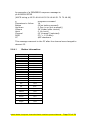
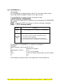
Professional Mobile Radios
Computer controlled
Radio-interface
(CCRI)
Protocol Manual
version 01-03
Mobile Radio Computer-Controlled Radio interface protocol Manual
Page 1 of 24
Contents
Preface:........................................................................................... 3
Scope of Manual.......................................................................... 3
Publication Record ....................................................................... 3
Associated Propriety Documentation: ............................................. 3
Supported Portable Radios: .......................................................... 3
Alert Notices:.............................................................................. 4
Contact details: .......................................................................... 4
Copyright: .................................................................................. 4
Abbreviations: ............................................................................ 5
Introduction: .................................................................................... 6
1.1 Compability ......................................................................... 6
1.2 Serial ports ......................................................................... 7
1.3 Auxiliary connector ............................................................... 7
1.4 Before Operating.................................................................. 8
1.5 Limitations .......................................................................... 8
Command Modes .............................................................................. 9
2.1 Entering Command Mode ...................................................... 9
2.2 CCDI Command Format ........................................................ 9
2.3 Restrictions ....................................................................... 10
2.4 Calculating the CCDI [CHECKSUM] ....................................... 10
2.4.1
Checksum Example ....................................................... 10
2.5 Commands to the Radio ...................................................... 11
2.5.1
FUNCTION ................................................................... 12
2.5.1.1
Examples of FUNCTION commands ............................... 14
2.5.2
GO_TO_CHANNEL ......................................................... 15
2.6
Messages from the Radio ............................................... 16
2.6.1
ACKNOWLEDGE ............................................................ 16
2.6.2
NOT ACKNOWLEDGE ..................................................... 17
2.6.3
ERROR......................................................................... 17
2.6.4
PROGRESS „p‟ ............................................................... 19
2.6.4.1
Button information: ................................................... 20
2.6.5
PROGRESS „q‟ ............................................................... 21
2.6.6
RADIO_SERIAL ............................................................. 22
Rotronix Ltd General Software License Agreement .............................. 23
Mobile Radio Computer-Controlled Radio interface protocol Manual
Page 2 of 24
Preface:
Scope of Manual
This manual contains reference information about the CCRI protocol
for the Motorola Professional Mobile Radios CCRI option board. It
applies to CCRI version 1.01 and radio software version R03.10.03
and later versions.
Publication Record
Issue
Publication Date
Author
Description
1.01
December 2007
Hans de Roode
First issue
1.02
January 2008
HDR
Corrected start-up description on page 16 and 21
1.02/1
January 2008
HDR
Added „alert‟ f41-- command on page 14
1.02/2
August 2008
HDR
Corrected Auxiliary connector pin 1 indication
Associated Propriety Documentation:
Motorola service manual
Motorola PROIS 2.03 Manual
Motorola PROIS 2.03 Electrical Manual: (Part No: 1202899J28)
Supported Portable Radios:
GM340, GM360, GM380, GM339, GM399, PRO3100, CDM750,
GM140,PRO5100, CDM1250, PRO7100, CDM1550, GM160,
GM338, GM398, CDM1550LS+,GM338LS.
Mobile Radio Computer-Controlled Radio interface protocol Manual
Page 3 of 24
Alert Notices:
Within this manual, four types of alerts are given to the reader:
warning,
caution, important and note. The following paragraphs illustrate each
type
of alert and its associated symbol.
Warning!!
This alert is used when there is a potential risk of death or serious
injury.
Caution
This alert is used when there is the risk of minor or moderate injury to
people.
Important
This alert is used to warn about the risk of equipment damage or
malfunction.
Note
This alert is used to highlight information that is required to ensure
that procedures are performed correctly.
Contact details:
Rotronix Ltd
135 Darnley Road
RD3 Amberley, New Zealand
Commercial e-mail:
[email protected]
Technical e-mail:
[email protected]
Copyright:
Copyright protects original works, regardless of whether the
work is published or unpublished. Under the Copyright Act
1994, copyright automatically applies as soon as the work is
put into material form – whether in print, stored on computer
or recorded in some way. As a signatory to the Berne
convention, New Zealand protects the rights of copyright
owners from other countries in the same way it does for our
own copyright owners. It is unlawful to copy all or part of this
manual without a license or without approval from the
copyright owner, unless there is a statutory exception to such
infringement.
Mobile Radio Computer-Controlled Radio interface protocol Manual
Page 4 of 24
Abbreviations:
Abbreviation
Description
3DK
ASCII
Third-Party Developer‟s Kit
American Standard Code for Information Interchange
AVL
Automatic Vehicle Location
CCRI
Computer Controlled Radio Interface
CRC
Cyclic Redundancy Check
CTCSS
Continuous Tone Coded Squelch System
CTS
Clear to Send
DCE
Data Circuit-Terminating Equipment
DCS
Data Carrier System
DTE
Data Terminal Equipment
DTMF
Dual Tone Multi-Frequency
FEC
Forward Error Correction
FFSK
Fast Frequency Shift Keying
GPIO
General Purpose Input/Output
IPN
Internal Part Number
LED
Light-Emitting Diode
MSD
Most Significant Digit
National Marine Electronics Association standard.
Combined electrical and data specification for
communication between marine electronics and GPS
receivers.
Personal
Computer
NMEA
PC
PTT
RTS
Press To Talk
Motorola proprietary Professional Radio Option
Interface Specification
Recommended Minimum sentence C. NMEA GPS
message type for the minimum recommended
transmit/GPS
data.
Request to Send
Rx
Receive
RXD
Receive Data
SDM
Short Data Message
PROIS
RMC
TX
Transmit
TXD
Transmit Data
UART
Universal Asynchronous Receiver-Transmitter
XON
Transmitter On
XOFF
Transmitter Off
Mobile Radio Computer-Controlled Radio interface protocol Manual
Page 5 of 24
Introduction:
The Computer Controlled Radio Interface (CCRI) protocol is a
Rotronix Ltd proprietary command protocol embedded in the PROIS
option board for the Motorola Professional Mobile Radios and GM399
radios, and used for communicating with the radio via an
asynchronous serial port.
The radio is the DCE and is connected directly to the DTE, usually a
PC, via the serial port.
PC running
Com
Application
GM399
One mode of operation is available:
Command mode
When in Command mode, commands and response messages are
passed between the PC and the radio using the CCRI protocol. CCRI
commands can also be used to obtain GPS data and NMEA messages
from the radio (Note: Not yet implemented). When in Command
mode, communication between the PC and the radio
is set to 19200 baud.
1.1
Compability
This manual supports CCRI version 1.xx and later.
The radio programming software used should be the latest released
version for the Motorola Professional Mobile Radios. Refer to the
Motorola authorized dealer for the latest version.
Mobile Radio Computer-Controlled Radio interface protocol Manual
Page 6 of 24
1.2
Serial ports
There is one port available for CCRI asynchronous serial
communication with the Motorola Professional Mobile Radio (inverted
3.3V logic). The microphone and accessory port are used for the
programming of the radio. The internal options connector is used for
connecting to the option board.
1.3
Auxiliary connector
The auxiliary connector is the interface for optional external devices
that are typically connected to a radio. The auxiliary connector is a 7way flat-socket. The auxiliary connector provides a serial port, and
audio I/O.
Note The space for a mating plug is limited to 18.6 mm width and
2.6 mm in height. It is recommended that you test the plug to be
used before manufacturing a cable.
If the auxiliary cable is longer than 1 meter, it is recommended that
the cable is shielded. The diagram shows the recommended shielding
arrangement. The earth braid wire (bare copper) should only be
earthed at the radio end of the cable.
Auxiliary
Connector
Pin 1
Accessory
connector
Mobile Radio Computer-Controlled Radio interface protocol Manual
Page 7 of 24
Pinout
1
2
3
4
Pin
Description
Signal type
1
Digital ground
Digital 0V
2
Radio speaker audio in
(Public address)
Analogue 0.3 Vpp.
3
RX audio out.
Analogue 0.2 Vpp.
4
TX audio in.
Analogue 0.2Vpp.
5
6
5
7
6
rear view
7
1.4
Asynchronous serial
port Transmit data
Asynchronous serial
port Receive data
Digital. 3V3 CMOS.
Digital. 3V3 CMOS.
Analogue ground
Analogue 0V.
Before Operating
Before using CCDI, the following is useful to check.
The radio must be correctly programmed for use with the PROIS
protocol .
The serial port of the radio is connected to a serial source like an
embedded application or a desk-top computer via a suitable levelshifter, e.g. 3.3V to RS232 levels.
1.5
Limitations
Important Some data applications require extended
transmission times. This may be for larger file transfers or for realtime telemetry information. This may put undue stress on the radio
transmitter and care must be taken to control transmission times.
Mobile Radio Computer-Controlled Radio interface protocol Manual
Page 8 of 24
Command Modes
Command mode uses the T.L. Parker Ltd proprietary Computer
Controlled Radio Interface (CCRI), a command protocol embedded in
the PROIS option- board firmware, it is accessed using the serial port
lines from the PC. In this mode, the baud rate between the computer
equipment (DTE) and the radio (DCE) is 19200 baud.
In Command mode, the PC sends command sequences to the radio
and waits for a prompt before beginning the next transaction. Some
commands require the radio to send a CCRI message in response.
Messages sent to the radio will always be responded to by the
prompt.
Unsolicited messages such as PROGRESS or ERROR messages are
sent by the radio if there is a significant change in its state that the
PC should be aware of. If an error is detected, an unsolicited ERROR
message is sent by the radio to the PC. The radio cannot send
messages that require a reply.
2.1 Entering Command Mode
The radio will change to Command mode on receipt of the “hartbeat” command (f010 Check-Sum) and stays in command mode until
2 seconds have elapsed after the last “hart-beat” has been received.
When in command mode the PC has full control of the radio, display
and indicators e.g. in the case of a button press, the radio will only
report the event to the PC.
2.2 CCDI Command Format
All CCRI message packets take the general form:
[IDENT] [SIZE] [PARAMETERS] [CHECKSUM] <CR>
[IDENT] = The message identifier. Identifiers are single ASCII
characters (lower-case alphabetical) which categorizes the message
type.
[SIZE] = The number of characters which make up the
[PARAMETERS] field. [SIZE] is an 8-bit number expressed in
ASCII hex notation (two characters).
[PARAMETERS] = An optional field, depending upon the command.
Parameter values are generally character strings unless explicitly
stated otherwise. Parameter type is dependent upon the command,
and often has multiple parts.
[CHECKSUM] = An 8-bit checksum of the [IDENT], [SIZE] and
[PARAMETERS] fields. Expressed in two character ASCII hex
notation.
<CR> = The carriage return (0Dh) packet terminator.
Mobile Radio Computer-Controlled Radio interface protocol Manual
Page 9 of 24
2.3 Restrictions
All characters in a message are printable ASCII.
Where numeric values are represented in ASCII hex notation
(two characters per byte), characters A to F are upper case.
The minimum length of a command packet is 5 characters. For
example q002F is the QUERY command where [SIZE] = 00 as there
is no [PARAMETERS] field required.
The maximum length of the [PARAMETERS] field is 40 characters.
The maximum length of the command packet is therefore 45
characters.
2.4 Calculating the CCDI [CHECKSUM]
[CHECKSUM] is calculated by applying the following algorithm:
1.
2.
4.
Take the sum, modulo-256 of all message bytes preceding the
[CHECKSUM].
Form the two‟s complement of the sum.
Convert the binary number into two ASCII hex digits, MSD first.
2.4.1 Checksum Example
s0D050800TESTHi!DA
1.
Take the modulo-2 sum of all message bytes preceding
[CHECKSUM].
73h, 0 = 30h, D = 44h etc. therefore the sum is:
73 + 30 + 44 + 30 + 35 + 30 + 38 + 30 + 30 + 54 + 45 + 53 +
54 + 48 + 69 + 21 = 426h
2.
426h mod 256 = 26h
3.
Form the two‟s complement is 0 - 26h = DAh
4.
Convert the binary number into two ASCII hex digits, 44h 41h.
Mobile Radio Computer-Controlled Radio interface protocol Manual
Page 10 of 24
2.5 Commands to the Radio
The following commands are available to send from the PC to control
the radio.
Command
Command
Function
FUNCTION
f
controls various hardware, miscellaneous radio
functions and heart-beat
GO_TO_CHANNEL
g
sets the radio to a particular channel
When a command is received without error by the option board and
all parameters are valid, the command is forwarded to the radio, and
an “Acknowledge” command is returned to the PC to signify that
another may begin. If an error arises, the PC is notified with an
appropriate “Not acknowledge” response or in the case of a
parameter error, an Error-response message is send.
Mobile Radio Computer-Controlled Radio interface protocol Manual
Page 11 of 24
2.5.1 FUNCTION
The FUNCTION command provides access to various hardware and
miscellaneous functions. It has the following format:
f [SIZE] [FUNCTION] [SUBFUNCTION] [QUALIFIER] [CHECKSUM]
„f ‟ is sent as a single ASCII character and represents the FUNCTION
command.
[SIZE] two ASCII characters indicating the number of bytes
In the PARAMETER fields.
[FUNCTION] is a single ASCII characters representing the required
function category.
[SUBFUNCTION] is up to two ASCII characters and is used to
extend the range of the [FUNCTION] parameter.
[QUALIFIER] is an ASCII character string representing the action
to be taken, depending on the value of [FUNCTION] and
[SUBFUNCTION].
[FUNCTION] [SUBFUNCTION] [QUALIFIER]
Action
0
none
Switch to CCR mode, needs to be
send with intervals < 2 Sec.
0
Disable RX audio (Mute radio).
1
Enable RX audio (Unmute radio).
2
0-25
Enable volume and set level. 0 =
low, 25= max loudness.
3
26
Return volume control to the radio
0
Disable Public Address Mode.
1
Enable Public Address Mode.
(Enable audio input to the radio Audio
Amplifier)
10, 0
Red LED OFF
11, 0
Red LED ON steady
11, 1
Red LED ON steady, slow on/off
11, 2
Red LED ON steady, fast on/off
20, 0
Green LED OFF
21, 0
Green LED ON steady
1
0 (functions)
4
6
Mobile Radio Computer-Controlled Radio interface protocol Manual
Page 12 of 24
6
0 (functions)
7
8
21, 1
Green LED, slow on/off
21, 2
Green LED, fast on/off
30, 0
Yellow LED OFF
31, 1
Yellow LED ON, steady
31, 2
Yellow LED, slow on/off
31, 3
Yellow LED, fast on/off
40, 0
Backlights OFF
41, 1
Backlights LED ON, steady
41, 2
Backlights, slow on/off
41, 3
Backlights, fast on/off
20
Speaker Icon off
21
Speaker Icon on
30
phone Icon off
31
phone Icon on
40
alarm Icon off
41
alarm Icon on
50
tone Icon off
51
tone Icon on
60
scanning Icon off
61
scanning Icon on
70
scan stopped Icon off
71
scan stopped Icon on
0
Microphone on, flat-audio input
off.
Microphone off, flat-audio input
on.
Transmitter off
1
Transmitter on
0
1
9
1
4
(user control)
3
alert type:
0 0: 300 Hz 75 mS
0 1: 910 Hz 75 mS
0 2: 300 Hz 375mS
0 3: 910 Hz 375 mS
volume 0 -25 (0 = min, 25 = max)
26 = radio volume
1, max 14 ASCII char.
Display text line 1
2, max 14 ASCII char.
Display line text 2
3, max 14 ASCII char.
Display text line 3
Mobile Radio Computer-Controlled Radio interface protocol Manual
Page 13 of 24
2.5.1.1
Examples of FUNCTION commands are:
f0200D8
Enable Computer Control Radio Mode.
Also used as “heart-beat”, time-out is 2 seconds.
f17 43 1 12345678901234 CS
Send text “12345678901234” to dislay line 1.
f06 41 01 10 CS
Sound alert tone 1 in radio speaker, with volume level
10
The tone is self-terminating
f04 0101CS
Mute speaker audio
f04 0100CS
Unmute speaker audio
Mobile Radio Computer-Controlled Radio interface protocol Manual
Page 14 of 24
2.5.2 GO_TO_CHANNEL
The GO_TO_CHANNEL command tells the radio to change to another
conventional mode (channel) that is part of the radio code-plug. The
specified channel can be assigned to a scan/vote group, or the
GO_TO_CHANNEL command can load a “soft-channel” in the radio,
specifying TX frequency, RX frequency. RX CTCSS frequency, TX CTCSS
frequency and channel-width (12.5, 20 or 25 kHz).
The GO_TO_CHANNEL command has the following format:
g [SIZE] [ZONE] [CHANNEL_NO] [CHECKSUM]
„g‟ is sent as a single ASCII character and represents the
GO_TO_CHANNEL command.
[ZONE] is a two-character string representing the new zone
ZONE = 02:
CHANNEL_NO is sent as two ASCII character and represents the
channel number.
Example:
Hard-channel change to channel 1: g04020172
Note
If the radio is switched to a channel with scan/vote enabled, it
will adhere to the scan/vote conditions of that channel.
ZONE = 08:
Soft-channel change.
CHANNEL_NO = (txFrequency/125) (rxFrequency/125)
(txCTCSS*10) (rxCTCSS*10) 0 0
Example: g 32 08 120610 11F350 04CE 04CE 38 00000000 9F
Note: frequencies are in Hertz.
TX = 147.650 , RX = 147.050, TX CTCSS = 123 Hz,
RX CTCSS = 123 Hz, low power, 12.5 kHz channel spacing.
The source-code of a software application is available from T.L.
Parker Ltd Technical Support which will give examples of the use of
the commands and calculate the checksum for any given command
and parameters.
Please contact Technical Support (refer to “T.L. Parker Contact
Information” on page 2).
Mobile Radio Computer-Controlled Radio interface protocol Manual
Page 15 of 24
2.6 Messages from the Radio
At switch-on of the radio, the radio sends the following message to
the PC: "Motorola GM399 date [DATE], build [BUILD]",
Were “DATE” denotes the compile-date of the option-board and
“BUILD” denotes the compile number of the option-board software
The following messages are sent from the radio to the PC. Some are
solicited by commands from the PC, while others are unsolicited and
are sent because of changes within the radio-status.
Command
Character
Function
ACKNOWLEDGE
+
Acknowledgement of a command
NOT ACKNOWLEDGE
-
Communication error in received
command
ERROR
e
Transaction processing error
PROGRESS
p
Radio state progress report 1
PROGRESS
q
Radio state progress report 2
RADIO_SERIAL
n
Radio serial number
2.6.1 ACKNOWLEDGE
Solicited.
The ACKNOWLEDGE message advises the PC that the radio has
received the command successfully.
The ERROR message has the following format:
+[SIZE] [COMMAND] [CHECKSUM]
[COMMAND] is a single character representing the command
sent to the radio.
Mobile Radio Computer-Controlled Radio interface protocol Manual
Page 16 of 24
2.6.2 NOT ACKNOWLEDGE
Solicited.
The “NOT ACKNOWLEDGE” message advises the PC that the option
board has detected an error in the received command, this can be
any of the following errors.
FRAMING_ERROR
ETYPE = 26
PARITY_ERROR
ETYPE = 14
DATA_OVERRUN
ETYPE = 18
[SIZE] is more than 40 characters ETYPE = 03
RX Buffer is full
ETYPE = 07
Checksum error
ETYPE = 04
Serial communication port time-out ETYPE = 05
The “NOT ACKNOWLEDGE” message has the following format:
-[SIZE] [ETYPE] [COMMAND] [CHECKSUM]
[ETYPE] is a dual digit character representing the error detected.
[COMMAND] is a single character representing the command sent
to the radio.
The FRAMING_ERROR flag can be used for detecting out-of-sync
conditions, detecting break conditions and protocol handling.
The DATA_OVERRUN Flag indicates data loss due to a UART-Receiver
buffer full condition it occurs when the receive buffer is full (two
characters),
The PARITY_ERROR Flag indicates that the next frame in the receive
buffer had a parity error when received. If parity check is not enabled
the PARITY_ERROR Flag will always be read zero.
2.6.3 ERROR
Solicited and unsolicited.
The ERROR message advises the PC that the radio has detected an
error condition and cannot proceed with the current transaction. In
some cases an exception condition in the radio may cause an ERROR
message to be sent to the PC independently of any control
transactions. This is a system error, which is an unsolicited message.
The ERROR message has the following format:
e [SIZE] [ETYPE] [ERRNUM] [CHECKSUM]
„e‟ is sent as a single ASCII character and represents the ERROR
command.
[ETYPE] is a single character representing the error category.
Mobile Radio Computer-Controlled Radio interface protocol Manual
Page 17 of 24
[ERRNUM] is two ASCII hex characters which identify the specific
error condition.
[ETYPE]
[ERRNUM]
Error description
T
3
checksum error PROIS
S
1
radio initiated power-down
S
0
radio switched successfully to CCR mode
O
Xh
Unsupported command X in hex notation
G
1
unsupported “Go to Channel” command
F
1
unsupported “Functions” command
F
6
unsupported “Functions 0” command
F
7
unsupported “Functions 4” command
R
1
PROIS start-up error
R
2
PROIS Data/Ready request not responding
R
5
PROIS buffer not emptied within the set time
R
15
PROIS buffer overflow
R
33
CCR timer (2 sec) expired radio has returned to normal operation
[ETYPE] „R‟ indicates a restart of the radio, this means that after
the restart the radio is in default CCRI state, i.e. the same as after a
“power-up” and switch to CCDI state.
[ETYPE] e07S0081, this is not an error-condition, but an indication
that the radio switched successfully to CCR mode.
Mobile Radio Computer-Controlled Radio interface protocol Manual
Page 18 of 24
2.6.4 PROGRESS ‘p’
Unsolicited.
The PROGRESS message advises the PC of the radio status when
some significant change of state in the radio occurs.
When the radio is receiving a signal, this message is sent every ½
second to update the RSSI signal.
The PROGRESS message has the following format:
p [SIZE][PARA] [CHECKSUM]
„p‟ is sent as a single ASCII character and represents the PROGRESS
command.
SIZE number of ASCII characters to follow including checksum
PARA = [button, upDown, volume, hook, channel, RSSI].
[PARA]
Function
Button
XX
A button on the control-head of the radio has been
pressed
upDown
X
Key pressed or released
“1” If a key is pressed, “0” otherwise
Volume
XX
Volume
Volume control, range is from 0 (min) to 25 (max),
26 indicates that radio is in control of the volume
Hook
X
Hook
“1” If a microphone is of the hook, “0” otherwise
Channel
XX
Channel
The channel the radio is working on.
Range 01- 255, “00” indicates that the radio is in
“soft-channel” mode
RSSI
XX
RSSI
Receive signal strength from 0 (> -50dBm) to 255
(< -123dBm)
Mobile Radio Computer-Controlled Radio interface protocol Manual
Page 19 of 24
An example of a PROGRESS response message is:
p1400026003FF0E
(ASCII string p 49 52 48 48 48 50 54 48 48 51 70 70 48 69)
p
Characters to follow
Button
Up/down
Volume
Hook
Channel
RSSI
CC
progress command
14
00(no button pressed)
0 (key is up (not pressed))
26 (under radio control)
0 (on hook)
03 (channel 3 selected)
FF (< -123 dBm)
$0E checksum
This message was sent to the PC after the channel was changed to
channel 03.
2.6.4.1
Button information:
Button
Pressed
1
2
3
4
5
6
7
8
9
0
*
#
P1
Button Press
Value
$01
$02
$03
$04
$05
$06
$07
$08
$09
$0A
$0B
$0C
$11
P2
$12
P3
$13
P4
$1A
Exit
$14
Select
$15
Up
$16
Down
$17
Left
$18
Right
$19
Mobile Radio Computer-Controlled Radio interface protocol Manual
Page 20 of 24
2.6.5 PROGRESS ‘q’
Unsolicited.
The PROGRESS message advises the PC of the radio status when
some significant change of state in the radio occurs.
The PROGRESS message has the following format:
q [SIZE][PARA] [CHECKSUM]
„q‟ is sent as a single ASCII character and represents the PROGRESS
command.
SIZE number of ASCII characters to follow including checksum
PARA = [PTT, Receive-mute].
[PARA]
Function
PTT
X
“1” If microphone PTT is pressed, “0” otherwise.
“0”, no receive, mute closed, transmitter down
Receiver
“1”, receiving, mute opened
mute
“3”, receiving with valid CTCSS, mute opened
X
“4”, CTS clear to send , transmitter up and ready
An example of a PROGRESS „q‟ response message is:
q0604C5
(ASCII string: q 48 54 48 52 67 53)
q
Progress command
Characters to follow
14
PTT
0 (PTT not pressed)
Mute
4 Clear to send, (transmitter up and ready)
CC
$C5
This message was sent after the transmitter was switched on.
Mobile Radio Computer-Controlled Radio interface protocol Manual
Page 21 of 24
2.6.6 RADIO_SERIAL
Unsolicited.
The RADIO_SERIAL message is sent to the PC when the radio is
switched to Computer Control Radio Mode (command f0200D8)
The RADIO_SERIAL message has the following format:
n [SIZE] [SERIAL_NUMBER] [CHECKSUM]
„n‟ is sent as a single ASCII character and represents the
RADIO_SERIAL command.
SIZE number of ASCII characters to follow including checksum
SERIAL_NUMBER is a string identifying the serial number in the
radio.
CHECKSUM two complement of the whole message
An example of the RADIO_SERIAL response message is:
n02103TEQL293EE
(ASCII string: n 48 50 49 48 51 84 69 81 76 50 57 51 69 69)
This message indicates that the Radio has serial number:
103TEQL293
Mobile Radio Computer-Controlled Radio interface protocol Manual
Page 22 of 24
Rotronix Ltd General Software License
Agreement
This legal document is an Agreement between you (the “Licensee”) and Rotronix Ltd. By using any of the
Software or Firmware items prior-installed in the related ROTRONIX LTD product, included on CD or
downloaded from the ROTRONIX LTD website, (hereinafter referred to as “the Software or Firmware”) you
agree to be bound by the terms of this Agreement. If you do not agree to the terms of this Agreement, do not
install and use any of the Software or Firmware. If you install and use any of the Software or Firmware that will
be deemed to be acceptance of the terms of this license agreement. The terms of this Agreement shall apply
subject only to any express written terms of agreement to the contrary between ROTRONIX LTD and the
licensee.
License
ROTRONIX LTD GRANTS TO YOU AS LICENSEE THE NON- EXCLUSIVE RIGHT TO USE THE SOFTWARE OR
FIRMWARE ON A SINGLE MACHINE PROVIDED YOU MAY ONLY:
1. COPY THE SOFTWARE OR FIRMWARE INTO ANY MACHINE READABLE OR PRINTED FORM FOR BACKUP
PURPOSES IN SUPPORT OF YOUR USE OF THE PROGRAM ON THE SINGLE MACHINE (CERTAIN PROGRAMS,
HOWEVER, MAY INCLUDE MECHANISMS TO LIMIT OR INHIBIT COPYING, THEY ARE MARKED “COPY
PROTECTED”),PROVIDED THE COPYRIGHT NOTICE MUST BE REPRODUCED AND INCLUDED ON ANY SUCH
COPY OF THE SOFTWARE OR FIRMWARE;
AND / OR
2. MERGE IT INTO ANOTHER PROGRAM FOR YOUR USE ON THE SINGLE MACHINE (ANY PORTION OF ANY
SOFTWARE OR FIRMWARE MERGED INTO ANOTHER PROGRAM WILL CONTINUE TO BE SUBJECT TO THE TERMS
AND CONDITIONS OF THIS AGREEMENT). THE LICENSEE MAY NOT DUPLICATE, MODIFY, REVERSE COMPILE
OR REVERSE ASSEMBLE ANY SOFTWARE OR FIRMWARE IN WHOLE OR PART.
Important Notice
THE SOFTWARE OR FIRMWARE MAY CONTAIN OPEN SOURCE SOFTWARE COMPONENTS (“OPEN SOURCE
COMPONENTS”). OPEN SOURCE COMPONENTS ARE EXCLUDED FROM THE TERMS OF THIS AGREEMENT EXCEPT
AS EXPRESSLY STATED IN THIS AGREEMENT AND ARE COVERED BY THE TERMS OF THEIR RESPECTIVE
LICENCES WHICH MAY EXCLUDE OR LIMIT ANY WARRANTY FROM OR LIABILITY OF THE DEVELOPERS AND/OR
COPYRIGHT HOLDERS OF THE OPEN SOURCE COMPONENT FOR THE PERFORMANCE OF THOSE OPEN SOURCE
COMPONENTS. YOU AGREE TO BE BOUND BY
THE TERMS AND CONDITIONS OF EACH SUCH LICENCE. FOR MORE INFORMATION SEE:
http://www.opensource.org/licenses
Title to Software
THIS AGREEMENT DOES NOT CONSTITUTE A CONTRACT OF SALE IN RELATION TO THE SOFTWARE OR
FIRMWARE SUPPLIED TO THE LICENSEE. NOT WITHSTANDING THE LICENSEE MAY OWN THE MAGNETIC OR
OTHER PHYSICAL MEDIA ON WHICH THE SOFTWARE OR FIRMWARE WAS ORIGINALLY SUPPLIED, OR HAS
SUBSEQUENTLY BEEN RECORDED OR FIXED, IT IS A FUNDAMENTAL TERM OF THIS AGREEMENT THAT AT ALL
TIMES TITLE AND OWNERSHIP OF THE SOFTWARE OR FIRMWARE, WHETHER ON THE ORIGINAL MEDIA OR
OTHERWISE, SHALL REMAIN VESTED IN ROTRONIX LTD OR THIRD PARTIES WHO HAVE GRANTED LICENCES
TO ROTRONIX LTD.
Term and Termination
THIS LICENCE SHALL BE EFFECTIVE UNTIL TERMINATED IN ACCORDANCE WITH THE PROVISIONS OF THIS
AGREEMENT. THE LICENSEE MAY TERMINATE THIS LICENCE AT ANY TIME BY DESTROYING ALL COPIES OF
THE SOFTWARE OR FIRMWARE AND ASSOCIATED WRITTEN MATERIALS. THIS LICENCE WILL BE TERMINATED
AUTOMATICALLY AND WITHOUT NOTICE FROM ROTRONIX LTD IN THE EVENT THAT THE LICENSEE FAILS TO
COMPLY WITH ANY TERM OR CONDITION OF THIS AGREEMENT. THE LICENSEE AGREES TO DESTROY ALL
COPIES OF THE SOFTWARE OR FIRMWARE AND ASSOCIATED WRITTEN MATERIALS IN THE EVENT OF SUCH
TERMINATION.
Mobile Radio Computer-Controlled Radio interface protocol Manual
Page 23 of 24
Limited Warranty
THE SOFTWARE OR FIRMWARE (INCLUDING OPEN SOURCE COMPONENTS) IS SUPPLIED BY ROTRONIX LTD
AND ACCEPTED BY THE LICENSEE “AS IS” WITHOUT WARRANTY OF ANY KIND EITHER EXPRESSED OR
IMPLIED, INCLUDING BUT NOT BEING LIMITED TO ANY IMPLIED WARRANTIES AS TO MERCHANTABILITY OR
FITNESS FOR ANY PARTICULAR PURPOSE. THE LICENSEE ACKNOWLEDGES THAT THE SOFTWARE OR
FIRMWARE (INCLUDING OPEN SOURCE COMPONENTS) IS USED BY IT IN BUSINESS AND ACCORDINGLY TO
THE MAXIMUM EXTENT PERMITTED BY LAW NO TERMS OR WARRANTIES WHICH ARE IMPLIED BY LEGISLATION
SHALL APPLY TO THIS AGREEMENT. ROTRONIX LTD DOES NOT WARRANT THAT THE FUNCTIONS CONTAINED
IN THE SOFTWARE OR FIRMWARE (INCLUDING OPEN SOURCE COMPONENTS) WILL MEET THE LICENSEE‟S
REQUIREMENTS OR THAT THE OPERATION OF THE SOFTWARE OR FIRMWARE (INCLUDING OPEN SOURCE
COMPONENTS) WILL BE UNINTERRUPTED OR ERROR FREE.
Exclusion of Liability
IN NO CIRCUMSTANCES SHALL ROTRONIX LTD BE UNDER ANY LIABILITY TO THE LICENSEE, OR ANY OTHER
PERSON WHATSOEVER, WHETHER IN TORT (INCLUDING NEGLIGENCE), CONTRACT (EXCEPT AS EXPRESSLY
PROVIDED IN THIS AGREEMENT), EQUITY, UNDER ANY STATUTE, OR OTHERWISE AT LAW FOR ANY LOSSES
OR DAMAGES WHETHER GENERAL, SPECIAL, EXEMPLARY, PUNITIVE, DIRECT, INDIRECT OR CONSEQUENTIAL
ARISING OUT OF OR IN CONNECTION WITH ANY USE OR INABILITY OF USING THE SOFTWARE OR FIRMWARE
(INCLUDING OPEN SOURCE COMPONENTS). THE LICENSEE‟S SOLE REMEDY AGAINST ROTRONIX LTD WILL BE
LIMITED TO BREACH OF CONTRACT AND ROTRONIX LTD‟S SOLE AND TOTAL LIABILITY FOR ANY SUCH CLAIM
SHALL BE LIMITED AT THE OPTION OF ROTRONIX LTD TO THE REPAIR OR REPLACEMENT OF THE SOFTWARE
OR FIRMWARE OR THE REFUND OF THE PURCHASE PRICE OF THE SOFTWARE OR FIRMWARE.
General
THE LICENSEE CONFIRMS THAT IT SHALL COMPLY WITH THE PROVISIONS OF LAW IN RELATION TO THE
SOFTWARE OR FIRMWARE.
Law and Jurisdiction
THIS AGREEMENT SHALL BE SUBJECT TO AND CONSTRUED IN ACCORDANCE WITH NEW ZEALAND LAW AND
DISPUTES BETWEEN THE PARTIES CONCERNING THE PROVISIONS HEREOF SHALL BE DETERMINED BY THE
NEWZEALAND COURTS OF LAW. PROVIDED HOWEVER ROTRONIX LTD MAY AT ITS ELECTION BRING
PROCEEDINGS FOR BREACH OF THE TERMS HEREOF OR FOR THE ENFORCEMENT OF ANY JUDGEMENT IN
RELATION TO A BREACH OF THE TER MS HEREOF IN ANY JURISDICTION ROTRONIX LTD CONSIDERS FIT FOR
THE PURPOSE OF ENSURING COMPLIANCE WITH THE TERMS HEREOF OR OBTAINING RELIEF FOR BREACH OF
THE TERMS HEREOF.
No Dealings
THE LICENSEE MAY NOT SUBLICENSE, ASSIGN OR TRANSFER THE LICENCE OR THE PROGRAM EXCEPT AS
EXPRESSLY PROVIDED IN THIS AGREEMENT. ANY ATTEMPT OTHERWISE TO SUBLICENSE, ASSIGN OR
TRANSFER ANY OF THE RIGHTS, DUTIES OR OBLIGATIONS HEREUNDER IS VOID.
No Other Terms
THE LICENSEE ACKNOWLEDGES THAT IT HAS READ THIS AGREEMENT, UNDERSTANDS IT AND AGREES TO BE
BOUND BY ITS TERMS AND CONDITIONS. THE LICENSEE FURTHER AGREES THAT SUBJECT ONLY TO ANY
EXPRESS WRITTEN TERMS OF AGREEMENT TO THE CONTRARY BETWEEN ROTRONIX LTD AND THE LICENSEE
THIS IS THE COMPLETE AND EXCLUSIVE STATEMENT OF THE AGREEMENT BETWEEN IT AND ROTRONIX LTD IN
RELATION TO THE SOFTWARE OR FIRMWARE WHICH SUPERSEDES ANY PROPOSAL OR PRIOR AGREEMENT,
ORAL OR WRITTEN AND ANY OTHER COMMUNICATIONS BETWEEN THE LICENSEE AND ROTRONIX LTD
RELATING TO THE SOFTWARE OR FIRMWARE
Mobile Radio Computer-Controlled Radio interface protocol Manual
Page 24 of 24