1
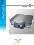
PS
Shipping Scales
Operator / Technical
Manual
with GeoCal™ and USB
64067860
08/09
©METTLER TOLEDO. 2009
No part of this manual may be reproduced or transmitted in any form or by any means,
electronic or mechanical, including photocopying and recording, for any purpose without the
express written permission of METTLER TOLEDO.
U.S. Government Restricted Rights: This documentation is furnished with Restricted Rights.
METTLER TOLEDO
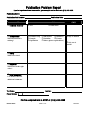
Publication Problem Report
If you find a problem with our documentation, please complete and fax this form to (614) 438-4355
Publication Name:
Publication Part Number:
Publication Date:
PROBLEM(S) TYPE:
DESCRIBE PROBLEM(S):
Technical Accuracy
Text
Completeness
Procedure/step
Example
Explanation
What information is
missing?
INTERNAL USE
ONLY
Illustration
Illustration
Definition
Guideline
Feature
Other (please explain below)
Info. in manual
Info. not in
manual
Clarity
What is not clear?
Sequence
What is not in the right
order?
Other Comments
Use another sheet for
additional comments.
Your Name:
Phone Number: (
Location:
)
Fax this completed form to MTWT at (614) 438-4355
METTLER TOLEDO
Printed in U.S.A.
64067860
INTRODUCTION
This publication is provided as a guide for individuals in the operation, use, and care of this
METTLER TOLEDO product.
Further information or assistance regarding this product may be obtained by writing to:
METTLER TOLEDO
1900 Polaris Parkway
Columbus, OH 43240-2020
(614) 438-4400
WARNING!
This equipment generates, uses, and can radiate radio frequency energy and if not installed and
used properly, i.e., in accordance with the instructions manual, may cause harmful interference
to radio communications. It has been tested and found to comply with the limits for a Class A
computing device pursuant to Subpart J of Part 15 of FCC Rules, which are designed to provide
reasonable protection against such interference when operated in a commercial environment.
Operation of this equipment in a residential area may cause interference, in which case the user
at his own expense will be required to take whatever measures may be required to correct the
interference.
METTLER TOLEDO RESERVES THE RIGHT TO MAKE REFINEMENTS OR
CHANGES WITHOUT NOTICE.
METTLER TOLEDO RESERVES THE RIGHT TO MAKE REFINEMENTS OR
CHANGES WITHOUT NOTICE.
PRECAUTIONS
READ this manual BEFORE
operating or servicing this
equipment.
FOLLOW these instructions
carefully.
SAVE this manual for future
reference.
WARNING
DISCONNECT ALL POWER TO THIS UNIT BEFORE
INSTALLING, SERVICING, CLEANING, OR REMOVING THE
FUSE. FAILURE TO DO SO COULD RESULT IN BODILY
HARM AND/OR PROPERTY DAMAGE.
CAUTION
OBSERVE PRECAUTIONS FOR HANDLING
ELECTROSTATIC SENSITIVE DEVICES.
DO NOT allow untrained
personnel to operate, clean,
inspect, maintain, service, or
tamper with this equipment.
ALWAYS DISCONNECT this
equipment from the power
source before cleaning or
performing maintenance.
CALL METTLER TOLEDO for
parts, information, and
service.
WARNING
ONLY PERMIT QUALIFIED PERSONNEL TO SERVICE THIS
EQUIPMENT. EXERCISE CARE WHEN MAKING CHECKS,
TESTS AND ADJUSTMENTS THAT MUST BE MADE WITH
POWER ON. FAILING TO OBSERVE THESE PRECAUTIONS
CAN RESULT IN BODILY HARM.
WARNING
FOR CONTINUED PROTECTION AGAINST SHOCK
HAZARD, CONNECT TO PROPERLY GROUNDED OUTLET
ONLY. DO NOT REMOVE THE GROUND PRONG.
CAUTION
Note: If the unit has been stored or
transported in below freezing
temperatures, allow the unit to warm
up to room temperature before turning
on AC power.
BEFORE CONNECTING OR DISCONNECTING ANY INTERNAL ELECTRONIC
COMPONENTS OR INTERCONNECTING WIRING BETWEEN ELECTRONIC
EQUIPMENT, ALWAYS REMOVE POWER AND WAIT AT LEAST THIRTY (30)
SECONDS BEFORE ANY CONNECTIONS OR DISCONNECTION’S ARE MADE.
FAILURE TO OBSERVE THESE PRECAUTIONS COULD RESULT IN DAMAGE TO OR
DESTRUCTION OF THE EQUIPMENT, OR BODILY HARM.
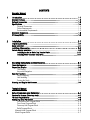
CONTENTS
Operator Manual
1
Introduction ............................................................................................... 1-1
Standard Features ......................................................................................................... 1-2
Optional Accessories ..................................................................................................... 1-3
Specifications ............................................................................................................... 1-4
Physical Dimensions............................................................................................. 1-4
Power Requirements ............................................................................................. 1-5
Environmental Requirements .................................................................................. 1-5
Standards Compliance ................................................................................................... 1-6
RF Susceptibility ............................................................................................................ 1-6
2
Installation ................................................................................................ 2-1
Unpacking and Setup..................................................................................................... 2-1
Scale Installation ........................................................................................................... 2-1
Installtion of Accessories………..………………………………………………………….… 2-8
Remote Display Installation ............................................................................................ 2-8
Installing the Ball or Roller Top Transfer Platter ..................................................... 2-11
Installing PS90 Conveyor Drop in Kit ................................................................... 2-11
3
Operating Instructions and Maintenance ........................................................ 3-1
Power Up Sequence ...................................................................................................... 3-1
Keypad and Display ...................................................................................................... 3-2
The Display .......................................................................................................... 3-2
Keys and Navigation ............................................................................................. 3-2
Operator Functions ........................................................................................................ 3-3
Parcel Weighing ................................................................................................... 3-3
Unit Switching ...................................................................................................... 3-3
Zeroing the Scale .................................................................................................. 3-3
Cleaning and Regular Maintenance ................................................................................. 3-4
Technical Manual
4
Setup Parameters and Calibration ................................................................ 4-1
Remove Cal Jumper (Metrology lock) .............................................................................. 4-1
PS Scale Program Menu ................................................................................................ 4-2
Configuring Setup Parameters ......................................................................................... 4-3
Push Button Zero Program Block ............................................................................ 4-4
Zero Cursor Program Block .................................................................................... 4-4
Power-up Unit Program Block ................................................................................ 4-5
Build Program Block ............................................................................................. 4-5
Alternate Units Program Block .................................................................................... 4-6
Mode Program Block................................................................................................. 4-7
Filter Program Block ..............................................................................................4-7
Baud Program Block ..............................................................................................4-7
ASCII Program Block ..............................................................................................4-8
Parity Program Block .............................................................................................4-8
Stop Program Block ...............................................................................................4-8
Protocol Program Block..........................................................................................4-8
Sleep Program Block .............................................................................................4-9
GeoCal™ Program Block .......................................................................................4-9
Calibration Weight Program Block ...........................................................................4-9
Calibration Program Block ....................................................................................4-10
End Program Block ..............................................................................................4-11
Metrology Seal Installation ............................................................................................ 4-12
5
Service and Repair .................................................................................... 5-1
Troubleshooting .......................................................................................................... 5-1
Error Code Section .............................................................................................. 5-2
Wall Transformer ................................................................................................ 5-2
Blank Display .................................................................................................... 5-3
No Keypad Interaction ......................................................................................... 5-3
Indicator Locked ................................................................................................. 5-3
Serial Communication Test ........................................................................................... 5-4
Update Processor or Scale Software............................................................................... 5-7
Replace Main PCB ...................................................................................................... 5-8
Load Cell Replacement ................................................................................................ 5-9
Installing the Base Mounted Display ............................................................................ 5-11
Appendix A: RS232 Host Interface ........................................................................ A-1
Communication Parameters ......................................................................................... A-1
Protocols ................................................................................................................... A-1
ASCII Characters and Conversions.............................................................. A-2
Toledo Protocol Host Commands ............................................................... A-4
Scale Status Byte Format.............................................................................................. A-5
Scale Confidence Byte Format ....................................................................................... A-5
Calibrate Using Host Interface ....................................................................................... A-6
Configure Scale Parameters Using Host Interface ............................................................. A-7
Appendix: USB Host Interface .............................................................................. B-1
References ................................................................................................................. B-1
Hardware ................................................................................................................... B-1
Electrical Connection ..................................................................................................... B-1
Power ....................................................................................................................... B-2
Protocol ..................................................................................................................... B-2
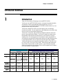
Chapter 1: Introduction
OPERATOR MANUAL
1
Introduction
Thank you for purchasing a PS shipping scale from METTLER TOLEDO.
The PS scale, like all METTLER TOLEDO products, is designed for maximum durability
and reliability in even the most demanding shipping applications. The PS is
manufactured in one of METTLER TOLEDO’s ten ISO 9000 certified facilities so you are
assured to receive a high-quality product.
The PS scale is designed for robust use in parcel shipping, mail, and other light
industrial environments. PS scale models have a wide temperature and humidity range
and can be used on most unheated shipping docks.
The PS scale is a low profile, high precision scale designed to meet the needs of the
legal-for- trade parcel/manifest markets. The PS scale is capable of communicating
through Mettler Toledo standard and SICS protocol or in the protocols of the major
shipping carriers. The scale program can be customized or quickly programmed in a
one step process through default communication settings of the major shipping carriers.
For preconfigured models, set up is simple and easy with plug and play capability.
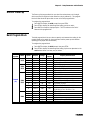
The PS scale family has 4 main models with maximum capacity at 15 kg (30 lb), 30
kg (70 lb), 60 kg (150 lb) and 150 kg (300lb). There are three postal versions with
high resolution to process letters as well as parcels. Typical PS models and platter
options are summarized in the chart below. See the “Build” program block in Chapter 4
for the exact capacity / increment options.
Letter & Parcel
Provides high resolution required for shipping via USPS &
Parcel Carriers
Capacity
Readability
PS15
PS3L
PS6L
30 lb
15 kg
70 lb
30 kg
150 lb
(lb only)
0-15lb x 0.1oz
0-7lb x 0.1oz
7-70lb x 0.2oz
0-10lb x 0.1oz
10-70lb x 0.2oz
70-149lb x 0.5oz
0-3kg x 0.001kg
3-15kg x 0.005kg
0-15kg x 0.005kg
15-30kg x 0.01kg
0-5lb x 0.005lb
5-25lb x 0.05lb
25-150lb x 0.1lb
ABS Plastic
ABS Plastic
Stainless Steel
ABS Plastic
Stainless Steel
Ball Top
USB
RS-232
USB
RS-232
EC / OIML
NTEP / UL
NTEP / UL
15-30lb x 0.2oz
Platter
Construction
PC Connection*
Approvals
Parcel
Superb reliability for retail stores, mail rooms and shipping
departments sending packages via Parcel Carriers or Truck Lines
PS15
PS30
PS60
PS90 (150 lb)
PS90 (300 lb)
30 lb
15 kg
0.01lb
0.005kg
70 lb
30 kg
150 lb
60 kg
150 lb
90 kg
300 lb
150 kg
0.05lb
0.02kg
0.05lb
0.02kg
0.05lb
0.02kg
0.1lb
0.05kg
Stainless Steel
Ball Top
Roller Top
Stainless Steel
Ball Top
Roller Top
USB
RS-232
USB
RS-232
NTEP / UL
Measurement
Canada
NTEP / UL
Measurement
Canada
ABS Plastic
ABS Plastic
Stainless Steel
USB
RS-232
USB
RS-232
USB
RS-232
NTEP / UL
EC / OIML
NTEP / UL
NTEP / UL
ABS Plastic
Stainless Steel
Ball Top
Roller Top
USB
RS-232
EC / OIML /
NTEP
Measurement
Canada / UL
1-1 (08/09)
METTLER TOLEDO PS Shipping Scale: Operator Manual
The PS90 and the PS60 both have 60 kg (150 lb) capacities. The PS90 (150 lb)
version is utilized for the applications that need a larger platter size.
PS6L, PS3L, and version of the PS15 have multi-interval technology for high
resolution, auto-ranging scales that are approved as weight classifiers for letters as well
as parcels. It is like having multiple scales in one.
Additional Information can be gotten from the MT website to help in installation and
operation of the scale:
www.mt.com/ind-psscale
In the unlikely event you experience difficulties operating your scale, please contact your
local distributor or METTLER TOLEDO representative from whom you purchased the
scale.
Standard Features
The following are standard features built into each PS shipping scale.
High quality Mettler Toledo precision load cell that is capable of being
programmed for Lb, Kg or both (Units are selectable with the Units key)
Multi-interval capacities that provide better weight resolution at the lower
range. Scale has auto range capability to automatically switch between
intervals.
GeoCal Setup compensates the sensitive factory calibration for local
gravitational differences, eliminating the expense of an onsite calibration.
0270, 2-key display for easy to read weight indication and programming of
the scale.
Capable of communicating via USB or RS232. For USB, the PS scale uses
the POS HID scale protocol.
Selectable communication protocols to match major carrier or manifest
software’s
USB Cable (6 ft)
RS-232 serial interface cable (10 ft)
Universal Power adapter with localized plug (Used with RS232
communication only, Scale is self powered through USB connection)
The following features are specific to the following PS models:
PS15:
30 lb / 15 Kg capacity
Coated steel plate for base and sub-platter
Base mounted display
Plastic platter
1-2 (08/09)
Chapter 1: Introduction
PS30:
70 lb / 30 Kg capacity
Die-cast aluminum base and sub-platter
Base mounted display
Plastic or stainless steel platter
PS60:
Standard Capacity 150 lb / 60 Kg
Die-cast aluminum base and sub-platter
Base mounted display
Stainless steel or plastic platter
PS90:
150 lb / 60 Kg or 300 lb / 150 Kg capacity
Painted steel base and sub-platter
Display bracket with 14 ft cable where display can be base mounted or wall mounted
Platter is typically packaged in a separate box.
Optional Accessories
Roller Top transfer platter (PS60 and PS90) used for conveyor applications that
allows easy movement of package in bi-directional (right-left) motion.
Ball Top transfer platter (PS60 and PS90) that allows easy rotation of package on
the platter.
Rail brackets (PS90) for mounting within conveyor section
Display Options :
o Single wall mount display with 14 ft cable, replaces the base display
o Single tower display with 14 ft cable for counter top mounting, replaces the base
display.
o Dual wall mount displays with 6 ft cable, replaces the base display
o Dual display tower with 10 ft cable for counter top mounting, replaces the base
display
o 2nd display, wall mounted with 10 ft Y cable. Used in conjunction with base
display.
o 2nd display, tower mounted with 10 ft Y cable. Used in conjunction with base
display.
o Display cable extension kit, 14 ft with impedance
o RS232 extension cable, 10 ft with male / female adapters
o 10 ft USB cable, replaces current USB cable
1-3 (08/09)
METTLER TOLEDO PS Shipping Scale: Operator Manual
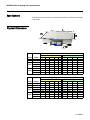
Specifications
The PS shipping scale conforms to and operates best within the specifications described
in this section.
Physical Dimensions
Model
Platter
PS15 Plastic
PS30 Plast, SS
Plast, SS
PS60 Ball Top
Roller Top
SS
PS90 Ball Top
Roller Top
Model
Platter
PS15 Plastic
PS30 Plast, SS
Plast, SS
PS60 Ball Top
Roller Top
SS
PS90 Ball Top
Roller Top
Wt
8
12
12
19
24
44
54
53
Weight (lb) and Dimensions (inches)
Scale
Shipping Box
L
W
H
D
Wt
L
W
11.6 10.9 3.5
2
11
16
14
13.9 12.3
4
2
17
19
18
13.9 12.3
4
2
17
19
18
13.9 12.3 5.2
2
23
19
18
17 17.6 5.8
0
31
22
19
20.5 16.5 4.25 2.3
53
27
22
19.8 15.8 4.8 2.6
65
27
22
22.8 17.5 6.1
2
63
27
22
H
8
10
10
10
17
12
15
16
Wt
3.6
5.5
5.5
8.6
10.9
20.0
24.5
24.1
Weight (kg) and Dimensions (mm)
Scale
Shipping Box
L
W
H
D
Wt
L
W
295 277 88.9 51
5.0
406
356
353 312 102 51
7.7
483
457
353 312 102 51
7.7
483
457
353 312 132 51
10.5 483
457
432 447 147 0
14.1 559
483
521 419 108 58
24.1 686
559
503 401 122 66
29.5 686
559
579 445 155 51
28.6 686
559
H
203
254
254
254
432
305
381
406
1-4 (08/09)
Chapter 1: Introduction
Power Requirements
The PS operates over an input voltage range of 7.5 to 14 VDC, at a current of 100 mA
or less.
For USB operation, the scale is powered through the USB port. With the low power
consumption, the PS scale is within the USB power requirements for connection to
your PC. Please connect scale directly to PC. Do not connect to a USB hub
An external 9 VDC power supply is required for power to the PS scale for
standalone applications or RS232 applications. The scale must be powered by the
universal power supply located in the scale’s shipping box. The wall mounted
transformer is rated between 110-220V and 50-60 Hz. The power supply may
have multiple plug adapters that can be clipped to the transformer based on
available outlets.
The power supply is not required for USB. If the power supply is connected during
USB operation, the scale will automatically sense the external power supply and
utilize it for the scale power.
Environmental
Requirements
The PS scale is designed to operate in conditions of 10-90% relative humidity, noncondensing, and a temperature range of:
PS15: 10° to +40°C (+14° F to +104°F)
PS30: 10° to +40°C (+14° F to +104°F)
PS60: 10° to 40C (+14F to +104F)
PS90: 10° to 40C (+14F to +104F)
PS6L: +10° to +40°C (+14F to +104F)
PS3L: 10° to +40°C (+14F to +104F)
The shipping and storage temperature range is 20° to 60C (-4F to +140F) at 0 to
95% relative humidity, non-condensing.
The scale is designed for use in parcel shipping and other light industrial environments.
This unit is not intended for dusty conditions, wash down or hazardous area operation,
nor for operation in environments of extreme heat, cold, or humidity (outside of the
range listed above for each model).
1-5 (08/09)
METTLER TOLEDO PS Shipping Scale: Operator Manual
Standards Compliance
PS15: meets or exceeds USA NIST HB-44, EC and international OIML requirements
for a 3000 division, Class III parcel scale.
PS30: meets or exceeds USA NIST HB-44 for a 1400 division Class III parcel scale.
PS60: meets or exceeds USA NIST HB-44, Australian NSC, Canadian MC, EC and
international OIML requirements for a 3000 division, Class III parcel scale.
PS3L meets or exceeds USA NIST HB-44 requirements for a 0-7lb / 7-70lb
(1120d/5600d) Class III multi-interval scale
PS6L meets or exceeds USA NIST HB-44 requirements for a 4800 division, Class III
parcel scale.
PS90: meets or exceed USA NIST HB-44 and Canadian MC for a 3000 division,
Class III parcel scale.
The PS scales has been tested and found to comply with the limits for a Class A
computing device pursuant to Subpart J of Part 15 of FCC Rules.
RFI Susceptibility
The PS scale meets the requirements of the European Norm. 45501 for RFI susceptibility
as listed below with a maximum of one display increment of change when calibrated for
recommended builds.
Radio Interference Frequency
Field Strength
26-1000 MHz
3 volts/meter
1-6 (08/09)
Chapter 1: Introduction
1-7 (08/09)
FOR YOUR NOTES
Chapter 2: Installation
.
2
Installation
This chapter gives detailed instructions and important information you will need to
install the PS scale successfully. Please read this chapter thoroughly before you begin
installation. This information is also covered in the PS Quick Start Guide.
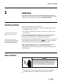
Unpacking and Setup
Please inspect the package as the carrier delivers it.
If the shipping container is damaged, check for internal damage and file a freight
claim with the carrier if necessary.
The proper environment enhances
the operation and longevity of the
scale.
If you choose to dispose of the
package, please recycle the materials.
The packaging is recyclable natural
fiber with biodegradable adhesives.
If the container is undamaged, open the box, remove the scale, and place it on a
solid, flat surface.
Please keep the packing material and shipping insert in case the scale needs to be
returned to METTLER TOLEDO. The PS is a precision instrument and may be
permanently damaged if not shipped in factory-approved packaging.
Open box and remove the packaging material from each side of the scale. Remove the
scale by grasping the bottom sides of the scale. Do not lift the scale by grasping the
sub-platter. Remove any protective shipping materials under the platter.
Locate a suitable environment for the scale. The scale will need to be placed on a
sturdy, level surface. Refer to Chapter 1 for environmental specifications. If
communication to the PC will be serial RS232, the scale will need to be located by an
AC outlet for power.
Scale Installation
WARNING!
AC power sources must have proper short circuit and
over current protection in accordance with local and
national electrical regulations. Failure to provide this
may result in bodily injury and/or property damage.
The PS shipping scale is fully assembled at the factory and ready for installation.
1. Check box for Contents. The following items should be in each package
2-1 (08/09)
METTLER TOLEDO PS Shipping Scale: Operator Manual
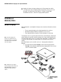
Typical package contents for the PS15 include:
Scale Base & Display
Platter
USB Cable – 6 ft
For USB connection to PC
Power
RS232
Supply
Cable – 10 ft
For Serial connection to PC
Typical package contents for the PS60, 6L, 30, and 3L include:
Scale Base & Display
Platter
USB Cable – 6 ft
For USB connection to PC
RS232
Power
Cable – 10 ft
Supply
For Serial connection to PC
Typical package contents for the PS90 include:
Scale Base
Platter
Packaged in separate box
USB Cable – 6 ft
For USB connection to PC
Display – Base / wall mount
Adhesive Pad
Cable – 14 ft
Clips
Power
RS232
Cable – 10 ft
Supply
For Serial connection to PC
2-2 (08/09)
Chapter 2: Installation
2. For the PS60, PS6L, PS30, PS3L, and PS15, go to step 3.
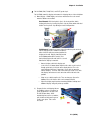
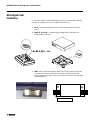
For the PS90, mount the display and remove the shipping tabs as instructed below:
a) Mount display – PS90 Display can be base mounted on the scale or wall
mounted. Choose one method.
Base Mounted: With black plastic clips in the insert position, attach
display to the base by inserting the plastic clips at yellow arrows indicated
below. Turn the plastic clips 90 degrees to lock into position.
Wall Mounted: Remove liner on one side of the adhesive pad and insert
into the display bracket. Remove liner from the
other side of the adhesive pad and position the
display on the wall. Display should be located
on the bottom portion of the bracket. Press
bracket firmly against the wall until it is secured.
Now that the display is mounted:
o
Connect display cable to the display and
scale at the 2 red arrows above. Note that the cable can be inserted
through guide holes in the back of the display bracket. The scale
connector panel will have 4 connectors. Insert cable at connector
labeled “Display”. The male cable connectors have a tab. Press cable
into display connector and scale connector until the tab locks into
position.
o
Wrap excess cable beneath scale. There are two grey clips on the
bottom of the scale that the cable can be wrapped around.
o
Adjust the display angle based on mounting position. Grab top and
bottom of display and gently rotate up or down.
b) Remove the four red shipping tabs on
the PS90 by using a screw driver to
gently pry apart the scale base until
the tabs become loose. While
maintaining force on the screwdriver,
pull the tabs out with your fingers or
needle- nose pliers. Tabs can be
discarded.
2-3 (08/09)
METTLER TOLEDO PS Shipping Scale: Operator Manual
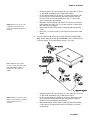
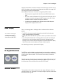
3. Level the scale by turning the adjustable feet on the bottom of the unit. The scales
are equipped with a level bubble. When the bubble is within the circle in the bubble
indicator, the PS scale is level. The feet must be adjusted so the scale is stable and
does not rock. On the PS90, tighten locking nut on feet.
Correct Level
Incorrect Level
- Bubble is completely
within circle
- Bubble is outside
circle
4. Place Platter on the scale. The platter is held in place by compression fit with the
rubber grommets on the spider
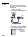
5. Confirm the connection method to the PC for communication. USB and RS232
configurations are possible. Choose one method only.
USB
o
o
or
RS232
USB is preferred if the Shipping / Carrier manifest system supports and
designates the scale for USB set up. Consult Carrier Software documentation for
details.
USB method must be used if the scale is to communicate with multiple
Shipping programs.
6. Connect Scale to PC by method chosen in step 5. Connect one method only.
DO NOT connect both USB and RS232 cables. Use one or the other!
2-4 (08/09)
Chapter 2: Installation
6a
USB Connection - Preferred
Plug small end of the USB cable into the scale connector port marked “USB”.
o For PS60, PS6L, PS30, PS3L, and PS15 turn the scale over to
access the scale connector ports.
o For the PS90, the connector port is located behind the display and
slightly under the platter.
Plug large end of USB cable into the PC. A direct connection to the computer
is required. Do not use a USB Hub.
Power Supply is not required since the low power requirements of the PS
scale is adequately powered through the USB port of the computer.
PC Connectors
Note: PS90, PS15 Connectors are
labeled in the reverse direction
Power Supply not
required.
Note: If additional cable length is
needed, a 10 ft USB cable 64057361
is available. This is a replacement
cable and not an extension cable
Direct Connect – No USB Hubs
The MT power supply can be utilized with the USB if your PC is having issues. The scale
will recognize this power adapter and utilize it as the power supply instead of the USB
port.
6b
RS232 Connection - Alternative
Plug the small connector of the RS232 cable into the scale connector
port marked “RS232”.
o For PS60, PS6L, PS30, PS3L, and PS15 turn the scale over
to access the scale connector ports.
o For the PS90, the connector port is located behind the
display and slightly under the platter.
Plug the small end of the Power Supply into the scale port marked
“Power Supply”
Go to the PC computer and locate the serial connector (typically
labeled COM 1, COM A or IOIOI).
Plug the large connector on the RS232 cable into the PC serial
connector
Plug the Power Supply into an AC outlet.
2-5 (08/09)
METTLER TOLEDO PS Shipping Scale: Operator Manual
AC
Outlet
PC Connectors
Note: If additional cable length is
needed, a 10 ft RS232 extension
cable 0900-0322-000 is available.
Power Supply required with RS232 Cable.
If you plugged the RS232 cable into the incorrect PC port, turn off the computer
first, then change ports and reboot your computer.
If additional cable length is needed, see replacement parts for 10 ft. RS232
extension cable with appropriate connectors.
Polarity of the power supply connector jack must match the scale; Use only the
Mettler Toledo Power Supply to energize the scale.
7. Enter GeoCal Set up code.
The patented GEOCAL™ feature provides the best scale accuracy. The GeoCal
feature precisely compensates for gravitational differences between the factory
location (where the scale was calibrated) and the scale’s point of use location.
Since the Earth’s gravity varies based on latitude and altitude, the GeoCal feature
allows the PS scale to maintain the sensitive factory calibration to ensure the most
accurate weighting results.
Observe the Display on the very first power up
Note: If the GEOCAL™ capabilities
of your PS unit have been
activated, the scale will only
prompt for the “Geo in” code on
the first power up
o
If 0.00 is displayed than the GeoCal is not activated. No code is required. Go
to step 8. For the best accuracy, scale should be calibrated on site by a trained
technician with certified weights.
o
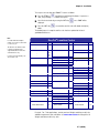
If “GEo in” is displayed, than enter the two digit GeoCal Location Code for the
area that the scale will be used. See the chart below for the correct code.
Note: If you missed entering the
GeoCal code on the first power up,
see Chapter 4 to reset the feature
for the next power up.
2-6 (08/09)
Chapter 2: Installation
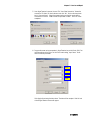
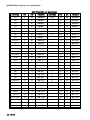
The sequence for selecting your GEOCAL™ code is as follows:
a) Press the ZERO key
repeatedly to scroll through the Codes. If you miss a
code, keep scrolling since numbers will repeat
b) Select the desired code by pressing the UNITS key
displayed.
c) Press the UNITS key
0.00.
once. DONE will be
a second time and the scale will reboot and display
The GeoCal process is complete and the scale has been updated for the local
gravitational differences.
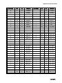
Note:
For states that have multiple
listings, choose the location that
is closest to you.
The GeoCal code within a state
is based on latitude and is
segmented between north and
south directions only.
Locations near a boundary can
chose either code.
GeoCal® Location Codes
State
Code State
Alabama
Birmingham & North
South of Birmingham
Alaska
Anchorage & South
Anchorage – Kotzebue
North of Kotzebue
Arizona
Phoenix & North
South of Phoenix
Arkansas
California
North of Chico
Chico – San Francisco
San Fran. - Bakersfield
South of Bakersfield
Colorado
Denver & North
South of Denver
Connecticut
Delaware
Florida
West Palm Beach & North
South of West Palm Beach
Georgia
Hawaii
Idaho
North of Salmon River Mt.
South of Salmon River Mt.
Illinois
Bloomington & North
South of Bloomington
13
12
23
26
27
12
11
13
16
15
14
13
13
12
16
15
11
10
12
9
17
16
16
15
Indiana
North of Indianapolis
Indianapolis & South
Iowa
North of Des Moines
Des Moines & South
Kansas
Kentucky
Louisiana
Maine
Maryland
Massachusetts
Michigan
NW of Lake Michigan
SE of Lake Michigan
Minnesota
Mississippi
Kosciusko & North
South of Kosciusko
Missouri
North of Springfield
Springfield & South
Montana
Helena & North
South of Helena
Nebraska
Nevada
New Hampshire
New Jersey
New Mexico
New York
Albany & North
South of Albany
Code State
16
15
17
16
14
14
12
18
15
17
18
17
18
13
12
15
14
18
17
15
13
17
16
11
17
16
North Carolina
Raleigh & North
South of Raleigh
North Dakota
Ohio
Akron & North
South of Akron
Oklahoma
Oregon
Salem & North
Salem - Oakridge
South of Oakridge
Pennsylvania
Rhode Island
South Carolina
South Dakota
Tennessee
Texas
NE of Colorado River
SW of Colorado River
Utah
Vermont
Virginia
Washington, DC
Washington State
West Virginia
Wisconsin
Green Bay & North
South of Green Bay
Wyoming
North of Casper
Casper & South
Code
14
13
18
16
15
13
18
17
16
16
16
13
17
13
12
11
13
17
14
15
18
15
18
17
15
14
For Legal - For - Trade applications, contact your local Weights and Measure office for
additional requirements and certification. See www.ncwm.net/state for listing of the US
Weights and Measure offices by state.
2-7 (08/09)
METTLER TOLEDO PS Shipping Scale: Operator Manual
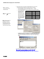
8. Configure the Carrier or Shipping software on the PC to communicate with the
scale. Open your carrier or shipping software and go to the Set Up screen. Select
the proper scale model from the pull down list. (Example: Toledo PS60).
For additional assistance, contact the shipping software provider.
Installation of
Accessory Items
Remote Displays
Mettler Toledo offers several options for displays: base mounted, wall mounted, or tower
mounted.
o
o
o
Note: The remote displays are
typically not used with the PS15
since the package size is generally
small and it does not obstruct the
view of the display.
The base mounted display has the display mounted to the scale base.
Wall mounted displays allow the weight to be seen at eye level.
Tower mounted display is typically used for mounting on a counter top.
The majority of scales are generally ordered with a base mounted display. Remote wall
or tower displays are typically used where package size is large enough to obstruct the
view of the display on the scale. For “Legal for Trade” applications, a customer display
is required in most locations and remote displays are used many times for better
visibility.
One or two displays can be used with each scale. Display options allow for the
following:
a) A 2nd wall mounted (0270-5X00-000) or tower mounted display (02707X00-000) can be added in parallel to the base display with the use of a 10 ft
Y cable. To install this option:
Note: If additional cable length is
needed, a display cable extension kit
0901-0504-000 is available. Kit
includes 14 ft cable and in-line
adapter.
2-8 (08/09)
Chapter 2: Installation
o
o
o
Safety: Make sure any excess cable
is properly secured and does not
provide a trip hazard for personnel or
customers
o
o
Disconnect power to the scale and locate the scale connectors: PS15, 30,
3L, 60, and 6L on bottom of scale, PS90 under the platter.
For the connector marked “Scale display”, disconnect base display cable
by pressing in the latching tab on the jack while pulling the cable out.
Insert the jack of the 6 inch long portion of the 10 ft “Y” cable into this
same “Scale Display” connector port.
Now connect the base display cable into one end of the In-line female-tofemale adapter, and connect the 12 inch long end of the Y-cable into the
other end of the In-line adapter.
Mount remote display (Wall or Tower) in proper location with mounting
screws.
Connect the 114” long end of the Y-cable into the back side of the remote
display.
b) If the base display is not desired, then a single wall mounted (0270-3X00000), or tower mounted displays (0270-2X00-000) can be substituted for the
scale base display. These remote displays include a 14 ft cable.
Note: If additional cable length is
needed, a display cable extension kit
0901-0504-000 is available. Kit
includes 14 ft cable and in-line
adapter.
o
Safety: Make sure any excess cable is
properly secured and does not provide
a trip hazard for personnel or
customers
o
o
Disconnect power to the scale and locate the scale connectors: PS15, 30,
3L, 60, and 6L on bottom of scale, PS90 under the platter.
For the connector marked “Scale display”, disconnect base display cable
by pressing in the latching tab on the jack while pulling the cable out.
Remove the screws mounting the Base Display
Mount remote display (Wall or Tower) in proper location with mounting
screws. Connect the Display Cable into the Scale Display Jack and the
remote display.
2-9 (08/09)
METTLER TOLEDO PS Shipping Scale: Operator Manual
c) If two displays are needed and the base display is not desired, than a dual
wall mounted display (0270-4X00-000 with 6 ft cable), or a 2 sided tower
display (0270-6X00-000 with 10 ft cable) can be substituted for the scale
base display.
Note: If additional cable length is
needed, a display cable extension kit
0901-0504-000 is available. Kit
includes 14 ft cable and in-line
adapter.
o
Safety: Make sure any excess cable
is properly secured and does not
provide a trip hazard for personnel or
customers
o
o
Disconnect power to the scale and locate the scale connectors: PS15, 30,
3L, 60, and 6L on bottom of scale, PS90 under the platter.
For the connector marked “Scale display”, disconnect base display cable
by pressing in the latching tab on the jack while pulling the cable out.
Remove the screws mounting the Base Display.
Mount remote display (Dual Wall or Tower) in proper location with
mounting screws. Connect the Display Cable into the Scale Display Jack.
2-10 (08/09)
Chapter 2: Installation
Installing the Ball
and Roller Top
Transfer Platter
A ball top or roller top transfer platter is available for the PS60 and PS90. To install the
ball or roller transfer platter:
1. Remove the platter supplied with the PS. PS90 can be ordered without a platter.
2. Place the ball or roller top transfer platter on the PS scale.
3. Ensure that the ball or roller top transfer platter drops into place without mechanical
interference.
Note: If the unit fails to capture zero, reboot the scale by cycling power (unplug the
Wall transformer and/or USB cable). Reconnect the power source. If the scale still fails
to capture zero, re-calibration will be required.
Installing Conveyor
Drop in Kit for PS90
The Conveyor drop in kit includes two adjustable width rail brackets that allow a PS90
scale to be integrated into a standard gravity conveyor, between 22 and 32 inches. The
kit is designed for standard conveyors that use 1.9” diameter rollers on a frame that
supports 1.5” spacing increments.
For Conveyor Drop-In-Kit
64058112:
Reference detailed instruction set
64058111 inside shipping box or
obtain copy on
www.mt.com/ind-psscale.
!
WARNING! DO NOT ATTEMPT TO INSTALL THIS KIT IN A POWERED
CONVEYOR.
The PS90 scale can be mounted lengthwise or transverse in the conveyor frame for the
Ball Top Platter. The ball-top platter
allows packages to be rotated easily
when on the scale. This option is
commonly used when packages have
labels that must be scanned at the
shipping station.
The PS90 scale should always be
mounted lengthwise when used with
the roller-top platter. The roller-top
platter is commonly used when
packages are significantly larger than
the scale.
2-11 (08/09)
FOR YOUR NOTES
Chapter 3
3
Operating Instructions and Maintenance
Operating Instructions and Maintenance
This chapter gives information that an operator will need to become familiar with the
scale and perform its functions in normal operating mode. Before weighing parcels, the
PS Scale should be configured properly and make sure power is applied as instructed
below. How the scale operates is based on the parameter settings in the set up
program. See Chap 2 for installation instructions and Chap 4 for advanced
programming of the set up parameters.
Power-up Sequence
To power up the scale, apply power to the unit:
Note: On most models, the I/O button
is disabled and the scale is energized
whenever power is applied to it, and
de-energized when power is removed.
Note: Power supply is not needed for
USB connection to a PC since the
power requirements are within
standard USB specifications. If the
power supply is used with the USB,
the scale will recognize the power
adapter and use it as the power
source.
o
o
USB communication: Plug in USB cable to an energized PC.
RS232 communication – Plug in power adapter to an AC outlet.
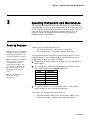
The PS goes through a power-up sequence each time power is applied. The scale
performs a diagnostic test on its ROM and RAM, and then proceeds to the normal
operating mode. The power-up sequence is as follows:
1. All segments of the display characters are activated. This verifies operation of all
display segments.
2. The scale displays the software part number followed by the software revision
status. Software numbers for the standard PS models are:
Model
PS15
PS30
PS3L
PS60
PS6L
PS90
Note: Special software version
may be used for specific
applications
SW Number
170700
170640
170640
170702
170702
174509
3. The scale then captures zero (if the zero reading is within 10% calibrated
capacity on power-up) and is ready for normal operation.
To turn off the scale, unplug the power source to the scale:
o
o
USB communication: unplug the USB cable (and power adapter if used).
RS232 communication – unplug the power adapter from AC outlet.
3-1 (08/09)
METTLER TOLEDO PS Shipping Scale: Operator Manual
Keypad and Display
The PS scale has a simple LCD weight display with two keys that are used to perform
scale functions. Keypad is used for operation of the scale as well as entering set up
parameters. Weight is displayed using numeric characters with decimal point and
comma. Cursors (horizontal bars) at the bottom of the display indicate current weight
units, weight range, and zero condition when zero is captured.
The Display
Curser will indicate the weight range
on Multi-Range models. Range
indication is not needed with MultiInterval models that have autoranging capability.
The PS scale display consists of six digits and five cursor positions. Each digit is
composed of seven segments and is 12 mm high. The PS’s cursor can appear above
one or more of the legends printed on the display to indicate the current weight unit,
weight range, a stable condition, zero, or options in setup mode.
The display area also indicates over-capacity and under-capacity conditions. Over- and
under-capacity are indicated on the display as follows:
Under Capacity
Over Capacity
Keys and Navigation
The PS keypad contains a UNITS key
and a ZERO key
:
The functions for each key in normal operating mode are as follows:
UNITS - Press UNITS to switch between the selected
primary units and alternate units.
ZERO - Press ZERO to zero an empty scale.
The functions for each key in setup mode are as
follows:
UNITS - Press and hold UNITS for up to 8 seconds
to enter setup mode. When a program block option
is displayed for selection, press UNITS to confirm the selection.
ZERO - Press ZERO to scroll through a list of parameter options.
3-2 (08/09)
Chapter 3
Operating Instructions and Maintenance
Operator Functions
The PS scale is simple to operate and supports one primary function: parcel weighing.
With the two-key display, the operator has options for:
Unit switching
Zero the scale
Parcel Weighing
To weigh a package:
You may wish to recapture zero
periodically when the scale is in
continuous use. It is not necessary to
press ZERO before each transaction.
1. Press ZERO
to capture zero. The display reads 0.00 and a cursor appears
above the zero indicator in the legend.
2. Place the parcel to be weighed on the platter. The display reads the parcel weight
with a cursor above the corresponding units of weight (lb or kg).
3. Record the parcel weight as needed, then remove the parcel from the platter.
Unit Switching
The PS scale lets you view the displayed scale weight in primary and secondary units.
Alternate units must be enabled in setup mode (Alt in Chap 4) to convert and display in
alternate units. The primary units are also designated in set up. (unitS in Chap 4)
Some selections of the “build” in set
up, like Multi-Interval capacities, may
have unit switching inhibited. Only
option presented will be “disabled”.
To switch units:
1. With scale weight displayed, press the UNITS
key. The PS scale
automatically converts the displayed weight to weight in the alternate unit as
indicated by the cursor.
2. Press UNITS
again to switch the scale back to the primary units. The weight
shown on the display will be the primary units as indicated by the curser.
Zeroing the Scale
Most scales are set up to re-zero if
weight is within 2% of the scale
capacity. If the zero change exceeds
the 2% limit, the scale will not capture
zero. In this case, cycle power or
recalibrate.
Remove all weight and debris from the scale platter and press ZERO
to capture
the zero weight. The PS display will indicate a zero reading with the cursor. The scale
will re-zero provided the weight is within the designated % of the scale capacity as
programmed in set up (Pb = 0 in Chap 4).
If the scale does not capture zero with the above procedure:
1. Unplug the scale, remove all weight from the platter, make sure nothing is
touching the platter, and reconnect the power.
2. If cycling power does not work, recalibrate the scale per Chap 4.
3-3 (08/09)
METTLER TOLEDO PS Shipping Scale: Operator Manual
Cleaning and Regular
Maintenance
Based on environmental conditions, you may need to wipe the keypad and platter with
a clean, soft cloth that has been dampened with a mild cleaner. Do not use any type of
industrial solvent such as toluene or isopropanol (IPA). These may damage the display
finish. Do not spray cleaner directly onto the display terminal. Make sure no overspray
hits the cable connectors or circuit board.
The PS scale is basically maintenance free. Once a year, you can verify the weight and
the display readings.
o
If test weights are available, place a test weight on the scale and verify the
weight reading is correct. Test weight must be within the scale capacity range.
o
You can check the display to ensure all segments are functioning by cycling
the power to the scale. Unplug the power supply and/or the USB cable, wait a
few seconds until the screen is blank, and plug the scale back in. For the first
few seconds, all segments on the display will initially light up.
3-4 (08/09)
FOR YOUR NOTES
Chapter 4: Set Up Parameters and Calibration
TECHNICAL MANUAL
4
Setup Parameters and Calibration
This chapter discusses basic information and specific instructions for configuring each
program block of the PS scale, setting the operating parameters, and calibrating the PS
scale.
Legal-for-Trade Application
Note: Accessing the calibration
switch will require breaking the
Weights and Measure Seal if
already applied. Breaking the
Weights and Measure seal will
require re-certification of the scale
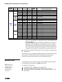
The scale’s interface program is shown in the quick overview map on the next page.
There are 17 functions or programming steps available, with two levels of access:
o Normal set up parameters that can be accessed by any operator
o Full access to all set up parameters with the removal of the metrology lock (IE:
calibration jumper or switch W1).
The functionality behind the Metrology lock is shown in the blue blocks on the program
overview map with a Lock Symbol
.
For a quick, one-selection SET UP process without calibration, the PS scale menu has a
specific default setting for each of the major Shipping Carriers (FedEx, UPS, DHL NA,
Purolator, etc). Go directly to the END function (Step 17) and select the default for the
carrier and the scale will automatically input the other parameters. Please use one of the
default settings if you do not wish to customize the parameter settings and you are not
calibrating the scale with test weights.
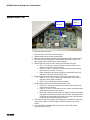
Remove Cal Jumper
To access the full program, the metrology lock will need to be set to the off position by
removing the Calibration jumper W1. To remove W1:
Disconnect power to the scale, remove the platter, and remove the PCB cover:
o PS60, PS30, PS3L, and PS6L – Cover is located behind the display and under
the spider that holds the platter. Use 9/32 socket or adjustable wrench to remove
bolt.
o PS15 – Turn scale over and remove bolt on plastic cover. Use 9/32 socket or
adjustable wrench to remove bolt.
o PS90 – PCB is located under stainless steel connector cover behind the display.
Remove two screws on left and
right side of cover.
Inside the cover, there is a W1 (blue
plastic) jumper indicated by the red
dashed circle in photo. Remove jumper
off of both prongs and replace jumper
on only one prong so it doesn’t get lost.
Replace cover loosely and place platter
back on the scale. Connect the power
source to the scale.
4-1 (08/09)
PS Scale Program Menu
Program
Step
Category
Display
Parameter listing
Metrology Lock
0.00
Units Key
Press and Hold Units Key for
8 Sec to enter setup mode
Setup
>0<
1
Set Range of Zero
button - % Capcity
>0<
Only shown while pressing Units after the 8 sec
Pb 0
>0<
2 PCt
Zero Key
>0<
5 PCt
100 PCt
Not available on all models or builds (IE: Multi-Interval)
nodE
>0<
2
Display indicator
for Center of Zero
0 CurS
Units at Power up
>0<
diSAbL
>0<
3
disable
>0<
Build Options - based on "Units" selected and PS Model
Metric
PoundS
Scale
PS15
>0<
4
Set Capacity
and Increments
buiLd
Alternate Unit
Switching - kg/lb
Alt
>0<
diSAbL
Weight Mode
nodE
Vibration Filter
FiLtEr
>0<
Use to Customize Serial set up
bAud
8
Select # Data Bits
ASCII Characters
ASCii
10
Parity Bit
nornAL
CLASFr
USPS
Round Up 1+
Only for PS30/3L
nEdiun
>0<
6
7
8
100-05
45-02
150-ni
60-ni
149-ni
60-05
149-ni
70-ni
200-ni
90-1
150-n5
60-nC
100-ni
45-ni
150-nC
HEAUY
Heavy
>0<
>0<
1200
>0<
2400
4800
>0<
9600
19200
>0<
SEUEn
>0<
5
>0<
>0<
Seven
4
15-nC
70-n0
>0<
Round Up 5+
300
PAr
Wt Classifier
3
30-n0
15-ni
70-ni
30-ni
100-n0
45-05
300-1
150-05
EHPAnd
LiGHt
>0<
>0<
2
30-005
15-002
70-nr
30-01
150-05
60-02
250-1
100-05
Expand Wt - 10x
Medium
Baud Rate
Normal
1
30-01
15-005
70-05
30-02
150-02
60-01
150-05
60-02
tESt
>0<
8
PS90U
EnAbLE
Units
Pounds
Metric(kg)
Pounds
Metric(kg)
Pounds
Metric(kg)
Pounds
Metric(kg)
Factory test
>0<
7
Based on Build selected
>0<
>0<
6
PS30
PS3L
PS60U
PS6L
See Build Chart
>0<
5
Note: 7 Segment Display is limited in alpha characters that
can be displayed (IE: No Letter "M" so "n" is used)
EnAbLE
nEtriC
unitS
Remove PCB Cover on top of scale
(Bottom for PS15)
Remove Blue W1 jumper on PCB
to access functionality
EiGHt
Mark
>0<
SPACE
>0<
nArC
>0<
>0<
odd
EVEn
None
Only shown if ASCii = Eight
Only shown if ASCii = Seven
>0<
11
# of Stop Bits
>0<
StoP
1
12
Protocol
Proto
2
>0<
>0<
diSAbL
Not available on lb-oz builds. Same for "def 1-6" in "End"
>0<
>0<
toLEdo
Proto 1
Proto 2
FEDEX
>0<
>0<
13
Power Saving mode
Select Models only
SLEEP
14
GeoCal
GEo in
15
Select Cal weights
CAL VT
diSAbL
>0<
>0<
WT SC320
WT SC3870
>0<
EnAbLE
Scale
PS15
PS30
PS3L
PS60U
PS6L
See Cal WT Chart
>0<
>0<
Calibration Mode
CAL
UPS
yES
no
PS90U
Empty
>0<
>0<
Proto 5
Proto 6
Purolator
Proto 7
DHL
MT-SICS
Function is inhibited on most models
>0<
16
Proto 4
5 minutes
5 nin
diSAbL
>0<
>0<
Proto 3
Any previous Set Up changes are now saved
Units
Pounds-lb
Metric-kg
Pounds-lb
Metric-kg
Pounds-lb
Metric-kg
Pounds-lb
Metric-kg
Calibration Weight Options
Cal 1
Cal 2
Cal 3
Cal 4
5
10
15
20
2
5
7
10
5
25
30
50
2
10
15
20
25
50
75
100
10
20
30
45
25
50
70
100
10
20
25
45
Displayed parameters based on UNITS selected and PS model
Add X WT
Done
>0<
17
Exit Setup
select Defaults
End
>0<
dEFALt
FedEx
Scale will exit Set Up mode, reboot and go to GeoCal if enabled
>0 <
>0<
Abort
SAUE
no
>0<
M Toledo
FedEx
>0<
Def 11
Exit
Scale reboots
dEF 1
UPS
>0 <
USPS
>0<
>0<
dEF 10
UPS OIML
dEF 9
Europost
dEF 2
MT Kg/Kg
dEF 3
WT SC320
>0<
dEF 8
>0<
>0 <
>0<
dEF 7
MT Lb/Lb
dEF 4
WT3870
UPS
>0<
dEF 6
DHL
DHL
dEF 5
Purolator
>0<
Chapter 4: Setup Parameters and Calibration
Configuring Setup
Parameters
WARNING
ONLY PERMIT QUALIFIED PERSONNEL TO SERVICE
THIS EQUIPMENT. EXERCISE CARE WHEN MAKING
CHECKS, TESTS AND ADJUSTMENTS THAT MUST BE
MADE WITH POWER ON. FAILING TO OBSERVE
THESE PRECAUTIONS CAN RESULT IN BODILY HARM.
Program Menu chart
Units Key - will accept the value
and scroll vertically to the next step.
Zero key - will move horizontally to
the next parameter value.
To exit the set up program early:
First Method
o Press the UNITS key repeatedly
until End is displayed.
o Press the ZERO key until SAVE
or Abort is shown.
o Press the UNITS key to accept
Second method
Disconnect the power from the
scale. Changes will not be saved.
To enter the setup mode, press and hold the UNITS key
for up to eight seconds
until the message Setup is displayed. Release the UNITS key, and the first function (PB
0) will be displayed.
To program the scale, use the two function keys as follows:
Units Key - will accept the current displayed parameter value and increment to the
next function (IE: program block or Step).
Zero Key - will scroll through the available parameters for a specified function,
(IE: program block or Step).
This section describes the program blocks that govern normal operation including:
Pb 0
0 CurS
unitS
buiLd
ALt
nodE
FiLtEr
bAud
ASCii
The 7 segment display is limited on
the Alpha characters that can be
displayed, (IE: no “m” can be
displayed so letter “n” is used
instead.
Push Button Zero Range*
Zero Cursor (indicator bar) *
Units displayed at Power-up *
Build (Capacity/Increment)*
Alternate Units (Switching)
Mode *
Filter
Baud Rate – RS232
ASCII – RS232
PAr
StoP
Proto
SLEEP
Geo in
CAL V
CAL
End
Parity –RS232
Stop Bits – RS232
Comm. Protocol –RS232
Sleep
GeoCal™ *
Cal Weight used*
Calibration *
End
* Items are locked by the Calibration Jumper W1
The PS scale can also be configured remotely through the METTLER TOLEDO Host
Interface. Details for configuring the scale using the Host Interface are given in the
Appendix at the end of this manual.
4-3 (08/09)
METTLER TOLEDO PS Shipping Scale: Technical Manual
As stated above, the PS scale can be
1. Customized by going through the menu and selecting each parameter
2. Default selection - the PS scale also has a quick, one-selection SET UP process for
each of the major carriers through the default selection in the End program block
(Step 17). Use a default selection if you do not wish to customize the parameter
settings. The default selection will automatically enter the other parameters.
To select a default setting;
Press the UNITS key repeatedly until End appears on the screen
Press the ZERO key repeatedly until the proper default selection is shown.
o
o
o
Not all default selections may be
available. Default selection is based
on the model ordered or “Build“
selected below.
o
o
o
Default – Mettler Toledo
Def 1 – FedEx
Def 2 – WT SC320
Def 3 – WT SC3870
Def 4 – UPS
Def 5 – Purolator
o
o
o
o
o
o
Def 6 – DHL / Airborne
Def 7 – MT for lb/lb
Def 8 – MT for kg/kg
Def 9 – Euro post
Def 10 – UPS OIML
Def 11 – USPS
Press the Units key again to accept the Default selection. Scale will update the
parameters and reboot.
To customize the parameter settings or to calibrate the scale:
Continue with the setup process below.
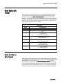
Push Button Zero
The 100% zero range can be used
as a tare function.
The Push Button Zero program block lets you configure the range the
key can be
used to capture zero. The ranges currently supported are ± 2%, ± 5%, and ± 100% of
capacity (Metrology PCB jumper must be removed). This range does not affect the zero
range when the scale is powered up.
To configure the program block:
1. Press UNITS to display the Pb 0 prompt, then press ZERO to access the options.
2. Press ZERO repeatedly until the desired zero capture range is displayed.
3. Press UNITS again to accept the pct option. The PS continues to the Zero Cursor
program block.
Zero Cursor
The Zero Cursor program block lets you enable or disable the center of zero indicator on
the PS display. (Metrology PCB jumper must be removed.)
To configure the program block:
1. Press UNITS to display the 0 CurS prompt, then press ZERO.
2. Press ZERO to display the desired approval setting, enable or disable.
3. Press UNITS to accept the displayed option. The PS continues to the Power-up Unit
program block.
4-4 (08/09)
Chapter 4: Setup Parameters and Calibration
Units at Power-up
The Power up Unit program block lets you select the scales primary unit of weight,
which would be the weight unit active when the scale is powered up. This program
block will effect the build options that are seen in the Build program block.
To configure the program block:
1. Press UNITS to display the unitS prompt, then press ZERO.
2. Press ZERO to display the desired approval setting, pounds or metric.
3. Press UNITS to accept the displayed option. The PS continues to the Build /
Alternate Units program block.
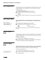
Build Program Block
The build program block lets you chose a capacity and increment size setting for the
product based on the model you have purchased and the power-up units selection.
(Metrology PCB jumper must be removed.)
To configure the program block:
1. Press UNITS to display the buiLd prompt, then press ZERO.
2. Press ZERO to display the desired approval setting. Options are dependent on the
unitS selected above and may vary as follows:
Powerup units
Model
PS15
PS30
PS3L
Pounds
(lb)
PS60
PS6L
PS90
Option
Display
Range
Unit
Switch
1
2
3
1
2
3
4
1
2
3
4
5
30-01
30-005
30-no
70-05
70-nr
70-ni
70-no
150-02
150-05
100-no
100-05
150-ni
S
S
MI
S
MR
MI
MI
S
S
MI
S
MI
Yes
Yes
No
Yes
No
No
No
Yes
Yes
Yes
Yes
No
6
149-ni
MI
No
7
150-n5
MI
No
8
100-ni
MR
Yes
1
2
3
4
5
6
150-05
250-1
300-1
S
S
S
Yes
Yes
Yes
30 x 0.01 lb
30 x 0.005 lb
0-15lb x 0.1 oz / 15-30 lb x 0.2 oz. .
70 x 0.05 lb
0-7 x 0.005 / 7-70 x 0.02 lb
0-7 x 0.01 / 7-70 x 0.02 lb
0-7lb x 0.1 oz / 7-70 lb x 0.2 oz. .
150 x 0.02 lb
150 x 0.05 lb
0-10 lb x 0.01oz / 10-100 x 0.5 oz
100 x 0.05 lb
0-60 x 0.02 lb / 60-150 x 0.05 lb
0-10 lb. x 0.1 oz, 10-70 lb. x 0.2 oz,
70-150 lb. x 0.5 oz
0-5 x 0.005 / 5-25 x 0.05 / 25-150 x 0.1 lb
0-10 lb x 0.01oz / 10-20 lb x 0.2 oz /
20-40 lb x 0.5 oz / 40-100 x 1 oz
150 x 0.05 lb
250 x 0.1 lb
300 x 0.1 lb
149-ni
200-ni
MR
MR
NA
NA
0-50 lb. x 0.5 oz, / 50-149 lb. x 2 oz,
0-50 lb. x 1 oz, / 50-200 lb. x 2 oz,
Capacity and Resolution
4-5 (08/09)
METTLER TOLEDO PS Shipping Scale: Technical Manual
Powerup units
Model
PS15
PS30
PS3L
Metric
(kg)
PS60
PS6L
PS90
Option
Display
Range
Unit
Switch
1
2
3
4
1
2
3
1
2
3
4
5
6
7
8
1
2
3
4
5
6
15-005
15-002
15-ni
15-nC
30-02
30-01
30-ni
60-01
60-02
45-05
45-02
60-ni
70-ni
60-nC
45-ni
60-02
100-05
150-05
150-nC
60-05
90-1
S
S
MI
S
S
S
MI
S
S
S
S
MI
MI
S
S
S
S
S
S
S
S
Yes
Yes
No
No
Yes
No
No
Yes
Yes
Yes
Yes
No
No
No
Yes
Yes
Yes
Yes
No
Yes
Yes
o
o
Capacity and Resolution
15 x 0.005 kg
15 x 0.002 kg
0-3 x 0.001 / 3-15 x 0.005 kg,
15 x 0.005 kg
30 x 0.02 kg
30 x 0.01 kg
0-15 x 0.005kg / 15-30 x 0.01 kg
60 x 0.01 kg
60 x 0.02 kg
45 x 0.05 kg
45 x 0.02 kg
0-30 x 0.01kg / 30-60 x 0.02 kg
0-50 x 0.02kg / 50-70 x 0.05 kg
60 x 0.02 kg,
0-45 x 0.05kg
60 x 0.02 kg
100 x 0.05 kg
150 x 0.05 kg
150 x 0.05 kg,
60 x 0.05 kg
90 x 0.01 kg
Range: S = Single Range, MR = Multi-Range, and MI = Multi-Interval with the
auto ranging ability.
Unit Switch: Yes means that unit switching is permitted and can be set in the
Alt program block below. No means unit switching is inhibited. Resolution
and increment size of the alternate units will be the same option number for
that PS scale model. PS60 in pounds with option 5 of 100-05 build will have
the capacity of 45 kg and 0.02 kg resolution when switching to metric units.
3. Press UNITS to accept the displayed option. The PS continues to the Alternate Units
program block.
Note: the scale can only be sealed for Weights and Measure in the build that is listed on
the data label. The PS6L and PS60 have the same listing on the display for the
selection of the capacity and increment size, but utilize different load cells.
Alternate Units
This program block lets you enable or disable unit switching during normal operation.
Unit switching must be permitted in the buiLd selection above.
Note: Resolution and
increment size of the
alternate units will be
the same option
number for that PS
scale model.
4-6 (08/09)
To configure the program block:
1. Press UNITS to display the ALt prompt, then press ZERO.
2. Press ZERO to display the desired approval setting, enable or disable.
3. Press UNITS to accept the displayed option. The PS continues to the Mode / Filter
program block.
Chapter 4: Setup Parameters and Calibration
Mode Program Block
The Mode program block lets you configure which mode is used to display weight.
(Metrology PCB jumper must be removed.)
To configure the program block:
If Test mode is accidentally
selected, scale will display dLC and
stay in that mode. To exit, remove
power from the scale, install Cal
jumper, and power up scale.
1. Press UNITS to display the nodE prompt, then press ZERO.
2. Press ZERO to display the desired mode. Options include:
Test – Used for manufacturing only.
Normal – Retail rounding: round up for values of 5+
Expanded – view expanded weight, typically view 10X resolution
Classifier – weight classifier rounding: round up for values 1+
USPS – USPS rounding for PS30 only
3. Press UNITS to accept the displayed mode option. The PS continues to the Filter
program block.
Filter Program Block
The Filter program block lets you configure the vibration noise filter that is used in
determining weight stability on the scale. The PS disregards environmental vibrations
that affect the weighing accuracy according to the filter setting.
To configure the program block:
Heavier filter settings increase the
time required for the scale to settle
on a stable weight.
1. Press UNITS to display the FiLtEr prompt, then press ZERO.
2. Press ZERO to display the desired noise filter. Options include:
Light
Heavy
Medium
3. Press UNITS to accept the displayed filter option. The PS continues to the Baud
program block.
Baud Program Block
This program block lets you set the baud rate for RS232 connection (the speed at
which data is transmitted in bits-per-second).
To configure the program block:
1. Press UNITS to display the bAud prompt, then press ZERO.
2. Press ZERO to display the desired baud rate. Options include:
300
4800
1200
9600
2400
19200
3. Press UNITS to accept the displayed baud rate option. The PS continues to the ASCII
program block.
4-7 (08/09)
METTLER TOLEDO PS Shipping Scale: Technical Manual
ASCII Program Block
The ASCII program block lets you select the number of data bits that make up an ASCII
character for RS232 connection. Most METTLER TOLEDO equipment communicates
using seven data bits.
To configure the program block:
1. Press UNITS to display the ASCii prompt, then press ZERO.
2. Press ZERO to display the desired bit selection. Options include:
Seven (7)
Eight (8)
3. Press UNITS to accept the displayed option. The PS continues to the Parity program
block.
Parity Program Block
Based on ASCII setting:
o ASCII = 7, options are Space,
Mark, Odd, and Even.
o ASCII = 8, options are None
The Parity program block lets you select the parity option for data transmission for
RS232 connection. Parity is an error checking mechanism. To configure the program
block:
1. Press UNITS to display the PAr prompt, then press ZERO.
2. Press ZERO to display the desired parity option. Options include:
Space
Even
Mark
None (Only if ASCii = 8)
Odd
3. Press UNITS to accept the parity option. The PS continues to the Stop program
block
Stop Bit Program
Block
The Stop Bit program block lets you select the number of stop bits to be transmitted for
each ASCII character for RS232 connection. Most METTLER TOLEDO products will work
with either 1 or 2 stop bits.
To configure the program block:
1. Press UNITS to display the StoP prompt, then press ZERO.
2. Press ZERO to display 1 or 2 stop bits, then press UNITS to accept the displayed
selection. The PS continues to the Protocol program block.
Protocol Program
Block
The Protocol program block lets you select a pre-configured set of scale commands for
RS232 connection. Protocols are configured in the factory according to your ordering
information. This section gives instructions on how to select a protocol only.
To select a protocol command set:
Proto1 through Proto 6 are not
available for lb-oz builds.
1. Press UNITS to display the Proto prompt, then press ZERO.
2. Press ZERO to display the desired protocol. Options include:
Toledo (Mettler Toledo)
4-8 (08/09)
Chapter 4: Setup Parameters and Calibration
Proto 1 (Fed Ex )
Proto 2 (Weightronix SC-320)
Proto 3 (Weightronix 3870 )
Proto 4 (UPS)
Proto 5 (Purolator)
Proto 6 (Airborne/DHL)
Proto 7 (SICS)
Disable(turns off communications)
3. Press UNITS to accept the protocol option. The PS continues to the Sleep program
block.
Sleep Program Block
Sleep timer is currently not used and will only display “Disabled” status.
GeoCal™ Program
Block
This program block lets you enable the GeoCal™ prompt at power-up. If this setting is
enabled, the unit will prompt for the entry of a GeoCal™ code on the first power up after
setup is exited. Prompting for the GeoCal code is a one shot function
After the Geo Cal value has been
entered on the next power up, the
“GEo in” program block will revert
back to disabled.
To configure the program block:
1. Press UNITS to display the GEo in prompt, then press ZERO.
2. Press ZERO to display the desired setting, enable or disable.
3. Press UNITS to accept the displayed option. The PS continues to the Cal program
block.
If the GeoCal is enabled, reference Chapter 2 for detailed information about inputting the
GeoCal™ code on the next power up. After the GeoCal value is entered, the scale will
not prompt for the Geo code number on subsequent power ups.
Calibration Weight
This program block lets you designate the calibration weight amount that will be used to
calibrate the scale. (Metrology PCB jumper must be removed.)
Scale
Displayed weight options are based
on PS model and parameter
selected for the Units.
PS15
PS30
PS3L
PS60U
PS6L
PS90U
Units
Pounds-lb
Metric-kg
Pounds-lb
Metric-kg
Pounds-lb
Metric-kg
Pounds-lb
Metric-kg
Calibration Weight Options
Cal 1
Cal 2
Cal 3
Cal 4
5
10
15
20
2
5
7
10
5
25
30
50
2
10
15
20
25
50
75
100
10
20
30
45
25
50
70
100
10
20
25
45
4-9 (08/09)
METTLER TOLEDO PS Shipping Scale: Technical Manual
Calibration Program
Block
This program block lets you calibrate the scale with the appropriate test weights selected
above. (Metrology PCB jumper must be removed per the first page of this chapter.)
Note: If you have not gone through
the previous steps in this chapter,
Cal is only displayed when the W1
Jumper is removed from the PCB
and the scale is in the set up
mode.
o See first page of this chapter
to remove W1
o To access the set up mode,
press the UNITS key for 8-10
secs.
Note: If the calibration sequence is
the end of the programming
process, re-install Cal jumper
when completed.
o Disconnect power to the scale
o Remove platter and PCB cover
o Re-install calibration switch
(W1 jumper)
o Install cover and platter
o Power up scale.
To calibrate the scale:
1. If Cal is not displayed, press the UNITS key to display the Cal prompt, then press
ZERO to display YES or NO. Select “Yes” to calibrate or select “No” to abort or
bypass calibration.
o If “No” is displayed, press the UNITS key to accept. The PS continues to the
End program block. Skip the rest of the Calibration steps below.
o If “Yes” is displayed, press UNITS to begin the calibration process. Go to step 2
below. Any changes to the above set up parameters will be saved at this time.
After the completing the calibration sequence below, the scale will
automatically save the calibration data, exit setup mode, and reboot the scale.
The End program block will not be displayed after calibrating the scale.
2. At the Empty prompt, insure that the platter is on the sub-platter, there is no weight
or debris on the platter, and there is nothing touching the platter. Once the above
items are confirmed, then press UNITS key.
3. At the Add XX prompt the unit is indicating how much weight should be placed on
the platter as selected in the Calibration Weight function above. A cursor appears
over either lb or kg on the lens to indicate which units are required. Place the
appropriate weight on the platter, then press UNITS. The scale automatically
determines a span factor then indicates Done while the calibration values are
saved.
4. Remove the calibration weight from the scale platter and press the UNITS key again.
The scale will power down and all parameter selections made in previous program
blocks will be saved. Scale will automatically restart . It will no longer be in Set Up
mode.
5. When the scale powers back up, check the accuracy of the scale. Verify zero and
span using the test weights. Place the test weight at multiple locations on the
platter.
The PS scale is now calibrated. If desired, re-install Calibration jumper if no more
programming is to be done. See section below on how to seal the scale for Legal for
Trade applications.
4-10 (08/09)
Chapter 4: Setup Parameters and Calibration
End Program Block
The End program block lets you save the configuration and exit setup mode. The END
The program block also contains the quick, one selection set up process for each of the
carriers (FedEx, UPS, DHL NA, Purolator, etc) by selecting the appropriate default
setting.
To use the End program block:
1. Press UNITS to display the End prompt.
2. Press ZERO to display the desired exit option. Exit options include:
Note:
o Def 11 only on PS3L
o Def 1 thru 6 not on lb-oz builds
(IE: PS3L and PS6L )
Default—Reset all program block parameters to standard MT values, then exit
setup mode. (Standard for FedEx Ground and DHL)
Abort—Exit setup mode but do not save any changes made in this session.
Save—Exit setup mode and save changes made in this session.
Def 1 – FedEx
Def 2 – WT SC320
Def 3 – WT SC3870
Def 4 – UPS
Def 5 – Purolator
Def 6 – DHL / Airborne
Def 7 – MT for lb/lb
Def 8 – MT for kg/kg
Def 9 – Euro post
Def 10 – UPS OIML
Def 11 – USPS
Choosing a default, rather the selecting SAVE, will automatically set the following
program blocks:
Zero Cursor
Power-up Units
Units Switching
Filter
BAUD
ASCII BIT String
PARITY
STOP BITS
Sleep Mode
Protocol
Display Mode
3. Press UNITS to carry out the displayed option.
4. If the Calibration jumper was removed, replaced jumper.
o
o
o
o
o
Disconnect power to the scale
Remove platter and PCB cover
Re-install calibration switch (W1 jumper)
Install cover and platter
Power up scale.
4-11 (08/09)
METTLER TOLEDO PS Shipping Scale: Technical Manual
Metrological Seal
Installation
If a wire seal is required for W & M requirements, the PS can be sealed after calibration
and setup by installing a wire seal on the Main PCB access cover
PS15 - Loop wire through holding screw for PCB cover and holes in the plastic
cover
PS60, 6L, 30, and 3L - Loop wire through holding screw for PCB cover and
domed handle on the cover
PS90 - install a wire seal through the screw of the PCB cover and the access hole
on the base plate. There are two sides to be sealed on the PS90. Alternatively,
install a tamper evident label on each end of the Main PCB access cover. See photo
and drawing below.
Label Seal (2X)
4-12 (08/09)
Chapter 4: Setup Parameters and Calibration
4-13 (08/09)
METTLER TOLEDO PS Shipping Scale: Technical Manual
FOR YOUR NOTES
4-14 (08/09)
Chapter 5 : Service and Repair
5
Service and Repair
This chapter gives information on servicing, upgrading, and maintaining the PS
scale including troubleshooting, and replacement of key components.
Troubleshooting
The PS shipping scale is designed to be virtually error free and reliable. If
problems do occur, do not attempt to repair the scale before you have
determined the source of the problem. Record as much information as possible
about what has happened including any messages and physical responses. The
following troubleshooting information may help to determine the cause of the
problem.
WARNING!
Always remove all power before servicing any equipment. Mettler-Toledo
recommends that only qualified technicians open the unit up for maintenance
and repair. If you must open the PS scale, read this section carefully to avoid
damage to the internal components.
5-1 (08/09)
METTLER TOLEDO PS Shipping Scale: Technical Manual
Error Code Section
Error codes are displayed on the weight indicator with a leading “E” to distinguish
themselves from weight data.
Meaning
Code
Action
E1
ROM (checksum) error
Replace the circuit board to clear this error (call Mettler Toledo
Service)
E2
RAM error
Replace the circuit board to clear this error (call Mettler Toledo
Service)
Setup and /or calibration information does not match EEPROM
requirements. Press any display button and the scale will enter
setup mode or calibration mode depending on what information
requires updating.
E3
If both setup and calibration information has been lost, the
scale will enter setup mode first when a display button is
pressed. After completing the setup, the scale will display E3
again until a button is pressed to enter calibration mode and
calibration is completed.
EEPROM error
Reset the setup parameters and/or recalibrate to clear this error.
If the scale continues to display E3 after the setup and/or
calibration has been completed, the load cell is unable to save
the information and will need to replaced (call Mettler Toledo
Service)
E4
E5
TC error
Load cell harness not properly connected, or load cell not
communicating to circuit board. Check harness connection. If
error persists, replace the load cell to clear this error (call Mettler
Toledo Service)
Serial Communications (Data) error
The scale has received a character from the host with an invalid
parity. The scale will display E5 until either a display button is
pressed or another character is received. This error could be
caused by an incorrect Baud Rate or Data Bits (ASCii
parameter) selection in the scale setup. Confirm selection of the
set up parameters.
Check Wall
Transformer
Contact Mettler Toledo for
correct part number of power
adapter. Using the wrong type
of adapter may damage the
scale
5-2 (08/09)
For USB Communication: Does not require the power supply.
For RS232 communication: the power supply or wall transformer can be checked for
proper voltage with an electrical multi-meter by a trained technician. The center
conductor of the power supply is positive. Connect power supply to AC outlet and do
not connect to the scale. Set meter for DC voltage and check the voltage level by
inserting the positive probe in the center of the jack and the negative probe on the
outside of the jack .
Chapter 5 : Service and Repair
When disconnected from the scale, the voltage on the power supply should be close to
9 VDC. If the voltage on the universal power supply does not read within the range of 8.5
VDC to 9.5 VDC, replace the wall transformer.
Alternate Method: Check to see if scale can be energized by USB connection.
o
Disconnect power supply from AC outlet. Disconnect RS232 cable from the
scale.
o
Re-connect scale by USB method to PC. Plug small end of USB cable (USB B
connector) to the scale and large end (USB A connector) into a PC. A direct
connection to the PC is required. Do not use an USB hub.
o
If scale display is energized with the USB cable connected than the power
supply or power supply connector is bad.
Blank Display
Scale is not receiving power or the display cable is not attached to the scale base
properly.
The I/O function on the keypad
is disabled in most models.
Cycle the power by unplugging
the scale from its power source.
• For RS232, confirm power supply is plugged into working AC outlet and power
supply is plugged properly into scale base.
• If using USB, make sure USB cable is pushed in all the way at both the scale and the
PC.
• If you have verified that the scale is receiving power, and you still have nothing on
the display, then check the display cable at the connectors. Unplug display by
pushing in on the connector tab and pulling back on the cable. Reinsert the display
cable into the scale connector making sure the tab clicks into position.
If the blank display continues, replace the 0270 Display.
No Keypad Interaction
The UNITS key may be disabled in operation depending on the model or capacity and
increment size selected in the Build parameter in setup. For these models, the UNITS key
will still function in the set up mode. The I/O function for the zero key is disabled on
most models.
To test the operation of the keypad, remove power, then reapply. With power to the unit,
attempt to enter setup mode by pressing and holding the UNITS key (IE: 8-10 sec). If
the display does not indicate setup mode, replace the 0270 Display.
Indicator Locked
To test operation of the indicator, remove power, then reapply. With power to the unit
and display reading zero, add weight. If no change in weight is displayed, replace either
the load cell or the Logic PCB.
5-3 (08/04)
METTLER TOLEDO PS Shipping Scale: Technical Manual
Serial Communication
Test with PC
A HyperTerminal serial (RS232) test can be conducted to see if serial communication
problems are occurring. This test can determine if the issue is with the scale connection
/ communication to the PC, or if the issue is within the Shipping software program itself.
Note: Test does not apply if
using USB communications.
The HyperTerminal test will confirm
o If the scale is properly connected to the PC
o If the scale is able to communicate by serial RS232 to the PC
o If the scale is able to display the correct weight
Run this test whenever it is unknown as to why the manifest or shipping software is not
showing a weight, or the proper weight, on the PC screen.
1. Connect Scale to the PC as shown below. Note the COM port on the PC that the
scale is connected to for step 5.
2. After Scale Powers up, enter GeoCal value if “Geo in” is displayed. See Quick Start
Guide for Geo Location Codes and how to enter the value.
3. Check the scale’s serial set up parameters per steps in chap 4. Write down the
values for BAud, ASCii, PAr, StoP and Proto as you will need to enter the matching
data in the HyperTerminal screen.
4. Access the HyperTerminal program on your PC as shown below. HyperTerminal is
a standard Windows program (XP operating system shown below).
5-4 (08/09)
Chapter 5 : Service and Repair
5. Once HyperTerminal is opened, choose “File” than “New Connection”. Name the
connection “PS Scale” for future reference and click “OK”. Click on the drop down
bar for “Connect Using”. Select the communication port that the scale cable is
connected to on the PC. COM A would be equivalent to COM 1. Click “OK” when
completed.
6. Program the same set up parameters in HyperTerminal as per the Baud, ASCii, Par
and Stop settings in the scale. For the Flow Control setting, input “None”. Scale
does not use this parameter.
Baud
ASCii
PAr
StoP
Click Apply after entering the data values. The data will be accepted. Click OK and
a blank HyperTerminal screen will appear.
5-5 (08/04)
METTLER TOLEDO PS Shipping Scale: Technical Manual
Note: It is important to
initially click the curser on
the blank screen.
7. Now that the scale set up matches the HyperTerminal set up, type in the
corresponding weight command per the Proto setting in the scale.
o
o
o
Put some weight on the scale. Note display value (i.e. 1.58 lb).
Go to the HyperTerminal screen and click the curser on the blank screen.
Type the required entry
We ight Protocol
Proto
Type in
per chart to the right.
Mettler toledo
toLEdo
W
Capital letters “W”
FedEx
Proto 1
W <CR>
must be used, a lower
WT SC320
Proto 2
W <CR>
case “w” will not work.
WT SC3870
Proto 3
W <CR>
Note that the typed “W”
UPS
Proto 4
<CR>
does not get displayed
Purolator
Proto 5
W <CR>
unless Echo is checked
DHL
Proto 6
W <CR>
in the HyperTerminal
MT SICS
Proto 7
S <CR>
settings.
o
A weight value should now be displayed on the HyperTerminal screen that
matches the weight on the scale display. If another message appears, zero
the scale first by repeating this step with no weight, than try again with a
weight.
Note: <CR> is carriage return
or Enter
Note: To see the character you
typed (IE:W), go to FILE –
PROPERTIES – SETTING tab –
ASCII SETUP box, and click
“Echo typed characters locally”.
For MT SIC Proto, also click
“Send line ends with line feeds”.
If the same weight is displayed on the scale and HyperTerminal screen:
The scale is communicating correctly to the PC.
Consult Shipping Software provider for further assistance.
5-6 (08/09)
Chapter 5 : Service and Repair
Update Processor or
Scale Software
CAUTION
OBSERVE PRECAUTIONS FOR HANDLING
ELECTROSTATIC SENSITIVE DEVICES.
Note: If there is NO SOCKET
on the PCB board, than the
processor is soldered
directly to the PCB and can
not be removed. Replace the
PCB board and matching
processor.
On most models of the PS scale, the processor on the main PCB board is attached
through a socket that allows software updates or processor upgrades to the PCB.
Note: Beveled corner of the
socket is at the upper -left
location. Processor is the
black IC chip with the white
label.
1.
2.
3.
4.
5.
6.
7.
8.
Record the set up data of the scale. See chapter 4
Remove power from the scale and remove platter
Make sure you are statically grounded with appropriate wrist wire or other means.
Remove PCB cover. Note, the scale connectors are attached to the PCB.
a. PS15 : Turn scale over, remove bolt, push on sides of plastic cover to
release the cover tabs from the base slots.
b. PS60, 6L, 30 & 3L: On the top of the scale, unscrew the bolt that holds
the PCB cover to the scale. Lift off cover.
c. PS90: Unloosen the two screws holding the connector/PCB cover to the
scale base. PCB board is attached to the cover.
Locate socket (red circle on PCB photo above) and processor (Black IC chip with
white label) on PCB board.
Pull processor out of the socket by the use of an IC chip extractor tool (MT Part
Number 14608000A or equivalent). Insert extraction tool under the processor at
one of the corners and pull up.
Position new processor above the PCB socket so the beveled corner of the
processor is lined up with the bevel corner of the socket. Carefully press processor
into socket.
Install PCB cover, and power up scale. Since there is no set up or calibration
information on the new processor, an Error 3 code may appear. Press UNITS key
and hold to access Setup mode. Enter required set up data and calibrate the scale
per Chap 4.
5-7 (08/04)
METTLER TOLEDO PS Shipping Scale: Technical Manual
Replace Main PCB
Hex
Stand-Off
Load cell
Harness
To replace the entire PCB board:
1.
2.
3.
4.
5.
6.
7.
8.
9.
5-8 (08/09)
Record the set up data of the scale. See chapter 4
Remove power from the scale and remove platter
Make sure you are statically grounded with appropriate wrist wire or other means.
Disconnect the scale display cable, communication cable (USB / RS232), and
power supply cable (if used) from the scale connectors.
Remove PCB cover. Note, the scale connectors are attached to the PCB.
a. PS15 : Turn scale over, remove bolt, push on sides of plastic cover to
release the cover tabs from the base slots.
b. PS60, 6L, 30 & 3L: On the top of the scale, unscrew the bolt that holds
the PCB cover to the scale. Lift off cover.
c. PS90: Unloosen the two screws holding the connector/PCB cover to the
scale base. PCB board is attached to the cover.
Remove load cell harness from connector on PCB board (upper right corner).
a. PS60, 6l, 30, 3L, and 15: Carefully pull up black tabs on each side of
connector and pull ribbon harness out.
b. PS90: Pull up on white tabs of harness connector.
Remove PCB board and leave insulator pad attached to scale.
a. PS15: Use 7 mm wrench and unscrew hex standoff where the bolt from
the PCB cover was secured.
b. PS60, 6l, 30, and 3L: Use 6 mm wrench and unscrew hex standoff where
the bolt from the PCB cover was secured.
c. PS90: PCB is attached by two screws. Use Phillips screw driver to remove
large metal screw towards the center of the PCB board. Use small Phillips
screw driver to remove plastic screw located at the edge of the PCB board
on the back side of the Power Supply connector.
Install new PCB board by placing on the insulator pad, and bolt PCB to the scale in
reverse order of step six. Hold PCB edges to keep board square as it is being
secured.
If the new PCB was not ordered with a new processor, than install existing
processor from the old PCB.
Chapter 5 : Service and Repair
a.
Pull processor out of the socket by the use of a chip puller. Insert chip
puller under the processor at one of the corners and pull up.
b. Position new processor above the PCB socket so the beveled corner of the
processor is lined up with the bevel corner of the socket. Carefully press
processor into socket.
10. Replace loadcell harness in reverse fashion to step 5.
11. Install display cable and communication cable (USB or RS232) to the scale
connector ports.
12. Install PCB cover, and power up scale. An Error 3 code will appear indicating the
scale needs to be reprogrammed and re-calibrated. Press UNITS key and hold to
access Setup mode. Enter required set up data and calibrate the scale per Chap 4.
Load Cell
Replacement
For load cell replacement, please use correct load cell part number equivalent to the
capacity on the data label. Contact Mettler Toledo Technical Service if you are not sure
of the correct part number.
To change out the load cell:
1. Remove power from the scale and remove platter
2. Make sure you are statically grounded with appropriate wrist wire or other means.
3. Remove spider from the load cell by:
a. PS15: Use 5 mm Hex wrench to remove two socket head bolts on top of
spider. Remove white plastic cover on spider.
b. PS60,6L,30, and 3L: Use 6 mm Hex wrench to remove two socket head
bolts on top of spider
c. PS90: To expose loadcell bolts, remove 4 small black rubber covers on
the center ridge of the top plate. Bolts are approximately 1 inch (2.5 cm)
apart from each other. Use 5 mm Hex wrench to remove the 4 socket
head bolts.
4. Remove PCB cover. Note, the scale connectors are attached to the PCB.
a. PS15 : Turn scale over, remove bolt, push on sides of plastic cover to
release the cover tabs from the base slots.
b. PS60, 6L, 30 & 3L: On the top of the scale, unscrew the bolt that holds
the PCB cover to the scale. Lift off cover.
c. PS90: Unloosen the two screws holding the connector/PCB cover to the
scale base. PCB board is attached to the cover.
5. Remove load cell harness from connector on PCB board (upper right corner – see
photo in previous section).
a. PS60, 6l, 30, 3L, and 15: Carefully pull up black tabs on each side of
connector and pull ribbon harness out.
b. PS90: Pull up on white tabs of harness connector.
6. Turn scale over to access the bottom load cell bolts, and remove load cell from the
scale base.
a. PS15: Use 5 mm Hex wrench to remove two bolts on bottom of base by
the load cell harness.
b. PS60,6L, 30, and 3L: Use 6 mm Hex wrench to remove two bolts on
bottom of scale base.
c. PS90: To expose load cell bolts, remove 4 small black rubber covers on
the center ridge under the bottom plate. Bolts are approximately 1 inch
5-9 (08/04)
METTLER TOLEDO PS Shipping Scale: Technical Manual
7.
8.
9.
10.
11.
12.
13.
(2.5 cm) apart from each other. Use 5 mm Hex wrench to remove the 4
bolts.
Install the new load cell to the scale base in the reverse fashion of step #6. Orient
load cell so harness is in its proper position to attach to its connector.
a. PS15: Use 5 mm Hex wrench and torque screws to 85 in.lbs.
b. PS60,6L,30, and 3L: Use 6 mm Hex wrench and torque screws to 150
in.lbs.
c. PS90: Use 5 mm Hex wrench and torque screws to 150 in.lbs.
Connect load cell harness to PCB board in reverse fashion from step #5.
Attach the spider to the loadcell in the reverse fashion of step # 3.
a. PS15: Use 5 mm Hex wrench and torque screws to 85 in.lbs.
b. PS60,6L,30, and 3L: Use 6 mm Hex wrench and torque screws to 150
in.lbs.
c. PS90: Use 5 mm Hex wrench and torque screws to 150 in.lbs.
Set overload protection by adjusting overload screws to the correct gap position
from the overload stops on the scale base. Use a feeler gauge to set the gap.
a. PS15: Use 2mm hex wrench to adjust the single overload on bottom of
scale. Overload is located on the base frame by the power supply
connector. Set gap to 0.023”(0.58mm) +/- 0.003” (0.076mm)
b. PS60, 6L, 30, and 3L: Use 4 mm Hex wrench to adjust the two
overloads. Set gap to 0.015”(0.38mm) +/- 0.003” (0.076mm)
c. PS90: Remove black covers to 6 overloads on top of scale. Use 10 mm
wrench to loosen lock nut and 3 mm Hex wrench to adjust overloads. Set
gap of two center overloads to 0.040” (1.02mm) +/- 0.005” (0.13mm),
and gap of four outside overloads to 0.105” (2.67mm) +/- 0.007”
(0.18mm).
Attach PCB cover to scale in reverse fashion of step 4.
Place platter on scale and power up the scale (USB or Power Supply).
Calibrate the scale per chapter 4 and add metrology seal if required.
Replacing the Base
Mount Display
A base mount display unit (0270-1X00, 2-key indicator) can be installed if the base
display needs to be replaced. To replace the base mount display:
1. Disconnect the cable from the Scale Display connector on the bottom of the scale.
Push in tab and remove cable jack.
2. Remove old display bracket from the scale by loosening the two M4 10mm screws
(P/N R0550100A) as shown by the red arrow (Note: PS90 utilizes two black
clips).
3. With the display cable routed through the slot at the back of the mounting bracket
(blue arrow), attach the new display unit to the bottom of the PS with the two M4
10mm screws.
4. Attach display cable to the connector labeled Scale Display.
5-10 (08/09)
Chapter 5 : Service and Repair
5-11 (08/04)
FOR YOUR NOTES
Appendix A: Serial Host Interface
Appendix A: Serial (RS232) Host
Interface
The METTLER TOLEDO PS shipping scale can function as a peripheral device to a host
computer. In host mode you can:
Calibrate the scale (Toledo Proto setting only)
Configure setup parameters (Toledo Proto setting only)
Request and receive weight data when the scale is in a stable state
The scale does not reply to host
weight commands if it is in calibration
mode or if the scale cannot capture
zero on power-up.
Request and receive the scale’s status when the scale is in an unstable or invalid
state
Zero the scale and/or switch units (depending on setup)
This section presents information and instructions on how to use the PS in host mode.
Communication
Parameters
Data is transmitted and received by the scale through an RS-232 serial port connection.
The following communication parameters are supported:
Baud Rate (300, 1200, 2400, 4800, 9600, 19200)
Parity (no, even, odd, mark, space)
ASCII bit string (7 or 8)
Stop bits (1, 2)
The scale only responds to commands, continuous data output is not available.
Protocols
The scale can be programmed to respond to a selected “menu” of defined protocols.
The host sends requests to the scale in the form of ASCII data and control characters as
determined by the selected protocol. The scale responds to the host with a string of
ASCII characters. ASCII characters and their binary conversions are listed in the following
table:
Appendix A-1 (08/09)
METTLER TOLEDO PS Shipping Scale: Technical Manual
ASCII Characters and Conversions
ASCII CHAR.
DEC
HEX
76543210
ASCII CHAR.
DEC
HEX
76543210
NULL
0
00
00000000
SPACE
32
20
00100000
SOH
1
01
00000001
!
33
21
00100001
STX
2
02
00000010
”
34
22
00100010
ETX
3
03
00000011
#
35
23
00100011
EOT
4
04
00000100
$
36
24
00100100
ENQ
5
05
00000101
%
37
25
00100101
ACK
6
06
00000110
&
38
26
00100110
BELL
7
07
00000111
’
39
27
00100111
Backspace
8
08
00001000
(
40
28
00101000
TAB
9
09
00001001
)
41
29
00101001
Line Feed
10
0A
00001010
*
42
2A
00101010
Vert. Tab
11
0B
00001011
+
43
2B
00101011
Form Feed
12
0C
00001100
,
44
2C
00101100
Carr. Return
13
0D
00001101
-
45
2D
00101101
Shift Out
14
0E
00001110
.
46
2E
00101110
Shift In
15
0F
00001111
/
47
2F
00101111
Data Link Esc
16
10
00010000
0
48
30
00110000
DC1
17
11
000010001
1
49
31
00110001
DC2
18
12
00010010
2
50
32
00110010
DC3
19
13
00010011
3
51
33
00110011
DC4
20
14
00010100
4
52
34
00110100
NAK
21
15
00010101
5
53
35
00110101
SYNCH IDLE
22
16
00010110
6
54
36
00110110
End Trans.
23
17
00010111
7
55
37
00110111
CANCEL
24
18
00011000
8
56
38
00111000
End Of Medium
25
19
00011001
9
57
39
00111001
Substitute
26
1A
00011010
:
58
3A
00111010
ESCAPE
27
1B
00011011
;
59
3B
00111011
FS (Cur. Right)
28
1C
00011100
<
60
3C
00111100
GS (Cur. Left)
29
1D
00011101
=
61
3D
00111101
RS (Cursor Up)
30
1E
00011110
>
62
3E
00111110
US (Cur. Down)
31
1F
00011111
?
63
3F
00111111
A-2 (08/09)
Appendix A: Serial Host Interface
ASCII CHAR.
DEC
HEX
76543210
ASCII CHAR.
DEC
HEX
76543210
@
64
40
01000000
`
96
60
01100000
A
65
41
01000001
a
97
61
01100001
B
66
42
01000010
b
98
62
01100010
C
67
43
01000011
c
99
63
01100011
D
68
44
01000100
d
100
64
01100100
E
69
45
01000101
e
101
65
01100101
F
70
46
01000110
f
102
66
01100110
G
71
47
01000111
g
103
67
01100111
H
72
48
01001000
h
104
68
01101000
I
73
49
01001001
i
105
69
01101001
J
74
4A
01001010
j
106
6A
01101010
K
75
4B
01001011
k
107
6B
01101011
L
76
4C
01001100
l
108
6C
01101100
M
77
4D
01001101
m
109
6D
01101101
N
78
4E
01001110
n
110
6E
01101110
O
79
4F
01001111
o
111
6F
01101111
P
80
50
01010000
p
112
70
01110000
Q
81
51
01010001
q
113
71
01110001
R
82
52
01010010
r
114
72
01110010
S
83
53
01010011
s
115
73
01110011
T
84
54
01010100
t
116
74
01110100
U
85
55
01010101
u
117
75
01110101
V
86
56
01010110
v
118
76
01110110
W
87
57
01010111
w
119
77
01110111
X
88
58
01011000
x
120
78
01111000
Y
89
59
01011001
y
121
79
01111001
Z
90
5A
01011010
z
122
7A
01111010
[
91
5B
01011011
{
123
7B
01111011
\
92
5C
01011100
|
124
7C
01111100
]
93
5D
01011101
}
125
7D
01111101
^
94
5E
01011110
~
126
7E
01111110
_
95
5F
01011111
127
7F
01111111
A-3 (08/09)
METTLER TOLEDO PS Shipping Scale: Technical Manual
Toledo Protocol Host Commands
Following is a listing of host commands and scale responses. Brackets “< >” are used
to indicate that the characters within are a description of the transmitted data and are
not part of the transmitted data string. <STX> indicates an ASCII Start Of Text character
(HEX 02). <CR> indicates an ASCII Carriage Return (HEX 0D).
Host
Command
Description
W*
Send normal resolution weight data.
H
Send high resolution weight data.
Z
Zero scale unless in motion or out of range
under or over capacity.
<STX>?<status byte><CR>
Scale status byte.
A
Perform a confidence test of RAM, ROM, and
EEPROM. Store results of tests in confidence
status byte for later retrieval.
<STX><CR>
The scale echoes back a <STX><CR> indicating the command
was received.
B
Send results of confidence test.
<STX>?<confidence byte><CR>
Confidence test status byte.
C
Initiate host interface scale configuration.
<STX>CALIBRATE?<CR>, See below
S
Initiate host interface setup.
<STX>SETUP?<CR>, See below
E
Enter “echo” serial port test mode. All
characters sent to the scale will be echoed
back to the host. “F” terminates the test.
<STX>E<CR>
The scale echoes back the letter E indicating the command was
received.
F
Exit “echo” serial port test mode.
<STX>F<CR>
The scale echoes back the letter F indicating the command was
received.
L
Switch to and send standard weight.
Same as for W above.
K
Switch to and send metric weight.
Same as for W above.
Scale Response
<STX>XXX.XX<CR> (for PS90,60,30,15 lb builds) or
<STX>XXXlbXX.Xoz<CR> (for PS6L, 3L, 15 lb-oz build)
<STX>XXXX.X<CR> (for PS90: 300 x 0.1 lb build)
<STX>XXX.XX<CR> (PS90,60,30 kg build)
<STX>XX.XXX<CR> ( PS15 Kg or 0.005 lb increment)
For PS6L 150 x 0.005 lb Multi-Range build)
<STX>XX.XXX<CR> (x 0.005 lb increment)
<STX>XXX.XX<CR> (x 0.05 lb increment)
<STX>XXXX.X<CR> (x 0.1 lb increment) or
<STX>?<StatusByte><CR> (if current weight is invalid)
<STX>XXX.XXX<CR> (for PS-90,60,30,15 lb builds) or
<STX>XXXXXX<CR> (for PS6L 150 lb-oz build) or
<STX>XXX.XXX<CR> (for PS6L 150 x 0.005 lb build)
<STX>XXXX.XX<CR> (for PS90: 300 x 0.1 lb build)
<STX>XX.XXXX<CR> (for PS15) or
<STX>?<StatusByte><CR> (if current weight is invalid)
Table Note:* A status byte message <STX>?<status byte><CR> is sent in place of the requested weight data field if the scale is in
motion, under zero, or over capacity when the weight data request is sent. The question mark “?” indicates that the following data is a
non-ASCII status byte rather than weight data. See below for status byte definitions.
A-4 (08/09)
Appendix A: Serial Host Interface
Scale Status Byte
Format
When communicating in host mode using the standard Toledo protocol, the PS may
send status bytes containing information such as motion and over/under-capacity
conditions. The message <STX>?<status byte><CR> indicates transmission of a
status byte. The status byte sent is an ASCII character that must be converted to binary
form for decoding the bits. The ASCII character table with binary conversion (given in the
previous section) can be used to convert status bytes. The bits of the status byte in the
standard Toledo protocol are defined as follows:
Status Byte
Bit No.
Bit Description
6
Always 1
5
Always 1
4
1 = Center of zero
0 = Not at center of zero
3
1 = Outside zero capture range
0 = Within range
2
1 = Under zero
0 = Within weighing range
1
1 = Over capacity
0 = Within weighing range
0
1 = Scale in motion
0 = Stable weight data
Scale Confidence
Byte Format
When communicating in host mode using the standard Toledo protocol, the host may
ask the PS to store and send confidence bytes containing information about RAM, ROM,
and EEPROM testing. The message <STX>?<confidence byte><CR> indicates
transmission of a confidence byte. The confidence byte sent is an ASCII character that
must be converted to binary form for decoding the bits. The ASCII character table with
binary conversion (given in the previous section) can be used to convert status bytes.
The bits of the confidence byte in the standard Toledo protocol are defined as follows:
A-5 (08/09)
METTLER TOLEDO PS Shipping Scale: Technical Manual
Status Byte
Bit No.
Bit Description
6
1 = New status data available.
0 = Host has read data.
5
Bit is always a 0.
4
1 = ROM test failed.
0 = ROM test passed.
3
1 = RAM test failed.
0 = RAM test passed.
2
Bit is always a 0.
1
1 = Calibration Required.
0 = Calibration Data OK
0
1 = EEPROM test failed
0 = EEPROM test passed.
Calibrate Using Host
Interface
The PS shipping scale can be calibrated using the host interface. The command to
initiate the calibration sequence is available in the METTLER TOLEDO command set.
Calibration is based on the current scale configuration for units and capacity/increment.
These can be changed (through the keypad or the host interface) before calibrating the
scale through the host interface.
To calibrate using the host interface:
1. Remove the platter, break the legal-for-trade seal (if present), and remove the subplatter to give access to the PCB.
2. Remove the calibration jumper (W1). Refer to the calibration diagram in Chapter 4
of this manual. DO NOT ENTER SETUP MODE. The PS does not respond to host
commands in calibration mode.
Note: The weight value and weight
units used in calibrating the scale can
be set through the Host command “S”
as described in the next section.
3. Send the command C to initiate calibration sequence. The scale responds
<STX>CALIBRATE?<CR><LF>.
4. Send the command Y to continue with the calibration sequence, or send the
command N to abort the sequence. The scale responds
<STX>UNLOAD SCALE- Y?<CR><LF>.
5. Remove any weight on the platter and send the command Y to continue. A stable
zero reading is taken, then the scale responds
<STX> ADD (Weight Value) (Weight Units) Y? <CR><LF>
(Weight Value) = weight amount (two or three digit number) to add to scale
(Weight Unit ) = LB or KG
A-6 (08/09)
Appendix A: Serial Host Interface
6. Add the requested calibration weight to the scale, then send the command Y to
continue. The scale responds
<STX> CAL DONE <CR><LF> or
<STX> INCORRECT AMOUNT OF WEIGHT <CR><LF>.
Configure Scale
Parameters Using
Host Interface
Configuration parameters can also be sent using the host interface. A command to send
a new scale configuration over the host interface is available in the METTLER TOLEDO
command set.
To configure using the host interface:
1. From the host computer, send the host command S to initiate the configuration
setup sequence. The scale responds with the current set bytes:
<STX>X 1 X 2 X 3 X 4 X 5 X 6 X 7 X 8 X 9 X 10 X 11 X 12 X 13 X 14 X 15 X 16 X 17 X 18 X 19 X 20 <CR>
2. Determine the command string representing the configuration parameters that are
desired. The command string consists of 22 characters beginning with an ASCII
<STX> and terminated with an ASCII <CR>. The command string represents a 10byte bit-mapped setup array stored in EEPROM. The 10-byte array is expanded for
serial transmission so that the high-order four bits of each byte are zeroes and the
low-order four bits are numbers representing the desired option for each program
block. See the table below for definitions of each byte.
The table below lists the programming options available in each program block as they
are used in Host Interface Setup. When downloading the scale setup it is strongly
recommended that you modify only the selections that you need to change in the current
setup bytes sent by the scale. Leave the values of all other setup bytes as they were
when sent from the scale (including the selections that are currently not used). Then
send the modified setup bytes string back to the scale.
A-7 (08/09)
METTLER TOLEDO PS Shipping Scale: Technical Manual
X1
X2
X3
X4
= Not Used, Set to 0x00.
= Not Used, Set to 0x00.
= Not Used, Set to 0x00.
= GEO Entry Required:
0x01 = GEO Entry Required OFF
0x02 = GEO Entry Required ON
X 5 = Units Switching:
0x01 = Units Switching OFF
0x02 = Units Switching ON
X 6 = Zero Cursor:
0x01 = Zero Cursor OFF
0x02 = Zero Cursor ON
X 7 = Not Used, Set to 0x00.
X 8 = Sleep Mode:
0x01 = Sleep Mode OFF
0x02 = Sleep Mode ON
X 9 = Serial Port Protocol:
0x01 = Disabled
0x02 = Mettler Toledo
0x03 = FedEx
0x04 = Weightronix WT320
0x05 = Weightronix WT3870
0x06 = UPS
0x07 = Purolator
0x08 = Airborne
X 10 = Stop Bit:
0x01 = One Stop Bit
0x02 = Two Stop Bits
X 11 = Parity Bit:
0x01 = Space Parity Bit
0x02 = Mark Parity Bit
0x03 = Odd Parity Bit
0x04 = Even Parity Bit
0x05 = No Parity Bit
X 12 = Data Bits:
0x01 = 7 Data Bits
0x02 = 8 Data Bits
X 13 = Baud Rate:
0x01 = 300 Baud
0x02 = 1200 Baud
0x03 = 2400 Baud
0x04 = 4800 Baud
0x05 = 9600 Baud
0x06 = 19200 Baud
X 14 = Weight Filter:
0x01 = Light Filter
0x02 = Medium Filter
0x03 = Heavy Filter
X 15 = Weight Display Mode:
0x01 = Factory Test Mode (DLC Echo)
0x02 = Expanded (X10) Weight Display
0x03 = Normal Weight Display
0x04 = Weight Classifier Display
0x05 = USPS Rounding (PS30 only)
X 16 = Power up Units:
0x01 = Metric (kg)
0x02 = Pounds (lb)
X 17 = Scale Build:
Select capacity and increment size
X17
0x01
0x02
0x03
0x04
0x05
Units
PS15
PS30/3L
PS60/6L
PS90
kg 15 x 0.005 30 x 0.02 60 x 0.01 60 x 0.02
lb
30 x 0.01 70 x 0.05 150 x 0.02 150 x 0.05
kg 15 x 0.002 30 x 0.01 60 x 0.02 100 X 0.05
lb
30 x 0.005
70-NR
150 x 0.05 250 X 0.1
45 x 0.05 150 x 0.05
kg
15NI
30-NI
lb
30-NO
70-NI
100-NO 300 x 0.1
kg
15-NC
45 x 0.02 150 x 0.05
lb
70-NO 100 x 0.05
kg
60-NI
60 x 0.05
lb
150-NI
149-NI
0x06
kg
lb
0x07
kg
lb
0x08
kg
lb
70-NI
149-NI
60-NC
150-N5
45-NI
100-NI
See Chapter 4: Build Program Block for further details on each
option as to the capacity size, increment size, range
capability, and if unit switching (Alt) is permitted.
X 18 = CAL WT
Select Calibration weight to be used:
Scale
PS15
PS30
PS3L
PS60U
PS6L
PS90U
Units
Pounds-lb
Metric-kg
Pounds-lb
Metric-kg
Pounds-lb
Metric-kg
Pounds-lb
Metric-kg
Calibration Weight Options - X18
0x01
0x02
0x03
0x04
5
10
15
20
2
5
7
10
5
25
30
50
2
10
15
20
25
50
75
100
10
20
30
45
25
50
70
100
10
20
25
45
X 19 = Pushbutton Zero Capture Range:
0x01 = +/- 2% of scale capacity
0x02 = +/- 5% of scale capacity
0x03 = +/- 100% of scale capacity
X 20 = Not Used, Set to 0x00.
A-8 (08/09)
90 x 0.1
200-NI
Appendix A: Serial Host Interface
You can obtain the current
configuration by sending the S
command. Then you can abort
without changing by sending the A
command to abort.
3. Send the command with the desired set of bytes (Y) to the scale:
<STX>Y 1 Y 2 ... Y 19 Y 20 <CR>
Before sending the DONE reply, the
configuration file is analyzed just as if
it had been constructed using the
keyboard.
5. Send the command Y to continue and store the new setup bytes and the scale will
respond with
<STX>DONE<CR> when configuration is complete or
<STX>ABORT<CR> if the modified bytes had problems.
4. The scale will check to make sure the requested bytes are valid, then will echo the
request:
<STX>Y 1 Y 2 ... Y 19 Y 20 <CR>
Or, if there were problems with the request, the scale returns the original,
unmodified setup bytes to let the host know there was a problem:
<STX>X 1 X 2 ... X 19 X 20 <CR>
NOTE: At any time the Host can send an N command to abort the Setup Download
mode.
A-9 (08/09)
FOR YOUR NOTES
Appendix B : USB Host Interface
Appendix B: USB Host Interface
The USB 1.1 full speed (12Mbs) interface on this scale is used in applications where a
USB interface, which conforms to the Microsoft USB POS HID, is required.
References
The following documents can be found on the official USB Web page.
o
Universal Serial Bus Specifications, Revision 2.0
http://www.usb.org/developers/docs/
o
Universal Serial Bus Device Class Definition for Human Interface Devices
(HID), Version 1.11
http://www.usb.org/developers/devclass_docs/HID1_11.pdf
o
Universal Serial Bus HID Usage tables, Version 1.12
http://www.usb.org/developers/devclass_docs/Hut1_12.pdf
o
Universal Serial Bus HID Point of Sale Usage Tables, Version 1.02
http://www.usb.org/developers/devclass_docs/pos1_02.pdf
Hardware
The scale communication to the PC host is via a standard full speed (12Mbs) USB
interface cable. This cable will connect to a Series B type receptacle on the scale.
Electrical Connection
The scale supports one USB 1.1 full speed interface (12Mbs). Refer to Universal Serial
Bus Specification Revision 2.0 for details on signal termination, signal levels and other
electrical specifications for the USB interface.
METTLER TOLEDO PS Shipping Scale: Technical Manual
Power
The PS scale can be considered bus powered as a low power device because it
consumes less than 1 unit load of power (<100ma) with up to two non-backlit
displays connected. It does not fully comply with the USB specifications because it
does not support the “suspend state”.
Protocol
This interface supports the standard Universal Serial Bus HID Point of Sale Usage Tables
for scales. Refer to the Universal Serial Bus HID Point of Sale Usages Tables document
for details on this protocol.
Mettler Toledo has additional information to assist software developers to communicate
to the PS scales by USB. Please request document 64068935, USB Protocol
Specifications for PS Scales, from your local Mettler Toledo representative or call 1800-786-0812. In addition to the usage tables referenced above, this document
includes the vendor extensions for full PS scale functionality.
(08/09) Appendix B-2
FOR YOUR NOTES
METTLER TOLEDO
1900 Polaris Parkway
Columbus, Ohio 43240-2020
P/N: 64067860
(08/09)
METTLER TOLEDO® is a Trademark of Mettler Toledo International, Inc.
© 2009 METTLER TOLEDO.
Printed in U.S.A.