1
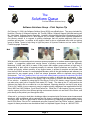
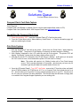
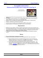
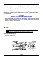
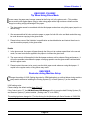
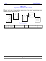
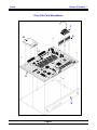
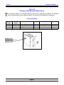
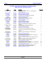
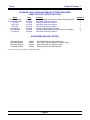
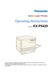
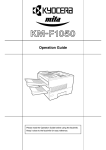
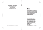
Copystar
Focus
June 2002
Volume 2 Number 1
W
elcome to the June 2002 Edition of the
Copystar Focus. It has been some time
since the release of the last Copystar Focus.
We have established a New Company Signature:
“One Company”.
As “One Company”, Kyocera Mita is focused on
Manufacturing State of the Art Laser Printers and
Digital Copiers, and providing a high level of
Technical Support and Software Solutions to our
Dealers and End Users. On the Technical side, the
Diagnostic Center is currently in the planning stage
for expansion. This expansion will provide Support
and Connectivity for future products and should be
completed by the end of the Year. The Solutions
Group provides second level support to the existing
Diagnostic Center concerning Software related
issues with our Printing Systems. In addition, the
Solutions Group supports our Regional Reps.,
System Support Engineers, Sales Engineers and
provides a level of Support to our Training Center.
MODEL
CONTENTS
PAGE
ALL
Common Prescribe Commands
ALL
The Solutions Queue (From the Software Solutions Group)
ALL
IB-2x NetBEUI Quick Install
ALL
Helpful Hints from the Diagnostic Center
ALL
Training Information on Dealernet
10
ALL
Tips from the Field
10
Ri 2530/3530/FS-9100/9500
New Bypass Lift Plate Spring
11
Ri 2530/3530/FS-9100/9500
Change to the Machine Packaging
11
Ri 2530/3530/FS-9100/9500
Unit Compatibility
Ri 4530/5530
Additional Information on Service Calls
Ri 4530/5530/6230
Hard Disk Drive Formatting
Ri 4530/5530
Change to the Drawer Heater Setup Procedure
15
Ri 4530/5530
Part List Corrections
16
DF-610/600
Part List Corrections
17
RC-4000d/5000d/Ri 4230/5230
Change to the Optional Drawer Heater Part Number
17
KM-C830D/8000C
Tip when using Gloss Mode
18
KM-C830D
Reminder During Setup
18
KM-C1530
Performance Change for Scanner Motor Drive
19
KM-C1530
Copier Stand Stabilizer Kit Available
20
Fiery X3e
Fiery X3e Parts Breakdown
CS-1810
Change to the Memory Board Ass’y
ALL
Technical Bulletins and Letters Released
2
3, 4, 5
6
7, 8, 9,
12, 13
14
14, 15
21, 22
23
24, 25
Focus
Volume 2 Number 1
Common Prescribe Commands
From DOS Mode
Below is a list of Prescribe Commands we have assembled for use in all current Digital
Copiers and Printers for adjusting parameters for specific Printer Environments.
Status Page: (All current Digital Copiers and Printers)
ECHO !R! STAT; EXIT; >LPT1 or PRN
Service Status Page: (All current Digital copiers and Printers)
ECHO !R! STAT1; EXIT; >LPT1 or PRN
(Print status page before all operations)
Event Log: (FS models)
ECHO !R! ELOG; EXIT; >LPT1 or PRN (ECOD = error codes)
Initialize Printer: (FS models)
ECHO !R! FRPO INIT; STAT1; EXIT; >LPT1 or PRN
Check margins (L parameters): (FS models)
ECHO !R! RES; MZP 0,0; BOX 30,30; PAGE; EXIT; >LPT1 or PRN
Changing Parameters: (All current digital copiers and printers)
ECHO !R! FRPO “parameter”, “value”; STAT1; EXIT; >LPT1 or PRN
CI-1100 Hard Drive Buffer size tweak for increased printer performance:
ECHO !R! FRPO I1, 1; FRPO H8, 50; FRPO M4, 5; FRPO M2, 3; FRPO S5, 2;
FRPO D6, 1; STAT1; RES; EXIT; >LPT1 or PRN (must have hard drive)
(It is recommended to increase memory before attempting this procedure)
When sending commands from our Utilities and Network Interface (ECHO) and (>LPT1 or PRN) are not
needed.
(Note: a space is needed after Echo and !R! and all semi colons and commas.)
Upgrade Firmware:
ECHO !R! UPGR “SYS”; EXIT; >LPT1 or PRN (SYSTEM)
COPY /b *****.*** PRN (Works for both System and Engine Firmware on
(File name)
FS-1800 and All current Digital copiers and Printers)
ECHO !R! BOOT “SPR”; EXIT; >LPT1 or PRN
COPY /b *****.*** PRN
(ENGINE)
Page 2
Focus
Volume 2 Number 1
The
Solutions Queue
From the Software Solutions Group
Software Solutions Group – Print Capture Tip
On February 21, 2001 the Software Solution Group (SSG) was officially born. The group includes Mr.
Nob Mori, Director of Software Solutions, Mr. Timothy O’Brien, Software Support Specialist and myself
Mr. John Helsel, Software Support Specialist. Located in Kyocera Mita America’s Headquarters in New
Jersey, SSG is responsible for 2nd level support for our Dealer, Reseller and Customer populations.
Our primary mission is to respond to printing challenges that will provide additional value to our
products and services. In addition to this support, there is also a coordinated effort with our training
group in Dallas, Texas to help bring to light the power of Kyocera Products and our native Printer
Control language, Prescribe.
Nob
Tim
John
With the world of connected products comes a different perspective to consider when supporting printer
installs. A competitive market and varying flavors of printing environments, such as Microsoft,
Macintosh, AS400, and UNIX (to name a few) require that support groups maintain a high level of
responsibility in their efforts to respond promptly to customer support questions and inquiries. The
number one priority, without question, in any support arena, is access to complete and accurate data
from the field. While access to a well-equipped laboratory with all the right hardware and software is a
great start for any support group, it does not always guarantee efforts to duplicate every printing
environment. This is the reason most of you may have started hearing requests for electronic print files
from the environment. Though it may not guarantee our ability to duplicate the environment, it does
give us the exact data being sent to our printer, and in the majority of cases, that data will be the basis
of our solution. In addition to using the KX Print Driver “Print to file” feature, newer Kyocera Printers
can also write a print job to Compact Flash cards (CF Cards). The data on the CF card can then be
delivered via floppy disk or e-mailed to us to be analyzed. Capturing data files via the KX print driver
“Print to file” feature is more commonly used to support printing challenges from applications like MS
Word, MS Excel, MS Publisher, Corel Word Perfect etc. While the CF card capture is more commonly
used to capture print files from different printing environments that do not use the KX Print Driver, and
print directly to the printer’s port through the driver.
All we ask is, you keep in mind that a challenge without a captured print file leaves several unanswered
questions, while a challenge with a captured print file shows us exactly what our printer needs to print.
This being said, we felt it a good idea to share the procedures for capturing print data files from using
the KX Print Driver “Print to File” method and using the Compact Flash Card “Write” method. Additional
support for these procedures can be obtained from our Helpdesk Support Group at 1-800-457-7951.
Page 3
Focus
Volume 2 Number 1
The
Solutions Queue
From the Software Solutions Group
Microsoft Windows Print Driver Data Capture:
From the application select “File à Print….” (See Fig. 1). This will display the “Print” dialogue screen from which
you can select “Print to file” (see fig. 2). Make sure that you have set all the features specific to your print job
such as cassette, duplex, staple, hole punch etc, so that all the related PDL commands can be captured. This
can be done from the “Properties” (see fig. 2) button in the “Print” dialogue screen.
Fig. 1
Fig. 2
After you have set all the print job features and selected the “Print to file” check box, click on the “OK” button (see
fig. 2). This will display the “Print to file” (see fig. 3) dialogue screen, from here you can select a folder to save the
file to and assign it an appropriate file name. This file can then be delivered via floppy disk or e-mailed to the
Copystar Support Specialist you are working with.
Fig. 3
Page 4
Focus
Volume 2 Number 1
The
Solutions Queue
From the Software Solutions Group
Compact Flash Card Data Capture
Tools Required:
Compact Flash Card Reader or Adapter (Device used to read compact flash cards in a PC)
Compact Flash Card (SanDisk 8M or 16M Compact Flash Card www.sandisk.com)
Formatting the Compact Flash Card
1. Power the machine “OFF” .Insert the Compact Flash (CF) Card into the printer.
2. From the Printer Menu select “Menu>Memory Card>Format”. A Format Information page will
print out confirming the format.
Print Data Capture
1. With the formatted CF card still in the printer. Select from the Printer Menu, “Menu>Memory
Card>Write Data”. The printer LCD will display “Processing” and then change to “Waiting”.
2. With “Waiting” displayed in the LCD, send the print job to the printer. The printer LCD will
display “Processing”, during which the data is being written to the CF.
3. After the file write to CF is complete, the LCD will return to “Waiting”. At this point you can press
the “GO” button to force a form feed and the printer LCD will return to “Ready”.
Note: The printer will remain in its “Waiting” mode until a Form Feed timeout
occurs. This is usually defaulted to 30 seconds – which means you have only 30
seconds to get the print data to the printer before it times out.
4. Once the LCD reads “Ready”, Turn “OFF” the Printer. remove the CF from the printer and install
into a PCMCIA adapter (for PCMCIA slot of PC) or a Compact Flash Card reader device for a
PC. This will allow you to read the CF as an external storage device of your PC. On the root of
the CF card you will see a file name DataS001. This file can either be delivered via floppy disk
or e-mailed to the Copystar Support Specialist you are working with.
Page 5
Focus
Volume 2 Number 1
IB-2x NetBEUI QUICK INSTALL
Referenced from the IB-2x Quick Configuration Guide Page 10
By Thomas Allen
Product Support Rep 2
•
•
•
•
•
•
Used for simple Peer to Peer printing for eight or less PCs (the standard recommended by
Microsoft).
Advantageous if the client has no TCP IP scheme being utilized, does not wish to assign a
static IP address or does not wish to use the KPRINT utility.
NetBeui Protocol is supported by Windows 95/98/ME, Windows NT 4.0, 2000 and XP.
NetBeui is enabled on a new IB-2x out of the box.
Limited to LAN use unless a Router that supports NetBeui is being used.
May take between 5-50 minutes for the IB-2x to show up on the network.
Requirements:
1. NetBeui must be enabled on the IB-2x network card through the Quick Set Up wizard from the
Kyocera Mita Network Library CD, the KM Net Viewer utility, from the keyboard of the machine or
via an internet browser web page. The Workgroup default: KY-NetPrinters and Printer Name
default: KYxxxxxx can be changed using the same methods.
2. The NetBeui Protocol must be enabled on all PCs by the Network Administrator (requires
reboot).
Set up:
1. Have the latest KX driver unzipped but not loaded.
2. There are two methods to find the print icon for the specific IB-2x card on the network.
a.) Browse the Entire Network under Network Neighborhood to locate the Workgroup
labeled KY-NetPrinters. Double click it, then right click the printer icon. Click Install
and follow the prompts in the Add Printer wizard to load the KX driver.
b.) Use the UNC name (Universal Naming Convention) from the Run command. Click
Start then Run from any Windows OS. Type two back slashes and the Printer Name.
Example: \\kyd0029e. Right click the printer icon. Click Install and follow the prompts
in the Add Printer wizard to load the KX driver.
Page 6
Focus
Volume 2 Number 1
Helpful Hints
From The Kyocera Mita Diagnostic Center
Now that the Print Systems for both Copiers and Printers have become more standardized, remembering specific
LPR port names has become much easier. The predecessors to these systems were a bit more varied. The
LPR Port is the Printer’s TCP IP address and Port Name that Windows 2000 and NT uses to direct the print job to
the correct printer. Without a valid IP address or Port Name, the Server or Workstation will Spool the job but
never make the connection to the printer.
WinNT Screen shots when LPR Port is created
Click “New Port”.
(Example) Type the Port Name exactly on shown Page 9.
Page 7
Focus
Volume 2 Number 1
Helpful Hints
From The Kyocera Mita Diagnostic Center
The example below shows how to select the Standard TCP/IP port option in Win 2000 & XP.
See Page 9 for list of Port Names
Page 8
Focus
Volume 2 Number 1
Helpful Hints
From The Kyocera Mita Diagnostic Center
The Table below refers to the Port Names for all Network Cards currently being used. Remember punctuation
counts. Upper case, lower case, spacing, underscores and dashes are part of certain Port Names. Type the Port
Name exactly as shown.
Windows 2000 & NT Port Names
Copiers/Printers
Network Card
Models
IB-2x
Ri 6230, Ri 4230/5230, Ri 4530/5530, CS1530/2030,
CS-1510/1810, FS-8000C and All FS Series
Printers.
Ci-1100, DP-2800 and Legacy Printers.
RC-4230/5230
RC-4000d/5000d
RC-3000d
Ecolan 3000E, 2000E, 1000E
NC-6
Printer I/F Board
NB-1
Notes
Port Name
9100
9100
lp
PRTGLNK
Lower case LP
No port name used.
Leave it blank.
No spaces
No spaces
NC-4A, NC-4B
NB-2
RC-2310/3010(L)
RC-2000d, RC-1800df, RC-1500df, RC1500d
Network Card
Fiery X3e
Models
KM-C1530
Port Name
print
Fiery X2e
Fiery ZX-2100/3300 Version
1.0 System Software
Fiery ZX-2100/3300 Version
1.1 System Software
Fiery Z4
Fiery X4
Fiery X2
Fiery XJ Series
Fiery
Ci-7600
Ci-7500
print_PRN-M
print_Copier-M
Notes
hold or direct can also
be used (*Note)
hold_PRN-M (*Note)
hold_Copier-M (*Note)
Ci-7600
print_PRN-M
hold_PRN-M (*Note)
Ci-7600
Ci-7600
Ci-7600
Ci-7500
Ci-1000
print
print
print_Copier-M
print_Copier-M
xjdirect
PORT1
PORT10001
Color Controllers
hold (*Note)
hold (*Note)
hold_Copier-M (*Note)
hold_Copier-M (*Note)
xjhold and xjprint can
also be used if the
optional Hard Drive is
installed. (*Note)
*HOLD queue – The print job is not processed unless released by the administrator or key operator using Fiery Utilities (Command
Workstation Web Services).
DIRECT – The print job is printed without spooling on the Fiery. Jobs are not saved in the Fiery Print Queue for reprints.
Page 9
Focus
Volume 2 Number 1
Training Information on DealerNet
Some dealers may not be aware that there is a wealth of information related to technical training posted
on DealerNet. Not only can you access the latest training schedule and enroll in classes on-line, you
will also find general information and FAQs, a list of prerequisites for training, a list of self-paced
training courses (video and CD-ROM), as well as detailed course descriptions for our "developmental"
training courses. Be sure to check out the PC and Network courses, Forms Creation / Prescribe
training, Printer / Scanner Utilities training, Ecosys Printer training, MICR Printer training and the
Advanced Digital Troubleshooting class. These "developmental" courses are great opportunities to
increase your technical department's skill level, productivity and efficiency.
At the DealerNet opening page, click on the Tech Training link at the top. Click on the appropriate
dealer category and explore the links!
Should you have any questions regarding technical training that are not covered on DealerNet, or if you
have any suggestions or comments related to training content on DealerNet or technical training in
general, please contact the National Training Center at 972-659-0055, by fax at 972-258-0924, or via
email to [email protected].
Tips from the Field
1. If you can't communicate with the Printer, take it off the Network, and try a crossover cable in order
to determine if the problem is in the Network or with the Machine.
2. Pagemaker 6.5: must have the Printer PPD file in the PPD4 subfolder on the PC. The driver has to
be in KPDL with “Data passthrough” turned on to see the PPD.
3. KX driver, click on Device Settings, locks up:
The cause is a conflict with the Video Card. If the latest Video Driver or available Patches don’t
help, use the 3D Patch to disable graphics.
4. The Transaction Report will not Print. The solution is to go into the fax parameter settings (KMF650 and KM-F1050 Instruction Handbook...pages 35-39 and set parameter 12 (COMM.
JOURNAL) to 2 for "always on".
Page 10
Focus
Volume 2 Number 1
Ri 2530/3530/FS-9100/9500
New Bypass Lift Plate Spring
M
ore than one sheet of paper may be fed from the Bypass Table due to the excessive spring
tension for the Bypass Lift Plate. This will occur only with special types of paper.
To prevent this problem, a New Bypass Spring is now available with a reduced tension.
Parts Information
Old Part
Number
34907380
New Part
Number
2BL07860
Description
Qty.
Interchangeability
Price
Bypass Spring
2/2
Y/Y
$.72
Ri 2530/3530
Change to the Machine Packaging
T
he packaging has been changed to prevent the machine from tipping over due to rough handling
during shipping. In addition, the cushioning material at the bottom of packaging has been changed
and the Skid has been reinforced to prevent the vertical conveying cover from becoming
damaged.
Ri 2530/AAH3013673 and above,
Ri 3530/AAJ3013028 and above,
FS-9500DN AAB3001646 and above
FS-9100DN AAA3004132 and above
•
•
•
The size of the inside packaging case has been increased to balance the center of gravity
of the machine.
The direction by which the claws of a folk-lift are inserted, has been changed by 90°.
The cushioning material on the bottom has been reinforced.
B
A
C
Page 11
FS-9100DN
FS-9500DN
Ri 2530
Ri 3530
A
743 → 768
743 → 768
B
884 → 887
996 → 996
C
804 → 911
804 → 911
Focus
Volume 2 Number 1
Ri 2530/3530/FS-9100/9500
Unit Compatibility
A
lthough the Ri 2530/3530 and FS-9100/9500 share the same engines and many internal
components, some Unit Assemblies are not compatible even though they may fit into the
machine. Various problems can occur from copy quality to error codes. The following tables
outline the compatibility and problems that can occur (See the following page).
Drum
Fixing
Transfer
Developer
Description
DK-700 Drum Unit
DK-701 Drum Unit
Drum Unit
FK-700 Fuser Unit
FK-701 Fuser Unit
Fuser Unit 120V
TR-700 Transfer
Ass'y
TR-701 Transfer
Ass'y
DV-700 Developer
Unit
Developer Unit
Ri 2530
Set, Kit MK-705
Ri 3530
Set, Kit MK-705
FS-9100DN
MK-700
FS-9500DN
MK-701
2BJ82020
For 120V
2BJ82020
For 120V
87800635
For 120V
87800636
For 120V
------2BJ93020
------2BJ93040
------2BJ93020
------2BJ93040
84395540
------2BK93010
-------
---84395545
------2BL93040
----
84395575
84395575
84395575
----
----
----
----
84396175
----
----
84395550
84395550
2BJ93010
2BJ93010
----
----
In addition, each Maintenance Kit now includes the following Replacement Parts.
Old Part
Number
----
New Part
Number
2AR07220
----
Description
Qty.
Interchangeability
Paper Feed Pulley
-/2
-/Y
2AR07230
Separation Pulley
-/3
-/Y
----
2AR07240
Leading Feed Pulley
-/3
-/Y
----
61706770
Upper Bypass Pulley
-/1
-/Y
----
2BL68290
Registration Cleaner Ass’y
-/1
-/Y
----
2BL16130
Front Registration Guide
-/2
-/Y
----
2BL07950
Upper Registration Cleaner
-/1
-/Y
Page 12
Focus
Volume 2 Number 1
Malfunctions that may occur when the Unit is not compatible with the model
Drum
Fixing
Transfer
Developer
P/N
84395540
84395545
2BJ93020
2BK93010
2BL93040
2BJ93040
84395575
84396175
84395550
2BJ93010
Description
DK-700 Drum Unit
DK-701 Drum Unit
Drum Unit
FK-700(U) Fuser Unit
FK-701(U) Fuser Unit
Fuser Unit 120V
TR-700 Transfer Ass'y
TR-701 Transfer Ass'y
DV-700 Developer Unit
Developer Ass’y
Ri 2530
1
1
C
5
5
C
C
10
11
C
Ri 3530
1
1
C
5
5
C
C
10
11
C
FS-9100DN
C
3
4
C
7
8
C
10
C
12
FS-9500DN
2
C
4
6
C
8
9
C
C
12
The "C" on the list indicates compatibility between the unit and the machine.
1. A Serviceman call "C7410" may illuminate, disabling the machine.
2. No error indication. Dark background may appear on the image.
3. No error indication. Lighter image may occur.
4. A message "Call Service 7410" + total Count, may illuminate and the machine will be disabled.
5. A Serviceman call "C6410" may illuminate and the machine will be disabled.
6. No error indication. Poor fixing may occur when printing continuously.
7. No error indication. Machine stabilization may take longer, Offset or Fixing failure may occur.
8. A message "Call Service 6410+ total Count may illuminate, disabling the machine.
9. No error indication. Separation failure or a paper crease may occur. The drum separation claw
may leave a stain on the paper.
10. No error indication. A slight black dot may be visible on the paper due to a pinhole on the drum.
11. A Serviceman call "C7400" may illuminate, disabling the machine.
12. A message "Call service 7400+ total Count may illuminate, disabling the machine.
Page 13
Focus
Volume 2 Number 1
Ri 4530/5530
Additional Information on Service Calls
T
he Initial Version Service Manual does not contain the information in the Table below. Please
update your Service Manual with this info or download Revision 1 from Dealernet.
Remark
Code
Contents
Cause of malfunction
C4100
Abnormal BD initialization (A)
C4110
* The Laser A output checking Main PCB failure
is performed when the Power
Source is turned ON and the
BD Signal cannot be detected.
Abnormal BD initialization (B) LSU failure (LD_B or BD PCB)
C5300
LSU failure (LD_A)
* The Laser B output checking Main PCB failure
is performed when the Power
Source is turned ON and the
BD Signal cannot be detected.
Eraser problem
The Connector for the Image
Formation Unit (cleaning lamp) is
* When the Drum Surface
disconnected.
Potential is checked after
Cleaning Lamp failure
completion of the potential
adjustment (auto adjustment), Engine Output PCB failure
the drum potential exceeds
400V.
Main PCB failure
Checking procedure /
Corrective measure
Replace LSU and check the
operation.
Replace the Main PCB and
check the operation.
Replace LSU and check the
operation.
Replace the Main PCB and
check the operation.
Check the Connector for the
Image Formation Unit
(Cleaning Lamp).
Replace the Cleaning Lamp
and check the operation.
Replace the Engine Output
PCB and check the operation.
Replace the Main PCB and
check the operation.
Ri 4530/5530/6230
Hard Disk Drive Formatting
F
ollow the procedure below if a formatting problem occurs and a service call message displays (Ri
4530/5530: C-0640, Ri 6230/C-038).
1. Run Simulation 906 to reset the service call code for partial operation control.
2. If the hard disk drive problem still exists after partial operation, "System error" will be indicated.
3. Enter service simulation mode with the "System Error" light ON (without turning the main switch
OFF) to execute Simulation 024 (HDD formatting).
Page 14
Focus
Volume 2 Number 1
When the hard disk drive problem (service call) message is on display, the hard disk drive is separated
from the operation and you can not format the HDD.
It is necessary to first reset the partial operation control using Simulation 906, then execute HDD
formatting with the "system error" light ON.
Detection of Hard Disk Drive problem (service call).
At the first detection, a "system error" will display instead of a service call.
If detected twice continuously, a service call will be displayed and partial operation for the hard disk
drive will be performed.
Ri 4530/5530
Change to the Drawer Heater Setup Procedure
F
ollow the Drum Heater Setup Procedure below during machine setup. This procedure is different
than the current procedure in the Service Manual. The Drawer Heater has been optional in the
past, but is standard for the Ri 4530/5530.
Before Change:
•
•
The Drawer Heater Relay Cable is included in the package at shipment.
The Drawer Heater and the Power Source PCB are to be connected with the provided Relay Cable at
setup.
After Change:
The Drawer Heater Relay Cable is already installed at the Factory.
However, it is connected only to the Drawer Heater side. The connector to the Power Source PCB is not
connected.
The Relay Cable must be connected to CN12 at the Power Source PCB during the setup.
Drawer Heater Connection Procedure
1. Remove the Lower Rear Cover.
2. Connect the Drawer Heater Relay Cable Connector to CN12 at the Power Source PCB.
3. Reinstall the Lower Rear Cover.
Page 15
Focus
Volume 2 Number 1
Ri 4530/5530
Parts List Corrections
T
he following Parts in the Ri 4530/5530 Parts List were incorrectly listed in Fig. 16 CONVEYING
SECTION I. Please make the corrections as shown below in your Parts List.
Parts Information
Number
Incorrect
Part Number
Incorrect
Description
Correct
Part Number
Correct
Description
Qty
23
2BC27780
Fan Fixing
2BC27790
Fan Cooling
1
T
he following Parts in the Ri 4530/5530 Parts List were incorrectly listed in Fig. 40 ELECTRICAL
SECTION II. Please make the corrections as shown below in your Parts List.
Parts Information
Old
Number
Incorrect
Part Number
Incorrect
Description
New
Number
Correct
Part Number
Correct
Description
41
2BC27790
Fan Cooling
1
2BC27780
Fan Fixing
1
2BC27780
Fan Fixing
41
2BC27950
Fan HDD
Page 16
Focus
Volume 2 Number 1
DF-610/600
Parts List Corrections
T
he following Parts in the DF-610/600 Parts List were incorrectly listed in Fig. 4 PAPER FEED-IN
SECTION. Please make the corrections as shown below in your Parts List.
Parts Information
Old
Number
Incorrect
Part Number
Incorrect
Description
New
Number
Correct
Part Number
Correct
Description
13
3B816210
Roller, Sub
Conveying
69
3B822220
Pulley 31, Tray
Feed- in
RC-4000d/5000d/RC-4230/5230
Change to the Optional Drawer Heater Part Number
T
he Optional Drawer Heater consists of five items that have now been combined into one Item
number. Please make the corrections as shown below in your Service Manual.
Parts Information
Old Part
Number
----
New Part
Number
8402AC10
Description
Qty.
Interchangeability
Price
Set Drawer Heater 120V
-/1
-/Y
$32.78
•34860030
----
Heater Cassette
-/1
-/Y
N/A
•68427020
----
Power Source Switch
-/1
-/Y
N/A
•2AC60020
----
Dehumidifier Relay Cable
-/1
-/Y
N/A
•B1304060
----
M4X6 Tight Screws
-/1
-/Y
N/A
•M2107120
----
Binding Band SG-130
-/1
-/Y
N/A
Page 17
Focus
Volume 2 Number 1
KM-C830/D, FS-8000C
Tip When Using Gloss Mode
I
•
n rare cases, the paper may become creased at the fixing unit in the gloss mode. (This problem
occurs mainly with regular paper (64g) or when using paper with a high moisture content and the
image is covering a high percentage of the paper.
The gloss mode cannot be combined with the thick paper mode when using thick paper (equal to or
above 100g).
1. We recommend that full-color exclusive paper or paper for both full-color and black and white copy
be used whenever copying in the gloss mode.
2. Please inform users of the limitation in specification as described below and instruct them how to
use the machine properly in the gloss mode.
Details
1. In the gloss mode, the paper will pass through the fixing unit at a slower speed than in the normal
mode, so more heat can be applied to the paper to increase the gloss level.
2. The same control will be applied in the thick paper mode as well to enhance fixing performance. It
will not be possible to decrease the paper conveying speed to use the gloss mode combined with
the thick paper mode.
3. Please instruct the users to be sure to use the thick paper mode whenever using thick paper. If
copied in the regular mode, a fixing failure may result.
KM-C830/D
Reminder during Machine Setup
C
hange the setting of U265 (Setting the code for OEM destination) as outlined below during machine
setup and/or whenever installing the Printing System (P) or Scan System (C) on the machine.
U265 setting value:
Please change the default setting from "0" to "2".
If the Code is set to "0", the KM-NetViewer/JOB-Manager will not recognize both Printing System (P)
and Scanner System (C) when installed. (Setting code "0" is for OEM.)
The setting has been changed to "2" at the factory for the Machines with Serial Number of S3000798
and above. Please check the serial number and change the setting if necessary.
Page 18
Focus
Volume 2 Number 1
KM-C1530
Performance Change for Scanner Motor Drive
T
he width of the Timing Belt has been increased from 4 mm to 6 mm to improve Scanner Motor
drive. As a result, the shape of the Motor and the Mount will be modified. Please be aware that
there will be no parts compatibility between the old and the new parts after this change. The
change has been implemented at the Factory from Serial # 3000211 and above.
Scanner Motor
Timing Belt (Increased from 4 ~ 6mm)
The Pulley has been
increased from 6mm ~ 7mm
20 ~ 21mm
Old
New
Parts Information
Old Part
Number
5F920250
New Part
Number
5F920251
Description
Qty.
Interchangeability
Price
Timing Belt
1/1
X/X
$13.38
5F930960
5F930961
Motor
1/1
X/X
$131.83
5F920480
Bracket
-/1
-/X
$16.11
----
Page 19
Focus
Volume 2 Number 1
KM-C1530
Copier Stand Stabilizer Kit Available
I
t is recommend that the Scanner and the Printer be secured to the Copier Stand using screws whenever set-up
with the Stand. If they are installed separately, please be sure to install the new Stabilizer Kit to the Copier
Stand to prevent the Stand from tipping over.
Parts Information
Old Part
Number
----
New Part
Number
5F920400
Description
Qty.
Interchangeability
Price
Stabilizer Kit
-/1
-/Y
$355.82
Page 20
Focus
Volume 2 Number 1
Fiery X3e Parts Breakdown
C
A
B
E
D
Page 21
Focus
Volume 2 Number 1
Fiery X3e for KM-C1530 Price List
84318628
EFI P/N
45018628
Fiery X3e
84318632
45018632
Fiery X3e
Fiery X3e
Fiery X3e
84318633
84318634
84318635
45018633
45018634
45018635
Fiery
Options
X3e
Fiery X3e
84321000
45021000
84321328
45021327
Fiery X3e
84322801
45022801
84302101
KMA P/N
Fiery
X3e
Fiery
X3e
Ship
Groups
Description
SHIP
GP,X3E,CF2001/1501,128MB,US/DOMES
TIC
SHIP
GP,X3E,CF2001/1501,192MB,JAPAN
SHIP GP,X3E,CF2001/1501,128MB,INTL
SHIP GP,X3E,20C-M,128MB,US
SHIP GP,X3E,20C-M,128MB,INTL
KIT,MEMORY UPGRADE,X3E,256MB,
DIMM
KIT,MEMORY UPGRADE,X3E,128MB
DIMM
KIT,CMND WKSTN,JPN,FIERY X3E
Dealer Price
$2,362.49
$3,100.51
$2,362.49
$2,362.49
$2,362.49
$1,159.49
$583.49
$298.51
A
B
C
84318813
84318818
84318842
D
E
84318869
84318872
45002101 KIT,SPARE,CBL,PARALLEL,X2E/X3E,PR
N-M
45018813
KIT,SPARE,128MB,DIMM
45018818 KIT,SPARE,HDD,6.0GB,TOSHIBA 2.5 IN
45018842
KIT,SPARE,FAN WITH
HEATSINK,5V,CPU,PUSH-PIN
45018869
KIT,SPARE,PANEL,MTHRBD
45018872
KIT,SPARE,PCBA
Fiery
Media
X3e
Fiery X3e
Fiery X3e
Fiery X3e
Fiery X3e
Fiery X3e
Fiery X3e
Fiery X3e
Fiery X3e
84322458
45019222
MEDIA PACK,V1.0,ENGLISH,X3E
$137.70
84319224
84319225
84319226
84319228
84319230
84319245
84309353
84319354
45019224
45019225
45019226
45019228
45019230
45019245
45019353
45019354
MEDIA PACK,V1.0,FRENCH,X3E
MEDIA PACK,V1.0,ITALIAN,X3E
MEDIA PACK,V1.0,GERMAN,X3E
MEDIA PACK,V1.0,SPANISH,X3E
MEDIA PACK,V1.0,JPN,X3E
MEDIA PACK,V1.0,ENGLISH
KIT,SVCE,V1.0,ENGLISH,X3E
KIT,SVCE,V1.0,JPN,X3E,CF2001-1501
$74.99
$74.99
$74.99
$74.99
$74.99
$74.99
$37.51
$37.51
Spares
Page 22
$37.51
$576.00
$375.01
$74.99
$60.01
$1,575.01
Focus
Volume 2 Number 1
CS-1810
Change to the Memory Board Ass’y
T
he replaceable DIMM on the Standard Memory Board will be replaced with SDRAM. The SDRAM
will be soldered directly onto the Memory Board. The Socket for the DIMM will be eliminated.
Parts Information
Old Part
Number
2A201010
New Part
Number
2A182030
Description
Qty.
Interchangeability
Price
MB-6 (16MB)
1/1
Y/Y
N/A
2A228010
2A228011
Memory PCB
1/1
Y/Y
$472.01
IC DIMM
1/-
N/-
N/A
2A228020
----
MEMORY PCB
Socket is eliminated, and
SDRAM is soldered on
MEMORY PCB.
Page 23
Focus
Volume 2 Number 1
TECHNICAL BULLETINS AND DEALER LETTERS RELEASED
SINCE THE LAST COPYSTAR FOCUS
Model
RC-4000d/5000d
RC-4000d/5000d
Date
02/24/00
04/28/00
RC-2310L/3010L
Ri 4230/5230
FS-1200
FS-1750/3750
Ri 6230
F-4130/4330
RC-4000d/5000d
FS-1800/N, 3800/N
FS-1750/3750
CS-1530/2030
LDC-820
FS-1000+
F-4130/4330
06/19/00
07/12/00
07/19/00
08/21/00
10/10/00
09/28/00
11/17/00
11/30/00
01/11/01
01/26/01
02/28/01
03/02/01
03/07/01
FS-1800/N, 3800/N
Ri 6230
KM-C1530
Ri 4230/5230/
RC-4000d/5000d
CS-1530/2030
03/27/01
04/18/01
05/18/01
05/23/01
Ri 4230/5230/
RC-4000d/5000d
FS-8000C
Ri 6230
General
Ri 2530/3530
RC-6230
07/19/01
07/24/01
08/01/01
08/15/01
09/19/01
10/10/01
CS-1530/2030
RC-2310L/3010L
KM-C830/D
General
General
General
Ri 4530/5530
Ri 4530/5530
KM-C830D
FS-1010
10/22/01
10/30/01
11/01/01
01/09/02
02/13/02
04/26/02
02/05/02
04/24/02
03/06/02
01/04/02
05/08/01
Contents
Introduction to ES-2
Software Ver. 1.11 & Firmware Ver. 1.08 Upgrade for
Printing System (G)
New Model Product Information
New Model Product Information
New Model Product Information
Conversion of DP-1400/1800 to FS-1750/3750
New Model Product Information
Measure to Prevent Jams
Improving the Performance of the SRDF-1
New Model Product Information
Auto Tray Switching
New Model Product Information
Measure for Original Feed Jam
New Model Product Information
Measures to Further Improve the Efficiency of Paper
Transport
Clarifying Waste Toner Bottle Replacement
Performance Enhancement Kit
New Model Product Information
Change to the Lower Registration Guide Ass’y
Bulletin #
7
8
Firmware Update to Enable Scanning and Enhanced
Finishing
Measure to Prevent Shifting of the Lift Plate (ST-8)
2
New Model Product Information
Measure for LCD Display Failure
Kyocera Mita Digital Library CD-ROM Ver. 6.0 (KX Driver)
New Model Product Information
Measure to Prevent Damage to the Large Deck Lift Motor
Gear
Manufacturing Enhancement (Addition of Flywheel)
Measure for Bypass Leaf Spring Damage
New Model Product Information
Kyocera Mita Digital Library CD-ROM Ver. 6.3.1 (KX Driver)
Unpublished End User Error Codes
Kyocera Mita Digital Library CD-ROM Ver. 6.5.1 (KX Driver)
New Model Product Information
Countermeasure for DF-610/600 Main Board Failure
Measure for Middle Transfer Cleaning Failure
New Model Product Information
Page 24
1
1
1
1
1
1
9
1
2
1
2
1
2
2
2
1
2
3
1
3
37
1
4
3
2
1
38
39
40
1
2
2
1
Focus
Volume 2 Number 1
TECHNICAL BULLETINS AND DEALER LETTERS RELEASED
SINCE THE LAST COPYSTAR FOCUS
Model
FS-1800/N, 3800/N
FS-9100DN/9500DN
FS-1900
KM-F1050
KM-F650
CS-1510/1810
CS-1530/2030
FS-1800+/N
Date
10/25/01
09/28/01
01/23/02
01/19/02
02/27/02
02/12/02
02/12/02
05/02/02
Contents
Firmware Update to Control Fan Noise During Sleep Mode
New Model Product Information
New Model Product Information
New Model Product Information
New Model Product Information
Outline of Unpublished Jam Codes
Precaution when Updating Printing System (K) Firmware
New Model Product Information
AUTHORIZED DEALER LETTERS
RC-5000d Dealers
KM-C1530 Dealers
KM-C1530 Dealers
FS-8000C Dealers
4/28/00
6/08/01
9/18/01
10/29/01
Ri 4230/5230 Service and Part Manuals
KM-C1530 Technical Bulletin #1 Updated Page 2
KM-C1530 Waste Toner Bottle Update
KM-C830 Service and Parts Manuals
* All Information and Pricing Subject to Change without Notice.
Page 25
Bulletin #
3
1
1
1
1
2
4
1