1
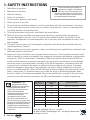
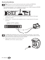
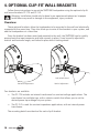
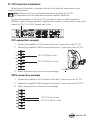
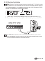
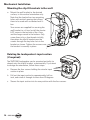
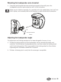
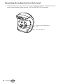
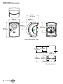
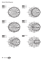
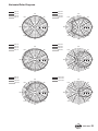
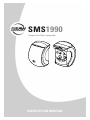
SMS1990
Compact Two-Way Loudspeaker
INSTRUCTION MANUAL
1. SAFETY INSTRUCTIONS
The exclamation point within an
1.
2.
3.
4.
5.
6.
7.
8.
Read these instructions.
equilateral triangle is intended to
alert the user of the presence of
Keep these instructions.
important operating and maintenance
Heed all warnings.
(servicing) instructions in the literature
accompanying the apparatus.
Follow all instructions.
Do not use this apparatus near water.
Clean only with a dry cloth.
Do not block any ventilation openings. Install in accordance with the manufacturer’s instructions.
Do not install near any heat sources such as radiators, heat registers, stoves, or other apparatus
(including amplifiers) that produce heat.
9. Only use attachments/accessories specified by the manufacturer.
10. Refer all servicing to qualified service personnel. Servicing is required when the apparatus
has been damaged in any way, such as liquid has been spilled or objects have fallen into the
apparatus, the apparatus has been exposed to rain or moisture, does not operate normally, or has
been dropped.
11. The entire sound system must be designed in compliance with the current standards and laws
regarding electrical systems.
12. When installing and using this apparatus, keep in mind the technical specifications indicated in the
dedicated section of the manual.
13. Exposure to high sound levels can cause permanent hearing loss. The sound pressure level which
leads to hearing loss varies considerably from one person to another, and depends on the duration
of exposure. The U.S. Government’s Occupational Safety and Health Administration (OSHA) has
established the maximum sound pressure levels that can be with stood without causing damage,
which are shown in the table below. According to the OSHA regulations, any exposure over the
maximum limits indicated in the table can reduce the hearing capacity of a person. To prevent
potentially dangerous exposure to high sound pressure levels, anyone subjected to such levels
must use suitable protection. When a EAW Commercial product capable of producing high sound
levels is being used, it is therefore necessary to wear ear plugs or protective earphones when
the limits shown in the table are exceeded. Consult the specifications provided in the instruction
manual to know the maximum sound pressure (SPL) the loudspeaker is capable of producing.
WARNING! This
equipment has been
designed to be installed
by qualified professionals
only! There are many factors
to be considered when
installing professional sound
reinforcement systems,
including mechanical and
electrical considerations, as
well as acoustic coverage and
performance. EAW Commercial
strongly recommends that this
equipment be installed only by
a professional sound installer or
contractor.
– SMS1990
Duration per
day (hours)
Sound level
(dBA)
Typical example
8
90
Duo in a small club
6
92
4
95
3
97
2
100
1.5
102
1
105
0.5
110
0.25 or less
11 5
Subway train
Very loud classical music
Locomotive at 50 feet
Loudest parts at a rock concert
Part No. 0018444 Rev. A 11/2007
© 2007 LOUD Technologies Inc. All Rights Reserved.
Printed in China.
14. Rigging Precautions: When mounting or suspending EAW Commercial loudspeaker
enclosures, it is essential that load ratings, rigging techniques, and special safety
considerations be appropriate for the installation. Use only the mounting/rigging points
on the loudspeaker enclosure intended for this purpose. The user must determine the load
requirements, dynamic loading, and any other contributing factors affecting the loudspeaker
installation. The user must determine the proper design factor for specific applications and
the required load rating of the connection to structure. Comply with all applicable federal,
state, and local regulations.
EAW Commercial strongly recommends the following rigging system practices:
• Documentation: Thoroughly document the mounting/rigging design with detailed
drawings and parts lists.
• Analysis: Have a licensed structural engineer or other qualified professional review and
approve the mounting/rigging design before its implementation.
• Installation: Use personnel experienced and qualified for mounting/rigging loudspeakers
in accordance with and in compliance with all federal, state and local regulations.
DANGER: Loudspeakers should be mounted or suspended only by persons with knowledge
of the proper hardware and rigging techniques. Failure to follow these precautions may
result in damage to the equipment, personal injury, or death.
TABLE OF CONTENTS
1. SAFETY INSTRUCTIONS......................................................... 2
2. INTRODUCTION........................................................................ 4
3. INSTALLATION......................................................................... 5
4. OPTIONAL CLIP-FIT WALL BRACKETS................................. 10
5. SPECIFICATIONS .................................................................... 17
SMS1990 Dimensions........................................................ 18
Performance Graphs.......................................................... 19
6. SERVICE INFORMATION......................................................... 22
7. EAW COMMERCIAL WARRANTY.......................................... 23
SMS1990– 2. INTRODUCTION
Congratulations on the purchase of your new EAW Commercial loudspeaker. You now
own one of the finest professional audio products available – the result of exceptional
engineering and meticulous craftsmanship. Please read these instructions to get the
maximum performance from your new loudspeaker.
Each EAW Commercial loudspeaker is intended for professional use. The construction,
components, and hardware have been designed to provide robust, reliable performance for
its intended application. Please ensure that you fully understand its proper installation and
operation before use.
This manual describes the SMS1990 loudspeaker and the optional clip-fit mounting
system. The SMS1990 is an economical solution for exceptional fidelity in speech
reinforcement and background music applications. It is especially suited for small to midsized spaces with excessive reverberation or problematic sound reflections. The drivers
and system voicing are designed to maximize vocal range clarity and speech intelligibility,
without compromising the broadband frequency response required for pleasing music
reproduction.
The included bracket allows setting the enclosure’s vertical angle for wall-mounting.
Two optional mounting brackets are available that allow the loudspeaker to be mounted
to the wall and electrically connected at the same time. These “clip-fit” brackets allow the
SMS1990 to be easily clipped in place and adjusted within a wide range of angles. One
bracket (CF-1TX) includes an internal transformer for constant voltage applications, and the
other (CF-1LZ) is for constant impedance applications.
Features:
• 90 degree horizontal x 90 degree
vertical nominal beamwidth
• Passive crossover for
economical, single-amplifier
operation
• Includes adjustable mounting
bracket
• Optional clip-fit bracket for
constant-voltage systems
• Optional clip-fit bracket for
constant-impedance systems
• Five-year warranty
– SMS1990
Applications include:
•
•
•
•
•
•
Houses of Worship
Transportation Terminals
Museums
Theme Parks
Schools
Meeting Rooms
3. INSTALLATION
Unpacking and Inspection
Visually inspect the outside of the shipping carton and check for any damage. After
unpacking, if you find concealed damage to the loudspeaker, save the packing materials for
the carrier’s inspection, notify the carrier immediately, and file a shipping damage claim.
Although EAW Commercial will help in any way possible, it is always the responsibility of
the receiving party to file any shipping damage claim. The carrier will help prepare and file
this claim.
Mounting Precautions
The mounting bracket provided can be used for wall mounting the loudspeaker.
WARNING: Installation should only be done by an experienced technician.
Improper installation may result in damage to the equipment, injury or death. Make
sure that the loudspeaker is installed in a stable and secure way in order to avoid any
conditions that may be dangerous for persons or structures:
• Check to make sure that the support surface (e.g., wall, etc.) has the necessary
mechanical characteristics to support the weight of the loudspeaker without the
danger of it falling.
• Always use support elements suitable for the material of the wall that will support
the loudspeaker (e.g., screw anchors for bricks, screw anchors for cement, etc.). Due
to various construction methods and materials used today, the hardware for securing
the bracket to the mounting surface is not supplied. Consult a building professional
for the proper mounting hardware before mounting the bracket.
• Before mounting the loudspeaker, carefully check all the components to be used to
make sure there is no damage, deformation, corrosion and/or missing or damaged
parts that could reduce the safety of the installation.
• Consult a professional rigger or structural engineer prior to mounting loudspeakers
from a structure not intended for that use. Always know the working load limit of the
structure supporting the loudspeaker. Always make sure that the rigging hardware
minimum rating is at least five times the actual load.
• Avoid installing the loudspeaker in places exposed to harsh weather conditions.
SMS1990– Wall bracket mounting instructions
Follow these instructions to mount the SMS1990 loudspeaker using the supplied wall
mount bracket.
Warning: Installation should only be done by an experienced technician. Improper
installation may result in damage to the equipment, injury or death.
1. Mounting the wall bracket to the wall:
[4.88]
a. Mount the bracket so the slots in the ends are upwards as shown. This124.0
will support
the SMS1990 even if the clamp nuts become loose.
A
B
B
B
A
B
B
A
B
Horizontal mounting
When mounted on a wall, the bracket
should be centered over a J-box that is
2X 4.00
appropriately rated and installed
the
124.0 for
[4.88
]
weight of the speaker and bracket. The
provided 6-32 screws should be inserted
through the holes labeled “A” as shown.
The holes110.0
labeled “B” should be used to 2X 4.00
]
attach the[4.33
bracket
to a wall stud with usersupplied hardware.
B
110.0
b. The wall bracket can also be mounted sideways on
a vertical wall, or mounted on a
[4.33]
ceiling.
Again,
make sure that you consult a rigging
professional to examine the wall
B
A
or ceiling and determine the proper hardware for mounting the bracket.
15.00 [
4X
15.00 [0.
Ceiling mounting
A
B
Sideways mounting
B
B
B
– SMS1990
A
110
[4.3
2. Mounting the SMS1990 loudspeaker to the wall bracket:
Wall bracket
Side bracket
Plain washer
Lock washer
Rubber washer
M5 Acorn nut
a. On each side of the SMS1990, undo two screws as shown.
Remove the small trim pieces and keep them safe.
b. Use the same screws, and the lock washers provided in the
accessories box, to attach a side bracket to each side of the
SMS1990.
c. Fit a large rubber washer on each side bracket
and fit this assembly onto the wall bracket. Add
the plain washer, lock washer, and acorn nut and
hand-tighten.
d. Adjust the loudspeaker to the desired angle, and
secure the acorn nuts. These are M5 size.
SMS1990– Electrical Installation
Note: Observe all local and national codes when installing the SMS1990.
All connections must be made with the power amplifier turned off.
The following example of a low-impedance connection uses a EAW Commercial CAZ800
amplifier. This amplifier uses a screw-terminal output.
PUSH
B (+)
B (--)
INPUT
B
OFF
LINE
INPUT
CONNECTION
CAZ800-AMPLIFIER
CAUTION
TO REDUCE THE RISK OF FIRE OR ELECTRIC SHOCK,
DO NOT EXPOSE THIS APPARATUS TO RAIN OR
MOISTURE. SEE INSTRUCTIONS BEFORE USING.
BREAKER
SERIAL /DATE CODE
ON
SUBSONIC
FILTER AT 30Hz
(BALANCED)
GND
AMP MODE
PUSH
A (--)
INPUT
A
MONO
STEREO
CHANNEL B BRIDGED CHANNEL A
B (+) B (-) (+)
MANUFACTURED IN CHINA
2004 LOUD TECHNOLOGIES INC.
"EAW" IS A REGISTERED TRADEMARK
OF LOUD TECHNOLOGIES INC.
(-) A (+) A (-)
BRIDGE
A (+)
OFF
ON
CLIP LIMIT
LINE
(BALANCED)
CAUTION
TO REDUCE THE RISK OF FIRE OR ELECTRIC SHOCK,
DO NOT EXPOSE THIS APPARATUS TO RAIN OR
MOISTURE. SEE INSTRUCTIONS BEFORE USING.
1. Connect the A + terminal on the amplifier to the (+) screw terminal of the input
CAZ800-AMPLIFIER
connector as shown.
BREAKER
SERIAL /DATE CODE
2. Connect the A – terminal on the amplifier to the (–) screw terminal of the input
connector.
CHANNEL B BRIDGED CHANNEL A
B (+) B (-) (+)
(-) A (+) A (-)
MANUFACTURED IN CHINA
2004 LOUD TECHNOLOGIES INC.
"EAW" IS A REGISTERED TRADEMARK
OF LOUD TECHNOLOGIES INC.
The SMS1990 loudspeakers have a nominal impedance of 8 ohms. If you connect
other loudspeakers in parallel, make sure that the overall impedance does not drop
below the minimum required by your power amplifier.
3. Plug the input connector into the back of the
SMS1990, until it clicks securely in place.
– SMS1990
4. Disconnecting the input connector:
a. Slide the red plastic tab towards the center of the loudspeaker, and hold while you
press the red center button inwards. The input connector can then be removed.
1. Slide this spring-loaded tab to
the left.
2. Press this button in.
3. Pull out the connector.
SMS1990– 4. OPTIONAL CLIP-FIT WALL BRACKETS
Follow these instructions to mount the SMS1990 loudspeaker using the optional clip-fit
wall mount brackets CF-1TX and CF-1LZ.
Warning: Installation should only be done by an experienced technician. Improper
installation may result in damage to the equipment, injury or death.
Overview
These optional brackets allow the loudspeaker to be mounted to the wall and electrically
connected at the same time. They also allow you to wire all the brackets in your system, and
add the loudspeakers at a later time.
Once the bracket has been wired and mounted to the wall, the SMS1990 can be quickly
pressed onto the input connector and held securely in place. It can be easily adjusted in
vertical and horizontal angle, and locked in place with a locking wheel.
Lock/unlock wheel
Horizontal adjustment
Vertical adjustment
Two brackets are available:
• The CF-1TX includes an internal transformer for constant voltage applications. The
transformer has multiple taps, with a selector switch that allows you to set the
desired power tap wattage for your system.
• The CF-1LZ is used for constant impedance applications, with no internal power
transformer.
The mounting details are identical for each clip-fit bracket.
10 – SMS1990
CF-1TX Electrical Installation
Before the clip-fit bracket is mounted to the wall, the electrical connections to your
system should be made.
Note: Observe all local and national codes when installing the CF-1TX. All connections must be made with the power amplifier turned off.
The following examples of 70 V and 100 V connections show an EAW Commercial
CAM160, a typical mixer/amplifier. Its speaker-level output is a screw terminal strip, with
outputs for 25 V, 70 V, 100 V, ground, and 4 ohm.
70 V connection example
1. Connect the amplifier’s 70 V terminal to the red (+) input wire on the CF-1TX.
2. Connect the amplifier’s GND terminal to the black (–) input wire on the CF-1TX.
To CF-1TX red (+) wire
To CF-1TX black (–) wire
3. Select the power tap as shown on the next page.
100 V connection example
1. Connect the amplifier’s 100 V terminal to the red (+) input wire on the CF-1TX.
2. Connect the amplifier’s GND terminal to the black (–) input wire on the CF-1TX.
3. Select the power tap as shown on the next page.
To CF-1TX red (+) wire
To CF-1TX black (–) wire
SMS1990– 11
Selecting the power tap (CF-1TX only):
Make sure the power amplifier is turned off when adjusting the power taps or making
connections.
1. Select the desired power tap by turning the switch with a
flat-ended screwdriver.
If you are using a 70 V system, the wattage ratings are: 4, 8,
16, and 32 W.
If you are using a 100 V system, the available wattage
ratings are: 8, 16, and 32 W.
Make sure that you do not overload the amplifier. This may
cause overheating to the amplifier, and possible damage to
your loudspeakers. To avoid overloading, make sure that the
selected taps on the loudspeakers add up to no more than
80% of the rated power of the amplifier being used.
12 – SMS1990
CF-1LZ Electrical Installation
Note: Observe all local and national codes when installing the CF-1LZ clip-fit bracket.
All connections to the loudspeaker must be made with the power amplifier turned off.
The following example of a low-impedance connection uses a EAW Commercial CAZ800
amplifier. This amplifier uses a screw-terminal output.
PUSH
B (+)
B (--)
INPUT
B
OFF
LINE
INPUT
CONNECTION
CAZ800-AMPLIFIER
CAUTION
TO REDUCE THE RISK OF FIRE OR ELECTRIC SHOCK,
DO NOT EXPOSE THIS APPARATUS TO RAIN OR
MOISTURE. SEE INSTRUCTIONS BEFORE USING.
BREAKER
SERIAL /DATE CODE
ON
SUBSONIC
FILTER AT 30Hz
(BALANCED)
GND
AMP MODE
PUSH
A (--)
INPUT
A
MONO
STEREO
CHANNEL B BRIDGED CHANNEL A
B (+) B (-) (+)
MANUFACTURED IN CHINA
2004 LOUD TECHNOLOGIES INC.
"EAW" IS A REGISTERED TRADEMARK
OF LOUD TECHNOLOGIES INC.
(-) A (+) A (-)
BRIDGE
A (+)
OFF
ON
CLIP LIMIT
LINE
(BALANCED)
CAUTION
TO REDUCE THE RISK OF FIRE OR ELECTRIC SHOCK,
DO NOT EXPOSE THIS APPARATUS TO RAIN OR
MOISTURE. SEE INSTRUCTIONS BEFORE USING.
1. Connect the A + terminal on the amplifier to the red (+) input wire on the CF-1LZ.
CAZ800-AMPLIFIER
BREAKER
SERIAL /DATE CODE
2. Connect the A – terminal on the amplifier to the black (–) input wire on the CF-1LZ.
CHANNEL B BRIDGED CHANNEL A
B (+) B (-) (+)
(-) A (+) A (-)
MANUFACTURED IN CHINA
2004 LOUD TECHNOLOGIES I
"EAW" IS A REGISTERED TRADE
OF LOUD TECHNOLOGIES IN
The SMS1990 loudspeakers have a nominal impedance of 8 ohm. If you connect
other loudspeakers in parallel, make sure that the overall impedance does not drop
below the minimum required by your power amplifier.
SMS1990– 13
Mechanical Installation
Mounting the clip-fit brackets to the wall:
a. Mount the wall bracket to the desired
surface, in this vertical orientation only.
Note that the bracket has two mounting
holes with vertical spacing that allows
them to be used with a standard wall Jbox.
Two screws are supplied for securing the
wall bracket to a J-box. Install the shorter
6-32 screw in the top hole of the J-box,
and the longer screw in the bottom. Only
screw them in by a few threads initially,
then place the clip-fit bracket over the
screws through the key-hole slots in the
bracket as shown. Tighten the screws once
the bracket is securely in place.
Rotating the loudspeaker’s input section
(if required):
The SMS1990 loudspeaker can be mounted vertically (as
shown) onto the clip-fit bracket, or horizontally. If you want
to change the orientation, follow these steps:
a.Remove the four screws holding the circular input
section in place.
b. Pull out the input section by approximately half an
inch, and rotate it through no more than 90 degrees.
c. Secure the input section into its new position with the four screws.
14 – SMS1990
Mounting the loudspeaker onto a bracket:
a. Once the clip-fit bracket has been wired and secured to the wall, press the
loudspeaker onto the input connector, until it clicks into place.
Make sure it is fitted on correctly. It is possible to fit it on upside-down, but it will not
click in place, or be securely held on the bracket, or make an electrical connection.
Lock
Lock/unlock wheel
Unlock
Adjusting the loudspeaker angle:
The adjustment and locking mechanism has been designed to be easy to use.
a. Rotate the locking wheel until the loudspeaker can be rotated horizontally and
vertically. Find the desired loudspeaker position, and then rotate the locking wheel
until it locks this position. Slots are provided in the locking wheel to allow further
tightening with a flathead screwdriver if required.
b. Perform a listening test to verify that the coverage is acceptable.
SMS1990– 15
Unmounting the loudspeaker from the bracket:
a. Slide the red plastic tab towards the center of the loudspeaker, and hold while you
press the red center button inwards. Pull the SMS1990 off the bracket.
1. Slide this spring-loaded tab to
the left.
2. Press this button in.
16 – SMS1990
5. SPECIFICATIONS
Model
Woofer
Woofer Loading
Tweeter
Tweeter Loading
SMS1990
3 in x 2 cone
Vented
1 in x 1 dome
Waveguide
Operating Range (–10 dB)
99 Hz - 20 kHz
Horizontal Beamwidth - Nominal
90 degrees
Vertical Beamwidth - Nominal
90 degrees
Axial Sensitivity (whole space SPL)
86 dB, 99 Hz - 20 kHz
Input Impedance - Nominal
8 ohm
Input Impedance - Minimum
6.7 ohm @ 390 Hz
Recommended High Pass Filter
≥ 90 Hz, 24 dB/octave
Butterworth
Power Handling
75 W, 25 V @ 8 ohm
Power taps 70 V (with CF-1TX optional
mounting bracket/transformer)
32 W, 16 W, 8 W, 4 W
Power taps 100 V (with CF-1TX optional
mounting bracket/transformer)
32 W, 16 W, 8 W
Maximum SPL, Average
105 dB
Maximum SPL, Peak
111 dB
Height
Width
Depth
Dimension Tolerance
Weight
9.24 in/23.46 cm
5.50 in/13.96 cm
6.35 in/16.13 cm
± 0.1 in/0.25 cm
6.7 lb/3.0 kg
Disclaimer
EAW Commercial continually engages in research related to product improvement,
new materials, and production methods. Design refinements are introduced into existing
products without notice as a routine expression of that philosophy. For this reason,
any current EAW Commercial product may differ in some respect from its published
description, but will always equal or exceed the original design specifications unless
otherwise stated.
“EAW Commercial” is a trademark of LOUD Technologies Inc.
All other brand names mentioned are trademarks or registered trademarks of their
respective holders, and are hereby acknowledged.
SMS1990– 17
SMS1990 Dimensions
6.35 in/
16.13 cm
5.50 in/
13.96 cm
4.05 in/
10.28 cm
4.64 in/
11.78 cm
6.17 in/
15.67 cm
9.24 in/
23.46 cm
With side brackets fitted
3.44 in/
4.04 in/ 8.73 cm
10.25 cm
4.88 in/
12.40 cm
4.33 in/
3.15 in/
11.00 cm 8.00 cm
Mounting bracket
18 – SMS1990
De
10
Performance Graphs
1
100
1000
Frequency
(Hz)
SMS1990 Impedance
vs Frequency
10k
20k
Ohms
100
10
1
10
100
1000
10k 20k
Frequency (Hz)
SMS1990 Axial Response vs Frequency
120
110
dB SPL
100
90
120
80
dB SPL
110
70
100
60
10
90
100
1000
10k 20k
Frequency (Hz)
80
Hoz
70
360
Vert
60
Degrees
100
1000
10010
SMS1990
Beamwidth
vs Frequency
10k 20k
Frequency (Hz)
Hoz
10
Vert
Degrees
360
100
1
100
1000
10k
20k
10k
20k
Frequency (Hz)
10
100
1
Ohms
100
1000
Frequency (Hz)
10
100
SMS1990– 19
1
Vertical Polar Diagrams
100
125
160
200
Hz
Hz
Hz
Hz
1600
2000
2500
3150
90°
135°
45°
180°
0°
-135°
Hz
Hz
Hz
Hz
90°
135°
180°
-45°
0°
-135°
-90°
250
315
400
500
Hz
Hz
Hz
Hz
4000
5000
6300
8000
45°
180°
0°
-135°
Hz
Hz
Hz
Hz
90°
135°
-45°
0°
-135°
10000 H z
12500 H z
45°
180°
-45°
-90°
20 – SMS1990
90°
135°
0°
-135°
-45°
-90°
90°
135°
45°
180°
-90°
630 H z
800 H z
1000 H z
1250 H z
-45°
-90°
90°
135°
45°
45°
180°
0°
-135°
-45°
-90°
Horizontal Polar Diagrams
100
125
160
200
Hz
Hz
Hz
Hz
1600
2000
2500
3150
90°
135°
45°
180°
0°
-135°
Hz
Hz
Hz
Hz
90°
135°
180°
-45°
0°
-135°
-90°
250
315
400
500
Hz
Hz
Hz
Hz
4000
5000
6300
8000
45°
180°
0°
-135°
Hz
Hz
Hz
Hz
90°
135°
-45°
0°
-135°
10000 H z
12500 H z
16000 H z
45°
180°
-45°
-90°
90°
135°
0°
-135°
-45°
-90°
90°
135°
45°
180°
-90°
630 H z
800 H z
1000 H z
1250 H z
-45°
-90°
90°
135°
45°
45°
180°
0°
-135°
-45°
-90°
SMS1990– 21
6. SERVICE INFORMATION
In the event that your SMS1990 should require servicing, please follow these
instructions:
1. Call EAW Commercial Tech Support at 1-888-337-7404, 7 am to 5 p.m. PST (MondayFriday), to verify the problem and obtain a Return Authorization (RA) Number. Be sure to
have the serial number of the unit when you call. You must have a Return Authorization
Number in order to obtain warranty service at an authorized service center. You can also
e-mail EAW Commercial Tech Support at: [email protected]
2. Pack the unit in its original packaging. THIS IS VERY IMPORTANT. LOUD Technologies
is not responsible for any damage that occurs during shipping due to non-conventional
packaging. Original packaging helps to minimize the possibility of shipping damage.
3. Include a legible note stating your name, return address (no P.O. boxes), daytime phone
number, Return Authorization Number, and a detailed description of the problem,
including how we can duplicate it.
4. Write the Return Authorization Number in BIG BOLD PRINT on the top of the box.
5. Tech Support will tell you where to ship the unit when you call for an RA Number. We
suggest insurance for all forms of cartage.
22 – SMS1990
7. EAW COMMERCIAL WARRANTY
Warranty: LOUD Technologies Inc. requires its authorized EAW Commercial distributors to
abide by the following warranty terms for all EAW Commercial brand products (all dates
are from the date of delivery from an Authorized EAW Commercial Distributor to the end
user/installation site): Loudspeakers – 5 years; Active Electronics – 5 years; Accessories
– 2 years.
What Is Covered: Defects in workmanship and materials and against malfunctions. EAW
Commercial distributors must remedy all such defects and malfunctions without charge
for parts or labor if the warranty applies. Final determination of warranty coverage lies
solely with each authorized EAW Commercial distributor.
What Is Not Covered: This warranty does not extend to damage or malfunctions
resulting from, but not limited to, shipment, improper installation, misuse, neglect,
abuse, normal wear, accident, or to any product on which the serial number has been
modified or removed. Exterior defects in or damage to the exterior appearance are
specifically excluded from this warranty. EAW Commercial distributors shall not be liable
for incidental or consequential damages resulting from the use of EAW Commercial
products. Repairs and/or modifications by other than an Authorized EAW Commercial
Distributor automatically voids this warranty.
SMS1990– 23
EAW Commercial | One Main Street | Whitinsville, MA 01588 USA
TEL toll free within US/Canada 888.337.7404 | TEL outside US 425.892.6503 | FAX 425.485.1152
www.eawcommercial.com
©2007 LOUD Technologies Inc. All Rights Reserved. EAW Commercial is a registered trademark of LOUD Technologies Inc.