1
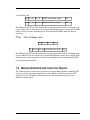
S200 Position Node with CANOpen/
DeviceNet
Installation Manual
M-SS-S2-11
Revision J June 25 2007
Keep all product manuals as a product component during the life span of the servo amplifier.
Pass all product manuals to future users/owners of the servo amplifier.
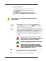
NOTICE:
1.) This S200 Option requires the use of special user interface software called S200 OC Tools. This
software can be installed using the included CD ROM. This device will not communicate with the
standard S200 Tools software.
2.) Common Problems
a.) If all dip switches are set to ON (Toggled to the right), the unit enters a perpetual rest state and
does not communicate. Change dip switch settings.
b.) When selecting a non-SFD motor, be certain to enter the ‘motor poles’ data.
c.) Always remember to Save the configuration to Non-volatile memory.
d.) Remember that COLDSTART is required before using the drive after changing I/O configuration.
Helping you build a better machine faster.
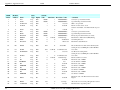
Record of Revisions
Date
Issue
2/1/07
D
2/19/07
E
4/4/07
F
5/21/07
G
6/13/07
H
6/25/07
J
Description
Revised Input definitions
Major rewrite
Added Modbus information
Made clarifications in Modbus Section
Added Page Numbers, modified encoder input circuit
Corrected J12 pin-out information
©2006 Danaher Motion - All rights reserved. Printed in the USA.
NOTICE:
Danaher Motion® is a registered trademark of the Danaher Corporation. Danaher Motion makes every
attempt to ensure accuracy and reliability of the specifications in this publication. Specifications are
subject to change without notice. Danaher Motion provides this information "AS IS" and disclaims all
warranties, express or implied, including, but not limited to, implied warranties of merchantability and
fitness for a particular purpose. It is the responsibility of the product user to determine the suitability of
this product for a specific application.
Safety Symbols
WARNING
CAUTION
NOTE
Warnings alert users to potential physical danger or harm. Failure to follow warning
notices could result in personal injury or death.
Cautions direct attention to general precautions which, if not followed, could result in
personal injury and/or equipment damage.
Notes highlight information critical to your understanding or use of the product.
Safety
WARNING
READ these instructions before connecting power. Damage can result from MISWIRING at the
power terminals.
DANGEROUS voltages are present on power input and motor output terminals.
Only qualified personnel are permitted to transport, assemble, commission, and maintain this equipment. Properly
qualified personnel are persons who are familiar with the transport, assembly, installation, commissioning and
operation of motors, and who have the appropriate qualifications for their jobs.
Read all available documentation before assembling and using. Incorrect handling of products described in this
manual can result in injury and damage to people and/or machinery. Strictly adhere to the technical information
regarding installation requirements.
Keep all covers and cabinet doors shut during operation.
Be aware that during operation, the product has electrically charged components and hot surfaces. Control
and power cables can carry a high voltage, even when the motor is not rotating.
Never disconnect or connect the product while the power source is energized.
After removing the power source from the equipment, wait at least 5 minutes before touching or
disconnecting sections of the equipment that normally carry electrical charges (e.g., capacitors, contacts,
screw connections). To be safe, measure the electrical contact points to each other and to electrical safety
earth with a meter before touching the equipment.
Danaher Motion
07/06
Table of Contents
Table of Contents
1
2
Table of Contents .................................................................................................. i
Product Overview ................................................................................................. 1
1.1
Highlights ................................................................................................... 1
1.2
Increased Machine Throughput & Longer Life ........................................... 3
1.3
Reduced Engineering & Support Time ...................................................... 3
1.4
CE- / UL- Conformity.................................................................................. 3
1.5
Model Number Scheme ............................................................................. 3
1.5.1 Valid Drive Model Numbers ............................................................ 4
1.6
Specifications............................................................................................. 5
1.6.1 Drive Family Power ......................................................................... 5
1.6.2 AC Input Drives - Control and Power .............................................. 7
1.6.3 DC Input Drives - Control and Power .............................................. 8
1.6.4 Velocity Loop................................................................................. 10
1.6.5 Mechanical.................................................................................... 10
1.6.6 I/O Specifications .......................................................................... 11
1.6.7 Environmental ............................................................................... 12
1.6.8 Smart Feedback Device (SFD) ..................................................... 12
1.6.9 Emulated Encoder Output Signals ................................................ 12
1.6.10 Current Loop ................................................................................. 12
1.6.11 General ......................................................................................... 13
Getting Started ................................................................................................... 14
2.1
Unpacking and Inspecting........................................................................ 14
2.2
Mounting .................................................................................................. 14
2.2.1 Dimensions ................................................................................... 15
2.2.2 Mounting Outline ........................................................................... 16
2.3
S200 Position Node AC Drive Wiring Diagram ........................................ 17
2.4
S200 Position Node DC Drive Wiring Diagram ........................................ 18
2.5
Connectors .............................................................................................. 19
2.5.1 J1 – AC Input Power Models Drive Power .................................... 19
2.5.2 J1 – DC Input Power Models Drive Power Connector................... 22
2.5.3 DC Input Power Model Power Supply Requirements.................... 25
2.5.4 Control Voltage ............................................................................. 26
2.5.5 Grounding ..................................................................................... 26
2.5.6 Bus Capacitance ........................................................................... 27
2.5.7 Bus Switching and Fusing............................................................. 28
2.6
J2 – Motor Power Connector ................................................................... 28
2.7
J3 – Feedback Connector........................................................................ 29
2.8
J4 – Command I/O Connector ................................................................. 31
2.8.1 Base Drive Unit General Purpose Inputs ...................................... 32
2.8.2 Base Drive Unit Outputs................................................................ 37
2.8.3 SFD BAT+..................................................................................... 39
2.8.4 DAC Monitors................................................................................ 39
2.8.5 Encoder Outputs ........................................................................... 39
2.8.6 J11 ................................................................................................ 40
2.8.7 J12 ................................................................................................ 42
2.8.8 J13 ................................................................................................ 44
2.8.9 Switch Settings.............................................................................. 45
S200 Position Node with CANOpen/ DeviceNet
i
Table of Contents
07/06
Danaher Motion
2.8.10 LED2..............................................................................................46
Operational Notes ...............................................................................................47
3.1
Encoder Input Channels ...........................................................................47
3.2
Pulse (Step) and Direction........................................................................48
3.3
Digital Input Notes ....................................................................................48
3.4
Ramp Control ...........................................................................................49
3.5
Homing .....................................................................................................50
3.6
Saving Drive Settings ...............................................................................50
3.7
Configuring Drive from Existing File .........................................................51
3.8
Upgrading Firmware Procedure................................................................52
4
Faults and Errors.................................................................................................54
4.1
CAN Bus Status Indicator.........................................................................54
4.2
Normal indicator operation .......................................................................54
4.3
Clearing Fault Conditions .........................................................................55
4.4
Conditional Settings..................................................................................55
4.5
S200 Position Controller Faults ................................................................55
4.6
Extended Fault Information ......................................................................56
4.7
S200 Base Unit Faults (b-faults)...............................................................58
4.8
System Warnings .....................................................................................59
5
Setup Software....................................................................................................60
6
System Tools ......................................................................................................68
6.1
Status Screen ...........................................................................................68
6.2
Communication Wizard ............................................................................69
6.3
Variable Editor ..........................................................................................69
6.4
Digital Oscilloscope ..................................................................................70
6.5
Configuration Summary Screen................................................................71
7
Serial Communications and Modbus RTU ..........................................................72
7.1
General information ..................................................................................72
7.2
Abbreviations............................................................................................72
7.3
RS232 Serial Port Configuration...............................................................73
7.4
Exception Messages ................................................................................73
7.5
Communication Strategy ..........................................................................74
7.6
ModBus functions .....................................................................................75
7.6.1 Reading Variables .........................................................................75
7.6.2 Writing Variables............................................................................76
7.6.3 Example: Read the ACC parameter ..............................................77
7.6.4 Example: Write the ACC parameter...............................................77
7.6.5 Example: Change Speeds in Digital Velocity Mode .......................78
7.7
Manufacturer specific function Codes.......................................................79
7.7.1 Command functions .......................................................................79
7.7.2 Command Execution: FC 65..........................................................79
7.7.3 Command execution status ...........................................................80
7.7.4 Drive Status ...................................................................................80
7.7.5 Set Motion Task.............................................................................81
7.7.6 Clear All Motion Tasks ...................................................................82
7.8
Mobus Address and function Tables ........................................................82
Appendix A - Cables ......................................................................................................89
Long Cables ........................................................................................................89
Custom Composite Cables..................................................................................89
Appendix B - Regulatory Information .............................................................................91
B.1 Conformance Requirements.....................................................................91
B.2 CE Approval .............................................................................................91
3
ii
S200 Position Node with CANOpen/ DeviceNet
Table of Contents
07/06
Danaher Motion
B.3
CE EMC Compliance ............................................................................... 91
B.3.1. CE Test Setup............................................................................... 92
B.3.2 CE Test Setup ............................................................................... 93
B.4 Declaration of Conformity................................................................. 94
B.5 Installation and Commissioning ............................................................... 96
B.6 Safety requirements................................................................................. 96
B.7 European Compliance ............................................................................. 96
B.9 UL and cUL Conformance ....................................................................... 98
B.10 Additional Safety Precautions .................................................................. 98
B.9 EMC Compliance with EN61800-3 .......................................................... 99
B.10 AC Mains Conducted Emissions............................................................ 100
B.11 Regen Resistor ...................................................................................... 102
B.12 Additional EMC Information Sources ..................................................... 102
Sales and Service............................................................................................. 103
iii
S200 Position Node with CANOpen/ DeviceNet
1 PRODUCT OVERVIEW
TM
The S200 Position Node with CANOpen/DeviceNet brings greater flexibility
to the S200 drive platform by adding profile generation and field bus
capabilities. It also brings added I/O, Digital Oscilloscope emulation, and the
ability to use incremental encoder with commutation tracks (ComCoder) for
motor feedback.
The S200 Position Node brushless position node servo drives with CANOpen
push high performance servo technology into lower power applications than
was previously possible without having to compromise on reliability or package
size. Couple a S200 position node drive with an AKM servo motor for a
complete servo control solution designed to excel in applications such as
semiconductor fabrication, electronic assembly, packaging, medical, and
woodworking equipment.
The S200 position node servo drives with CANOpen communication are the
first all digital industrial drives with a velocity loop bandwidth up to 800 Hz
offering unmatched system throughput and simplified tuning. High resolution
(24 bit) feedback and high performance 3-5 kHz current loop bandwidth
provide smooth motion and rapid start and stop action to optimize machine
performance. Smart feedback and industry leading high bandwidth deliver fast
and accurate commissioning by eliminating the need for servo loop tuning in
most applications.
A separate "keep alive" power input allows rapid recovery from emergency
stop conditions. Optically isolated inputs/outputs, positive locking connectors
and full fault protection promise long machine life and immunity to accidental
damage. A single motor power/feedback cable simplifies connectivity. All
connectors and LED status indicators are easily accessible from the front of the
drive.
1.1 HIGHLIGHTS
DC or AC input voltage:
DC type: 20 V ... 90 V
AC type: 110 V ... 240 V, 1Ø or 3Ø, 50/60 Hz
Highest performance all digital servo in the industry
Operation and Setup via a PC using the S200 OC Tools setup software
Easy set up and tuning with Smart Feedback Device
Optimized performance with AKM motors
Rugged optically isolated I/O
UL508C recognition, CE (EN50178, EN61800-3)
Very compact footprint
Full fault protection
Velocity, Position, and Electronic Gearing control standard
Indexing - 180 unique motion tasks can be defined and initiated via the serial port
or discrete inputs
Relative, Absolute, Simple Registration, and Home motion tasks can be easily
setup and executed
Individual motion tasks can be linked with each other
Digital Oscilloscope Functions for improved tuning
Built-in CANOpen / DeviceNet Communication bus
1
Flash memory allows for quick and easy firmware updates via the serial interface
Incremental Encoder Input port allows ComCoder motor feedback for position
loop control.
2
1.2 INCREASED MACHINE THROUGHPUT & LONGER LIFE
Servo system performance is synonymous with machine throughput. The S200
POSITION NODE family takes servo performance to new heights.
Industry-leading current loop bandwidth up to 5 kHz and velocity loop
bandwidth up to 800 Hz means machine throughput can be increased by as
much as 2 to 3 times.
Robust design including full fault protection, locking connectors and optical
isolation promise greater machine “up-time”.
Smooth motion, a benefit of sinusoidal current control and high resolution (24
bit) feedback minimizes harsh torque disturbances that can cut short the life
of mechanical components.
Both the AC and the DC input drives are equipped with separate control
power input to speed recovery from “E-Stop” conditions.
CANOpen Field Bus or DeviceNet communications
1.3 REDUCED ENGINEERING & SUPPORT TIME
Simplified tuning, friendly Graphical User Interface and shared components with
Stepper products.
Windows-based Graphical User Interface models the tree format found in Explorer so
learning is quick and easy.
Digital Oscilloscope emulator for easier setup.
Easy to debug with full fault diagnostics reduce engineering support time.
Field bus connectivity.
1.4 CE- / UL- CONFORMITY
The S200 position node with CANOpen meets all relevant standards:
EMC Directive 89/336/EWG, standard used ENG61800-3
Low Voltage Directive 73/23/EWG, standard used 50178
UL / cUL 508C recognized
1.5 MODEL NUMBER SCHEME
S2 03 3 0 CN S - 002
Customization - omit for standard drives
000 - 019 Reserved for factory use only
020 - 999 Reserved for customers only
Family
S2 - S200 Servo Family
Current Rating
02 - 1.5 A RMS continuous,
4.5 A RMS peak
03 - 3 A RMS continuous,
9 A RMS peak
06 - 6 A RMS continuous,
18 A RMS peak
Feedback Support
S - SFD/Halls - Base Unit
SFD/Comcoder - CAN option card
Smart Feedback Device (SFD) - SynqNet Option Card
Sine encoder - SynqNet Option Card
EnDat 2.1 - SynqNet Option Card
Voltage
3 - 20-90 VDC
5 - 120 VAC doubler/240 VAC 1-phase
6 - 120/240 VAC
Electrical Option
0 - No Electrical Option
3
Functionality
VT - Velocity/Torque modes
DN - Position Node w/DeviceNet Interface
CN - Position Node w/CANOpen Interface
SD - SynqNet option card w/ micro-D connectors
SR - SynqNet option card w/ standard RJ connectors
1.5.1
Valid Drive Model Numbers
DC Input Power Drive Models
S20330-VTS: 90 VDC, 3/9 ARMS Base Unit
S20630-VTS: 90 VDC, 6,18 ARMS Base Unit
S20330-CNS: 90 VDC, 3/9 ARMS Base Unit, CAN/Indexer option card
S20630-CNS: 90 VDC, 6/18 ARMS Base Unit, CAN/Indexer option card
S20330-SRS: 90 VDC, 3/9 ARMS Base Unit, SynqNet option card with RJ-45
connectors
S20630-SRS: 90 VDC, 6/18 ARMS Base Unit, SynqNet option card with RJ-45
connectors
S20330-CNS: 90 VDC, 3/9 ARMS Base Unit, SynqNet with Micro-D connectors
S20630-SDS: 90 VDC, 6/18 ARMS Base Unit, SynqNet with Micro-D connectors
AC Input Power Drive Models
S20250-CNS: 120VAC doubler/240VAC, 1 phase, 1.5/4.5 ARMS Base Unit, Profile
Node with CanOpen
S20250-DNS: 120VAC doubler/240VAC, 1 phase, 1.5/4.5 ARMS Base Unit, Profile
Node with DeviceNet
S20260-CNS: 120/240 VAC, 1/3-phase, 1.5/4.5 ARMS Base Unit, Profile Node
with CanOpen
S20260-DNS: 120/240 VAC, 1/3-phase, 1.5/4.5 ARMS Base Unit, Profile Node
with DeviceNet
S20350-CNS: 120VAC doubler/240VAC, 1 phase, 3/9 ARMS Base Unit, Profile
Node with CanOpen
S20350-DNS: 120VAC doubler/240VAC, 1 phase, 3/9 ARMS Base Unit, Profile
Node with DeviceNet
S20360-CNS: 120/240 VAC, 1/3-phase, 3/9 ARMS Base Unit, Profile Node with
CanOpen
S20360-DNS: 120/240 VAC, 1/3-phase, 3/9 ARMS Base Unit, Profile Node with
DeviceNet
S20650-VTS: 120VAC doubler/240VAC, 1/3-phase 6/18 ARMS Base Unit
S20650-SRS: 120VAC doubler/240VAC, 6/18 ARMS Base Unit, SynqNet option
card with RJ-45 connectors
S20650-SDS: 120VAC doubler/240VAC, 6/18 ARMS Base Unit, SynqNet with
Micro-D connectors
S20650-CNS: 120VAC doubler/240VAC, 6/18 ARMS Base Unit, Profile Node with
CanOpen
S20650-DNS: 120VAC doubler/240VAC, 6/18 ARMS Base Unit, Profile Node with
DeviceNet
S20660-VTS: 120/240 VAC, 1/3-phase 6/18 ARMS Base Unit
S20660-SRS: 120/240 VAC, 1/3-phase 6/18 ARMS Base Unit, SynqNet option
card with RJ-45 connectors
S20660-SDS: 120/240 VAC, 1/3-phase 6/18 ARMS Base Unit, SynqNet with
Micro-D connectors
S20660-CNS: 120/240 VAC, 1/3-phase 6/18 ARMS Base Unit, Profile Node with
CanOpen
S20660-DNS: 120/240 VAC, 1/3-phase 6/18 ARMS Base Unit, Profile Node with
DeviceNet
4
1.6 SPECIFICATIONS
Unless otherwise specified, the specifications are worse case
limits and apply over the specified operating ambient
temperature and over the specified operating line voltage.
NOTE
1.6.1
Drive Family Power
!
!
"
#
#
!
!
!
!
$
! $
" $(
$ %
$ %
$
$ % )&
$ % )&
! $ % )&
" $( *
&
&
#
!
"
'
*
*
*
'
!
"
*
*
'
'
)&
)&
)&
% +,)/ 0
0#
) .)* .
1
)* *
3 (-4 45 6
$ 5
- 2
$
1 1 2 03 4
$( 8
59:
" $( 9: * & % ;
+5
$(
# 6 7! 89
:1 1 #
;# 8
" $(
"
'
'
'
'
'
'
!
!"
(
'
'
!
!
. /
5
'
#$ % & '
"
'
'
"
!
'
-) .
'
#
!
(
! $
! $
! $
)$*
+
,
!
'
'
"
#2
#2
#2
#
#
!
!
'
'
!
'
'
#
#
#
! 2
! 2
! 2
2
2
2
! 7
5 #
! 7
!7
'
'
!
'
!
!
!
'
!
!
'
'
!
'
'
'
'
'
'
!"
#"
!
!
'
'
'
'
'
'
'
'
'
'
!
'
!
'
!
1
2
3
4
Peak Output Current listed is for sine mode. In six-step mode, the peak output currents are scaled to give the
same output torque as in sine mode with a pure sinusoidal Back EMF motor.
To convert ARMS to A(0-pk), multiply ARMS * 1.414.
For Operation above Above 40o C ambient: Derate linearly to 67% at 50o C .
At higher ambient temperatures (above 30o C) the S20360 drive needs to be mounted on a thermally conductive
surface to limit the heatsink temperature to less than 75o C.
Single phase operation of the S20660 requires derating of continuous output power to avoid excessive AC line
front-end currents.
See Appendix – Cables for voltage loss vs cable length.
<
<
:1
1<
1<
6
5
5
1#
;# 8
4# ( 0
"
.
!
1.6.2
AC Input Drives - Control and Power
#
#
3
$
- #0
:
0
0
"
!
!
(
!
!
!# $
5 &
# =>
$(
" $(
$
# =>? " # => 45
$
# =>?
# => 45
$
# =>?
# => 45
#
3
- #0
0
-
!#
!
00
:=!
<
( =- &
1
Maximum AC Line is specified to limit the mains surges to the drive.
$
. &
$* * :
$*
$*
0
- #0
"
#$ - # 0
"
#$ - # 0
#0 6 #
#0 $
- 6 #
- #0
:6 #
! $(
$(
@
4( -5 8
" $( A 6
B " C9-D$ B " $( 8
>6
?
1
3
!
!
!
'
:
: :6
0(
% , $
)&
$
)&
$
)&
#36
999-
( '
( '
( '
999-
#
?
1
0%
( '
( '
( '
>6
. -
#
6
0
. #
:
#
#
9-
7
#:
9-
( '
9-
( '
0
'
#3
#
5
#
!
( 7 E
!
1.6.3
DC Input Drives - Control and Power
#
5$ 5
$(
F'
F'!
A
A
5, - * *
!
1
(20 watt min supply recommended) Refer to the DC Power Supply Section for detailed
application information and requirements.
$* - # 0
A9: $ 5
$(
A9: :
+ 5 @ -5
A9: D+ + 5 @ -5
F'
:6 #
F'!
A!
A
A " $(
A $(
5
5
#3
5) *
5
( +D
5
#
)&
3
'
1 +
,
0HC( + ,
@9
!
7
) .&
*
-5 5
40H 4 #
)
,
-
)- -
0
5
0
0
*
0H 8' E
C( + ,
0H 8' E
C,
@9
$ : :
6
-5
)
;
:: <
, - ( + =>
( , - ( + =>
8
!
J
!
K!
- +5
2#1 1 #6 7
3
'
%
. +
1
<
:
1
5
0
(
$ : :
, -( + .
=>
( , -( + .
=>
1
: :$ : :
, -( + .
=>
( , -( + .
=>
@( .
=>
I(
9 * &$
@ @3
-
G- B
13 89
#
.
!
!
3 1#
!6 E !
!6 E!
!6 E!
!6 E
9
?
6 E#
6 E#
6 E#
6E!
1.6.4
Velocity Loop
:
3 )
59
;
* & =>* & @(
%
5
-
L
5
5
- #1 3(
0$)
(
, .
# , . E E
0$)
5
6
0$,
=>
? !!
0$,
5
6
@
=>
!
? ##!"
@
=>
!
? ##!"
1
Values for ARF0, ARF1; from 3012 to 24873 Hz cannot be set.
1.6.5
Mechanical
" *
-2
;;-
( +=
&
( +1
&9
( +(
&
0
8 :
? 0
1
!
#
! "
" *
;@@
;@@
!
#
"
;;-
;@@
"
#
#
! !
#
-2
;@@
;@@
"
#
"
#
! #
#
! #
#
"
M
M
.
5
.
5
M
!.
5
"*&
M
M
"" .
# 5
.
#5
Depth measurement is for drive only. Add approximately 50.8 mm (2 in) to depth given in the table
to accommodate mating connectors and wire bend radius.
10
1.6.6
I/O Specifications
Analog command is not allowed in this product. Digital Velocity and Motion
Task position loop control is the only possibilities.
#0
"&A
1
" B
. &.A
&,
3 +5
@-5
5 5H 5
6
H4 51
J
4 6 @-5
5 5
D
D
7
AE
'
L
L !'
L
!
$
(
;$E
4
C
C
:
H4
, -$ 5
, -H
3 - J
@ G-
4
#
(,
8) D
@-5
5
5
8 $ B& ;&.A
&,
5
5
!
%HHJ
%(
=>G-
5
-
-5
0 #
" &;.A "
, -$ 5
#
:
8
B& ;& A&
' !!E '
3 ND
5
3
#! .
=>
D
K
;E B. ;.
K
'
:B&
+5
;,
F'
, - -
# '#"
H
" ,F " &
8 "
, -$ 5
, - -
D
; B.;& > &&AB& G> E
7 # +5
7!
#
* &A
3 - D- - $ 5
5 $ 5
3 - D- - D +5
*
'
B.; A
+
:B.;GA
E
+5
+ 5K #6
+5
! +5
H
C
C :
H4
D- - $ 5
=4
11
:
8 ; B.;&EA
8 $; B.; &A
' !!E '
$(
5D- - ' : 5
E
! OE/
8H; B.;&+A
&G
J
-
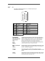
1.6.7
Environmental
D
D
J
H
-
H
7(
-- -
5
4(
)5
5
-
7 @-5
5
7
#"6
(
!
H
=-
-
46
'!
'
5-
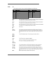
1.6.8
"
L
Smart Feedback Device (SFD)
5
-
E +
!
B
'
54
LK !
+B K
"
8 @5
=>
=>
5 ) 5 @5
5 ) 5 @5
!
!
4 #
0
0 !
11
L!
+
+
+
+
E
B
B
B
#
!
B
E
13
K !'
K !'
%
:
)
;
+B K "
+B K
!
Emulated Encoder Output Signals
#4#
9 4
(
5
#
! % !% ! %!
! % %
%!
3 - D- - J
@ G-
%
%!
4 =>
!
3
!"# ))
!!
3
#
3
))
#%
%
!% #
%
#
# ))
. )-5 1
&
P O-
1.6.10 Current Loop
12
"
'
!
-
1.6.9
L !'
L !'
L !'
'
99
'
)&
* & =>
?!
J
?
=>
- )-5
% !"#
%!
1.6.11 General
3H
.
?
3
3H
!
.
3 - @
13
#
5
.
E
5J
&
? #3
#
#
2 GETTING STARTED
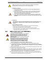
2.1 UNPACKING AND INSPECTING
Open the box and remove all the contents. Check to ensure there
is no visible damage to any of the equipment.
CAUTION
CAUTION
NOTE
Use proper procedures when handling electronic
components to avoid damage to equipment.
Remove all packing material and equipment from
the shipping container. Be aware that some
connector kits and other equipment pieces may
be quite small and can be accidentally discarded.
Do not dispose of shipping materials until the
packing list has been checked.
Upon receipt of the equipment, inspect
components to ensure that no damage has
occurred in shipment. If damage is detected,
notify the carrier immediately. Check all shipping
material for connector kits, documentation,
diskettes, CD-ROM, or other small pieces of
equipment.
2.2 MOUNTING
The S200 drives are designed for operation in a cabinet using the following
installation instructions:
Mount the drives vertically inside a cabinet on a flat, solid, electrically
conductive, mounting surface connected to PE (protective earth ground) and
capable of supporting the weight of the unit.
Provide a good connection to PE. Remove the paint on the mounting surface
over an area extending at least 12 mm (0.5 in) from the mounting bolts to
achieve good electrical connection over a large area between the drive and
grounded mounting surface.
Insure the environment within the cabinet meets the requirements listed in the
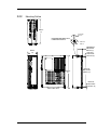
environmental specifications table.
14
2.2.1
Dimensions
" *
" *
-2
!
#
( +=
&
( +1
&9
( +(
&&
#
H
-2
"
#
#
! !
#
"
#
!"
!
!
!"
!
!
! #
! #
"
#
# #"
"
#
"
#
# #"
! #
#
"
1
7
9
(
/
0
= >
5 -
D
@
$
5 -
D
$
5 -
= & =
( +
( +
-
08 :
! #
"
<
F
#
#
#
#
!
#
M
M
M
.
.
.
? 0
5
5
#5
1
Depth measurement is for drive only. Add approximately 50.8 mm (2 in) to depth given in
the table to accommodate mating connectors and wire bend radius.
15
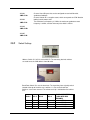
2.2.2
Mounting Outline
DEPTH
(C)
0.18 mm
4.57 in
RECOMMENDED MOUNTING
HARDWARE M4 OR #8
F
TOP VIEW
0.18 mm
4.57 in
HORIZONTAL
MOUNTING
OFFSET (F)
WIDTH
(B)
VERTICAL
MOUNTING
OFFSET (G)
VERTICAL
MOUNTING
HEIGHT (H)
HEIGHT
(A)
VERTICAL
MOUNTING
OFFSET (G)
FRONT VIEW
16
RIGHT SIDE VIEW
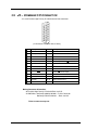
REAR VIEW
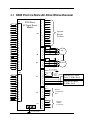
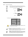
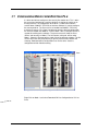
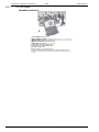
2.3 S200 POSITION NODE AC DRIVE WIRING DIAGRAM
J4
DINP COM
DINP1
DINP2
DINP3
DINP4
DOUT 1 DOUT 1 +
DOUT 2 DOUT 2 +
DINP5 +
DINP5 NC
I/O RET
DAC MON 1
DAC MON 2
I/O RET
CH Z OUT
CH Z OUT
CH A OUT
CH A OUT
CH B OUT
CH B OUT
I/O RET
ANA CMD +
ANA CMD I/O RET
1
2
3
4
5
6
7
8
9
S200 Drive
AC Input Power
Models
J13
12
13
14
15
10
11
12
13
14
15
16
17
18
19
20
21
22
23
24
25
26
J3
J2
J12
DINP COM
DINP6
DINP7
DINP8
DINP9
DOUT 3 +
DOUT 3 DINP 10+
DINP10 5V Source
5V COM
CH A / Step
CH A / Step
CH B / DIR
CH B / DIR
1
2
3
4
5
6
7
8
9
10
11
12
13
14
15
1
2
3
4
5
6
7
8
9
10
11
J1
1
2
3
4
5
6
1
2
3
4
1
2
3
4
5
6
7
8
9
J5
J11
1
2
3
4
5
6
1
2
3
4
5
Protective Earth
17
CU
CV
CW
I/O RET
CH Z IN
CH Z IN
Optional
Encoder
Feedback
PTC
PTC RET
5V SOURCE
I/O RET
CH A IN
CH A IN
CH B IN
CH B IN
+5V
5V RET
SFD
SFD COM SFD COM+
PE
PE
W
W
V
V
U
U
MOTOR
Protective Earth
REGEN
BUS -
NC
BUS+
C1 CNTL
Optional
Regen
Resistor
C2 CNTL
L3
120/240VAC Control
Power 47-63Hz Fused
120/240VAC Mains
47-63Hz Fused
L2
L1
NC
RX Data
I/O RET
I/O RET
Tx Data
RS 232
Configuration
Port
NC
V+
CAN H
SHIELD
CAN L
V-
Optional
CanBus
Connection
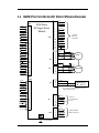
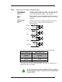
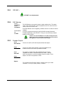
2.4 S200 POSITION NODE DC DRIVE WIRING DIAGRAM
J4
DINP
DINP
DINP
DINP
DINP
DOUT 1
DOUT 1
DOUT 2
DOUT 2
DINP5
DINP5 NC
I/O RET
DAC MON 1
DAC MON 2
I/O RET
CH Z OUT
CH Z OUT
CH A OUT
CH A OUT
CH B OUT
CH B OUT
I/O RET
ANA CMD
ANA CMD I/O RET
1
2
3
4
5
6
7
8
9
10
11
12
13
14
15
16
17
18
19
20
21
22
23
24
25
26
S200 Drive
DC Input Power
Models
J13
J3
J2
J12
DINP
DINP
DINP
DINP
DINP
DOUT 3
DOUT 3
DINP
DINP10 5V Source
5V COM
CH A / Step
CH A / Step
CH B / DIR
CH B / DIR
1
2
3
4
5
6
7
8
9
10
11
12
13
14
15
J1
1
2
3
4
5
6
1
2
3
4
1
2
3
CU
CV
CW
I/O RET
CH Z IN
CH Z IN
Optional
Encoder
Feedback
PTC
PTC RET
5V SOURCE
I/O RET
CH A IN
CH A IN
CH B IN
CH B IN
+5V
5V RET
SFD
SFD COM SFD COM+
PE
PE
W
W
V
V
U
U
MOTOR
+ CNTL
BUS/CNTL GND
+ BUS
Main Power
20 – 90 VDC
Note: J1 Pin 2 and all I/O RET pins are tied
together within the drive.
J5
J11
Protective Earth
18
1
2
3
4
5
6
7
8
9
10
11
12
13
14
15
1
2
3
4
5
6
1
2
3
4
5
RX Data
I/O RET
I/O RET
Tx Data
NC
RS 232
Configuration
Port
NC
V+
CAN H
SHIELD
CAN L
V-
Optional CAN
Bus Connection
2.5 CONNECTORS
2.5.1
J1 – AC Input Power Models Drive Power
The S200 AC input drives are capable of direct line operation. All
units are fully isolated and do not require external isolation
transformers. The inrush current on the connection to the line is
internally limited to a safe level for the drive. There are no voltage
selection or ranging switches required to operate within the specified
voltage input ranges.
The S200 series drives are functionally compatible with all standard
forms of three phase AC lines:
Grounded neutral WYE
Open-Delta Grounded Leg
TEE
NOTE
It is the customer’s responsibility to supply appropriate
fuses or circuit breakers in the J1 AC drive power lines to
comply with local electrical codes.
The control input power required is between 5 and 10 watts. The AC
motor input power depends on output power and losses in the power
stage.
On AC input drives, J1 is a 9-pin plugable connector.
1
9
(J1 Connector view from front of drive).
Pin
J1-1
J1-2
J1-3
J1-4
19
Description
PE (Protective Earth) – Must be tied back to central earth bar.
REGEN - Model S20660 uses a 26 resistor. For all other models, the
chosen resistor must be rated for the appropriate peak power (400 V ^2 / x
). For example, 25 to 50 for the S20260 and 20360 drives or 15 to 50
for the S20630 and S20330.
-BUS DC – Internal DC Bus negative connection (Not normally used)
+BUS – Internal DC Bus Positive Connection (Regen Resitor Termination
Point)
J1-5
J1-6
J1-7
J1-8
J1-9
20
C2 CTRL VAC – Logic control Power
C1 CTRL VAC – Logic Control Power
L3 240 VAC – Main Line
L2 240/120 VAC – Main Line
L1 240/120 VAC – Main Line
J1 Mating Connector Information
Screw Terminal Connector:
12 – 24 AWG Wire Range, Phoenix MSTB2,5/9-STF-5,08-BK
OR Spring Cage Clamp Connector
12 – 24 AWG Wire Range, Phoenix FKC 2,5/9-SFT-5,08-BK
OR Crimp Connector
14-20 AWG Wire Range, Phoenix MSTBC 2,5/9-STZF-5,08-BK
Crimp Contact: 14-16 AWG Wire Range, Phoenix MSTBC-MT 1,5-2,5
Crimp Contact: 18-20 AWG Wire Range, Phoenix MSTBC-MT 0,5-1,0
Refer to www.phoenixcon.com.
CAUTION
To avoid damage to the connector and drive, NEVER plug or unplug J1
with power applied.
J1-1 PE
Protective
Earth
Protective Earth: This chassis ground point must be connected to
Protective Earth ground. The connection at the Protective Earth ground end
must be hard wired (do not use a plugable connection). A ground fault
detector (RCD) cannot be depended on for safety.
J1-2
REGEN
Connection for an optional regeneration power resistor to absorb regenerated
energy from the motor. Models S20260, S20360 use 36 . Use a Wire wound
resistor with 1500 VRMS isolation between terminals and case. Many
applications do not require a regen resistor. If over-voltage faults occur during
motor deceleration, connect the proper ohm 50 to 300 watt power resistor
from this terminal to terminal J1-4 (+BUS). The power rating of the regen
resistor depends on the amount of regenerated energy that needs to be
dissipated.
WARNING
NOTE
WARNING
21
The Regen input is not short circuit protected. The Regen
Resistance MUST be within specified ranges to prevent
damage to the drive. For example, between 25 to 50 for the
S20260, S20360 drives or 15 to 50 for the S20660.
For safety, either mount the external resistor on a grounded
panel or wire it to a grounded connection. The terminals of
the resistor MUST NOT be grounded.
Wait 5 minutes after power is removed for the bus cap
voltage to decay to a safe level before touching the regen
resistor or wiring. Monitor the voltage on the bus caps with a
voltmeter from +BUS (J1-4) to -BUS (J1-3).
J1-3
-BUS
The -BUS terminal is usually left open during normal operation. In special multiaxis applications drive buses can be wired in parallel to allow returned energy
from one motor to power another and limit high regen powers.
J1-4
+BUS
The +BUS terminal is used with the J1-2, REGEN, terminal to add a regen
resistor to the drive to absorb regenerated energy.
NOTE
After powering down the drive, monitor the BUS voltage by connecting a
meter from J1-4 (+BUS) to J1-3 (-BUS) to verify the internal BUS capacitors
have discharged prior to working on the drive.
J1-5, J1-6
C2 CTRL VAC
C1 CTRL VAC
These terminals connect 120/240 VAC power to the drive’s control voltage
power supply.
- #0
#
6
0
:
$
!# $
"
# =>
! $(
" $(
5 &
' * &!
, -
$
#
0
9-
( 7Q
For maximum ride through capability a 240 VAC input is recommended.
NOTE
J1-7, J1-8, J1-9
L3 240 VAC
L2 240/120 VAC
L1 240/120 VAC
These terminals connect 120/240 VAC power to the drive’s output power
stage BUS.
For single phase operation 120/240 use inputs J1-8, L2, and J1-9, L1.
- #0
0
!
!# $
!
<
(
#
0$ 7
0$ &
' * &!
0$
$
-
:
6
0
! $
)&
9( '
9( '
9! $
)&
9( '
9( '
9! $
)&
9( '
9( '
91
Maximum AC Line is specified to limit the mains surges to the drive.
2.5.2
J1 – DC Input Power Models Drive Power Connector
The S200 DC input drives should be powered from power supplies with
reinforced isolation.
On DC input drives, J1 is a 3 pin plugable connector.
22
G-
( '
( '
( '
Pin
3
1
(J1 Connector view
from front of drive).
Description
J1-1
+CTRL
J1-2
BUS/CTRL GND
J1-3
+BUS
To avoid damage to the connector and drive, NEVER plug or
unplug J1 with power applied.
CAUTION
Mating Connector Information
Screw Terminal Connector
12 – 24 AWG Wire Range, Phoenix MSTB2,5/3-STF-5,08-BK
OR Spring Cage Clamp Connector
12 – 24 AWG Wire Range, Phoenix FKC 2,5/3-SFT-5,08-BK
OR Crimp Connector
Crimp Shell: 14-20 AWG Wire Range, Phoenix MSTBC 2,5/3-STZF-5,08BK
Crimp Contact: 14-16 AWG Wire Range, Phoenix MSTBC-MT 1,5-2,5
Crimp Contact: 18-20 AWG Wire Range, Phoenix MSTBC-MT 0,5-1,0
Refer to www.phoenixcon.com.
23
J1-1
+CTRL
Control power input. The DC drive accepts +10 to +90 VDC on this input
referenced to J1-2. An isolated regulated or isolated unregulated power
supply can be used. This input can be connected to +Bus input, J1-3, and
powered by the same supply as +Bus.
The control power supply should be rated for 20 watts. While the power
drain typically is 2 W to 8 W, a 20 W supply ensures reliable starting of the
drive.
J1-2
BUS/CTRL GND
Power return for the control and BUS power supplies. The BUS/CTRL
GND is connected to I/O RTN internally in the drive.
J1-3
+BUS
Main power input to the drive. The DC drive accepts +20 to +90 VDC on
this input referenced to J1-2. An isolated regulated or isolated unregulated
power supply can be used. The +Bus power drain with +Bus voltage at 75
VDC is in the range shown below. It varies according to the application
and motor.
)$
)$
!
"
*
*
*
% *
Refer to the DC Power Supply Requirements section for detailed
requirements selecting a compatible power supply.
NOTE
PE
Screw Connection
24
Protective Earth connection point. This chassis ground point must be
connected to Protective Earth ground. The connection at the Protective
Earth ground end must be hard wired (do not use a pluggable
connection).
2.5.3
DC Input Power Model Power Supply Requirements
$ - # 0 B&;
B&;
$*
#
3
!
-) .
! #
-) .
$*
1 1
!
! #
Bus Supply Characteristics
A ! $(
A
$(
.G$*
(
# 1
(
1
#" (
! 1
! (
# 1
.G$*
% ;%# $
% ;%# $
+,$*
(
! 1
(
" 1
#" (
1
! (
% 1
+,$*
!% ;%
$
% ;%
$
The BUS Supply should have the following characteristics:
Must provide safety isolation from the power line
Can be regulated or unregulated
Bus Supply Return is connected to the Control Supply
Return and I/O RTN in the drive
Typical BUS Supply:
Unregulated, Isolating, step down transformer with
secondary rectified into capacitive filter
BUS Supply Return is connected to earth ground
25
Wiring from BUS Supply to
Drive
10 ft maximum
16 AWG (minimum)
Twisted pair
Daisy chaining of multiple drive OK
No contactor or switching in the BUS wiring
Control Voltage
(J1-1 to J1-2)
+ 10 VDC to +90 VDC
Control Supply Type
Isolating
Unregulated or Regulated
Common GND with bus supply and I/O RTN
20 watt supply or 1 amp short circuit
Control Supply Wiring
Wire control (J1-1) to bus (J1-3)
or
Wire control (J1-1) to separate supply to preserve status and
fault information. (+ 10 VDC to + 30 VDC supply can be
shared by Control and I/O)
Control Supply Current
20 to 110 mA at 75 VDC
60 to 330 mA at 24 VDC
125 to 660 mA at 12 VDC
Bus Voltage
Bus voltage outside the operating range (20 to 90 V) causes
an under-voltage or over-voltage fault. Under-voltage and
over-voltage faults self clear when the fault condition clears.
NOTE
Do Not allow the Bus Voltage to exceed
+ 90 VDC. This causes damage to the
drive.
Target design center voltage for unregulated supply is +
70 to + 75 VDC. This provides 15 to 20 VDC margin for
line tolerance, transformer regulation, and regen pump
up. Design center voltage for a regulated supply can be
up to + 80 VDC.
2.5.4
Control Voltage
The control voltage range for normal operation is + 10 VDC to + 90 VDC. The
control voltage can either be wired to the bus voltage so one supply can power
the drive, or from a separate supply. Separately powering the control from the
bus allows the bus to be powered down for safety while drive status and fault
information remain available. A single + 10 VDC to + 30 VDC supply can be
shared by Control and I/O.
NOTE
2.5.5
Do Not allow the Control Voltage to exceed + 90 VDC as it can damage the
drive.
Grounding
Provide safety isolation with the external bus and control supplies from the
power line.
The drive cannot be powered from an electrically Hot supply as it does not
contain an isolation barrier.
NOTE
The Ctrl and Bus voltages and non-opto coupled I/O grounds (I/O RTN) are
tied together inside the drive. The Ctrl and Bus power supplies share a ground
pin (Bus/Ctrl Gnd). Join and connect to the negative terminals of the Ctrl and
Bus power supplies. The I/O RTNs are normally connected to the signal
ground of the system. (Some of the I/O is opto coupled and have separate
returns. Thoroughly review this document for details.)
Earth the power supply negative terminal somewhere in the cabinet. Also earth
the chassis. In normal operation, there should be no significant voltage
between earth and the Bus/Ctrl Gnd and I/O RTNs.
26
NOTE
2.5.6
The maximum voltage allowed between Bus/Ctrl Gnd and chassis is 100
VDC.
Bus Capacitance
There is a minimum requirement on the output capacitance of the bus power
supply for the DC input S200. This capacitor is needed to absorb energy during
motor deceleration and motor disable and to help provide energy during motor
acceleration. For multiple S200 drives operated from one supply the
recommendation is to increase the capacitance according to the number of
drives. For example, for four 6 A / 18 ARMS DC S200 drives powered from one
75 VDC supply the recommended minimum bus output capacitance of the
supply is 4 x 4,000 µf = 16,000 µf. Bus capacitor voltage rating should be 100
V. Bus capacitor type is aluminum electrolytic.
27
2.5.7
Bus Switching and Fusing
Do not put E-Stop switches or contactors between the drive bus pin (J1-3) and
the power supply bus capacitor. There is a risk of damage to the drive if the
bus is disconnected from the power supply capacitor when the drive is
enabled. The motor does not need to be rotating to regenerate energy. The
motor windings store magnetic energy that regenerates back to the supply
when the drive is disabled.
E-stop switches can safely be located in series with the primary winding of a
step down transformer. If individual axis E-Stop switches are required, connect
a local (unswitched) capacitor (1,000 µf, 100 V) across the drive bus terminals
(J1-3 to J1-2).
If the buses of individual drives are to be fused, select the fuse type and rating
for high margin.
S20630 (6 amp)
15 A, Slo-Blo (Bussmann MDA15)
S20330 (3 amp)
7 A, Slo-Blo (Bussmann MDA-7)
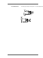
2.6 J2 – MOTOR POWER CONNECTOR
J2 is a 4 pin pluggable connector.
1
4
(J2 Connector view from front of drive).
1
F
!'
F
!'!
F
!'
F
!'
)/ &
< 9: EH J<8(
)& 1
)& $
)& :
!
!
, -( +
( , -( +
Mating Connector Information
Screw Terminal Connector: 12 – 24 AWG Wire Range, Phoenix MSTB2,5/4STF-5,08-BK
OR
Spring Cage Clamp Connector: 12 – 24 AWG Wire Range, Phoenix FKC 2,5/4SFT-5,08-BK
OR
Crimp Connector
Crimp Shell: 14-20 AWG Wire Range, Phoenix MSTBC 2,5/4-STZF-5,08-BK
Crimp Contact: 14-16 AWG Wire Range, Phoenix MSTBC-MT 1,5-2,5
Crimp Contact: 18-20 AWG Wire Range, Phoenix MSTBC-MT 0,5-1,0
Refer to www.phoenixcon.com
28
J2-1 PE
Motor Case
Ground
On S200 AC Input Drives this point is connected to Chassis Ground.
J2-2, 3, 4
Motor
Phases
These three terminals provide the 3-phase power output to the motor.
NOTE
Observe motor polarity, connect phase U on the drive to
phase U on the motor, etc.
For nonstandard motor drive combinations consult the
factory for proper phase orientation.
2.7 J3 – FEEDBACK CONNECTOR
J3 is a 6-pin plugable IEEE 1394 style connector for the feedback device.
Although this connector mechanically accepts standard IEEE 1394 cables, it is
electrically not an IEEE 1394 interface. The base drive accepts either SFD
(Smart Feedback Device) or Hall inputs.
1
2
3
4
5
6
(J3 Connector view from front of drive)
Pins
Description
J3-1
SFD +5 V (200 mA)
J3-2
SFD +5 RTN
J3-3
SFD COM-
J3-4
SFD COM+/CU
J3-5
NC/CV
J3-6
NC/CW
Shell
Shield Connection
Mating Connector Information
IEEE1394, Firewire type, 2.0 mm plug set
22 AWG Max., Molex 55100-0600
Refer to www.molex.com for assembly instructions.
29
30
J3 –1
SFD +5 V
This terminal provides a 5 VDC output to power the feedback device. For
example, motor equipped with SFD, Halls or commutation encoder.
The load current should not exceed 200 mA.
J3-2
SFD +5 RTN
This terminal is the return connection for the 5 VDC supply. An inner feedback
cable shield can be connected to this point. Outer shields should connect to the
shell which is PE.
J3-3
SFD COM-
SFD serial communications port when using the SFD feedback device.
No connection when using Hall feedback.
J3-4
SFD COM+ /
CU
SFD serial communications port when using the SFD feedback device.
CU (Commutation Phase U) input when using open collector Hall feedback.
This input has a 2.21 kΩ pull-up resistor to 3.3 volts.
J3-5
NC / CV
No connection when using the SFD feedback device.
CV (Commutation Phase V) input when using open collector Hall feedback. This
input has a 2.21 kΩ pull-up resistor to 3.3 volts.
J3-6
NC / CW
No connection when using the SFD feedback device.
CW (Commutation Phase W) input when using open collector Hall feedback.
This input has a 2.21 kΩ pull-up resistor to 3.3 volts.
Shell
Outer shield connection (wired to PE in the drive).
2.8 J4 – COMMAND I/O CONNECTOR
J4 is a 26-Position High Density D subminiature female connector.
26
19
18
10
9
1
(J4 Connector view from front of drive.)
1
1
F'
(,
8) D
F'!
(,
8) /
F'
(,
8)!
F'
(,
8)
F'
(,
)
F'#
(D:H '
F'
&
5/
F'"
(D:H A @-5
F'!
&
5A /
F'
(D:H!'
F'!
&
59/
F'
(D:H!A
&
5B /
F'
(,
8) A = ,
8) A
F'!
F'
(,
) 7 =,
8) '
F'!
F' !
F'
,
8)
@( 9 HA
,
E
D H8
5
:8
F'
(
D8
F'
(
D8!
F' #
,
E
D H8
F' "
/
F'
/
F'!!
F'!
F'!#
D- - &
5R
D- - &
5Z
D- D- D- D- -
,
E
D H8
5
, -A
5
, -'
,
E
D H8
Mating Connector Information
26-Pin Male High Density D-Sub with Back shell Kit
24 AWG Max., NorComp 180-026-102-001 – D-Sub Connector
NorComp 978-015-010-03-1 – Back shell Kit
Refer to www.norcomp.net.
31
2.8.1
Base Drive Unit General Purpose Inputs
General Purpose
Inputs DINP1-3
J4-2, 3, 4
The general purpose inputs are a bank of four inputs that share
a common terminal, DINP COM, on J4-1. The inputs operate
over a wide input voltage range of ± 4.0 to ± 30 volts.
DINP4
J4-5
General purpose inputs are compatible with either sourcing or
sinking currents to provide maximum flexibility for interfacing to
field wiring.
Common Input
Terminal
J4-1
Common Rail for Inputs 1 through 4. Common can be tied to
positive supply or negative supply, depending on the
application need.
J4-1
DINP COM
4.32 k
J4-2
DINP1 (ENABLE)
4.64 k
4.32 k
J4-3
DINP2
4.64 k
4.32 k
J4-4
DINP3
J4-5
DINP4/MSINP1
4.64 k
4.32 k
4.64 k
Input current is a function of the input voltage and listed in the following table.
- #0 I
+5
+5
! +5
! +5
+5
I
#
!
#"
The response time for DINP1, DINP2 and DINP3 is less than 1 ms. MSINP1 has a
response time of less than 100 µs.
NOTE
32
For fastest response to an input, configure the drive to respond
when the input opto isolator is turned on (current starts flowing in
the photo diode).
The list below describes the factory defaults for each of the inputs. A logic input is active
when current is flowing through the photo diode. Inactive inputs are open circuited.
Default Input Functions
DINP1
(ENABLE)
Input 1: This input enables the drive. When input 1 is activated (current
flowing in the photo diode), the drive is enabled. This input must be actively
driven to enable the drive. An open circuited input disables the drive.
DINP2
Input 2: General purpose input default assigned to Home Switch.
DINP3
Input 3: General purpose input default assigned to Start Move BCD.
DINP4
Input 4: General purpose input default assigned to Move Select Bit. One of
two inputs that can be assigned as end-travel limit switch inputs.
Sinking Logic
For compatibility with sinking outputs, the DINP COM terminal is connected to
the positive terminal of a power source (4.0 to 30 VDC). The input (DINP1-3) is
connected to the sinking logic output of the field device as shown.
J4-1
DINP COM
External
4 - 30 VDC
Power Supply
+
J4-2, 3, 4, 5
DINP1-3,
DRIVE
4.32 k
4.64 k
DC
Sinking Logic Output
from Field Device
Sourcing
Logic
For compatibility with sourcing outputs, the DINP COM terminal is connected
to the negative terminal of the power source (4.0 to 30 VDC). The input
(DINP1-3) is connected to the sourcing logic output on the field device as
shown.
Sourcing Logic
Output from Field
Device
External
4 - 30 VDC
Power Supply
+
DC
-
J4-1
DINP COM
4.32 k
4.64 k
J4-2, 3, 4, 5
DINP1-3
33
DRIVE
TTL and CMOS Drivers
The following are examples of driving with TTL or CMOS output devices
+5 VDC
4.32 k
4.64 k
SINKING TTL or CMOS
+5 VDC
4.32 k
4.64 k
SOURCING CMOS
34
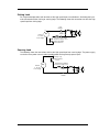
DINP5 (and10)
J4-10, 11
General Purpose input default assigned as ‘No Function’. One of two inputs
that can be assigned as end-travel limit switch inputs. Tie pin 10 or 11 to
common rail for normal operation.
J4-10
DINP5+/
HSINP1+
J4-11
DINP5-/
HSINP1-
221 Ω
2.21 k
The high speed input works directly with 5 volt input, 3.0 to 6.0 volt range,
without the use of a current limiting resistor. To operate the input with voltages
higher than 5 volts, an external current limiting resistor is required in series
with the input.
The input current should be in the range of 9 to 24 mA for proper operation.
The following table lists the recommend current limiting resistors for supply
voltages greater than 5 volts.
:))J
S$DJ
H </
$ 5
!$ 5
! $ 5
35
: /8H J
,,
H,
8< / ,HD
8
# D& T 1
D& T 1
Sinking Load
For single ended operation, both terminals of the high speed input are available on J4 allowing the input
to be connected to either sinking or sourcing logic. The following shows the connections to drive the highspeed input from sinking logic.
J4-10
HSINP1+
+
External
4 - 30 VDC
Power Supply
DC
-
J4-11
HSINP1External Current Limiting
Resistor for supply > 5.0 V
Sinking Logic Output
from Field Device
Sourcing Load
The following shows the connections to drive the high speed input from sourcing logic. The power supply
can be the same power source used to provide power for the general purpose inputs.
+
External
4 - 30 VDC
Power Supply
DC
-
Sourcing Logic
Output from Field
Device
External Current Limiting
Resistor for supply > 5.0 V
J4-10
HSINP1+
J4-11
HSINP1-
36
2.8.2
Base Drive Unit Outputs
General
Purpose
Outputs
DOUT1 and DOUT2 are optically isolated outputs that provide information
about the state of the drive. The outputs are Darlington phototransistors with a
33 volt zener diode wired in parallel to clamp voltage transients.
J4-6,7
DOUT1
FAULT
J4-7
DO UT1+ (FAULT)
J4-8,9
J4-6
DOUT1-
DOUT2
RUN
33V
J4-9
DOUT2+ (RUN)
J4-8
DOUT2-
33V
The following table lists the maximum output rating.
<
- #0
$(
<
-
$
"
!$
;
66
#
CAUTION
#0
$
5
The outputs are not short circuit protected. Configure the application to ensure
the maximum current is not exceeded.
The list below describes the factory defaults for each of the outputs.
&NH& - +
& @ :J
H
&
+ 1& &
+
*&
*
-5 %& - 1& &
+
6 *(
-5
*
%& - *
*"
37
NH& - +
& :8
&
+ 1&
*
%
-5
5 %& - +
-5 %
5
*
& - H& - *& &
+
5
&
&
+
1& &
-
Both the collector and emitter of the phototransistor are on J4, providing the
capability to drive either sinking or sourcing loads.
Sinking Load
+
External
Power Supply
30 VDC MAX
DC
Current Lim iting Resistor
50 m A MAX
-
An opto isolator is being driven in this example. The current through the output
needs to be limited to 50 mA or less, which is accomplished by selecting an
appropriate current limiting resistor. The voltage of the external power source
needs to be 30 VDC or less and can be the same source used to provide
power to the inputs.
Sourcing Load
Clam p
Diode
+
External
Power Supply
30 VDC MAX
Relay
Coil
Current Lim iting Resistor
50 m A MAX
DC
-
In this example, a relay coil is being driven. The current through the coil needs
to be limited to 50 mA or less, which is accomplished by selecting an
appropriate value of current limiting resistor.
The voltage of the external power source needs to be 30 VDC or less and can
be the same source used to provide power to the inputs. A clamp diode must
be added across the coil to clamp the voltage during turn-off.
38
2.8.3
SFD BAT+
NOTE
2.8.4
SFD BAT is not implemented.
DAC Monitors
J4-14
DAC MON1
J4-15
DAC MON2
J4-13, 16, 23,
26
I/O RTN
The DAC Monitors are general-purpose analog monitor points. The output
range is 0.5 to 4.5 volts with a source impedance of 2.9 kΩ, which limits the
short circuit to I/O RTN to 2 mA.
Each DAC Monitor can be mapped by software to one of a number of internal
variables.
I/O RTN is the ground reference for the DAC MON, Analog Command,
Encoder output/inputs, and SFD BAT+. These pins are electrically shorted
together inside the drive.
NOTE
2.8.5
Connect one of the I/O RTN pins to an earth ground point in the
cabinet reserved for single point grounding of all returns (drives
and supplies) to control common mode voltage.
Encoder Outputs
J4-19
CH A OUT/IN
Channels A and B are RS-485 compliant differential outputs.
J4-20
CH A OUT
Channels A and B provide position signals generated from the
feedback device that emulate a quadrature encoder.
J4-21
CH B OUT
The outputs are buffered by 5.0 volt 75LBC170 type RS-422
compatible line drivers. Recommended load current is ±20 mA,
which corresponds to a line-to-line load resistance of 100 Ω. These
outputs are short circuit proof to I/O RTN.
J4-22
CH B OUT
Outputs
The resolution of the Encoder Outputs (number of pulses per motor
revolution), is set by S1 (rotary switch), as follows:
39
2 1:
&
# F
:
4
#
5
-5B
!
!
!
!
!
#
"
#
!
1
User settable non-volatile PPR via the serial port is
more flexible with the following PPR:
128, 512, 1024, 2048, 4096, 8192, 16384, 32768,
125, 500, 1000, 2000, 2500, 5000, 10000, 20000
The maximum output line frequency is 2.5 MHz. Limit line
frequency to below 1.25 MHz, which corresponds to quadrature
count frequency below 5 MHz, for robust operation.
NOTE
J4-17, 18
CH Z OUT
CH Z OUT
2.8.6
The emulated encoder output is only available
when using a high resolution feedback device
such as the SFD feedback to the base unit or
Encoder feedback to the option card. The
emulated encoder outputs have no signals
when there is only base unit 6-step feedback.
The CH Z output is only available when using SFD Feedback. These
two terminals function as a differential, TTL marker pulse. The output
pulse occurs once per motor shaft revolution, starting at feedback
device position = 0. Its width is one line width or two quadrature
encoder widths.
J11
J11 is a five-pin plugable connector to the CAN physical layer and is compliant
with CANOpen and the DeviceNet specification (less color code requirements).
1
40
5
F
F
F
F
F
J11-1
41
V-
'
'!
'
'
'
1
$'
8UJ
&5
8U=
$A
1"
95 .
95
9
1&
#
Return on power supply to CAN physical layer
J11-2 CAN_L
Low level CAN transmission signal
J11-3 Shield
Shield connection point. Tied to chassis ground through 1MΩ resistor in
parallel with 0.01 µF capacitor
J11-4 CAN_H
High level CAN transmission signal
J11-5 V+
Power supply input for CAN physical layer. Rated 11-26 volts dc. Typically
draws 30mA
2.8.7
J12
J12, Option Card General Purpose I/O is a 15-Position High Density D
subminiature male connector.
11
15
6
10
1
5
1
F!'
(,
8) D
F!'
(,
8) A
F!'!
(,
8)#
F!'
A $(
F!'
(,
8)"
F!'
,
E
D H8
F!'
(,
8)
F!' !
( = A
F!'
(,
8)
F!'
( = '
F!'#
D:H '
F!'
( =9A
F!'"
D:H A
F!'
( =9'
F!'
(,
8) '
General Purpose
Inputs DINP 6-9
J12-2, 3, 4, 5 Common
Input Terminal
J12-1
OUT3
J12-6,7
42
1
The general purpose inputs are a bank of four inputs that share a
common terminal, DINP COM, on J12-1. The inputs operate over a
wide input voltage range of ± 4.0 to ± 30 volts. General purpose
inputs are compatible with either sourcing or sinking currents to
provide maximum flexibility for interfacing to field wiring.
This output pair provides a general purpose output configurable by
software to perform one of a variety of functions.
DINP 10: High Speed
Input
J12-8, 9
General Purpose Input with uncommitted opto isolator design. Same
as DINP 5 on Base Unit. Can be tied to common rail (may require a
resistor – see DINP 5 on page 35.
J12 –10
+5 VDC
This terminal provides a 5 VDC output to power an external
command encoder, if necessary. The load current should not exceed
200 mA.
J12-11
I/O RTN
This terminal is the return connection for the 5 VDC supply. An inner
feedback cable shield can be connected to this point. Outer shields
should connect to the shell which is PE.
Shell
Outer shield connection (wired to PE in the drive).
J12-12
CMD CH A+
Channel A and B inputs can be configured to receive position
commands in 1 of 4 modes. The command channels can be placed
in quadrature, step and direction, up/down, or hold modes. Either
differential or single ended inputs can be received. The drive
defaults to differential quadrature mode.
In quadrature mode A leads B is a negative count, which
corresponds to CCW direction looking into the motor shaft.
In step and direction mode, channel B positive commands positive
direction. The step on channel A is counted on the rising edge.
In up/down mode, channel A is counted up on the rising edge and
channel B is decremented on the falling edge.
The maximum line frequency is 2 MHz, the maximum quadrature
count frequency is 8 MHz, and the minimum pulse width is 250 ns.
J12-13
CMD CH AJ12-14
CMD CH B+
J12-15
CMD CH B-
Please see Section 3 for more information regarding the use of the A
and B input channels.
43
2.8.8
J13
F ) +
&
.
1
F
F
F
F
F
F
F
F
'
'!
'
'
'
'#
'"
'
:
$
1
8D
,
E
D
/8
/8
)H
D88/ H
H8
=RA
=R'
F
F
F
F
F
F
F
'
'
'
' !
'
'
'
& !
+
1
)H
H8
A $(
,
E
D H8
/8 = A
/8 = '
/8 =9A
/8 =9'
J13-1
CU
CU (Commutation Phase U) input when using open collector Hall feedback.
This input has a 2.21 k pull-up resistor to 3.3 volts.
J13-2
CV
CV (Commutation Phase V) input when using open collector Hall feedback.
This input has a 2.21 k pull-up resistor to 3.3 volts.
J13-3
CW
CW (Commutation Phase W) input when using open collector Hall feedback.
This input has a 2.21 k pull-up resistor to 3.3 volts.
J13-4
NC
No connect
J13-5
I/O RTN
This terminal is the return connection for the 5 VDC supply. I/O return is
internally connected to PTC return. An inner feedback cable shield can be
connected to this point. Outer shields should connect to the shell which is
PE.
J13-6
CH Z +
J13-7
CH Z -
The CH Z differential input. The minimum pulse width is 250 ns.
J13-8
PTC
The PTC input has a trip point at 2200 .
If a PTC is not used, PTC must be wired to PTC return.
PTC return is internally connected to I/O return
J13-9
PTC RTN
J13 –10
+5 VDC
This terminal provides a 5 VDC output to power an external command
encoder, if necessary. The load current should not exceed 200 mA.
J13-11
I/O RTN
This terminal is the return connection for the 5 VDC supply. I/O return is
internally connected to PTC return. An inner feedback cable shield can be
connected to this point. Outer shields should connect to the shell, which is
PE.
Outer shield connection (wired to PE in the drive).
Shell
44
J13-12
CMD CH A+
J13-13
CMD CH A-
Channel A and B inputs that can be configured to receive differential,
quadrature feedback.
Channel A leads B is a negative count, which corresponds to CCW direction
looking into the motor shaft.
The maximum line frequency is 2 MHz, the maximum quadrature count
frequency is 8 MHz, and the minimum pulse width is 250 ns.
J13-14
CMD CH B+
J13-15
CMD CH B-
2.8.9
Switch Settings
Address Switch S11 & S12 set the MAC ID. The two rotary decimal switches
are used to set the CAN address from 00 to 99.
Baud Rate Switch S13 sets the baud rate. The 4-position piano style dip switch
located at the top of the drive uses switches 1 & 2 to set the baud rate.
Switches 3 and 4 are reserved. The reference of Up is indicated on the label at
S13.
45
& ;&
& ;
( *
:
( *
:
( *
( *
:
:
& ;
& ;.
+
+
+
+
+
+
+
+
$*
2 2
&
$
2
2 "
! .
! .
.
"D
2.8.10 LED2
(2
D@@
5 /(
2
Bicolor LED2. The module/network status LED
-2
2
"
D '5
( +
5
@5
5 5
+
( +
( +
5<
95.
95.
/(
<
-5
@ -5
8
-5
46
5
4
'5
5
( + & -5
-&
( +
-
"
5
+
-5
45 H&
*
+&
-5
5
-5
( +
'5
3 OPERATIONAL NOTES
The S200 Position Node product is simple and intuitive to setup and use.
Chapter 5 is designed to help the user step through the User Interface
Software, S200 OC TOOLS, explaining much of the operation and setup.
Chapter 4 is designed to provide some insight on the application setup for the
product and to discuss some details about the product operation.
3.1 ENCODER INPUT CHANNELS
The S200 CNS Option has the ability to accept pulsed position command input.
The digital command can be set to come from an incremental encoder
(gearing), step and direction controller (pulse and direction), or count up/down.
The inputs for these modes come in the encoder input connections on J12 pins
12-15.
The internal circuitry of these 4 inputs is shown in the following diagram. The
circuits are designed to facilitate a wide range of compatible driver
configurations. They may be tied to differential line drives (as with normal
incremental encoders), Open Collector Outputs (some pulse and direction
controllers), or TTL drivers (wide applications). Driving circuits should be wired
accordingly and must have the DC Commons of the drive and controller tied
together. Failure to tie the DC commons together can cause operation that is
difficult to predict.
Internal Bias
Filters
Customer Inputs
at J12
Differential Line
Receivers
47
3.2 PULSE (STEP) AND DIRECTION
When using pulse and direction the pulses for command come in on the A
channel and the direction on the B channel. The data in Section 3.1 will
facilitate the electrical interface design. Select the ‘Mode of Operation (Drive
Setup Menu) to ‘Electronic Gearing. Set the ‘Command Mode’ (Gearing menu)
to ‘Pulse and Direction. And finally, set the pulses per revolution as the
‘Electronic Gearing Command Ration as revs / pulses. In the below diagram
the system is set up for 1600 pulses per motor revolution.
If no Digital Input is assigned to begin the gearing then the motor will follow
pulses a soon as the drive is enabled. A Digital Input can be assigned to start
the gearing With or Without correction. If one of these is selected then the input
is edge-triggered, meaning that it must go from off-to-on while the drive is
ready and enabled. (More on With and Without Correction in Section 3.3).
3.3 DIGITAL INPUT NOTES
Inputs selected for absolute or relative move must be turned on and maintained
on for the duration of the move. Motion will terminate if the input assertion goes
off during the move.
Only inputs 2 and 3 can be assigned as Registration Move Inputs.
Only Inputs 4 and 5 can be assigned as Direction Limit Inputs.
Using Input 5: Input 5 (DINP5 / HSINP) is an uncommitted high speed opto
isolator available at J4 pins 10 and 11. Simply tie pin 10 to the common rail
(Pin 1) if the common rail is tied to the positive supply an switch pin 11.
Reverse 10 and 11 if the common rail ties to the negative of the supply. Digital
input 5 is rated for 3 to 6 volt operation. If the application requires higher
voltage than simply make the tie to the I/O common rail with a series dropping
resistor.
48
Gearing With and Without Correction: Used for Electronic gear modes to lock
or unlock to / from the master signal. These inputs are edge triggered and must
see an off-to-on transition while the drive is ready and enabled for motion in
order to get motor motion. Selecting Gearing Without Correction causes the
motor to ramp to commanded speed from the master and lock on once the
speed is reached. Gearing With Correction causes the motor to ramp to match
the master speed and overshoots, if required, to catch up to the exact position
of the master at the time that the input was toggled.
Jog Move: This capability exists in both Electronic Gearing and Motion Task
modes. Selecting a Digital Input as a Jog Move pops up an associated velocity
box. Multiple inputs can be programmed for multiple jog velocities. The sign of
the velocity is used to control the direction of the jog.
Fault Reset: The fault reset cannot reset all faults. Please refer to Section 4 for
further information about which faults can be reset.
Registration: Simple registration moves can be performed with the S200
Position Node product. The basic concept needs explanation. Registration is
required, for example, when a plastic web is being fed into cutter knives from a
roll of pre-printed product. For any number of reasons the printing will not be
separated by reliable and repeatable distances. The variation must be
compensated for. The printed material will have a registration mark once-perproduct and the machine will have a detector device capable of detecting this
mark. The S200 is set up with a indexing (Relative Move) motion task whose
feed length is slightly more than the maximum length ever required to feed one
product length into the cutters. Another motion tasking move is defined
Registration Move (with ether latch) with a short distance and triggered by the
registration mark detector. The machine is ready to operate as follows: The
larger Relative Move is executed, the detector triggers the Registration Move
DURING the Relative Move, the motor comes to rest the distance defined by
the Registration Move motion task AFTER the detector fired. If the detector
never trigger the motion comes to stop as defined by the Relative Move
distance. The Registration Move distance should be at least enough to cover
the deceleration distance. Again, only inputs 2 and 3 can be assigned as
Registration Move Inputs.
Relative Move: Relative moves are indexes. Relative Move (w/o Memory)
simply moves the distance expected by the distance stated in the motion task.
Relative Move (W/ Memory) moves the distance expected in the motion task
PLUS and distance remaining from the prior move that was terminated due to
the input assertion going away.
3.4 RAMP CONTROL
The GUI Revision 1.XX presents no option for acceleration / deceleration
control for gearing or jogs. Acceleration control is still possible by using the
variable editor to modify the variables ACCR and DECR for independent
acceleration and deceleration control, respectively.
*** Always be sure that the ACC and DEC variables are set to maximum values
49
when using Motion Tasking or Electronic Gearing Modes. Because values of
ACC and DEC are velocity loop parameters low values will appear to cause
instability and severe overshoot when the product is in a position loop control
mode.
3.5 HOMING
Homing is always required. If the application does not require homing then
simply go into the Profile Setup / Homing tab and select ‘Set Current Position
as Home Position’ and ‘Auto Home Move Upon Enabling the Drive’.
3.6 SAVING DRIVE SETTINGS
It is highly recommended that the properly configured drive have its settings
archived on external media for future reconfiguration. Once the drive is
operating properly the data can be uploaded to the host computer. S200 OC
TOOLS User Interface software is used to accomplish this. The drive must be
‘selected’ on the ‘folder-side’ of S200 OC Tools software. Then simply click the
file menus; File / Save (or Save As), name the file as desired, and direct the file
to the desired directory. The file will default with a ‘.CNS’ extension.
50
3.7 CONFIGURING DRIVE FROM EXISTING FILE
It is often desirable to configure a drive exactly like another one. This is often
the case when reproducing a machine design or changing out a drive on an
existing machine. The configuration of the drive is saved as described in
section above. S200 OC TOOLS User Interface Software is used to configure
the connected drive. The file must first be loaded into S200 OC TOOLS by
using the file menus ‘File / Open’. Locate and select the desired configuration
file. It will be loaded into S200 OC TOOLS ‘folder- side’ as though there was a
second drive talking to the software. The tree structure will show the file as
‘Offline’ and normally as Node1. The full filename, with path, will be under
Node 1. Select this filename with a single click of the left mouse button. The file
can be sent to the connected drive by a right-click of the mouse button and
selecting ‘Download offline Configuration to an Online drive. Save the
configuration to Non Volatile memory.
Save
configuration to Non-Volatile Memory.
Right-Click on Node 1 and select Download Off Line Configuration to On Line
Drive.
51
3.8 UPGRADING FIRMWARE PROCEDURE
Firmware can be downloaded to the drive using the S200 OC TOOLS User
Interface Software. The firmware to download must be accessible by the
computer via local media (hard drive, floppy, CDROM, memory stick, etc.).
The proper procedure for upgrading firmware is as follows:
1.) Archive drive settings as described in Saving Drive Settings, above.
2.) Execute the following firmware upgrade procedure.
3.) Clear memory by ‘Utilities / Reset Variables to Factory Default’
4.) Restore the drive settings using the procedure describes above for
‘Configuring Drive from Existing File
The drive must be selected on the ‘folder-side’ of the S200 OC TOOLS
window. From the menu bar, select ‘Utilities / Download new firmware to drive’.
The drive must be disabled. If the drive is enabled the software will ask you to
disable it. A ‘file locator’ box will pop up allowing you to locate the desired
firmware file to load to the drive. Drive firmware has the extension of ‘.BIN’.
NOTE
A file name that includes the letters ‘CAN’ (ie: S200_CAN_V1_10_00.BIN)
supports CANOpen field bus communication for –CNS product. A filename
that contains the letters ‘DeviceNet’ (ie: S200_DeviceNet_V1_10_00.BIN)
supports DeviceNet filed bus communications for –DNS product.
Open the desired file. S200 OC TOOLS
will direct you to ‘set’ DIP Switch S13-4
(located on the top of the product) to a
position at the top of the product. Set
this switch. The photo to the right shows
S13-4 in the proper position to load
firmware.
Some Versions of S200 OC TOOLS mistakenly refer to switch S13 as S3.
NOTE
52
A progress window will come up to indicate the firmware load is taking place.
Upon completion S200 OC TOOLS will put up a status box asking you to turn
S13 back to it’s original (UP) position and cycle power on the drive BEFORE
clicking the ‘OK’ box. S200 OC TOOLS will then begin to operate normally with
a data refresh.
53
4 FAULTS AND ERRORS
The S200 Position Node product has internal fault and error monitoring
systems. Constructed of a base-unit drive and a position controller board the
product actually has two monitoring systems and three annunciation systems.
The Base Unit is the drive-portion of the product and is an S200 Series AC
Motor Drive with a single green status LED that signals status of the base unit.
The position controller card has a seven segment status display used to
indicate faults. Finally, the CAN bus firmware has access to a separate MNS
bi-color LED to signal bus status. This section provides information about these
3 status indicators, the faults they represent, the conditions that can cause the
faults, and how to recover from the faults.
Faults can occur with primary detection by the drive base-unit. These faults are
called ‘b-faults’. (‘b’ Is for Base Unit’). Faults that are primarily detected by the
position controller card are called ‘F-faults’ (‘F’ for fault’) or ‘o-faults’ (letter O).
Base unit errors are detected by the position controller card and become F20
faults be definition. The position controller card annunciates these with an ‘F20’
in the seven segment display followed by the ‘b-code’ (base unit) fault.
The user interface software, S200 OC Tools, displays drive status information
on the Status Menu real-time. The status block will indicate both a Position
Card Fault and the Base-unit fault, if applicable.
4.1 CAN BUS STATUS INDICATOR
The CAN bus status indicator’s function is largely guided by the rules and
definitions of the CAN bus interface standards. Different software can provide
different functions. Details about this status indicator are located in the
appropriate reference manuals for the can bus interface. If the CAN bus portion
of this product is not used (not connected) then a word about this LED is
justified here. S200 Position Node products with the –CNS suffix will normally
have this indicator a solid green with no CAN Bus connected and the drive
enabled but will flash green at approximately once per second if the drive is
disabled. S200 products with the –DNS suffix will normally have this LED a
solid red with no CAN Bus connected.
4.2 NORMAL INDICATOR OPERATION
The remaining two indicators are easy to understand in normal operation.
The green status LED on the Base Unit will flash at a constant (2 times per
second) rate if the drive is disabled and there is no base-unit fault condition.
The green status LED will remain illuminated if the drive is enabled and there is
no base-unit fault condition. At anytime a base-unit fault condition exists this
LED will flash a code. The code is signaled by a 2 second LED off-time
followed by a series of flashes. Counting the number of flashes indicates the
numerical fault code.
The 7-segment display is under control of the position loop controller. The
decimal point is always on and has no meaning. The display will flash a series
of numbers on power-up indicating the drive model number. The display then
goes into normal operation. Power-up indicator may flash b-s-2-0-3-6 indicating
that the base unit drive model is ‘S2036(0 implied)’ model. Under normal
operation the 7-segment display simply displays a ‘d’ for disabled without faults
or an ‘E’ for enabled without faults. Anytime that a fault condition is detected by
the position controller card the display is likely to flash a code sequence.
54
4.3 CLEARING FAULT CONDITIONS
There may be several ways to clear any given fault. The tables located below
will provide more information directed at explaining the recovery method for a
particular fault. There are a couple of guidelines that should be noted. To clear
a fault the condition that caused the fault must no longer exist. (i.e.: short circuit
of motor leads has be cleared). All faults can be reset with a power cycle of the
logic control power. All faults can be cleared by the GUI executing a Coldstart
procedure. The product can be configured to have an input serve a ‘Clear
Fault’ input. The Clear Fault input is limited as to what faults it can actually
reset. Details of the Clear Fault input are listed in the below tables.
4.4 CONDITIONAL SETTINGS
It is possible that the actions of some ‘less fatal’ fault conditions have
conditional settings configurable within the User Interface Software. The
following tables do not explain conditional occurrences rather only the default
actions.
4.5 S200 POSITION CONTROLLER FAULTS
Table 4.1 lists the S200 Position Controller faults, the action that the drive will
take upon sensing the fault condition, and the fault recovery methods allowed.
Some of these faults can have multiple source reasons.
Display
Error
Code
Description of Fault
@ 7 @"
@
Drive Action
+
D+
-
*4
%
( +
&&
@ 7@
@
+
,
X
3 - +5
- 3
8 NH&
,
!H -5 * 5
5
@# 7 @
D
@!
1
E9
%<:,
45
5 * & 5 @ -5 -%
@ -5
(
5E
/ 5% 5
V
( +
W9- %
)*
%<:,
45
:
V' -5W
V' -5W
+
+
*& &*
55
( +
5 * & 5 @ -5 -%
@ -5
(
5E
/ 5% 5
V
( +
W9- %
)*
+
@!
@! 7 @!
@!
@!#
Reset Method
J
+
* &
54
-5
N1
0
*5
5 - @!
&
( +
-5
+
5 *&
8
5 @ -5 -%
(
5E
/ 5% 5
V
( +
W9- %
)*
5 @ -5 -%
(
5E
/ 5% 5
%<:,
45
%<:,
Display
Error
Code
Description of Fault
Drive Action
Reset Method
V
( +
)*
@!" ' @
@!
%
45
+
4
*
( +
5 * & )*
45
@ -5
& -5
( +
5 * & 5 @ -5 -%
@ -5
(
5E
/ 5% 5
V
( +
W9- %
)*
5
4
H&
,Y
-
5
5
4 5
5
+
-
*&
4
+
)H
5
!7
!
W9-
4
G-
( +
')
-
*& .
%<:,
45
+
8 *@ *
H&
& &&
+
4 -5
& -5
4 5
+
5
&
+
( +
:
( +
4 & .-
5* & ) *
45%
@ -5
( -5)
5
( +
5
5*
4
5* & ( + V
@
4
@ -5
( -5 & +
+ -5
4
+
* 5
%
5
5*
4 5
Table 4.1: Position Controller Fault List
4.6 EXTENDED FAULT INFORMATION
As stated in the above section the Position Controller fault may come from
different sources. A Status word can be viewed using the GUI Utilities/Edit
Variables On Line feature. The below table gives the meaning of each bit in the
Status word.
Fault Code
Status
Bit
16
1
SFD UART parity error
The SFD UART received a parity error.
SFD UART
Error
2
SFD UART overrun error
3
SFD UART framing error
The SFD UART received a second transfer without
reading the first.
SFD UART stop bit was not the correct polarity.
17
4
SFD Frame timeout
SFD Comm
Error
5
SFD transfer incomplete
56
Extended fault
Definition
Indicates that more then 89.6 uSecs has elapsed
since last frame was received.
Indicates that a transfer started but did not
complete in 18.4 microseconds.
6
SFD CRC error(s)
7
SFD Motor Data timeout
3
8
Drive over temperature
The drive has an over temperature fault
Drive
Over/Under
9
9
Drive under temperature
The drive has an under temperature fault
10
Drive short circuit
l-n Short
11
Drive output over current
One or both the current sensor A/D has been in
positive current saturation for longer then 10
microseconds.
Drive over current
18
12
Option card read timeout
OC response time out
Option Card
Watch Dog
Time out
19
13
Option card watchdog time
out
OC Watchdog timer timed out
14
Step size overflow
Size of revs per step greater than 255 revs per step.
PosErr Too
Large
15
PosErr overflow
Position loop position error greater then +/-128
revs.
20
16
Option Card Feedback Fault
Fault with the option card encoder feedback
Motor l-l or
In SFD Span mode, this indicates that there was
more then one CRC error over 256 transfers. If not
in SFD Span mode, any CRC error will fault.
SFD configuration did not complete within 49.2
milliseconds.
OC Fault
Table 4.2: Extended Status Word Fault Code Information
57
4.7 S200 BASE UNIT FAULTS (B-FAULTS)
As previously stated the base unit Status LED will flash a code if the drive is in
a faulted condition. The following table explains the fault code.
Flash Count
Status
Resulting Drive Action
Reset Method
1
No Fault drive disabled
Normal Operation
2
Motor Over Temp sensor has
tripped
Drive Disabled with fault
Clear Fault input, Disable/Enable, Coldstart, GUI
‘Drive Reset’ Button, or Cycle Power
3
Drive Over/Under Temp
Drive Disabled with fault
Clear Fault input, Disable/Enable, Coldstart, GUI
‘Drive Reset’ Button, or Cycle Power
4
Drive I*t Too High; Exceeded
RMS ratings of the drive.
Drive Disabled with fault
Clear Fault input, Disable/Enable, Coldstart, GUI
‘Drive Reset’ Button, or Cycle Power
5
Motor I*I*t Too High; Exceeded
RMS ratings of the motor.
Drive Disabled with fault
Clear Fault input, Disable/Enable, Coldstart, GUI
‘Drive Reset’ Button, or Cycle Power
6
Reserved
7
Bus Over Voltage; Mains highline or excessive regeneration.
Drive Disabled with fault
Clear Fault input, Disable/Enable, Coldstart, GUI
‘Drive Reset’ Button, or Cycle Power
8
Bus Under Voltage
Drive Disabled with fault
Clear Fault input, Disable/Enable, Coldstart, GUI
‘Drive Reset’ Button, or Cycle Power
9
Motor l-l or l-n Short
Drive Disabled with fault
Clear Fault input, Disable/Enable, Coldstart, GUI
‘Drive Reset’ Button, or Cycle Power
10
Output Over Current
Drive Disabled with fault
Clear Fault input, Disable/Enable, Coldstart, GUI
‘Drive Reset’ Button, or Cycle Power
11
Hall Fault
Drive Disabled with fault
Clear Fault input, Disable/Enable, Coldstart, GUI
‘Drive Reset’ Button, or Cycle Power
12
SFD Configuration Error
Drive Disabled with fault
Clear Fault input, Disable/Enable, Coldstart, GUI
‘Drive Reset’ Button, or Cycle Power
13
SFD Short
Drive Disabled with fault
Clear Fault input, Disable/Enable, Coldstart, GUI
‘Drive Reset’ Button, or Cycle Power
14
SFD Motor Data Error
Drive Disabled with fault
Clear Fault input, Disable/Enable, Coldstart, GUI
‘Drive Reset’ Button, or Cycle Power
15
SFD Sensor Failure
Drive Disabled with fault
Clear Fault input, Disable/Enable, Coldstart, GUI
‘Drive Reset’ Button, or Cycle Power
16
SFD UART Error
Drive Disabled with fault
Clear Fault input, Disable/Enable, Coldstart, GUI
‘Drive Reset’ Button, or Cycle Power
17
SFD Comm Error
Drive Disabled with fault
Clear Fault input, Disable/Enable, Coldstart, GUI
‘Drive Reset’ Button, or Cycle Power
18
Option Card Watch Dog Time
out
Drive Disabled with fault
Clear Fault input, Disable/Enable, Coldstart, GUI
‘Drive Reset’ Button, or Cycle Power
19
PosErr Too Large
Drive Disabled with fault
Clear Fault input, Disable/Enable, Coldstart, GUI
‘Drive Reset’ Button, or Cycle Power
20
Table 4.3: Base Unit Fault Table
58
4.8 SYSTEM WARNINGS
Warnings are like faults in that they can terminate motion. In most cases they
will not cause the
Warning Code Description
N01
Reserved
N02
Reserved
N03
Position Error Warning
N04
Watchdog Limit Reached
N05
Reserved
N06
Software Limit Switch 1 Active
N07
Software Limit Switch 2 Active
N08
Invalid Motion Task Has Been Initiated
N09
Home Reference Point Not Set
n10
Positive Hardware Limit Switch Activated
n11
Negative Hardware Limit Switch Activated
n12
Reserved
n13
Reserved
n14
Reserved
n15
Invalid Velocity Current Table Entry Error (INXMODE=35)
n16…n31
n32
Reserved
Current Drive Firmware Version is a Beta Release
drive to disable. Warnings can be reset using Clear Fault input or GUI Drive
Reset input.
Table 4.4: Warning Codes
59
5 SETUP SOFTWARE
The User Interface software package is called S200 OC TOOLS. Begin by installing the
S200OCTools software. Follow the prompts. Once the software is installed, connect the
computer’s RS232 port to the wired and powered drive and motor. Double-click on the
S200OCTools icon to open the software. The software, when opened for the first time,
will automatically invoke a startup wizard that will take the user through a guided setup
tour meant to bring attention to some of the basic setup requirements. The wizard can be
defeated by checking the ‘Do not show this wizard again’ box. It can be invoked anytime
using the ‘Utilities / Full Setup Configuration Utility’ menu bar. While there are many
options this section of the manual will guide the reader through some basic setup
parameters. After going through this section the software should be easy to understand
and the drive ready to run. The user should be comfortable enough to proceed without
further guidance.
,
NOTE
&
4&
'+ 5 5
4- 5& 8$ $/ & :5
- & 8$ + -
&
3 -
+
&
+
& -&
The left-side of the screen is the ‘Folder-side’. The folder side shows what drives is
connected and any open backup files. Some until the drive is selected by clicking on the
appropriate folder.
60
Open Existing Backup File
Open New Backup File
Enable
Communication Wizard
Open Oscilloscope
Disable
COLDSTART
Set Home
Stop Motion
Save to Nonvolatile Mem
Close Backup File
Save Backup File
Jog CCW
Jog CW
Jog Speed
Drive Data File View
Backup File View
Drive Model
Fault Status
Operational Mode
61
Drive Enable Status
open an existing drive back up file to work offline.
Once
invoked,
S200 OC
TOOLS will
need to
retrieve the
data from the
drive. If no
drive is
connected
S200
OCTOOLS
cannot be
navigated
unless you
Once the
data upload
is complete,
the wizard
screen will
appear. (Or
can be
invoked
using
‘Utilities /
Full Setup
Configuration Utility’ The wizard will guide you through the necessarily steps to
complete the drive configuration.
62
Equipped’ AKM-Series motor.
The first
step is to
confirm that
the drive is
configured
for the
motor being
used. This
information
is
automaticall
y gathered
from a
system
using an
‘SFD-
This system is using an AKM21C motor with SFD. Enter the load-to-motor
inertia ratio. You can set the Inertia Ratio or select a different motor.
The user
can elect
to set the
drive up to
use
customized position units. Set the desired mechanical user units by clicking on
the Mechanical tab. Specify how many units per motor revolution. Here we
have the drive set up for 65536 counts per motor revolution.
63
The Drive
Setup tab
is where
the
drive’s
mode of
operation
is set for
Digital
Velocity,
Electronic
Gearing
or Motion
tasks.
This
example
has
selected
Motion
Tasks that will allow indexing and absolute positioning. Additional boxes and
tabs for gearing, tuning, faults, and thresholds and other system limits should
be explored.
See Chapter 7 for more details on Digital Velocity Mode.
The I/O
Setup
tabs
provide
an easy
and
convenient way to link inputs and outputs to execute moves and report status.
Not all inputs can serve all functions. Pull down the menus and browse around.
Set up inputs for both the base unit and the option card functions.
Note: When inputs are changed a ColdStart is required.
64
The Profile
Setup menu
allows you
to set
homing and
motion
tasks. This
screen
shows a
handy
method to
set home
when the
system
doesn’t
really need
to have a
home
reference.
Homing always has to be done. Shown above is a method to home without
ever having to know that you homed. You can not change motion task 0. It
follows then that executing a BCD code of 0 executes a homing routine.
For systems requiring homing to a switch there are options to simply find the
switch and stop or to find the switch, stop, and move back to home.
information on inputs and move types.
Set up
motion
tasks as
required.
Motion task
0 will
always be a
homing
routine. The
task
number is
the binary
code if BCD
select is
used. See
section 4
about more
End of Task condition can be a blended move. A
Blended move concatenates two moves together without having to go to zero
speed to begin the second move. The actual index distance will be the sum of
the blended move distances. Distance move is based on actual motor position,
not commanded motor position.
65
Next Motion Task can set the motion task that will be blended to the present
move (if blended move is selected) or can be used to automatically start
another move without the need for an additional input signal; the ‘next motion
task’ will be executed upon completion of the present move. A ‘Next Motion
Task’ of ‘none’ places a ‘0’ in the table but does not mean to execute a home
(motion task 0); it is interpreted as ‘do nothing’. An In-Position output will not
come on until all moves are complete.
A Dwell Time can be added which occurs at the end of the move. The dwell
time’s purpose is to add a delay to moves linked with Next Motion Task (not
blended moves). If there is no Next Motion Task then the dwell timer performs
no function.
The check box ‘Executes after home’ is simply a means of making an
equivalent function of ‘Next Motion Task’ after ‘Homing’ available. (There is no
other way to do that since you can not directly edit Motion Task 0).
Coldstart is a process whereby the firmware generates custom internal code
(compiles) for extremely fast execution. It is good practice to hit the Coldstart
button after changing motion tasks and I/O assignments. Without it you may
get results that indicate that your changes did not take affect.
Move types
include:
Relative
move with
Memory:
When
indexing
(relative
moves) an
early
termination of
prior moves
is
remembered.
Choosing this
Move Type
calculates the
next move
distance as the sum of the entered move distance PLUS the distance that did
not get made in earlier moves due to early termination of the index.
Relative Move Without Memory: When indexing (relative moves) this input
cause the index distance in the associated motion task to be executed. There
is no reference to earlier lost motion.
Absolute Move: Moves to an absolute position relative to the home location.
Relative Registration Moves: Explained in Chapter 4
.
66
For
demonstration
purposes; the
system shown
on the left will
index one
motor turn
(User Units
are set to
65536 counts
per rev) each time input 6 is turned on. Input 7 will cause the motor to turn back
to its original locations.
Always remember to hit the Save to Non-volatile memory to save your
configuration. (Button circled in Red).
67
6 SYSTEM TOOLS
6.1 STATUS SCREEN
The Status
screen can be
helpful to
understand
system
operation. Drive
Status should
read ‘OK’. If not
Drive OK
then a
Indicator LED
meaningful fault
code will be
shown.
General
information
about drive size
and firmware
version is
shown.
Energizing a
drive input causes the green ‘Virtual LED’ to illuminate. If an output is on then it’s
Virtual LED will illuminate.
Position and velocity information can be monitored.
Jog CounterClockwise
Jog
Clockwise
68
If the system
is safe to
accept motion
then the
motor can be
jogged from
the status
screen.
6.2 COMMUNICATION WIZARD
A communications wizard can be found
under the Utilities menu. This allows you
to select the RS232 communications port
for the computer being used and allows a
simple test of communications. Baud rate
is always 38.4k Baud. Other port
parameters are automatically set by
S200 OC TOOLS.
6.3 VARIABLE EDITOR
Although the
variables available
in the S200 Position
Node product are
not well documented
there may be a
reason that a user
wants to view or
change them. The
Utilities/Edit
Variables On-Line
tool brings up this
box which can be
used to monitor or
modify up to 8
variables at a time.
69
6.4 DIGITAL OSCILLOSCOPE
Up to 4 channels of data can
be recorded simultaneously.
Set the channels for the
desired data, the sample rate
for an appropriate buffer
size, and a trigger level
suitable for the capture.
Press Start. The scope data
plots will be presented after
the trigger occurs. It is
important to note that each
plot has an independent
vertical axis scalar.
plot to the left has AVGTIME set to 64.
A variable called AVGTIME
can be changed using the
above-mentioned variable
editor. AVGTIME will allow
averaging of data to make it
more presentable form. The
The plot to the left has
AVGTIME set to 0. The
effect of having AVGTIME
set to a value is smoothing
but setting AVGTIME to a
large number can
sometimes prevent the
data from showing proper
detail and relationship – as
any low pass filter would.
AVGTIME is the number of
reads summed in the
average calculation.
70
6.5 CONFIGURATION SUMMARY SCREEN
The configuration
Summary screen allows the
user to see all the drive
settings in one location
without having to navigate
through each possible GUI
menu.
71
7
SERIAL COMMUNICATIONS AND
MODBUS RTU
7.1 GENERAL INFORMATION
The serial communications port on the S200 Position Node product uses an RS232
physical layer and communicates using a protocol known as Modbus RTU. The Modbus
protocol implementation of the S200 -CNS/ -DNS options is based on the on the
documents:
MODBUS over Serial Line V1.0
MODBUS Application Protocol Specification V1.1
Details of the protocol itself are not covered in this document. Both aforementioned
documents can be obtained at www.modbus.org.
This documents assumes that the user is knowledgeable about the information contained
in those documents and has some level of knowledge about serial communications, in
general. It is not the intent of this document to provide that basic information.
Section 7.6 will reiterate this but the Modbus strategy is kept simple: always 2-16 bit
word transfers (Defined by most interfaces as the ‘swapped mode’) using either integer or
floating point data types. The tables at the end of this section identify the data types for
each variable.
7.2 ABBREVIATIONS
Abbreviation
Description
UA
Unit Address
The unit address of the option card
configured through the rotary switches; S11
and S12.
FC
ModBus Function Code (Defined by
standard)
CRC
16bit Cyclic Redundancy Check Value
72
7.3 RS232 SERIAL PORT CONFIGURATION
Baud rate:
Data bit:
Stop bit:
Parity:
38400
8
1
Odd
7.4 EXCEPTION MESSAGES
The Modbus protocol defines exceptions (error identification methods). The S200
implements exceptions according to the requirements and defines additional exception
codes. The following table lists all proprietary codes.
Exception
Code
73
Description
10
Invalid Quantity
11
Invalid register address
12
Invalid package number
13
Command is in execution
14
Unknown command ID
15
Command requires disabled drive
16
Invalid Motion Task number
17
Next Motion Task number is invalid
18
Enable Drive rejected
19
Writing data to FLASH failed
20
Parameter is not of type String
21
Scope: Internal error
22
Scope: Invalid Signal Name
23
Scope: Invalid Signal Size
24
Scope: Invalid record data
25
Step: Invalid Step length
26
Step: Velocity 1 for Step is out of
range
27
Step: Velocity 2 for Step is out of
range
28
Step: Velocity Mode is required
29
Memory Allocation Error
30
Internal error
31
Scope: No lookup table available
Exception
Code
Description
32
Scope: Wrong lookup number
33
String length is invalid
7.5 COMMUNICATION STRATEGY
The S200 Position Node product has a lot of functionality. Decisions must be made as to
how much of this should be implemented at the customer’s end of the communication
network. There may be some limitations. Most limitations can be overcome. Limitations
include;
1.) The S200 Position Node communications is based on RS232 physical layer. This
is to say that multidrop communications is not directly supported by the S200
Position Node hardware. This can be overcome with external RS485-to-RS232
converters.
2.) Changing the function of an discrete input on the S200 Position Node (Inx)
requires a Coldstart function. A Coldstart function can be a little complex on the
Modbus scheme as it requires a Manufacture-Specific Function Code and a statuscheck loop. It may be better to define the input functions in the GUI and
associated drive setup configuration file and leave it static.
3.) Certain functions require Manufacturer-Specific Function Codes to execute. This
is normally not a problem unless you have a pre-manufactured terminal that has
limited communications configuration capability that can not easily support
manufacture-specific function codes. For example; Modifications to Motion Task
table requires a customized Function Code.
4.) Setup of motor parameters over Modbus is not supported. Please use the GUI
software and/or configuration backup files for setting these parameters.
5.) Variables regarding the digital inputs can be misleading. In documentation and
wiring diagrams we label the inputs DINP1 through DINP 10. In the Modbus
protocol we call these Enable through IN9. Enable relates to DINP1, IN1 related
to DINP2, IN2 relates to DINP3, etc.
6.) When using third-party Modbus software such as Modbus Poll the data types may
have to be set to Long Inverse or Float Inverse to make the data easily readable.
74
7.6 MODBUS FUNCTIONS
To simplify the communications the S200 Position Node is set up with almost all data
defined as 32bit values comprised of two 16-bit registers. The data type of any one of
these register sets can be defined as Long, Text, or Float data types. With a few
exceptions, all communications to the S200 Position Node card will be Read Holding
Registers (FC=03) or Write Multiple Registers (FC = 16).
The register address of each parameter is aligned to an even register address values.
Variable address in the GUI software is set up as 32-bit address space and is called the
PDID (using variable browser utility). The Modbus registers, being 16 bit address space,
are addressed at 2 * PDID value. Please see address table at the end of this chapter.
The first register (even address) is the high word of the 32 bit value, the second register
(odd address) the low word.
Important: Although data transfer should be done using FC 16 (Write Multiple
Registers, quantity 2) the Position Node does support write of a single register:
1. To synchronize the write access when using single register access both registers
of a parameter need to be written to starting with the high word (even address). If
the low word is accessed first, an error exception occurs.
2. The firmware supports only a block read/write access of up to 2 registers. Both
registers must belong to the same parameter.
Each parameter has a set of attributes like minimum value, maximum value, default
value, read only, data type, etc., which can be uploaded from the option card. See tables
at the end of this section for details.
7.6.1
Reading Variables
To read a variable use the Modbus Function ‘Read Holding Registers’. As found in the
Modbus documents the serial communication model for a variable read is presented as
follows:
UA=x FC =
x
3
Address
(16bit)
Number of registers
(16bit)
CRC
Where:
UA is the unit address of the drive as set by rotary switches S11 and S12.
FC is the Read Multiple Holding Register Function Code (03).
Address is the variable register address (even number).
Number of registers to read should be set to 2.
75
As defined by Modbus, the S200 Position Node product will respond with the value set in
those registers:
UA=xx
FC=3
data length
data
CRC
Where:
UA is the unit address echoed back.
FC is the function code echoed back (03)
Data length will be 2 (Data count)
Data will be the 32 bit value of the variable read. Variable type may be Long or
Float.
7.6.2
Writing Variables
To write variables use the Modbus Function ‘Write Multiple Registers’. As found in the
Modbus documents the serial communications model for a variable write is presented as
follows:
UA
FC = 16 Address(16bit)
Register count (16bit)
Length Data CRC
Where:
UA is the unit address of the drive as set by rotary switches S11 and S12.
FC is the Write Multiple Registers function code (16 decimal = 0x10)
Register Count - Data length will be 2 (Data count)
Data will be the 32 bit value of the variable read. Variable type may be Long or
Float
As defined by Modbus, the S200 Position Node product will respond with the value set in
those registers:
UA FC = 16 Address(16bit) Number of Registers(16bit)
CRC
Where:
UA is the unit address echoed back.
FC is the function code echoed back (16d / 0x10).
Address is the address of the registers written echoed back.
Number of registers (written) echoed back - will be 2 (Data count)
76
7.6.3
Example: Read the ACC parameter
The following example on how to read the value of the ACC registers is
presented. The guidelines in the example are as follows:
Unit address is 2 (S11 = 2, S12 = 0)
The actual value of ACC in the drive is 10,000 decimal / 0x2710
From the table, the address of ACC is 2 and the data type is long.
As defined in above text, all variables are 32 bit constructed with 2 contiguous 16
bit registers.
Transmit the request to read the value of ACC:
0x02 0x03 0x00 0x02 0x00 0x02 CRC low
CRC hi
Response from the S200 Position Node:
0x02 0x03 0x04 0x00 0x00
0x27
0x10
CRC low CRC hi
An actual communications monitor report for this communication transaction
looks like the following:
7.6.4
Example: Write the ACC parameter
Assume we wish to change the value of ACC to 20,000 in the above example:
Transmit the request to write:
0x02 0x10 0x00 0x02 0x00 0x02 0x04 0x00 0x00 0x4E 0x20 CRC low CRC high
Response from the S200 Position Node:
0x02 0x10 0x00 0x02 0x00 0x02 CRC low
77
CRC high
An actual communications monitor report for this communication transaction looks
like the following:
7.6.5
Example: Change Speeds in Digital Velocity Mode
The S200 Position Node can be set up to operate in Digital Velocity Mode. Velocity is
controlled by the ‘J’ parameter = PDID 1934 = Modbus Address 3868. The following
communication traffic window changes the speed to 563 RPM:
Note that this data traffic representation is sending the speed, 563, as a floating point data
type.
78
7.7 MANUFACTURER SPECIFIC FUNCTION CODES
7.7.1
Command functions
Modbus allows a block of function codes to be assigned by the manufacturer. The S200
Position Node product has chosen to implement the following function codes.
7.7.2
Command Execution: FC 65
The following model is the general form of the commands. Function Code 65 and the
command ID request triggers the execution of a command function (see table below).
Transmit the command to the S200 Position Node:
UA=xx
FC=65 command id
CRC
Response Received from the S200 Position Node:
UA=xx
FC=65 command id CRC
The defined commands are:
Command
Id
Save Parameters Non-volatile memory
1
Restore Parameters from Non-Volatile Memory
2
Set all parameter to factory default settings
3
Enable Drive
12
Disable Drive
13
Coldstart Drive (Reset)
14
Reset Faults and Warnings
15
79
7.7.3
Command execution status
Used to determine the status of a formerly transmitted command execution request, i.e.
the command save parameters non-volatile takes some time to be performed. This request
allows to check if the command is finished.
UA
UA
FC=67
CRC
FC=6 Status(16bit) CRC
7
Status
Id
Idle (read to execute command)
0
Busy (command execution in progress)
1
Success
2
Failed (last command execution failed)
3
7.7.4
Drive Status
This command requests a predefined list of status variables to be sent in one message
block. Each variable can be requested separately through 'Read Register'. Hence status
information is likely to be requested very often, this command saves communication
overhead.
UA
FC = 65
Command Id = 7
UA FC = 65 Command Id = 7
CRC
Length(16bit) Variables CRC
The response message contains the following variables. Each variable is a 32bit integer.
Variable
Name
PFB
80
Description
Position Feedback
Variable
Name
7.7.5
Description
POS
Position Command
V
Velocity Feedback
VCMD
Velocity Command
ICMD
Torque Command
STATUS
Software Status Word
STAT
Second Software Status
Word
Panic
Panic Flags word
errCode
Error Code Flags
INPUT
State of digital inputs
OUTPUT
State of digital outputs
buErrCode
Base Unit Error Code Flags
ocErrCode
Option Card Error Code
Flags
Warning
Warning Flags
Set Motion Task
UA FC = 65 Id = 8 Block Length(16bit)
MotionTaskStructure
CRC
Motion Task Structure:
typedef struct {
unsigned short nr;
//! motion task number
sInt64 targetPosition;
//!< O_P
int velocity;
//!< O_V
int V_soll;
//!< command/max velocity in counts
int accel;
//!< O_ACC
int decel;
//!< O_DEC
unsigned int controlWord; //!< O_C
int res1;
//!< reserved
short tabNumber;
//!< O_TAB
short res4;
//!< reserved
unsigned short nextTask; //!< O_FN
unsigned short delay;
//!< O_FT
} PACKED tsMotionTask;
UA
81
FC = 65
CID = 8
CRC
Clear Motion Task
UA FC = 65
Id = 10
UA FC = 65 Id = 10
Motion Task Number (16bit)
CRC
Minimum Wait Time (16bit)
CRC
The Minimum Wait Time is the time the master must wait at least before sending the next
request. Motion Tasks are stored in the program FLASH. During write access the FLASH
cannot be accessed and communication is down until the FLASH is back into normal
operation.
7.7.6
Clear All Motion Tasks
UA FC = 65 Id = 11 CRC
UA FC = 65 Id = 10 Minimum Wait Time (16bit)
CRC
The Minimum Wait Time is the time the master must wait at least before sending the next
request. Motion Tasks are stored in the program FLASH. During write access the FLASH
cannot be accessed for program execution and communication is down until the FLASH
is back into normal operation.
7.8 MOBUS ADDRESS AND FUNCTION TABLES
The following tables contain the required data for implementing Modbus commands. The
advanced user may determine that functions other than these will show up in the GUI
Variable browser. The functions listed here are the only functions supported by the
Modbus communication.
82
Appendix C: Application Notes
07/06
Danaher Motion
PDID
Index
Modbus
Address
Name
1
2
2
4
ACC
ACCR
Long
Long
R/W
R/W
300000
300000
1
1
12000000 RPM/S
12000000 RPM/S
3
4
6
8
ACTFAULT
ACTIVE
Long
Long
R/W
RO
1
-1
0
0
1 See List
0 On/Off
6
34
12
68
AENA
DEC
Long
Long
R/W
R/W
1
300000
0
1
1 On/Off
12000000 RPM/S
Software Auto Enable: 1 Normal, 0 Disable at power
up
Velocity Loop Deceleration Limit
36
37
72
74
DECR
DECSTOP
Long
Long
R/W
R/W
300000
300000
1
1
12000000 RPM/S
12000000 RPM/S
Jog and Homing Deceleration Limits
Priority Stop Deceleration Rate (See Vel0)
41
44
82
88
DIPEAK
DREF
Float
Long
RO
R/W
0
0
4294968
0
4294968 Amps
34 CW/CCW
45
90
DRVSTAT
Long
RO
0
-1
-1 Bit Coded
50
100
ENCIN
Long
R/W
1024
16
62
63
124
126
GEARI
GEARMODE
Long
Long
R/W
R/W
1024
0
-2.15E+09
0
64
88
128
176
GEARO
I
Long
Float
R/W
RO
1
0
97
98
194
196
IN1
Long
Long
RO
R/W
100
101
200
202
Long
Long
103
104
206
208
106
107
212
214
109
110
122
83
Data
Default
Type Rights Value
Min Value Max Value Units
32767 LPR
Comments
Velocity Loop Acceleration Limits
Jog and Homing Acceleration Limits
What to do upon fault
Returns 1 if drive active, else 0
Returns Drive's Peak Current (RMS) Rating
Set Homing Direction
Return Drive Status Bit Word
Encoder Resolution for Encoder Feedback Systems
Gearing mode: Sets GEARI pulses within GEARO
motor turns
2.147E+09 Counts
9 See List
Sets Electronic Gearing Mode
0
4294968
2.147E+09 Counts
4294968 Amps
Gearing mode: Sets GEARI pulses within GEARO
motor turns
Returns actual motor current
0
0
0 On/Off
List
Returns the state of DINP2
Sets the function of DINP2
RO
R/W
0
17
0
0
0 On/Off
90 List
Returns the state of DINP3
Sets function of DINP3
Long
Long
RO
R/W
0
9
0
0
0 On/Off
90 List
Returns the state of DINP4
Sets function of DINP4
IN4MODE
Long
Long
RO
R/W
0
0
0
0
0 On/Off
90 List
Returns the state of DINP5
Sets function of DINP5
218
INPOS
Long
RO
0
0
0 On/Off
220
244
IPEAK
LATCH2P32
Float
Long
R/W
RO
2.25
0
0
-1
4.5 Amps
-1 Counts
IN1MODE
IN2
IN2MODE
IN3
IN3MODE
IN4
Returns the state of the IN Position bit of the Status
Register
Allows the user to lower the peak application current
Returns Positive edge latch position
S200 Position Node with CANOpen/ DeviceNet
Serial Communications and Modbus RTU
07/06
Danaher Motion
PDID
Index
Modbus
Address
123
140
246
280
LATCH2N32
VLIM
Long
Long
RO
R/W
0
10000
-1
0
141
282
MH
Long
WO
0
-128
127 Start
145
163
290
326
MJOG
MSPEED
Long
Long
WO
R/W
0
10000
-128
0
127 Start
16000 RPM
174
177
348
354
O1
O2
Long
Long
RO
RO
0
0
0
0
1 On/Off
1 On/Off
180
197
360
394
OPMODE
PE
Long
Long
R/W
RO
8
0
0
-1
8 List
-1 Counts
198
199
396
398
PEINPOS
PEMAX
Long
Long
R/W
R/W
4000
262144
0
-2.15E+09
2.147E+09 Counts
2.147E+09 Counts
200
400
PFB
Long
RO
-1
-1
-1 Counts
Returns the Position Feedback value
201
402
PFB0
Long
RO
-1
-1
-1 Counts
Returns the position counter of the external encoder
202
404
PGEARI
Long
R/W
65536
1
2.147E+09 NA
203
406
PGEARO
Long
R/W
1
1
32768 NA
210
420
PRD
Long
RO
0
-1
-1 Counts
Returns the inter-revolution feedback position
215
430
PV
Long
RO
0
-1
-1 RPM
Returns the actual velocity as seen by the position
control loop
216
221
432
442
PVMAX
READY
Long
Long
R/W
RO
10000
0
0
0
10000 RPM
0 On/Off
228
234
456
468
REMOTE
S
Long
Long
RO
WO
0
0
0
-128
0 On/Off
127 Start
240
251
480
502
SETREF
STAT
Long
Long
WO
RO
0
0
-128
0
127 Start
4.295E+09 Bits
Set present position as home
Returns a compressed 16-Bit status word
253
254
506
508
STATUS
STOP
Long
Long
RO
WO
0
0
0
-128
4.295E+09 Bits
127 Start
Returns full status word
Force velocity to 0
84
Name
Data
Default
Type Rights Value
Min Value Max Value Units
-1 Counts
10000 RPM
Comments
Returns Negative Edge Latch Position
Defines the maximum application velocity
Move to home
Jog at VJOG speed and ACCR / DECR Ramps
Motor's rated speed
Returns the state of DOUT1
Returns the state of DOUT2
Sets the drive's mode of operation
Returns the position error
Sets the allowable window condition for the In
Window for Pos flag, status bit, In Pos Output
Sets the maximum allowable position error
Numerator (with PGEARO) used in setting user
position and velocity units
Denominator (with PGEARI) used in setting user
position and velocity units
Sets the maximum velocity allowed in a motion task
Returns the state of the software enable bit
Returns the state of the hardware enable input,
DINP1
Stop: Decel at DECSTOP and disable drive
S200 Position Node with CANOpen/ DeviceNet
Serial Communications and Modbus RTU
07/06
Danaher Motion
PDID
Index
Modbus
Address
Name
263
526
ARHPD
Float
R/W
0
0
10 NA
264
528
ARHPF
Float
R/W
1000
80
4000 Hz
266
532
ARLPD
Float
R/W
0
0
10 NA
267
279
280
534
558
560
ARLPF
UVLTMODE
V
Float
Long
Float
R/W
R/W
RO
160
0
0
0
0
4294968
282
564
VBUS
Long
RO
0
-1
-1 Volts
289
578
VJOG
Float
R/W
60
-10000
10000 RPM
Jog command while in Motion Tasking or Gearing
Modes
295
296
590
592
VOSPD
VREF
Float
Float
R/W
R/W
3600
60
0
0
12000 RPM
10000 RPM
Sets the Over Speed Fault detection threshold
Defines velocity for home to reference
304
608
INPT0
Long
R/W
10
0
Defines the minimum removal time of the 'In Pos'
32000 Milliseconds output
322
644
MOVE
Long
R/W
0
0
300 Task Number Execute the motion task number of the argument.
340
358
680
716
PTARGET
BQMODE
Long
Long
RO
R/W
0
1
-1
0
466
932
NREFMT
Long
R/W
0
0
470
471
501
940
942
1002
GEARFILT
AUTOHOME
IN5
Long
Long
Long
R/W
R/W
RO
4
0
0
0
0
0
8 List
2 On/Off
1 On/Off
502
504
1004
1008
IN5MODE
IN6
Long
Long
R/W
RO
9
0
0
0
90 List
1 On/Off
Sets function of DINP6
Returns the state of DINP7
505
507
1010
1014
IN6MODE
IN7
Long
Long
R/W
RO
9
0
0
0
90 List
1 On/Off
Sets function of DINP7
Returns the state of DINP8
508
510
1016
1020
IN7MODE
IN8
Long
Long
R/W
RO
9
0
0
0
90 List
1 On/Off
Sets function of DINP8
Returns the state of DINP9
85
Data
Default
Type Rights Value
Min Value Max Value Units
1000 Hz
1 On/Off
4294968 RPM
-1 Counts
4 List
Comments
High-pass damping of the velocity loop filter
(BQMODE)
High-pass frequency of the velocity loop filter
(BQMODE)
Low-pass damping of the velocity loop filter
(BQMODE)
Low-pass frequency of the velocity loop filter
(BQMODE)
1' Turns on under-voltage monitoring
Returns the actual motor velocity
Returns the DC Bus voltage value
Returns the last target position resulted from Motion
Task
BiQuad Filter Mode
Defines which motion task to automatically execute
511 Task Number immediately following a homing
Sets low pass filter frequency on gearing input
Enables Auto Homing
Returns the state of DINP6
S200 Position Node with CANOpen/ DeviceNet
Serial Communications and Modbus RTU
07/06
Danaher Motion
PDID
Index
Modbus
Address
511
513
1022
1026
IN8MODE
IN9
Long
Long
R/W
RO
9
0
0
0
90 List
1 On/Off
Sets function of DINP9
Returns the state of DINP10
514
1028
IN9MODE
Long
R/W
9
0
90 List
Sets function of DINP10
549
550
1098
1100
O3
O3MODE
Long
Long
R/W
R/W
0
0
0
0
551
1008
1102
2016
O3TRIG
Motor.Name
Long
String
R/W
R/W
0
-2.15E+09
1009
1010
2018
2020
KVP
KVI
Float
Float
R/W
R/W
0.014
100
0.001
0
1011
1012
2022
2024
ILmtPlus
ILmtMinus
Long
Long
R/W
R/W
50
50
0
0
1013
1014
2026
2028
BU.Error.code
OC.Error.code
Long
Long
RO
RO
0
0
0
0
4.295E+09 List
4.295E+09 List
Base Unit Error Code
Position Node fault code
1015
1017
2030
2034
Warning.Code
DPoles
Long
Long
RO
R/W
0
10
0
2
4.295E+09 List
254 Pole-pairs
Position Node Warning Code
Motor's pole pair
1025
2050
KPP
Float
R/W
16
0
300 (rad/s)/rad
1026
2052
KVFF
Long
R/W
100
0
1000 %
Position Loop Velocity Feed forward tuning
parameter
1027
2054
KTFF
Long
R/W
1
0
1000 %
Position Loop Acceleration Feed Forward tuning
parameter
1028
2056
AVGTIME
Long
R/W
0
0
4.295E+09 Reads
1404
1453
2808
2906
Digital.Inputs
Motor.Lqll
Long
Float
RO
R/W
0
0
0
0
4.295E+09 Bit Coded
255 Henry
1454
1455
2908
2910
Motor.Ldll
Motor.KVPAuto
Float
Float
R/W
R/W
0
0
0
0
255 Henry
Motor D-Axis Inductance
255 Arms/rad/sec
1456
1457
2912
2914
Motor.MIpeak
Motor.MIcont
Float
Float
R/W
R/W
0
0
0
0
255 Arms
255 Arms
1458
1502
2916
3004
Motor.MTF0
Error.code
Float
R/W
0
0
0
-2.15E+09
255 Hz
2.147E+09
1620
3240
EncOut(BU)
Long
R/W
3
0
15 List
1642
3284
HSTemp(BU)
Float
RO
0
0
86
Name
Data
Default
Type Rights Value
Min Value Max Value Units
1 On/Off
100 List
2.147E+09
ASCII
110.769 A/(rad/s)
3000 Hz
100 %
100 %
0 Degrees C
Comments
Returns the state of DOUT3 or if O3MODE=0 can
turn on or off DOUT3
Sets the function of DOUT3
Sets trigger level associated with O3MODE
Motor Name String
Velocity Loop Proportional gain
Velocity Loop Integrator Rate
Positive Current Limit
Negative Current Limit
Position Loop Proportional gain
Sets the number of reads used to average data over
for presentation to the user.
Returns DINP2-DINP10 in one word weighted
2^INx
Motor Q-Axis inductance
Motor's Peak Rated Current
Motor's continuous rated current
Sets Encoder Output Resolution
Returns the temperature of the drive heat sink
S200 Position Node with CANOpen/ DeviceNet
Serial Communications and Modbus RTU
PDID
Index
Modbus
Address
1934
3868
87
Name
J
07/06
Danaher Motion
Data
Default
Type Rights Value
Float
R/W
Min Value Max Value Units
0
-3.40E+38
3.40E+38 RPM
Comments
Sets (or returns set value) for Digital Velocity Mode
Velocity
S200 Position Node with CANOpen/ DeviceNet
Appendix C: Application Notes
07/06
Danaher Motion
APPENDIX A - CABLES
LONG CABLES
The DC resistance of long motor power cables steals some of the available voltage when motor
current is high. The principal effect of this is some reduction in peak motor power so
acceleration and deceleration times can be longer. The cable resistance has no significant
effect on lower speed torque or top speed. For most applications, the loss of performance is
small with cables up to the maximum cable length specification. Do not operate a DC input
S200 with long cables at the lower end of the bus voltage range because too much of the
available voltage is stolen by the cable resistance. For AC input S200s, the DC resistance of
the motor power cable is rarely an issue because the voltage drop across the resistance is
usually a small fraction of the available nominal bus voltage.
For DC S200 applications with long cables and demanding dynamics, the 14 AWG cable is
preferred over the 18 AWG cable. Cable voltage drop vs cable length is shown in the table
below.
Cable Voltage Drop vs Length
Cable
Length
(meter)
2 x Rphase
(ohm)
V line-line peak
at 0.866 x 18 ARMS
18 AWG cable
3
0.126
2.77
3.7 %
1.5 %
10
0.413
9.09
12.1 %
4.8 %
25
1.03
22.7
30.3 %
12.0 %
N/A
24.0 %
50
(50 m not recommended with 6/18 ARMS)
VLOSS in cable as
a percent of 75 V bus
18 cable
14 cable
CUSTOM COMPOSITE CABLES
A composite cable has both feedback and power wires in one cable. One of the critical
requirements for a composite cable is to provide a high degree of isolation between the power
and feedback wires. For 240 VAC-connected drives, the power wires can have up to 400 Vpeakpeak fast switching PWM waveforms that can couple to the feedback wiring, causing
communication errors between the Drive and the Smart Feedback Device (SFD).
Danaher Motion has developed and sells a composite cable that has very good isolation
between the power and feedback sections. It is strongly recommended that this raw cable be
used for custom composite cable designs. Contact your Danaher Motion sales representative
for additional information. If this cable does not meet your specifications, the following are some
guidelines for custom composite cable development. Due to the complexity of modeling and
understanding cable coupling, a new composite cable needs to be prototyped and tested
to have confidence that it will be reliable.
1) Composite cable should have double concentric feedback shields – one shield within
another.
The raw composite cable that has been tested and is known to work well with the S200 has the
following structure: double, concentric shields around the feedback wires plus an outer shield
around the whole cable (see diagram below). This type of raw cable is strongly recommended.
Testing shows double, concentric, shielding is ten times better than single shielding at reducing
coupling from the power wires to the feedback data wires.
89
S200 Position Node with CANOpen/ DeviceNet
Appendix A - Cables
07/06
Danaher Motion
O uter Jacket
SFD +5 VDC
Outer Shield
Motor Connector Shield
Feedback
O uter Shield
(Connect to SFD Shell)
Feedback
Inner Shield
(Connect to Logic G ND)
M otor W ires
SFD Com m unication
twisted pair
O ptional Foil Shield Shield
SFD Return
(Inner Drain W ire
and inner shield)
PE W ire
Drain W ire
Jacket
Inner Jacket
Composite Cable Cross-Section
There can be substantial capacitance between the power wires and adjacent feedback shield in
a composite cable. Some of the PWM ampere level spikes tend to return in this adjacent shield.
In effect, the power stage voltage and current drive the feedback shield nearest to the power
wires. In a single-shielded feedback cable this driven shield is also around the feedback data
wires, so some coupling can occur. With double, concentric feedback shields, the driven shield
is the outer of the two feedback shields, and interposed between the driven shield and
feedback data wires is the inner feedback shield. Typically, the inner feedback shield is isolated
from the connector shells and connected to the return for the power supply powering the
feedback device.
NOTE
A raw cable with two pairs of twisted, shielded feedback sections inside a composite cable
is electrically the same as single feedback shielding. There may physically be two feedback
shields in such a cable, but these shields are not concentric. There is only one shield
between the power wires and feedback wires, where with double, concentric feedback
shields, there are two.
2)
NOTE
SFD +5 and Gnd Resistance Spec
To insure that the SFD + 5 voltage at the SFD inside the motor is within specification, the
voltage drop total in the SFD + 5 V wire and SFD + 5 V RTN wire must not be greater than 0.5
V at 150 mA. For this reason, a cable requirement is that the total resistance of the feedback
SFD + 5 V wire plus SFD + 5 V RTN wire must be < 3.33 Ω (at 20° C). In practice, this means
that for long cables, the AWG wire gage needs to be considered.
The inner shield of the a double, concentric feedback cable, when isolated from the
terminating connector shells, can also function as a conductor to carry some or all of the
SFD + 5 V RTN current. This is useful to keep the total SFD + 5 and RTN resistance within
specification on long cables without having large diameters.
3) Feedback Characteristic Impedance
Danaher Motion'
s S200 feedback cables are designed to have a feedback data pair differential
impedance of 81 (at 1 MHz). Impedances in the range of 50 to 100 , while not tested, will
likely work properly with the S200.
Purchase a Danaher Motion-built composite feedback cable, review its construction, and test its
performance. There are many ways to connect the multiple shields of a composite cable. A
good way to understand how the Danaher Motion composite cable is built is to buy a short
Danaher Motion S200 composite cable, open it up, and see how the shields at both the motor
and drive end are connected.
90
S200 Position Node with CANOpen/ DeviceNet
Appendix B - Regulatory Information
07/06
Danaher Motion
APPENDIX B - REGULATORY INFORMATION
B.1
CONFORMANCE REQUIREMENTS
The equipment described herein has been developed, produced, tested and documented in
accordance with the corresponding standards. During use conforming with requirements, the
equipment is not dangerous for people or equipment. Use conforming with requirements means
that the safety recommendations and warnings detailed in this manual are complied with and
that the applicable regulations for safety (machine directives, etc.) and noise suppression (EMC
Directives) are observed while operating the drive. At the end of its lifetime, dispose of or
recycle the drive according to the regulations applicable at that time.
B.2
CE APPROVAL
The CE initials confirm that the S200 drives satisfy all requirements of CE Directives. However,
the equipment is not ready to operate without additional installations (cable, motor, etc.). Thus,
all necessary tests and measurements had to be made on a typical installation. The test
installation with all peripheral devices, as well as the test results and measurements are
recorded in detail in documentation that is available from the manufacturer on request.
B.3
CE EMC COMPLIANCE
NOTE
91
If the connection method on your machine is different from the ones
pictured in this manual, or in the event of use of components other than
those specified, adherence to CE interference limit values cannot be
guaranteed.
The machine builder should incorporate good EMC installation and
wiring practices in the machine design. Some machine designs require
more EMC consideration than others. For example, a multi-axis machine
generates more noise than a single-axis machine. Therefore, multi-axis
machines may require additional noise reduction techniques, such as a
metal enclosure or clamping of cables shields to an RF ground.
S200 Position Node with CANOpen/ DeviceNet
Appendix B - Regulatory Information
B.3.1.
07/06
Danaher Motion
CE Test Setup
AC MODELS S2XX6X-VTS
10
9
4
2
6
3
5
1
6
7
6
8
1) S200 AC DRIVE: S20360-VTS
2) MOTOR FEEDBACK CABLE: CF-DA0111N-05-0 (CF-DA0111N-50-0 for conducted emissions)
3) MOTOR POWER CABLE: CP-102AAAN-05-0 (CP-102AAAN-50-0 for conducted emissions)
4) MOTOR: KOLLMORGEN AKM43K-ANCNC-00
5) LINE FILTER: MTE RF30006-4 (see * below)
6) CORDS FOR AC MAINS CONNECTION
7) 5V POWER SUPPLY FOR ENABLE OPTO
8) PERSONAL COMPUTER
9) SERIAL CABLE (for setup and diagnostics)
10) SHIELDED I/O CABLE WITH DSUB SHELL GROUNDED AT EACH END
* (cable between filter and drive shielded with shield tied to PE with a 360 degree termination at each end of
the cable)
92
S200 Position Node with CANOpen/ DeviceNet
Appendix B - Regulatory Information
B.3.2
07/06
Danaher Motion
CE Test Setup
(DC MODELS S2XX3X-VTS)
4
10
9
2
3
6
5
1
6
7
6
8
1) S200 DC DRIVE: S20630-VTS
2) MOTOR FEEDBACK CABLE: CF-DA0111N-05-0 (CF-DA0111N-50-0 for conducted emissions)
3) MOTOR POWER CABLE: CP-102AAAN-05-0 (CP-102AAAN-50-0 for conducted emissions)
4) MOTOR: KOLLMORGEN AKM43K-ANCNC-00
5) SAFETY ISOLATED DC BUS POWER SUPPLY
6) CORDS FOR AC MAINS CONNECTION
7) 5V POWER SUPPLY FOR ENABLE OPTO
8) PERSONAL COMPUTER
9) SERIAL CABLE (for setup and diagnostics)
10) SHIELDED I/O CABLE WITH DSUB SHELL GROUNDED AT EACH END
93
S200 Position Node with CANOpen/ DeviceNet
Appendix B - Regulatory Information
B.4
07/06
Danaher Motion
Declaration of Conformity
In our Declaration of Conformity, we affirm our compliance with Directive 73/23/EEC (Low
voltage Directive) and with Directive 89/336/EEC (EMC Directive).
For the S20260-VTS, S20360-VTS, S20330-VTS, and S20630-VTS, EMC testing was done
according to EN61800-3:1997 with the incorporation of amendment A11:2000 (Emission limits
according to chapter 6.3.1 of that regulation, First environment / restricted distribution).
During assembly of our product in a machine, startup (that is, normal operation) is prohibited
until the end-product complies with Directive 89/392/EEC (Machine Directive) and directive
89/336/EEC (EMC Directive).
The machine manufacturer must prove that the complete system conforms with all relevant
European Directives.
Drive conformance to specified standards is certified by the Declaration of Conformity in this
manual.
94
S200 Position Node with CANOpen/ DeviceNet
Appendix B - Regulatory Information
07/06
Danaher Motion
CE Declaration of Conformity
This is to certify that: 0 5
5
!
, -
5( +
.
%$ !
Declares that the product(s):
Designation
Type
(,
<,
H J / $D( ,
$/
S20260-DNS, S20360-DNS, S20330-DNS, S20630-DNS,
S20250-DNS, S20350- DNS, S20260-CNS, S20360-CNS,
S20330-CNS, S20630-CNS, S20250-CNS, and S20350-CNS
comply with the following relevant regulations:
CE Guideline
"!E
! E
//
Low Voltage Directive
Applied harmonized standards: /8
" N
CE Guideline
EMC Directive
E #E
//
Applied harmonized standards: /8 #
Manufacturer’s Contact: )
(
)
Issued By:
Place, Date:
(
&
-5%
5
/
<) 8 &
+
55
5 %/
(
&
<) 8 &
0 5
5
, - 5( +
%$ %:
' N "
+
(
E E
!
Legally binding
Signature
95
S200 Position Node with CANOpen/ DeviceNet
Appendix B - Regulatory Information
B.5
07/06
Danaher Motion
INSTALLATION AND COMMISSIONING
Installation and wiring of the drive must be completed only by qualified personnel having a
basic knowledge of electronics, installation of electronic and mechanical components, and all
applicable wiring regulations.
Only qualified personnel having broad knowledge of electronics and motion control technology
are to commission the machine utilizing the drives.
This manual should be read in its entirety. This appendix contains important regulatory
information not necessarily covered in earlier chapters. The material in this section should be
taken into consideration to ensure compliance with applicable regulatory requirements. This
section alone does not contain all the information needed to install and operate an S200 drive.
General information on installation and wiring are explained in detail in previous sections.
B.6
SAFETY REQUIREMENTS
As the user or person applying this unit, you are responsible for determining the suitability of
this product for the application. In no event will Danaher Motion be responsible or liable for
indirect or consequential damage resulting from the misuse of this product.
Read this manual completely to effectively and safely operate the S200.
B.7
B.8
96
EUROPEAN COMPLIANCE
In Germany, these include:
DIN VDE 0100 (instructions for setting up power installations with rated voltages below 1000
V).
DIN - EN 60204 - Part 1, (VDE 0113, part 1) instructions relative to electric equipment in
machines for industrial use.
DIN EN 50178, (VDE 0160) instructions relative to electronic equipment for use in power
installations.
LOW VOLTAGE DIRECTIVE AND EN50178
To ensure compliance with the Low Voltage Directive and EN50178, following these
requirements:
Electronic drives contain electrostatic sensitive devices, that can be damaged when handled
improperly. Qualified personnel must follow ESD protection measures. For example: wear
grounded heel and wrist straps when contacting drive.
The climatic conditions shall be in accordance with EN 50178 climatic class: Type B, temperature
and relative humidity: Class 3K3.
The drives shall be installed in an environment of Pollution Degree 2 or better.
The S200 drives are not considered portable and are to be mounted in the intended manner in a
motor/control cabinet having adequate strength and thickness with acceptable spacings for the
end product classification accessible by qualified personnel only. The enclosure/cabinet shall
meet at least the requirements of Protective Type IP2X according to 5.1 of EN 60529. If the top
surface of the enclosure/cabinet is easily accessible it shall meet at least the requirements of the
Protective Type IP4X.
Care shall be taken to ensure that the larger device or enclosure that accommodates the built-in
device provides protection against direct contact.
The S200 drives may be erected in closed electrical operating areas if a protection against direct
contact is available or assigned for by means of obstacles and/or a distance according to IEC
364-4-412.3 and IEC 364-4-412.4.
Follow IEC 536-2 and IEC 1140 for installation protection against electric shock.
Installation shall be performed in accordance with local electric codes, local accident prevention
rules, EN 50178 and EN 61800-3.
Never connect or disconnect any drive connectors or terminals while the power is switched on.
Due to high leakage current, permanently install this drive (hard wired or fixed type). The PE
connection shall be made by two separate protective conductors satisfying the requirements for
protective conductors as given in 543 of HD 384.5.54 S1 between the earth ground and the PE
2
terminal(s) on the drive, or by a protective conductor having a cross section of at least 10 mm
Cu. The S200 drives are designed to Protective Class I.
S200 Position Node with CANOpen/ DeviceNet
Appendix B - Regulatory Information
07/06
Danaher Motion
The discharge time for the bus capacitors may be as long as 5 minutes. After disconnecting the
drive from the ac mains be sure to wait 5 minutes before removing the drive’s cover and exposing
live parts.
The finished installation shall comply with the requirements of the IEC 364-4-41 series of
standards.
The cables and leads (except the protective conductors) used in the erection of the S200 in an
installation which are accessible for contact without opening or removing a barrier or are laid on
extraneous conductive parts shall have double or reinforced insulation between the core and the
surface or shall be surrounded by a metal screen having a satisfactory current-carrying capacity
in the event of a short-circuit between the core and the screen.
When installing the S200 into its operating location, it shall be ensured that any existing protective
separation according to 5.2.18 of EN50178 is maintained throughout the entire length of the
circuit in question. In installations the compliance for of the measures for protective separation
shall be checked by visual inspection.
Refer to Sections 1 and 4 of this manual for external fusing information.
Motor cable shield must be connected to protective earth.
During periods of extreme regeneration or excessively high input voltage the temperature of the
regen resistor may exceed 70 °C.
When using an external regen resistor, if regen cabling is accessible during normal machine
operation, regen resistor cable should be rated at 450 VDC and shielded with shield connected
to PE.
Consult the factory before using this product on a circuit protected by a residual-currentoperated protective device (RCD).
All covers shall be closed during operation.
The S200 drives should be used within their specified ratings.
97
S200 Position Node with CANOpen/ DeviceNet
Appendix B - Regulatory Information
07/06
Danaher Motion
B.9
UL AND CUL CONFORMANCE
B.10
ADDITIONAL SAFETY PRECAUTIONS
The S200 drives are UL and cUL Recognized to UL 508C under UL File number E137798.
Consider the following points to ensure that final installation meets UL requirements:
The drive should be used within its specified ratings.
The drive should be mounted in the intended manner in an enclosure having adequate strength
and thickness with acceptable spacings for the end product classification.
The spacings from the exposed live-metal parts to the enclosure wall should be in accordance
with the requirements for the overall equipment.
These drives shall be used in a pollution degree 2 environment in order to comply with the
spacing requirements of UL 840 and UL 508C.
The UL temperature tests were done with a metal heat plate with overall dimensions, 6 in x 12
in x 1/8 in. The machine builder is responsible for ensuring adequate heat sinking capability in
the final installation.
The thermal protective device(s) provided integral to the motor drives were not evaluated by
UL.
The terminals are suitable for factory wiring only.
These motor drives have not been evaluated to provide solid-state overload or over speed
protection.
The DC models were evaluated by UL for use with an isolated power supply rated no more
than 150 V open circuit secondary voltage and 10 kVA secondary power. This combination
shall be maintained to satisfy UL requirements.
Motor Case Grounding
Insure that the motor’s case is connected to PE ground. The fourth wire in the motor cable
connecting J2,1 to the motor case accomplishes this.
CAUTION
If the motor is not properly grounded, dangerous voltages
can be present on the motor case due to capacitive
coupling between the motor windings and case.
Requirements for Safe Operation of the Drive
It is the machine builder’s responsibility to insure that the complete machine complies with the
Machine Directive (EN60204).
The following requirements relate directly to the servo controller:
1. Emergency Stop
CAUTION
If personal injury can result from motor motion, the user must provide an external hardwired
emergency stop circuit outside the drive. This circuit must simultaneously remove power from
the drive’s motor power terminal J2-2, J2-3, and J2-4 and disable the drive (by open circuiting
the connection to J4 pin 2).
The motor will coast under this condition with no braking torque.
NOTE
CAUTION
98
If braking torque is required to quickly stop the motor, a dynamic brake can be added that
loads the motor’s windings resistively. The motor should not be loaded until the servo drive is
disabled. The holding brake, optional on Danaher Motion motors, is not intended to stop a
spinning motor. It is designed to prevent a stopped motor from rotating due to an applied
torque.
S200 Position Node with CANOpen/ DeviceNet
Appendix B - Regulatory Information
07/06
Danaher Motion
2. Avoid Unexpected Motion
Always remove power from J1 and wait 5 minutes before working on the machine or
working anywhere where injury can occur due to machine motion.
CAUTION
3. Avoid Electrical Shock
Never power the servo drive with the cover removed or with anything attached to
circuitry inside the cover.
If the drive must be removed from the cabinet, wait at least five minutes
after turning off power before removing any cables from the drive or
removing the drive from the mounting panel.
CAUTION
Never connect or disconnect any wiring to the drive while power is applied. Always
power down and wait five minutes before connecting or disconnecting any wires to the
terminals.
4. Avoid Burns
CAUTION
The temperature of the drive’s heat sink and housing as well as an external regen resistor
may exceed 60° C. Therefore, there is a danger of severe burns if these regions are
touched.
5. Prevent Damage to the Drive
Follow these guidelines to prevent damage to the servo drive during operation:
Never plug or unplug connectors with power applied.
Never connect or disconnect any wires to terminals with power applied.
If the drive indicates a fault condition, find the cause of the fault and fix it prior to
resetting the fault or power-cycling the drive.
B.9
EMC COMPLIANCE WITH EN61800-3
Use in a Domestic Environment
WARNING
CAUTION
The products covered in this manual are of the restricted
sales distribution class according to IEC 61800-3. In a
domestic environment this product may cause radio
interference in which case the user may be required to take
adequate measures.
Because applications differ, it is impossible for the drive
manufacturer to guarantee machine EMC compliance. In
some applications, it may be necessary for the machine
builder to incorporate more EMC mitigation techniques
than Danaher Motion had to use in the EMC test setups.
General Suggestions to Improve Machine EMC Performance
Use Danaher Motion cables – Danaher Motion cables have been designed with EMC
considerations in mind. Because subtle differences in cable construction can cause dramatic
changes in EMC performance use of Danaher Motion'
s Kollmorgen motor power and feedback
cables is recommended.
When joining or splicing sections of cable, be sure to maintain the integrity of the cable shield
along the entire length of the finished cable.
Separate cables according to type - AC Mains input, motor power and signal cables should be
separated from each other by at least 100 mm (4 in) to avoid cross coupling between them. If
cables of different types have to cross, they should do so at a 90° angle.
Route wiring close to machine frame - It is a good practice to run wires along the machine
frame (local ground) whenever practical, this couples some high frequency noise/signals that
could otherwise be troublesome directly to the local ground.
99
S200 Position Node with CANOpen/ DeviceNet
Appendix B - Regulatory Information
07/06
Danaher Motion
Remove paint from all drive, filter, and cable clamp mounting locations.
Add clamp-on ferrites to cables – Adding clamp-on ferrites to noisy cables can reduce
emissions by absorbing RF energy before it is radiated.
Use the appropriate line filter – A line filter is required for CE applications, more information on
line filter selection can be found in D.10
Add a balun to the motor power cable – adding a balun in series with the U, V and W phases of
the motor power cable can attenuate both conducted and radiated emissions.
Ensure that cables shields have a good RF ground – more information on this can be found in
D.10.
B.10 AC MAINS CONDUCTED EMISSIONS
Line Filter
To meet the CE-conducted EMC requirements, an external line filter (in series with the AC
mains) is necessary. It is the responsibility of the machine builder to choose filter(s) appropriate
for the application. Danaher Motion is willing to assist in this choice. Often, the decision is made
to filter the machine as a whole instead of filtering the individual drives.
Mount the line filter as close as possible to the point where incoming power enters the
machine/cabinet. Locate the drive(s) as close as possible to the line filter. To provide maximum
high frequency filtering, remove any paint from between the filter, the drive and the conductive
surface, ground plane to which they are bonded. For maximum benefit, separate input wiring to
the line filter and output wiring from the line filter from each other.
During CE testing, three (3) line filters were qualified for use with 50 m motor and feedback
cables to represent worse-case, conducted emissions compliance. The following filters were
used:
Corcom 6EQ1 (single phase)
Corcom 36FCD10 (three phase)
MTE RF30006-4 (three phase)
Information on these and other filters can be found at:
Corcom, Inc.
USA 1-800-468-2023 or
847-680-7400
Germany 49-89-857920
http://www.cor.com
MTE Corporation
USA 1-800-455-4MTE
International 1-262-253-8200
http://www.mtecorp.com
For complete instructions on wiring an AC version S200
drive refer to Error! Reference source not found., of this
manual.
NOTE
For complete instructions on wiring a DC version S200 drive
refer to Error! Reference source not found., of this manual.
Motor Power Cable Filtering
In typical applications, the S200 drives do not require additional filtering in the motor leads.
Machines with many drives and long motor power cables may require an external balun in
series with the power motor power cable to reduce the machine’s conducted emissions.
Additional information can be found in Pacific Scientific Application Notes 106 (Reducing Motor
Drive Line Noise) and 107 (Reducing Motor Drive Radiated Emissions).
NOTE
Balun part number is 104-090003-01.
60 A sine wave pk (42 ARMS) 5 sec
20 A sine wave pk (14 ARMS) cont
Inductance
340 µh nominal
Energy Rating
7,200 µJ nominal
Resistance
0.021 Ω nominal
Gap
10 mil
Ground Cable Shields
The Motor Power (J2), Feedback (J3), Command I/O (J4), and Serial Port (J5) cables must be
shielded and the shields should be connected to PE. The safety PE connection can be made
through connector pin or shell.
Current Rating
100
S200 Position Node with CANOpen/ DeviceNet
Appendix B - Regulatory Information
CAUTION
07/06
Danaher Motion
All cables used with the S200 drives should be shielded with the shields connected
to PE. Dangerous voltages, resulting from cable capacitance, exist on some cable
shields if the shields are not connected to PE ground.
Avoid Cross talk
CAUTION
To avoid the risk of cross talk, keep the motor and feedback cables away from
sensitive signal cables (i.e., telephone and intercommunication lines). Shield all
cables used with the S200 drives with the shields connected to PE.
EMC testing was performed using a single drive with standard wiring. When a machine
incorporates several drives or is designed for use in an environment requiring very low
emissions, additional steps may be necessary to reduce the overall machine emissions and/or
susceptibility. High frequency grounding of cable shields may help reduce radiated and
conducted emissions as well as protect against susceptibility to external and self-generated
noise.
High Frequency Grounding of Cable Shields
NOTE
101
When a cable with a separate inner foil shield and outer braided shield is used, EMC
performance may be improved by connecting the foil shield to the PE location on the
connector and removing about 10 mm (0.5 in) of the outer cable jacket close to the drive
[within 0.6 m (2 ft) of the drive] to expose the braided shield and clamping the outer braided
shield to the ground plane with a 360°-type clamp.
If a ground plane is available at the motor end of these cables, similar use of a conductive
clamp at that end to connect the shield to the ground plane may help as well. Clamping the
cable shields to PE typically reduces the level of emissions and increases the level of
immunity to interference.
Example of 360° clamping of cable shields
S200 Position Node with CANOpen/ DeviceNet
Appendix B - Regulatory Information
B.11
07/06
Danaher Motion
REGEN RESISTOR
Regen Wiring (AC drives)
For complete instructions pertaining to an external regen resistor with an AC input drive, refer to
the System Wiring Diagrams. In addition to the information in that section, users installing
drives for use in a CE installation should use an appropriately-grounded, shielded regen cable
to reduce overall system emissions.
Accessible Regen Cables
CAUTION
When using an external regen resistor, if regen cabling is
accessible during normal machine operation, the cable
should be a shielded cable rated at 450 VDC with the shield
connected to PE.
High Frequency Grounding of Regen Cable Shield
NOTE
B.12
When using a regen resistor in a CE installation, the cable
should be appropriately rated and have a braided shield
connected to PE for safety, and clamped to the ground
plane with a 360° clamp for EMC purposes
ADDITIONAL EMC INFORMATION SOURCES
Additional information on EMC performance and noise reduction techniques can be found on
the Danaher Motion website (www.DanaherMotion.com):
Kollmorgen Application Note EMI Noise Checklist
Pacific Scientific Application Note 106 - Reducing Motor Drive Line Noise
Pacific Scientific Application Note 107 - Reducing Motor Drive Radiated Emissions
102
S200 Position Node with CANOpen/ DeviceNet
SALES AND SERVICE
Danaher Motion is committed to quality customer service. Our products are available world-wide through an extensive
authorized distributor network. To serve in the most effective way, please contact your local sales representative for assistance.
If you are unaware of your local sales representative, please contact us.
Europe
Danaher Motion Customer Service Europe
Email:
Phone:
Fax:
Web:
[email protected]
+49(0)203 9979 9
+49(0)203 9979 155
www.DanaherMotion.net
North America
Danaher Motion Customer Service North America
Email:
Phone:
Fax:
Web:
[email protected]
1-540-633-3400
1-540-639-4162
www.DanaherMotion.com
Helping you build a better machine faster.
103
S200 Position Node with CANOpen/ DeviceNet