1
MIGA]IAII
Comme..ial Door Opening Devices
MICANAN SYSTEMS INC.
INSTALLATION AND INSTRUCTION MANUAL
MODELS; PRO-LJ, PRO-LH
2
Feb. 2009
\GARWARRANTY
Installarion Dale:
Widng Diagram:
2
TABLtr OI CONTENTS
PAGf,:
VtrRIFICATION OF OPERATOR AND HARDWAI{E
3
SPECIFICATIONS
4
SAI'ETY INSTRUCTIONS
5
INSTALLATION
6
I,IMTT SWITCH ADJUSTMENT
9
CONNECTION OF POWDR SI]PPLY AND CONTROL STATION
10
CONNECTION OF REVERSINC EDGE DEvICf, AND CONTROL ACCESSORIES-
11
CI,I]TCH {)JUSTMENT
12
RRAKE ADJUSTMENT
12
f,MERGENCY MANUAL OPERATION
13
OFERATOR MAINTENANCf,
t4
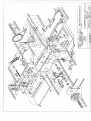
MECHANICA]- DRAWINGS AND PARTS LISTS
l5
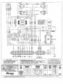
ELECTRICAL DIAGRAMS
19
\vARRANTY
20
DO NOT CONNECT TO ELECTRICAL
POWER DIJRING INSTAILATION
OR SERVICING OF OPERATOR
FOR ANY QIJESTIONS CONCERNING THE SAFETY OR
OPERATION OF T}IIS OPERATOR PLEASE CONTACT
MICANAN SYSTEMS AT
I
877-888-1116
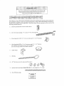
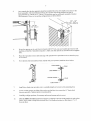
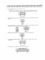
jackshaft door opemtor, please inspect the
Uootr deliverv of vour MICANAN SYSTEMS nedinn-du4'
ro
o,iit *r.fuf fy eo.aurDug.. Veriry ihat operator horsepower, vollage, phase and amperage conespond
the
have
received
available power supplv-and dooi applicition Check that along with vour operator vou
following standard hardware.
Ix
OPEN/CLOSE/STOP 3-bulton control stalion:
Ix
tt4l Drive chain package r 4' (1.2'r) c/w #41 connecting link
1x
Drive Sprooket4lBl2x 1"c/w2 sei sffews and %"x 1-U4"
ke)'rvav
;e
lp.\
,\g'.-'l
LrsA
Ix
Door Sprocket 41832 x l" c/w 2 set screws atrd %" x
No!e: Sprocket size and bore may vary according to
door size and bpe, shaft size and drum diameter
Ix
Chain keeper
Ix
Kryring
4
x
I
l/4" kq'way
3/8" boh hex nut, lock washer and flat washer
@@@%
1
x
pocket wbeel hand chain Modet PRO-LH) (2 x door height less
4'(1.2n))
@ffi@l@reffiaB,
Ix
Sei
ofwamins sigls
LI and PRO-LH medium duty jackshaft operaron are designed for conmercial high lift, vertical lift,
rcliing doors and rolling grilles provided that doors are ddven by a drive shaft with low duty cycles. Model
PRO-LH is ess€ntially the sane as nodel PRO-IJ vith the exc€ption that th€ PRO LH ope'ator
PRO
incorporates a chain hois. for manual operatio. ofthe doo'.
STANDARD OPER-ATOR WEIGHT: l5-5, ZBS
MOTOR:Int€mitte duty 1000 RPM motor witl high starting torque.
- Themally proiected by a built in themostat that cuts power io ihe motor and control circuit
when overheatjng.
- Horsepower: l/2HP
Voltage: 115V, 220V l-phase
REDUCTION: Prinary: (4L) V-belt and pulleys (1.5" to 7" dianeler)
Seco ary: #4I chain and sprockets
OUTPUT SHAFT SPEEDT 58 RPM
BRAKE : Solenoid actrated drun
aDd
brale shoe braking system to prevent
coasting and maintain door posjtion.
WIRING Tl?E (STANDARD): C-2 Widng consta pressure on
close, nomentary contact on open and
stop. Wircd to accept reversing edse,
cont ol, pholocelis, loops and OPEN/CLOSE devices.
'adio
NOTE: Ifnonentan contact on close (82) irtins L' d6ired: P.e-nstzll $e pprcle wne onro
terminal #5.
TRANSFORMER: 24VAC control cicuit, supplies power to drive cont'ol relays with l5VA power
available for extemal deYices.
LIMIT {)JUSTMENT:
4 micro svitches thal contol door tavel. These Limit swilches are acrivared by
tully adjustable screw t'"e
cams.
EMERGENCY DISCONNECT: Floor level cable discomect system with electrical cut out feanrre
alows pe$otr to manually operate tle door by hand (PRO
L,
or by chain hoist (PRO-LH)
h
case
of emergency.
CLUTCH: Adjustable ftctioD clutch to minimize damage to door operator, door or vehicles.
OP[RATOR DIMENSTONS:
t5 t/2'
BRACKET MOUNT
14 1/4'
a v16'
Do not allow childrer to play wilh door'
Before instalation, be sute that operator is suited for
Comect
a
!e
ofdoor
and applicalion
reveNing device to prevent entrapment if door is located near pedestrian iraffio
that
Place control alevice wiihin clear sight of the door but at a minimum dislance from lhe door so
lser
cainor reach movinJ: door panL wheo operaling
outdoor extemal devices should have securil)' feaiures to Fevent unauthorized operation ofthe door'
Never cross under
Pr€ss the
a
novins door
"OPEN' device or
use energency disconnect mechanism
if a person is trapped under ihe
Do not use discoDnect mechanism or rnanually operate door unless power
ha-q
been eleclricallv
Keep doors prope y naintained. Test door and seffice regularlv. Have a qualified service person make
rcpajf;s. Arl
u naintdi
ed doot systen cnuw cause
bjury ot death.
The owner or users musl understand the safery and operatiofl of door svstem lnsure that this
installation manual be located clos€ to the door svstem.
Note:
in stalled and
- Instaltation of operator must be done bv a qualified installer' Door must be Foperlv
prior
to
installation'
locks
wo*ing smoothly Remove all door
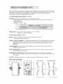
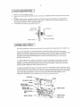
- Th€ PRO-LJ and PRO LH operalon have dual output shatu and mav be mounted on
left (standard) or right hand side of door. Ifbanding of operator must be rev€rsed,.loosen set
sc'e*s, remo"e arive sprocket and kelnvav and inslali onopposite side ofdrive shaft
LEFT HAND
SWITCHING IANDINO
RIGHT HAND
For the PRO-LH operator which incorporates a chain hoist mechanism the hedins of rhe
operator must be stated at time oforder. D€pending on instalation, if handing ol chain hoist is not
conect the hand chain mav hary in door opening. Ifthis is the case, swing chain offto the side and
hook it over the top of the doorjamb. Do noi attempt to reverse chain hoist on site
l
lnstall oontrol station away liom all moving door parts, within sight ofthe door and
5 ft
2
(1
.s
n) jlom the ground.
Install entrapment waming sigr next to control station.
6y
t-t""t
"rl
a
minimun of
1
:t.
below the drive shaft and as close to the
seneral rule, the door op€ra1or should be instalted
ddve shat and the door slaft
operator
the
door is possible. The ideal distance betwcen
.
mav
be waLl6ench momted or bracket
(38cm).
The
operator
afproximately lz" (30cm) to 15"
As
a
is
/shelf mounl;d. These two mounlins configurations are shoM below:
(io-38cm)
(30-38cn)
Mourt the operator to the wat1, hood or bench with 3/8"bolts, nuis and lvashers provided or wirh
lag bolts ani shiekls if installation requires it. Make sure that operator is secured but do not tighten
5.
Place door sprocket on door shaft and align with operator drive sprocket but do nol insert ke)'wav
lf
'7.
an optional chain spreader has been ordered
vith your operator. insiall as show. below:
Install drive chain oversprockels, cut to a suitable lengrh and oonnecl wilh connectins link
8.
Lower or raise operator 1() adjust cha;n tension so that there is no more than '1" chain slack
belween sprockels. Tighlen operator nounting bolts.
9.
Carefully re-alistr sprockets, ifnecessary and secure kelnvay and set screws-
t0
(For th€ PRO-LH nodel) Install hand chain by wnpping it through chain guard holes
js
wheel. Allow chain to hang down towards floor. Cut chain and connect so that chain
and pockei
2' to 3'
11.
12.
Run d rsconned chain
Install chain keeper to wallnear hand chain at appmximatelv-4 &omnoor'
ke}rnng lo end ol
Allacb
il
required
lrnk'
chain
rhrouch keyhole ofchan keeper and cul e{cess
ro wall
floor level disconnect lever was ordered in lieu of the chain keepet mounl
Allow
discnnnect
provided'
kevring
widr ;itable hardware. Attach both chai s together usjng
chain to be slishriv slaok when lever is in the up position
If
an
qtio'al
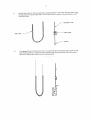
Adiuslmetri o f door tmvel is done bv noving the limit cans on the rhreaded shaft The position of
rhe a linir.$irches are laclory adjuned ed should nor be alrered Tlelimir'wirchesa'e
- "Open- limit switch: End of door travel in the tullv open positiotr
- "Ciosed" limit switch: End of door travel in the tullv closed position
feanrres
- "Advarccd open" limit switch: Us€d for opeD/close devices or rimer io close
reversing
from
prevent
reversing
device
- "Arlvancerl Ciosed" Limit switch: Used to
door when door is almost tullv closed'
To adilrst door tmvel:
l.
2.
Open cycle; Depress cam plate and spin "Open" limit cam awav &om "Open" limit switch to
increase door travel or spin "Open" linit cam towards the "Open" limit switch to decrease
door travel. After each adjustnent ensure that cam plate fullv engages h slots ofboth limit
Adiust "Open" limit cam so that door stops at the desired tullv open position
Close cycler Depress cam plare aid spin "Close" limit cam awav from "Close" limii switch to
increase door lravel or spitr "Close" limit cam towards the "Close" ljmit swilch to decrease
door travel. After each adjustment ensure lhat cam plate tuIv engages in slots ofboth limit
4.
Adjust "C1ose" limit cam so that door stops at the desied tully closed posilion
AI'VANCED OPEN IIMIT S1IVITCH
ADVANCED CIOSE LIMIT S1VITCH
CLOSE LIMIT SWTCH
t0
prior
Refer to electrical .liaglams inside conlrol box cover or al the end ofihis nanual
1()
conneciion
of
pox'er slpply or contrcl statioll.
TO REDUCI
THI RISK OF INJURY ORDEATH:
ALL ELECI RICAL CONNECTIONS SHOULD BE MADE BY A QUALIFI]]D SERVICE PFRSON
DO NOT ATTEM PT TO MAKE ELFCTRICAL CONNECTIONS TO OPERATOR UNI-ISS
POWI]R SUPPI-Y IIAS BEIN DISCONNECTED AT FUSE I]OX
OPI]RATORMUST BE CONNECTED IN ACCORDANCE TO LOCAL ELECTRICAL CODI']S
GROUNDED TO GREEN GROLIND I-UG LOCATED INSIDT']CONTROL BOX
^ND
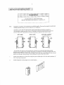
POWtrR WIRING: Use
1- 1i
8" (2.85 cn) dianeter holes for all power winng.
Cot]nect single phase power sxpply 120 VAC to lermnuls L (1jne) and N (neurral) on three pole
po$er .ennina' rrnt.
3
BUTTON CONTROL STATION
3-PHASE
@
a
CONTROL WIRING: Use 7/8" (2.22 cm) diameter holes for all control wiring
Note: Do not run conrrol rvires and powervires in srme conduit
- JnslallcoDtrol sLatio rvilhin clear sighl ofdoorbut away from all moving pans ol door or hard* arc.
tnstall Enlrapmeni warnins signnext to conxol station. Connect 3'button (opcn/close/stop) push bulton
smrion to teminals 2, 3,4 and 5. Refer to electrical diagran for corneclion oflwo 3-bulton slatioDs
NOTl,li Aiier electrical connecLions are.lade, nunually nore doorlo mid-position and, using the control
siaiion prcss the "Ope!" butlon tbr several seconds aDd lhenpress thc "Stop"button lfdoordjdnot
nove in corrcct direction vcrily wiring ofconlrol statioD
tl
1
.
R€verting Edgc devicc (nusl be normallv open contacl):
Note:
If
$e door is controlled bv anv device or wired in
such a manner thar lhe door is no!
@
3
2.
trxternal int€rlock: Remove jumper between terminals
1 and
2 and wire interlock between rhese two
@ @
2
1
3.
Railio control receiver: Wire standard radio receiver to separale radio stdp on side of control box or
6
I
4.
Single button
ope
closc device:
Wie
@
9
to leminals 7 and 8 on control teminal slrip
Loop det€ctors, photocells and other rev€rsing d€vices: Wire to tenninals
leminal strip.
@
6
@
4
a
6-
24
Volt pow€ri Wire to ieminals I
and 9 on control terminal slrip
CONTROL TERIIINAL STRIP
@ @
1
2
a
@ @ @
6
7
ao6
a
9
I
and 6 on control
12
1. Remove collelpin tapped to pulley
z. n"i"" a*"r' 'i,t **1iercloc-kwis; (loosen) until there is insufficienl tension to permit clutch to dr;ve
-:.
a.
-.uJ.ru
r, tigtt
trutuntil the tension on bclleville washers is sufficient to pem1il clutch to
allow clutch 10 slip if door is obstructed lt should be possible to stop
no\.ing door by hand ifcLutch is properlv adjustcd
I ocl clu.ch rur i.] pla. e o) n\rrmgcorLerpn
a.i'"
i"..
"n "tutch
U.r
rirood,ry
vill
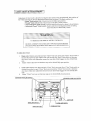
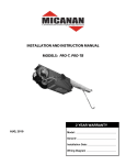
The brake adjustmenl is factory set and should onlvrcquire minor adjustment afterexlensive use
Verify brake adjustment by manually holditg in solenoid plunger. When brake is properlv
adjusied, tle brake shoe p;ds should make conplete conlact wiih brake drum with sufficient
bru
ke
spring tension lo stop and mainlain door when solenoid is de-energizcd Wlen solenoid is
energized, brake sbocs should release from drum with sufficient clearance to avoid conlact
between shoes and drum.
To adjust brake tension. tighten (to increase) or loosen (to decrease) nvlon lock nur on brake
spring boh. observe solenoid during electrical testing ofbrake Brake spring t€nsion musl b€
adjusied so thal solenoid should pull and release smoorhlv and q ietlv Too much or too litile
tension onbrake spring may cause solenoid to bum out
To adjust individual bmke shoes,loosennut on brake shoe adjustmentbolt and adjusiboh' When
properly adjusted, there shouldbe a smali clearancc beF{een adjustmentbolt and solenoidbrack€t
wh;n solenoid is de'enersized. When solenoid is energized, brakc shoes should move au'av from
drum wilh sufllicient clearance 10 avoid lriclion between brake shoe pad and drum Alier
adjustmcnts are nadc be sure to lightennuts on brake shoe adjustmenl bolls.
SOLENOID
SOLENOID LEVER
FRA}IE
BRAKE SHOE
ADJUSTHENT BOLTS
BRAKE SHOE
ADJUSTI,IENT NUT
BRAKE DRU},I
BRAKE SPRING
BOLT
BRAKE SPRING
BRAKE SHOE
BRAKE PAD
t3
with
The PRO-LJ and PRO-LH operators are equ;pped with an energencv disconnect device
feanre
This
inlerlocked power cul-out switch to manuallv operate door in case of energencvshould not be used to manuallv operate a maltuncrionine door'
-
TO REDUCE THE RISK OF INN-iRY OR DEATH:
DO NOT ATTEM?T TO USE EMERGENCY DISCONNECT
SYSTEM WHILE OPERATOR IS RUNNING'
POWER TO THE OPERATOR SHOTJLD BE TL'RNED OFF PRIOR
TO OPERATING DOOR MANUALLY.
t
. r
2.
3_
4.
operator is suppli€d with standard chain k€eper: Pu[ the discomect chain through the
ffoperator is supplied with optioml floor level discornect lever: Pull disconnect lever
domwards and lock jn place by bending lever around bracket lip
as shown.
For PRO-LI operators: Move door maDually. To r€hlm to electrical operation release
disconnect chain and allow to retum to original positionFor PRO-LH opemtols: Opetate door by pulling on hand chain To retum to elecrrical
operalion releas€ disconnect chain and allow to retum lo original posjtion Lock hard chain in
place (io Chain Keeper or Floor Level Disconnect) when not in use
14
nanual tuncrion olrbe doo' ever) 1 monrh\. Make \ure lbar door ruru cmoo rl) ll
door does nol manudll) open or cloqe lreely. ha\ e a qualified 'ewtce per'on make repairc Do
noi attempt to eleclrically operate a mattunctioning door'
tnsDecL
Everv 3 nonlhs:
1 Verify lhat door
area is kept clean. Remove any obstructions that would prevent proper
door operation.
2. Check for any excessive slack in chains lf ohain adjusbnent is required verifv and
adjust linit switches, if necessary.
3. Veri8, and adjusi clutch and brake (Do not lubricate).
4 Lubricare chdln', bearingc and limir 'bd[t'
5. VeriS, thai motor, soietroid and operator runs smoothlv and quiedv
Everv 6 months:
I
Veriry dghiness of all fasteners and set screws.
2. Veriry that operator is pmperly secured
3. Inspect manual disconnect
4. Veri& teision and condirion of V belt
Evefl
I
2 months:
a complete sewice check.
that insjde of contol box is clean and that grounding wires, ieminations and
power IermLnarion{ do nol sho$ \ignc olcono'i.n
3. Venfy dghiness of all teminal stnp srews and electrical connectjons.
4. Veriry power supply, voltage of inpnt teminals during op€ration
5. Veriry that cunent consumption ofoperator coresponds to nameplate information
I.
Perform
2.
Veify
o
F
U
z
Iz
&
EI
q{
F]
e'\,
Fi
fffirdm
>^ n ,)
I
o
z
z
A
E]
F
d
z
n
;
;
n
F.l
_2
[+
nc
s
z
,--6qf
:*F 14
,1
+-!xEr
==E
5 4t
,i
)
)
@
,@^
r+d^
A).6)
Y
rl
t6
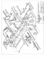
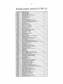
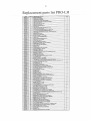
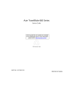
Replacement parts list PRO-LJ
]m-fN;
!!@!1
!!@gq
t4ss9!9!
:@120r'
lffi-
!Q9!99
ffi
@
o
u.l
It
o-
ah
^,1
F
z
Mmr
W
O
F.
z
z
O
t:
z i2
A
El
F
n
I
nI
o
;
l
U
;'l
fro
ti9
69
o2
;E{X q
!-:*E t
EEE
,ry
w%
/
:t
ET
w
.<
z
tI
l8
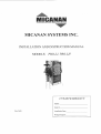
Replacement parts list PRO-LH
RNPHILUPSMACINESCREW632lNcn
qJsg@!
qq!99!
a9
t?34567
I
wmrno
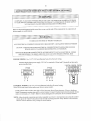
I,,ICANAII STRONGLY RECOTIMENDS THE
USE OF ENTRAPIIENT PFOTECTION
SYSTEMS IVNEN 82 (}IOMENTARY
COMTACT) WIRING ]S USED.
,A
CONIROL I9IRING OPTION ON CLOSE
THJS OPER TOR LEAVES THE FACTORY AITE A'C2'WRING - MEAN NG
THAT CONS-IANT PRESSURE IS REOUIRED TO CLOSE THE DOOR.
IF MOMENTARY OPERA'ION ON CLOSE ''82'WIRING .IS DESIRED, TI]EN
RE-INSTAIT THE FURPLE WRE ON TO TERMINAL iis.
/I\
A
Zl
IF STOP SUTTON NOT I]SED,
ADD.nffPER BEtuEEN 2 a J
13 aWG WIRE MUST
BE USED FOR FIELD CONNECTIONS,
NoTE: MlNl|lUn
=w_
MICANAN
rHE
llfoiMAroN coNr
|NED
HERiN B
PtuRElMY
ro
d0
S{ALL
Nor!!
3EPR0D6E0 ollllscLosED oR
0sE!l!4tr!!!Es!!!!3 !4!!
quRE
EXCEPT
*IEME3
and workmanship are free from defects for a peiod of
two years from ihe daie of invoice Malerials retumed ro Micanan deemed def€clive after examination
wil Le retumed ar rhe option of Micanz:r with repaired, new or re manufactured pans-
MICANAN SYSTEMS llananls that materjals
MICANAN SYSTEMS will noi be responsible fbr anv extra charges nlcurred in the process of reLuming
defeclive material. All retumed mateial must be received pre-paid or it 'till notbe accepted
This wananiy is limit€d, and in lieu of all other wananlv expressed or implied There is no expressed
liability due on the part ofthe seller.
MIGATIA]I
Commet.ial Door Opening Devices
MICANAN SYSTEMS INC.
HEAD OFFICE
PHOENIX
1380 St-Rcgis
1236 W. Southern Av€.
Dorval, Quebec
CanadA, HgP 2Ts
Suite 104
ATLANTA
2885 N. Bcrkeley Lak€ Rd.
Suite 7
Dul'rth, Gn
usA
85282
usA
30096
TEL: (514) 822-lll6
TEL: (180) 5s7-0070
'LEL: (678) 58.1-2543
1-877-888-1116
l-888-816-8584
FAx: (480) 5s7-8488
l-800,798-2543
FAX:
(51,1) 822-1118
FAx: (678) s84-2544
CIIICACO
706 Remington Rd.
Suite D
Schaumburg,
usA 60r73
Il
TtrL.: (847) 839-8303
FA*
l-800-6?0-8303
(847) 839-8308