1
Enfora Quad-Band SA-G+
AT Command Set
GSM1308AT001
Revision 1.00
10/29/08
AT Command Set Reference
Ver. 1.00
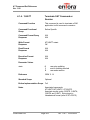
Document Title:
Enfora Quad-Band SA-G+
AT Command Set Reference
Version:
1.00
Date:
29 October 2008
Status:
Released
Document Control ID:
GSM1308AT001
General
All efforts have been made to ensure the accuracy of material provided in this
document at the time of release. However, the items described in this document are
subject to continuous development and improvement. All specifications are subject
to change without notice and do not represent a commitment on the part of Enfora,
Inc. Enfora, Inc. will not be responsible for any loss or damages incurred related to
the use of information contained in this document.
This product is not intended for use in life support appliances, devices or systems
where a malfunction of the product can reasonably be expected to result in personal
injury. Enfora, Inc. customers using, integrating, and/or selling this product for use in
such applications do so at their own risk and agree to fully indemnify Enfora, Inc. for
any damages resulting from illegal use or resale.
Copyright
Complying with all applicable copyright laws is the responsibility of the user. Without
limiting the rights under copyright, no part of this document may be reproduced,
stored in or introduced into a retrieval system, or transmitted in any form or by any
means (electronic, mechanical, photocopying, recording or otherwise), or for any
purpose, without the express written permission of Enfora, Inc.
Enfora may have patents, patent applications, trademarks, copyrights or other
intellectual property rights covering subject matter in this document. Except as
expressly provided in any written license agreement from Enfora, the furnishing of
this document does not give you any license to these patents, trademarks, copyrights
or other intellectual property.
©2002, 2003, 2004, 2005 Enfora, Inc. All rights reserved.
Enabler and Spider are either registered trademarks or trademarks of Enfora, Inc. in
the United States.
GSM1308AT001
ii
Ver. 1.00 – 10/29/2008
AT Command Set Reference
Ver. 1.00
Table of Contents
1.0
INTRODUCTION................................................................................................. 1
1.1.
1.2.
1.1.
1.2.
1.3.
2.
DOCUMENT SCOPE ............................................................................................... 1
PLATFORM REFERENCE AND USE ......................................................................... 1
COMMAND SYNTAX ............................................................................................. 1
REVISION HISTORY .............................................................................................. 3
REFERENCES ........................................................................................................ 4
STANDARD AT COMMANDS .............................................................................. 5
2.1.
COMMANDS SPECIFIED BY GSM REC. 07.07 ....................................................... 6
2.1.1.
General Commands .................................................................................... 6
2.1.1.1. AT+CGMI Request Manufacturer Identification ................................... 6
2.1.1.2. AT+CGMM Request Manufacturer Model Identification...................... 7
2.1.1.3. AT+CGMR Request Revision Identification.......................................... 8
2.1.1.4. AT+CGSN Request IMEI ....................................................................... 9
2.1.1.5. AT+CSCS Select TE Character Set ...................................................... 10
2.1.1.6. AT+CIMI Request IMSI ....................................................................... 11
2.1.1.7. AT+WS46 Select Wireless Network .................................................... 12
2.1.2.
Call Control Commands ........................................................................... 13
2.1.2.1. AT+CSTA Select Type of Address ...................................................... 13
2.1.2.2. ATD Dial command .............................................................................. 14
2.1.2.3. ATD> Originate Call Using Phonebook Memory ................................ 16
2.1.2.4. AT+CMOD Call mode ......................................................................... 18
2.1.2.5. AT+CHUP Hangup call ........................................................................ 19
2.1.2.6. AT+CBST Select Bearer service type .................................................. 20
2.1.2.7. AT+CRLP Radio link protocol parameters .......................................... 22
2.1.2.8. AT+CR Service Reporting Control ...................................................... 23
2.1.2.9. AT+CEER Extended Error Reporting .................................................. 25
2.1.2.10.
AT+CRC Cellular Result Codes ....................................................... 27
2.1.2.11.
AT+CSNS Single Numbering Scheme ............................................. 29
2.1.3.
Network Service Related Commands ........................................................ 31
2.1.3.1. AT+CNUM Subscriber Number ........................................................... 31
2.1.3.2. AT+CREG Network Registration Info ................................................. 32
2.1.3.3. AT+COPS Operator Selection .............................................................. 34
2.1.3.4. AT+CLCK Facility Lock ...................................................................... 38
2.1.3.5. AT+CPWD Change Password .............................................................. 41
2.1.3.6. AT+CLIP Calling Line Identification Presentation .............................. 44
2.1.3.7. AT+CLIR Calling Line Identification Restriction................................ 47
2.1.3.8. AT+COLP Connected Line Identification Presentation ....................... 49
2.1.3.9. AT+CCUG Closed User Group ............................................................ 51
2.1.3.10.
AT+CCFC Call Forwarding Number and Condition ....................... 53
2.1.3.11.
AT+CCWA Call Waiting ................................................................. 56
2.1.3.12.
AT+CHLD Call Hold and Multiparty ............................................. 58
GSM1308AT001
iii
Ver. 1.00 – 10/29/2008
AT Command Set Reference
Ver. 1.00
2.1.3.13.
AT+CUSD Unstructured Supplementary Service ........................... 60
2.1.3.14.
AT+CAOC Advice of Charge ......................................................... 62
2.1.3.15.
AT+CSSN Supplementary Service Notifications ............................ 63
2.1.3.16.
AT+CLCC List current calls............................................................ 67
2.1.3.17.
AT+CPOL Preferred Operator list ................................................... 70
2.1.3.18.
AT+COPN Read Operator Names ................................................... 72
2.1.4.
ME Control and Status Commands........................................................... 73
2.1.4.1. AT+CPAS Phone Activity Status ........................................................ 73
2.1.4.2. AT+CFUN Set Phone Functionality .................................................... 75
2.1.4.3. AT+CPIN Enter PIN ............................................................................ 76
2.1.4.4. AT+CSQ Signal Quality and Bit Error Rate ....................................... 80
2.1.4.5. AT+CPBS Select Phonebook Memory Storage .................................. 81
2.1.4.6. AT+CPBR Read Phonebook Entries ................................................... 84
2.1.4.7. AT+CPBF Find Phonebook Entries .................................................... 86
2.1.4.8. AT+CPBW Write Phonebook Entries ................................................. 88
2.1.4.9. AT+CMUT Mute Control .................................................................... 90
2.1.4.10.
AT+CACM Accumulated Call Meter.............................................. 91
2.1.4.11.
AT+CAMM Accumulated Call Meter Maximum ........................... 92
2.1.4.12.
AT+CPUC Price Per Unit and Currency Table ............................... 93
2.1.4.13.
AT+CCWE Call Meter Maximum Event ........................................ 94
2.1.4.14.
AT+CSVM Set Voicemail Number ................................................. 95
2.1.4.15.
AT+CLAE Set Language Event ...................................................... 97
2.1.4.16.
AT+CLAN Set Language ................................................................ 98
2.1.4.17.
AT+CMUX Set Multiplexing mode .............................................. 100
ME Errors ............................................................................................................... 103
2.1.4.18.
AT+CMEE Report Mobile Equipment Errors ............................... 103
2.1.5.
Commands from TIA IS-101 ................................................................... 105
2.1.5.1. AT+FCLASS GSM Class of Service................................................. 105
2.1.5.2. AT+VTS DTMF and Tone Generation ............................................. 106
2.1.5.3. AT+STTONE Start or Stop Generating a Tone................................. 108
2.2.
COMMANDS SPECIFIED BY GSM REC. 07.05 ................................................... 110
2.2.1.
General Configuration Commands ......................................................... 110
2.2.1.1. AT+CSMS Select Message Service .................................................. 110
2.2.1.2. AT+CPMS Preferred Message Storage ............................................. 111
2.2.1.3. AT+CMGF SMS Format ................................................................... 113
2.2.2.
Message Configuration Commands ........................................................ 114
2.2.2.1. AT+CSCA Service Center Address ................................................... 114
2.2.2.2. AT+CSMP Set Text Mode Parameters .............................................. 115
2.2.2.3. AT+CSDH Show Text Mode Parameters .......................................... 117
2.2.2.4. AT+CSCB Select Cell Broadcast Message Types ............................ 118
2.2.2.5. AT+CSAS Save Settings ................................................................... 120
2.2.2.6. AT+CRES Restore Settings ............................................................... 121
2.2.3.
Message Receiving and Reading Commands ......................................... 122
2.2.3.1. AT+CNMI New Message Indication to TE ....................................... 122
2.2.3.2. AT+CMGL List Messages................................................................. 125
GSM1308AT001
iv
Ver. 1.00 – 10/29/2008
AT Command Set Reference
Ver. 1.00
2.2.3.3. AT+CMGR Read Message ................................................................ 127
2.2.4.
Message Sending and Writing Commands ............................................. 129
2.2.4.1. AT+CMGS Send Message................................................................. 129
2.2.4.2. AT+CMSS Send Message from Storage ........................................... 130
2.2.4.3. AT+CMGW Write Message to Memory ........................................... 131
2.2.4.4. AT+CMGD Delete Message.............................................................. 132
2.2.4.5. AT+CMGC Send Command ............................................................. 133
2.3.
COMMANDS SPECIFIED BY ITU-T REC.V25TER AS REFERENCED BY GSM REC.
07.07 ......................................................................................................................... 134
2.3.1.
Generic TA Control Commands ............................................................. 134
2.3.1.1. ATZ Set All TA Parameters to Default Configuration ....................... 134
2.3.1.2. AT&F Set All TA Parameters to Factory Defined Configuration ...... 135
2.3.1.3. AT&V Display Current Profile ......................................................... 136
2.3.1.4. AT&W Save Current Settings .......................................................... 137
2.3.1.5. ATI Manufacturer Information About TA ........................................ 138
2.3.1.6. AT+GMI TA Manufacturer ID ......................................................... 139
2.3.1.7. AT+GMM TA Model ID .................................................................. 140
2.3.1.8. AT+GMR TA Revision Number ...................................................... 141
2.3.1.9. AT+GSN TA Serial Number ............................................................. 142
2.3.1.10.
AT+GCAP Request Overall Capabilities for TA .......................... 143
2.3.1.11.
ATS3 Command Line Termination Character ................................ 144
2.3.1.12.
ATS4 Response Formatting Character ......................................... 145
2.3.1.13.
ATS5 Editing Character................................................................ 146
2.3.1.14.
ATE Command Echo Mode.......................................................... 147
2.3.1.15.
ATQ Result Code Suppression ..................................................... 148
2.3.1.16.
ATV Response Format ................................................................. 149
2.3.1.17.
ATX CONNECT Result ............................................................... 150
2.3.1.18.
AT&C DCD Usage ....................................................................... 151
2.3.1.19.
AT&D DTR Usage ....................................................................... 152
2.3.1.20.
AT+IPR Fixed TE-TA Data Rate .................................................. 153
2.3.1.21.
AT+ICF TE-TA Character Framing .............................................. 155
2.3.1.22.
AT+IFC TE-TA Local Flow Control............................................. 156
2.3.1.23.
AT$IFC Default Value for AT+IFC ............................................. 157
2.3.1.24.
AT+ILRR TE-TA Local Rate Reporting ....................................... 158
2.3.2.
Call Control Commands ......................................................................... 159
2.3.2.1. T Tone Dialing ................................................................................. 159
2.3.2.2. P Pulse Dialing................................................................................. 160
2.3.2.3. A Answer a Call ................................................................................ 161
2.3.2.4. H Hook Control................................................................................. 162
2.3.2.5. O Return to Data State ...................................................................... 163
2.3.2.6. +++ Escape Sequence ....................................................................... 164
2.3.2.7. S0 Rings Before Automatic Answer ................................................. 165
2.3.2.8. S6 Pause Before Blind Dialing ......................................................... 166
2.3.2.9. S7 Wait for Completion .................................................................... 167
2.3.2.10.
S8 Dial Pause ................................................................................ 168
GSM1308AT001
v
Ver. 1.00 – 10/29/2008
AT Command Set Reference
Ver. 1.00
2.3.2.11.
3.
S10 Hang Up Delay ...................................................................... 169
STANDARDIZED GPRS AT COMMANDS ..................................................... 170
3.1
COMMANDS SPECIFIED BY GSM REC. 07.07 ................................................... 170
3.1.1 +CGDCONT Define PDP Context ............................................................ 170
3.1.2 +CGQREQ Quality of Service Profile (Requested) .................................. 172
3.1.3 +CGQMIN Quality of Service Profile (Minimum Acceptable) ................... 174
3.1.4 +CGATT GPRS Attach or Detach ............................................................ 176
3.1.5 +CGACT PDP Context Activate or Deactivate ........................................ 177
3.1.6 +CGDATA Enter Data State ..................................................................... 178
3.1.7 +CGPADDR Show PDP Address .............................................................. 179
3.1.8 +CGAUTO Automatic Response to a Network Request for PDP Context
Activation
................................................................................................. 180
3.1.9 +CGANS Manual Response to a Network Request for PDP Context
Activation
.................................................................................................... 182
3.1.10 +CGCLASS GPRS Mobile Station Class ................................................. 183
3.1.11 +CGEREP GPRS Event Reporting ......................................................... 184
3.1.12 +CGREG GPRS Network Registration Status ........................................ 186
3.1.13 +CGSMS Select Service for MO SMS Messages .................................... 188
3.1.14 D
Request GPRS Service ..................................................................... 189
3.1.15 S0 Automatic Response to a Network Request for PDP Context Activation .
............................................................................................................. 190
3.1.16 A
Manual Acceptance of a Network Request for PDP Context Activation ..
............................................................................................................. 191
3.1.17 H
Manual Rejection of a Network Request for PDP Context Activation 192
3.1.18 +CIND Indicator Control ......................................................................... 193
3.1.19 +CMER Mobile Termination Event Reporting ......................................... 195
4.
ENFORA SPECIFIC COMMANDS................................................................... 199
4.1.
SIM TOOLKIT COMMANDS .............................................................................. 199
4.1.1.
%SATC SET SIM Application Toolkit Configuration ............................. 199
4.1.2.
%SATE Send SAT Envelope Command ................................................ 201
4.1.3.
%SATR Send SAT Command Response ................................................ 202
4.1.4.
%SATT Terminate SAT Command or ................................................... 203
4.2.
BASIC AUDIO COMMANDS ............................................................................... 204
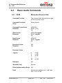
4.2.1.
$VGR Microphone Receiver Gain ........................................................ 204
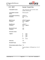
4.2.2.
$VGT Speaker Transmit Gain............................................................. 205
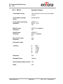
4.2.3.
$VLVL Speaker Volume ........................................................................ 206
4.2.4.
$VST Sidetone Volume ......................................................................... 207
4.3.
ADVANCED AUDIO COMMANDS....................................................................... 208
4.3.1.
$DFIR Configure Downlink FIR .......................................................... 208
4.3.2.
$UFIR Configure Uplink FIR Coefficients ........................................... 210
4.3.3.
$PREAMP Set Uplink Voice Parameters ............................................. 212
4.3.4.
$SPKCFG Set Downlink Voice Parameters ......................................... 214
4.3.5.
$VSELECT Voice Select ....................................................................... 217
4.3.6.
$MICANR Ambient Noise Reduction Control....................................... 219
GSM1308AT001
vi
Ver. 1.00 – 10/29/2008
AT Command Set Reference
Ver. 1.00
4.3.7.
$MICES Echo suppression Control ...................................................... 221
4.3.8.
$MICAEC Echo cancellation ................................................................ 223
4.4.
INPUT/OUTPUT COMMANDS ............................................................................. 225
4.4.1.
$IOCFG GPIO Configuration .............................................................. 225
4.4.2.
$IOBLKS GPIO Block Configuration ................................................... 227
4.4.3.
$IOGP(x) GPIO Bit Control ................................................................. 230
4.4.4.
$IOGPA GPIO Byte Control ................................................................ 232
4.4.5.
$IOPULEN GPIO Pullup Enable ......................................................... 234
4.4.6.
$IOPULUP GPIO Pullup Settings........................................................ 236
4.4.7.
$IOADC1 Read Analog to Digital Converter ......................................... 238
4.5.
UDP API COMMANDS ..................................................................................... 239
4.5.1.
$UDPAPI Modem API Address ............................................................ 239
4.5.2.
$APIPWD API Password ...................................................................... 240
4.5.3.
$APIOPT Enable API Optional Header Fields ................................... 241
4.6.
TCP API COMMANDS ...................................................................................... 244
4.6.1.
$TCPAPI TCP API Control .................................................................. 244
4.6.2.
$TCPSRC TCP API Source Ports ......................................................... 246
4.6.3.
$TCPRETRYTO TCP API Retry Timeout .............................................. 247
4.6.4.
$TCPIDLETO TCP API Idle Timeout ................................................... 248
4.6.5.
$TCPSTATS TCP API Statistics ............................................................ 249
4.6.6.
$TCPRESTRT TCP API Restart ............................................................ 251
4.7.
DYNAMIC IP/WAKEUP-KEEP ALIVE ................................................................ 252
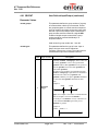
4.7.1.
$WAKEUP Modem to Server Wakeup/Keep........................................ 252
4.7.2.
$ACKTM Acknowledgment Message Period ........................................ 254
4.7.3.
$MDMID Modem ID............................................................................. 257
4.7.4.
$FRIEND Modem Friends .................................................................... 258
4.8.
PAD COMMANDS............................................................................................. 261
4.8.1.
$PADDST PAD Destination IP/Port .................................................... 261
4.8.2.
$PADSRC PAD Source Port ................................................................. 263
4.8.3.
$ACTIVE TCP PAD State ..................................................................... 264
4.8.4.
$PADBLK PAD Block Size ................................................................... 266
4.8.5.
$PADBS PAD Backspace Character .................................................... 267
4.8.6.
$PADFWD PAD Forward Character ................................................... 268
4.8.7.
$PADTO PAD Timeout Value .............................................................. 269
4.8.8.
$PADCMD PAD Command Features ................................................... 270
4.8.9.
$CONNTO TCP PAD Connection Timeout .......................................... 271
4.8.10. $IDLETO TCP PAD Idle Timeout ........................................................ 272
4.8.11. DP Dial Command for UDP PAD ....................................................... 273
4.8.12. DT Dial Command for TCP PAD ........................................................ 275
4.8.13. $PADDISC PAD disconnect method selection ..................................... 277
4.8.14. $PADESC PAD Escape Character ....................................................... 279
4.8.15. $PDPACT PDP Activate........................................................................ 280
4.8.16. $PDPDEACT PDP Deactivate .............................................................. 281
4.9.
EVENT PROCESSING COMMANDS ..................................................................... 282
4.9.1.
$EVENT User Defined Input/Output .................................................... 282
GSM1308AT001
vii
Ver. 1.00 – 10/29/2008
AT Command Set Reference
Ver. 1.00
4.9.2.
$EVTIM# User Defined Input Event Timers ......................................... 302
4.9.3.
$EVTEST Generate Test Input Event.................................................... 304
4.9.4.
$EVDEL Delete Event........................................................................... 305
4.9.5.
$EVDELA Delete Event ........................................................................ 306
4.9.6.
$STOATEV Store AT Command Events................................................. 307
4.9.7.
$ETSAV# Event Timer Save Configuration .......................................... 309
4.9.8.
$EVTOFF Event Engine Disable .......................................................... 311
4.10. REAL-TIME CLOCK COMMANDS ...................................................................... 312
4.10.1. $RTCALRM Real Time Clock Alarm ..................................................... 312
4.10.2. $RTCTIME Real Time Clock Time ....................................................... 315
4.10.3. $RTCWAKE Real Time Alarm Wake ..................................................... 318
4.10.4. $RTCCLRA Real Time Clock Clear Alarm............................................ 319
4.10.5. $RTCRSET RTC Report Reset State ...................................................... 320
4.11. NETWORK IDENTITY AND TIME ZONE COMMANDS .......................................... 322
4.11.1. AT$RTCUPD Update RTC with NITZ ................................................... 322
4.11.2. AT+CCLK Enable Setting and reading of RTC.................................... 324
4.11.3. AT+CTZR Generate URC with Time Zone ........................................... 325
4.11.4. AT+CTZU Enable saving of Time zone ................................................ 326
4.11.5. AT%CNIV Generate URC with network name ..................................... 327
4.11.6. AT%CTZV Generate URC with date and time ..................................... 328
4.12. IP ROUTER COMMANDS .................................................................................... 329
4.12.1. $HOSTIF Configure Host to Modem Interface .................................... 329
4.12.2. $CONN Initiate Network Connection ................................................... 331
4.12.3. $DISC Disconnect Network Connection............................................... 332
4.12.4. $LOCIP Display Local Modem to Host IP & ....................................... 333
4.12.5. $NETIP Display Network Assigned IP & ............................................. 334
4.13. NETWORK COMMANDS ...................................................................................... 335
4.13.1. $MSCLS Set GPRS Multislot Class ...................................................... 335
4.13.2. $CGEER Get PDP Context Activation Reject ...................................... 336
4.13.3. $LOCI Location Information ................................................................ 338
4.13.4. %BAND Frequency Band Information ................................................. 339
4.14. NETWORK MONITORING COMMANDS ................................................................. 341
4.14.1. $AREG Auto Registration ..................................................................... 341
4.14.2. $RESET Reset Modem .......................................................................... 343
4.14.3. $NETMON Monitor Network Availability ............................................. 344
4.15. FTP COMMANDS .............................................................................................. 347
4.15.1. $FTPCFG Configure FTP parameters ................................................. 347
4.15.2. $FTPOPEN Opens FTP Connection ...................................................... 350
4.15.3. $FTPDIR Directory Listing ................................................................... 352
4.15.4. $FTPGET Retrieve a Remote File ......................................................... 353
4.15.5. $FTPR Outputs block of file data onto .................................................. 355
4.15.6. $FTPCLOSE Closes the connection to FTP ........................................... 357
4.15.7. $FTPABORT Aborts current data operation with .................................. 358
4.15.8. $FTPCHDIR Change current working directory ................................... 359
4.16. MISCELLANEOUS COMMANDS ......................................................................... 360
GSM1308AT001
viii
Ver. 1.00 – 10/29/2008
AT Command Set Reference
Ver. 1.00
4.16.1.
4.16.2.
4.16.3.
4.16.4.
4.16.5.
4.16.6.
4.16.7.
4.16.8.
4.16.9.
4.16.10.
4.16.11.
4.16.12.
4.16.13.
4.16.14.
4.16.15.
4.16.17.
4.16.18.
4.16.19.
4.16.20.
4.16.21.
4.16.22.
4.16.23.
4.16.24.
4.16.25.
4.16.26.
4.16.27.
4.16.28.
4.16.29.
4.16.30.
4.16.31.
4.16.32.
4.16.33.
4.16.34.
4.16.35.
%NRG Network Registration and Service Selection .............................. 360
%CACM Query Accumulated Call Meter Using PUCT ........................ 363
%CAOC Query Current Call Meter Using ........................................... 364
%CPI Call Progress Information ......................................................... 365
%CTV Call Timer Value ....................................................................... 368
%SNCNT Query (or Reset) the Byte ..................................................... 369
%CGAATT Automatic Attach and Detach ............................................. 370
%CGPPP PPP Negotiation Selection .................................................. 371
%CGPCO Set Type of Authentication, ................................................. 372
%ALS Alternating Line Service ......................................................... 375
%CGREG GPRS Extended Registration State .................................. 376
%CSTAT Unsolicited SIM status ....................................................... 378
%SLEEP Select level of sleep mode................................................... 379
%EM Engineering Mode................................................................... 381
$PKG Request Firmware Package .................................................... 382
$SNDMSG Send Test message ........................................................... 383
$SMSDA Destination Address for SMS ............................................. 384
$SMSDAEN Enable/Disable AT ......................................................... 387
$UDPMSG Send and Receive UDP Messages .................................. 390
$LUPREJ Get LUP Reject Cause ...................................................... 393
$SRN Module Serial Number ............................................................. 395
$MSGSND Message Send .................................................................. 396
$OFF Power off command................................................................ 398
$OFFDLY Power off delay ................................................................ 399
$PWRMSG Power On Message .......................................................... 401
$SIMDTC SIM Detection Enable / Disable ....................................... 403
$BBCHG Recharge Backup Battery .................................................. 404
%MEPD MEPD Configuration Data ................................................ 406
$ICCID Integrated Circuit Card ID .................................................. 409
$RICSD CSD Ring Indicate ............................................................... 410
$USRVAL User Value ........................................................................ 411
$SPN Software Part Number ............................................................. 413
$PASSWD Set authorization for AT................................................... 414
$DEVTYP Query the device type ...................................................... 416
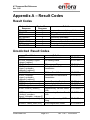
APPENDIX A – RESULT CODES ............................................................................. 417
RESULT CODES ............................................................................................................ 417
UNSOLICITED RESULT CODES ..................................................................................... 417
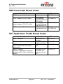
SMS UNSOLICITED RESULT CODES ............................................................................. 418
SAT APPLICATION TOOLKIT RESULT CODES ............................................................... 418
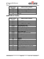
APPENDIX B – ERROR CODES ............................................................................... 419
GENERAL ERROR CODES.............................................................................................. 419
GPRS ERROR CODES ................................................................................................... 420
SMS ERROR CODES ..................................................................................................... 421
RELEASE CAUSES FOR EXTENDED ERROR REPORTING (+CEER) ................................ 423
GSM1308AT001
ix
Ver. 1.00 – 10/29/2008
AT Command Set Reference
Ver. 1.00
APPENDIX C – DEFAULT AT VALUES ................................................................. 425
GSM1308AT001
x
Ver. 1.00 – 10/29/2008
AT Command Set Reference
Ver. 1.00
1.0
Introduction
1.1.
Document Scope
The following documentation pertains to the AT Command Set to be used in
conjunction with the Enfora GSM/GPRS OEM module, the Enabler IIIG.
1.2.
Platform Reference and Use
The Enabler IIIG will be referred to using various terms, to include: MS (Mobile
Station), TA (Terminal Adapter), DCE (Data Communication Equipment), or ME
(Mobile Equipment).
The Enabler IIIG can be controlled via the use of a DTE (Data Terminal
Equipment) platform by issuing the AT commands via a serial interface.
1.1.
Command Syntax
The attention or “AT” prefix is required prior to entering any command. All
commands require a carriage return or <CR> following the entry of the
desired command. All command responses are encapsulated by a
carriage return and line feed or <CR><LF>. The ASCII display of these
characters is suppressed with only the modem response being presented.
AT message concatenation can be done using the ; <semicolon> between
commands.
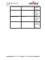
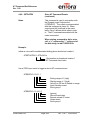
The following examples demonstrate the potential usage of AT commands
presented:
Type
Command Format Query
Example
AT+GXXX=?
Command Read
AT+GXXX?
GSM1308AT001
Page 1
Description
When
entered will
return the
command
format and
value
ranges.
When
entered will
return the
current value
Ver. 1.00 – 10/29/2008
AT Command Set Reference
Ver. 1.00
assigned to
the
command.
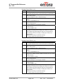
Command Write
AT+GXXX=<value>,<value>,… When
entered will
set the
command to
specified
value(s).
Command Execution
AT+GXXX
When
entered will
execute the
specified
command.
Command Concatenation AT+CRC=1;S0=1
When
entered it will
execute both
the CRC and
S0
command.
GSM1308AT001
Page 2
Ver. 1.00 – 10/29/2008
AT Command Set Reference
Ver. 1.00
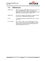
1.2.
Revision History
Date
10/29/08
GSM1308AT001
Rev.
1.00
Author
Diane Oneil
Page 3
Description
Initial Release
Ver. 1.00 – 10/29/2008
AT Command Set Reference
Ver. 1.00
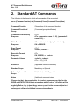
1.3.
References
[GSM 07.05]
GTS 07.05: January 1998 (GSM 07.05 version 5.5.0) Use of
Data Terminal Equipment - Data Circuit terminating
Equipment (DTE - DCE) interface for Short Message Service
(SMS) and Cell Broadcast Service (CBS), ETSI
[GSM 07.07]
ETS 300 916: February 1998 (GSM 07.07 version 5.5.0) AT
command set for GSM Mobile Equipment (ME)
[T.32]
T.32 (08/95) Asynchronous facsimile DCE control - service
class 2, ITU
[T V.25_TER]
(ITU-T V.25 ter, 1997) ITU-T Recommendation V.25 ter;
Series V: data communication over the telephone network;
Interfaces and voiceband modems; Serial asynchronous
automatic dialing and control, ITU
GSM1308AT001
Page 4
Ver. 1.00 – 10/29/2008
AT Command Set Reference
Ver. 1.00
2. Standard AT Commands
The following is the format in which all commands will be presented.
xx.xx (Command Number) Atx(Command) Xxxxx(Command Description)
Command Function
(Description of the command function)
Command Functional
Group
(Functional group identification)
Command Format Query
Response
ATx=?
ATx: (parameter1 name 1 – 15), (parameter2
name 1-10),…
Write Format
Response
ATx=<value>,<value>[,<optional value>],…
OK or ERROR
Read Format
Response
ATx?
<value>,<value>,…
Execution Format
Response
ATx
OK, ERROR, or <value>
Parameter Values
<value1>,<value2>
ATx: (1-15),(1-10)
Reference
(Applicable standard reference)
Standard Scope
Mandatory or Optional
Enfora Implementation
Scope
Full, Partial, or Not Supported
Notes
(Additional command notes)
Please note that, where applicable, the <value> responses provided for the
READ and EXECUTION formats are modem default values. All efforts will be
made by Enfora, Inc. to keep these values current in the documentation but
will not be responsible for any differences that may occur as a result
subsequent software builds and version enhancements.
GSM1308AT001
Page 5
Ver. 1.00 – 10/29/2008
AT Command Set Reference
Ver. 1.00
2.1. Commands Specified by GSM Rec. 07.07
2.1.1. General Commands
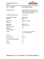
2.1.1.1.
AT+CGMI
Request Manufacturer Identification
Command Function
This command is used to obtain the
manufacturer identification information.
Command Functional
Group
Equipment Information
Command Format Query
Response
AT+CGMI=?
OK
Write Format
Response
N/A
N/A
Read Format
Response
N/A
N/A
Execution Format
Response
AT+CGMI
Enfora, Inc.
OK
Parameter Values
N/A
Reference
GSM Ref. 07.07 Chapter 5.1
Standard Scope
Optional
Enfora Implementation Scope Full
Notes
GSM1308AT001
Return value is manufacturer specific.
Page 6
Ver. 1.00 – 10/29/2008
AT Command Set Reference
Ver. 1.00
2.1.1.2.
AT+CGMM
Request Manufacturer Model
Identification
Command Function
This command is used to obtain the
manufacturer model identification
information.
Command Functional
Group
Equipment Information
Command Format Query
Response
AT+CGMM=?
OK
Write Format
Response
N/A
N/A
Read Format
Response
N/A
N/A
Execution Format
Response
AT+CGMM
Enabler IIIG Modem
OK
Parameter Values
N/A
Reference
GSM Ref. 07.07 Chapter 5.2
Standard Scope
Optional
Enfora Implementation Scope Full
Notes
GSM1308AT001
Return value is manufacturer specific.
Page 7
Ver. 1.00 – 10/29/2008
AT Command Set Reference
Ver. 1.00
2.1.1.3.
AT+CGMR
Request Revision Identification
Command Function
This command is used to obtain the
manufacturer embedded firmware revision
information.
Command Functional
Group
Equipment Information
Command Format Query
Response
AT+CGMR=?
OK
Write Format
Response
N/A
N/A
Read Format
Response
N/A
N/A
Execution Format
Response
AT+CGMR
<revision>
OK
Parameter Values
N/A
Reference
GSM Ref. 07.07 Chapter 5.3
Standard Scope
Optional
Enfora Implementation Scope Full
Notes
GSM1308AT001
Return value is manufacturer specific.
Page 8
Ver. 1.00 – 10/29/2008
AT Command Set Reference
Ver. 1.00
2.1.1.4.
AT+CGSN
Request IMEI
Command Function
This command is used to obtain the
manufacturer International Mobile
Equipment Identity (IMEI).
Command Functional
Group
Equipment Information
Command Format Query
Response
AT+CGSN=?
OK
Write Format
Response
N/A
N/A
Read Format
Response
N/A
N/A
Execution Format
Response
AT+CGSN
0044008824900101
OK
Parameter Values
N/A
Reference
GSM Ref. 07.07 Chapter 5.4
Standard Scope
Optional
Enfora Implementation Scope Full
Notes
Return value is manufacturer specific.
The TA returns the International Mobile
station Equipment Identifier (IMEI).
GSM1308AT001
Page 9
Ver. 1.00 – 10/29/2008
AT Command Set Reference
Ver. 1.00
2.1.1.5.
AT+CSCS
Select TE Character Set
Command Function
This command is used to select the
terminal equipment character set.
Command Functional
Group
State Control
Command Format Query
Response
AT+CSCS=?
+CSCS: <"GSM", "IRA" , "PCCP437" ,
"PCDN" , "8859-1" , "HEX" , “UCS2”>
OK
Write Format
Response
AT+CSCS=<chset>
OK
Read Format
Response
AT+CSCS?
+CSCS: “PCCP437”
OK
Execution Format
Response
N/A
N/A
Parameter Values
<chset>
"GSM"
"IRA"
"PCCP437"
"PCDN"
"8859-1"
"HEX"
"UCS2"
Reference
GSM Ref. 07.07 Chapter 5.5
Standard Scope
Mandatory
Enfora Implementation Scope Partial
Notes
GSM1308AT001
Values are based on character set support.
Page 10
Ver. 1.00 – 10/29/2008
AT Command Set Reference
Ver. 1.00
2.1.1.6.
AT+CIMI
Request IMSI
Command Function
This command is used to obtain the
International Mobile Subscriber Identity
(IMSI) value assigned to the SIM.
Command Functional
Group
Equipment Information
Command Format Query
Response
AT+CIMI=?
OK
Write Format
Response
N/A
N/A
Read Format
Response
N/A
N/A
Execution Format
Response
AT+CIMI
310260101xxxxx
OK
Parameter Values
N/A
Reference
GSM Ref. 07.07 Chapter 5.6
Standard Scope
Optional
Enfora Implementation Scope Full
Notes
Return value is manufacturer specific.
The TA returns the International Mobile
Subscriber Identity (IMSI).
GSM1308AT001
Page 11
Ver. 1.00 – 10/29/2008
AT Command Set Reference
Ver. 1.00
2.1.1.7.
AT+WS46
Select Wireless Network
Command Function
This command is used to select the
wireless network to operate with the TA.
Command Functional
Group
Network
Command Format Query
Response
AT+WS46=?
+WS46: <12>
OK
Write Format
Response
AT+WS46=<n>
OK
Read Format
Response
AT+WS46?
+WS46: 12
OK
Execution Format
Response
N/A
N/A
Parameter Values
<n>
12
(GSM Digital Cellular)
Reference
GSM Ref. 07.07 Chapter 5.9
Standard Scope
Optional
Enfora Implementation Scope Partial
Notes
GSM1308AT001
Will provide available network interface
support selection.
Page 12
Ver. 1.00 – 10/29/2008
AT Command Set Reference
Ver. 1.00
2.1.2. Call Control Commands
2.1.2.1.
AT+CSTA
Select Type of Address
Command Function
This command is used to select the type of
number to be used for further dialing
commands.
Command Functional
Group
Call Control
Command Format Query
Response
AT+CSTA=?
+CSTA: <129 or 145>
OK
Write Format
Response
AT+CSTA=<n>
OK
Read Format
Response
AT+CSTA?
+CSTA: 129
OK
Execution Format
Response
N/A
N/A
Parameter Values
<n>
129
(Dialing string without
International Access Code
character “+”)
145
(Dialing string with International
Access Code character “+”)
Reference
GSM Ref. 07.07 Chapter 6.1
Standard Scope
Mandatory
Enfora Implementation Scope Full
Notes
GSM1308AT001
N/A
Page 13
Ver. 1.00 – 10/29/2008
AT Command Set Reference
Ver. 1.00
2.1.2.2.
ATD
Dial command
Command Function
This command is used to setup an
outbound voice or data call.
Command Functional
Group
Call Control
Command Format Query
Response
N/A
N/A
Write Format
Response
N/A
N/A
Read Format
Response
N/A
N/A
Execution Format
Response
ATD1234567I;
NO DIALTONE or
NO CARRIER or
CONNECT <value> or
BUSY or
OK
Parameter Values
<n>
V.25ter Dialing Digits = 0 – 9, *, #, +, A, B,
C
V.25ter Dialing Modifiers = , (comma), T, P,
!, @, W
<cmod>
GSM Modifier Characters
I = Restrict CLI, i = Allow CLI
<;>
Semicolon after dialing string or modifier
indicates voice call and forces TA into
command mode after successful
completion.
GSM1308AT001
Page 14
Ver. 1.00 – 10/29/2008
AT Command Set Reference
Ver. 1.00
2.1.2.2.
ATD
Dial command
(continued)
Reference
GSM Ref. 07.07 Chapter 6.2
Standard Scope
Mandatory
Enfora Implementation Scope Full
Notes
Modem Responses
NO DIALTONE
if no dial tone is detected
NO CARRIER
if call cannot be set up
CONNECT <value>
when connected in a non-voice call (data
mode) <value> dependent on ATX setting
BUSY
if dialed number is busy
OK
when successful voice call or TA ends
current call and returns to command mode
Example:
ATD5551212I
The TA will dial the number 5551212 and will block the CLI when made.
GSM1308AT001
Page 15
Ver. 1.00 – 10/29/2008
AT Command Set Reference
Ver. 1.00
2.1.2.3.
ATD>
Originate Call Using Phonebook Memory
Command Function
This command is used to setup an
outbound voice or data call from a specific
phonebook location.
Command Functional
Group
Call Control
Command Format Query
Response
ATD?
ATD<storage><n><cmod><;>
Write Format
Response
N/A
N/A
Read Format
Response
N/A
N/A
Execution Format
Response
ATD>SD12I;
NO DIALTONE or
NO CARRIER or
CONNECT <value> or
BUSY or
OK
Parameter Values
<storage>
Phonebook Location
<n>
Storage location number in selected
phonebook
<cmod>
GSM Modifier Characters
I = Restrict CLI, i = Allow CLI
<;>
Semicolon after dialing string or modifier
forces TA into command mode after
successful completion.
Reference
GSM Ref. 07.07 Chapter 6.3
Standard Scope
Mandatory
Enfora Implementation Scope Full
GSM1308AT001
Page 16
Ver. 1.00 – 10/29/2008
AT Command Set Reference
Ver. 1.00
2.1.2.3.
ATD>
Originate Call Using Phonebook
Memory (continued)
Notes
Phonebook Location Values
"EN"
"FD"
"LD"
"BD"
"SD"
"LR"
"AD"
"LM"
"AF"
"SM"
“UD”
SIM (or ME) emergency number
SIM fixed-dialing-phonebook
SIM last-dialing-phonebook
SIM barred-dialing phonebook
SIM service numbers
Last received numbers (nonstandard)
Abbreviated dialing numbers (nonstandard)
Last missed numbers (nonstandard)
comb. of fixed and abbrev. dialing
phonebook (nonstandard)
comb. of fixed and abbrev. dialing
phonebook (nonstandard)
User defined
Modem Responses
NO DIALTONE
if no dial tone is detected
NO CARRIER
if call cannot be set up
CONNECT <value>
when connected in a non-voice call (data
mode) <value> dependent on ATX setting
BUSY
if dialed number is busy
OK
when successful voice call or TA ends
current call and returns to command mode
Example:
ATD>FD2I
The TA will dial the number stored in memory location 2 the fixed-dialing
phonebook. The call will block the CLI when made.
GSM1308AT001
Page 17
Ver. 1.00 – 10/29/2008
AT Command Set Reference
Ver. 1.00
2.1.2.4.
AT+CMOD
Call mode
Command Function
This command is used to select the type of
call mode desired for following dial (D)
and/or answer (A) commands.
Command Functional
Group
Call Control
Command Format Query
Response
AT+CMOD=?
+CMOD: (0-3)
OK
Write Format
Response
AT+CMOD=<mode>
OK
Read Format
Response
AT+CMOD?
+CMOD: 0
OK
Execution Format
Response
N/A
N/A
Parameter Values
<mode>
0
Single service
1
Alternating voice/fax (teleservice
61)
2
Alternating voice/data
(bearer service 61)
3
Voice followed by data
(bearer service 81)
Reference
GSM Ref. 07.07 Chapter 6.4
Standard Scope
Mandatory
Enfora Implementation Scope Full
Notes
GSM1308AT001
Default value will be 0. AT&F, restore
factory defaults will reset this value to 0.
Page 18
Ver. 1.00 – 10/29/2008
AT Command Set Reference
Ver. 1.00
2.1.2.5.
AT+CHUP
Hangup call
Command Function
This command is used to end all active
calls.
Command Functional
Group
Call Control
Command Format Query
Response
AT+CHUP=?
OK
Write Format
Response
N/A
N/A
Read Format
Response
N/A
N/A
Execution Format
Response
AT+CHUP
OK
Parameter Values
N/A
Reference
GSM Ref. 07.07 Chapter 6.5
Standard Scope
Mandatory
Enfora Implementation Scope Full
Notes
GSM1308AT001
Default value will be 0. AT&F, restore
factory defaults will reset this value to 0.
Page 19
Ver. 1.00 – 10/29/2008
AT Command Set Reference
Ver. 1.00
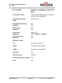
2.1.2.6.
AT+CBST
Select Bearer service type
Command Function
This command is used to select the bearer
service with data rate and the connection
element to be used when data calls are
originated.
Command Functional
Group
Call Control
Command Format Query
Response
AT+CBST=?
+CBST: (0-7, 12, 14, 65, 66, 68, 70, 71,75),
(0-1), (0-3)
Write Format
Response
AT+CBST=<baud rate>,<name>,<ce>
OK/ERROR
Read Format
Response
AT+CBST?
+CBST: 7,0,1
Execution Format
Response
N/A
N/A
Parameter Values
<baud rate>
0
1
2
3
4
5
6
7
12
14
65
GSM1308AT001
Page 20
autobauding (automatic selection of
the speed; this setting is possible in
case of 3.1 kHz modem and nontransparent service)
300 bps (V.21)
1200 bps (V.22)
1200/75 bps (V.23)
2400 bps (V.22bis)
2400 bps (V.26ter)
4800 bps (V.32)
9600 bps (V.32)
9600 bps (V.34)
14400 bps (V.32)
300 bps (V.110)
Ver. 1.00 – 10/29/2008
AT Command Set Reference
Ver. 1.00
2.1.2.6.
AT+CBST
Select Bearer service type
(continued)
66
68
70
71
75
<name>
0
1
1200 bps (V.110)
2400 bps (V.110 or X.31 flag
stuffing)
4800 bps (V.110 or X.31 flag
stuffing)
9600 bps (V.110 or X.31 flag
stuffing)
14400 bps (V.110 or X.31 flag
stuffing)
data circuit asynchronous (UDI or
3.1 kHz modem)
data circuit synchronous (UDI or 3.1
kHZ modem)
<ce>
0
1
2
3
transparent
non-transparent
both, transparent preferred
both, non-transparent preferred
Reference
GSM Ref. 07.07 Chapter 6.7
Standard Scope
Mandatory
Enfora Implementation Scope Partial
Notes
N/A
Example:
AT+CBST=7,0,1
Non-transparent
No name
9600 bps (V.32)
GSM1308AT001
Page 21
Ver. 1.00 – 10/29/2008
AT Command Set Reference
Ver. 1.00
2.1.2.7.
AT+CRLP
Radio link protocol parameters
Command Function
This command is used to select the radio
link protocol parameters.
Command Functional
Group
Call Control
Command Format Query
Response
AT+CRLP=?
+CRLP: (0-61), (0-61), (39-255), (1-255)
OK
Write Format
Response
AT+CRLP=<iws>,<mws>,<T1>,<N2>
OK/ERROR
Read Format
Response
AT+CRLP?
+CRLP: 61, 61, 48, 6
OK
Execution Format
Response
N/A
N/A
Parameter Values
<iws>
IWF to MS window size
values = 0 to 61 (61 recommended)
<mws>
MS to IWF window size
values = 0 to 61 (61 recommended)
<T1>
Acknowledgement timer
values = halfrate >380ms
(480 recommended)
fullrate >600ms
(780 recommended)
`
<N2>
Retransmission attempts
values = >0 (6 recommended)
Reference
GSM Ref. 07.07 Chapter 6.8
Standard Scope
Mandatory
Enfora Implementation Scope Partial
Notes
GSM1308AT001
N/A
Page 22
Ver. 1.00 – 10/29/2008
AT Command Set Reference
Ver. 1.00
2.1.2.8.
AT+CR
Service Reporting Control
Command Function
This command is used to control the display
of intermediate result code (+CR <serv>)
status.
Command Functional
Group
Response Control
Command Format Query
Response
AT+CR=?
+CR: (0,1)
OK
Write Format
Response
AT+CR=<mode>
OK
Read Format
Response
AT+CR?
+CR: 0
OK
Execution Format
Response
N/A
N/A
Parameter Values
<mode>
0
1
disable
enable
<serv>
ASYNC
asynchronous transparent
SYNC
synchronous transparent
REL ASYNC asynchronous nontransparent
REL SYNC synchronous nontransparent
Reference
GSM Ref. 07.07 Chapter 6.9
Standard Scope
Mandatory
Enfora Implementation Scope Full
GSM1308AT001
Page 23
Ver. 1.00 – 10/29/2008
AT Command Set Reference
Ver. 1.00
2.1.2.8.
Notes
GSM1308AT001
AT+CR
Service Reporting Control
(continued)
If enabled, the intermediate result code is
transmitted at the point during connect
negotiation at which the TA has determined
which speed and quality of service will be
used, before any error control or data
compression reports are transmitted, and
before any final result code (e.g.
CONNECT) is transmitted.
Page 24
Ver. 1.00 – 10/29/2008
AT Command Set Reference
Ver. 1.00
2.1.2.9.
AT+CEER
Extended Error Reporting
Command Function
This command is used to control the display
of extended result codes for last
unsuccessful call setup, in-call modification,
last call release, last short message, or last
GPRS session.
Command Functional
Group
Call Control
Command Format Query
Response
AT+CEER=?
OK
Write Format
Response
N/A
N/A
Read Format
Response
N/A
N/A
Execution Format
Response
AT+CEER
+CEER: < DEFBY >, <ORIGSIDE>,
<ORIGIN_ENTITY>, <VALUE>[,ERROR
DESCRIPTION]
OK
Parameter Values
<DEFBY> (defined by)
0 - Standard
1 - Enfora
<ORIGSIDE> (originating side)
0 - Network
1 - MS
<ORIGIN_ENTITY>:
0 - SIM
1 - ACI
2 - RLP
3 - RR
4 - MM
5 - CC
6 - SS
GSM1308AT001
Page 25
Ver. 1.00 – 10/29/2008
AT Command Set Reference
Ver. 1.00
2.1.2.9.
AT+CEER
Extended Error Reporting
(continued)
7 - SMSCP
8 - SMSRP
9 - SMSTP
10 - GMM
11 - SM
12 - FAD
13 - T30
14 - GRR
15 - PPP
16 - LLC
17 - SNDCP
18 - PKTIO
19 - PSI
<VALUE>
See AT+CEER Table in Appendix B
<ERROR DESCRIPTION>
Optional extended error description
Reference
GSM Ref. 07.07 Chapter 6.10, Enfora
Specific responses
Standard Scope
Optional
Enfora Implementation Scope Full
Notes
GSM1308AT001
N/A
Page 26
Ver. 1.00 – 10/29/2008
AT Command Set Reference
Ver. 1.00
2.1.2.10.
AT+CRC
Cellular Result Codes
Command Function
This command is used to control the display
of extended incoming call information.
Command Functional
Group
Response Control
Command Format Query
Response
AT+CRC=?
+CRC: (0,1)
OK
Write Format
Response
AT+CRC=<mode>
OK
Read Format
Response
AT+CRC?
+CRC: 0
OK
Execution Format
Response
N/A
N/A
GSM1308AT001
Page 27
Ver. 1.00 – 10/29/2008
AT Command Set Reference
Ver. 1.00
2.1.2.10.
AT+CRC
Cellular Result Codes
(continued)
Parameter Values
<mode>
0
1
disable
enable
<type>
ASYNC
asynchronous transparent
SYNC
synchronous transparent
REL ASYNC asynchronous nontransparent
REL SYNC synchronous non-transparent
FAX
facsimile (TS 62)
VOICE
normal voice (TS 11)
VOICE/ XXX voice followed by data (BS
81) ( XXX is ASYNC, SYNC,
REL ASYNC or REL SYNC)
ALT VOICE/ XXX alternating voice/data,
voice first (BS 61)
ALT XXX/VOICE alternating voice/data,
data first (BS 61)
ALT VOICE/FAX alternating voice/fax,
voice first (TS 61)
ALT FAX/VOICE alternating voice/fax,
fax first (TS 61)
Reference
GSM Ref. 07.07 Chapter 6.11
Standard Scope
Mandatory
Enfora Implementation Scope Full
Notes
GSM1308AT001
When enabled, an incoming call is indicated
to the TE with unsolicited result code
+CRING: <type> instead of the normal
RING.
Page 28
Ver. 1.00 – 10/29/2008
AT Command Set Reference
Ver. 1.00
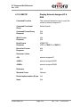
2.1.2.11.
AT+CSNS
Single Numbering Scheme
Command Function
This command selects the bearer or
teleservice to be used when mobile
terminated single numbering scheme call is
established. Parameter values set with
+CBST command shall be used when
<mode> equals to a data service. If
+CBST parameter is set to a value that is
not applicable to single numbering calls,
ME/TA shall map the value to the closest
valid one. E.g. if user has set <speed>=71,
<name>=0 and <ce>=1 (non-transparent
asynchronous 9600 bps V.110 ISDN
connection) for mobile originated calls,
ME/TA shall map the values into nontransparent asynchronous 9600 bps V.32
modem connection when single numbering
scheme call is answered.
Command Functional
Group
Call Control
Command Format Query
Response
AT+CSNS=?
+CSNS: (0-7)
OK
Write Format
Response
AT+CSNS = <mode>
OK
Read Format
Response
AT+CSNS?
+CSNS: 0
OK
Execution Format
Response
N/A
N/A
GSM1308AT001
Page 29
Ver. 1.00 – 10/29/2008
AT Command Set Reference
Ver. 1.00
2.1.2.11.
AT+CSNS
Single Numbering Scheme
(continued)
Parameter Values
<mode>
0
1
2
3
4
5
6
7
voice
alternating voice/fax, voice first
(TS 61)
fax (TS 62)
alternating voice/data, voice first (BS
61)
data
alternating voice/fax, fax first
(TS 61)
alternating voice/data, data first
(BS 61)
voice followed by data (BS 81)
Reference
GSM Ref. 07.07 Chapter 6.17
Standard Scope
Optional
Enfora Implementation Scope Full
Notes
GSM1308AT001
Fax not supported
Page 30
Ver. 1.00 – 10/29/2008
AT Command Set Reference
Ver. 1.00
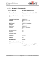
2.1.3. Network Service Related Commands
2.1.3.1.
AT+CNUM
Subscriber Number
Command Function
This command is used to obtain the
MSISDNs related to the subscriber.
Command Functional
Group
Network Information
Command Format Query
Response
AT+CNUM=?
OK
Write Format
Response
N/A
N/A
Read Format
Response
N/A
N/A
Execution Format
Response
AT+CNUM
+CNUM: “Line1”, “1 719 xxx xxxx”, 145 OK
Parameter Values
N/A
Reference
GSM Ref. 07.07 Chapter 7.1
Standard Scope
Optional
Enfora Implementation Scope Full
Notes
GSM1308AT001
Not all SIMs are received from the provider
with the number stored on the SIM.
Page 31
Ver. 1.00 – 10/29/2008
AT Command Set Reference
Ver. 1.00
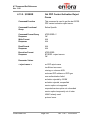
2.1.3.2.
AT+CREG
Command Function
Network Registration Info
Write command controls the presentation of
an unsolicited result code +CREG: <stat> .
Read command returns the status of result
code, which shows whether the network
has currently indicated the registration of
the ME.
Command Functional
Group
Network Information
Command Format Query
Response
AT+CREG=?
+CREG: (0,2)
OK
Write Format
Response
AT+CREG=[<n>]
OK
Read Format
Response
AT+CREG?
+CREG: <n>,<stat>[,<lac>,<ci>]
OK
Execution Format
Response
N/A
N/A
GSM1308AT001
Page 32
Ver. 1.00 – 10/29/2008
AT Command Set Reference
Ver. 1.00
2.1.3.2.
AT+CREG
Network Registration Info
(continued)
Parameter Values
<n>
0
1
2
<stat>
0
1
2
3
4
5
<lac>
<ci>
disable network registration
unsolicited result code
enable network registration
unsolicited result code +CREG:
<stat>
enable network registration and
location information unsolicited result
code +CREG: <stat>[,<lac>,<ci>]
not registered, ME is not currently
searching a new operator to
register to
registered, home network
not registered, but ME is currently
searching a new operator to
register to
registration denied
unknown
registered, roaming
string type; two-byte location area code in
hexadecimal format (e.g. "00C3" equals
195 in decimal)
string type; two-byte cell ID in hexadecimal
format
Reference
GSM Ref. 07.07 Chapter 7.2
Standard Scope
Optional
Enfora Implementation Scope Partial
Notes
GSM1308AT001
N/A
Page 33
Ver. 1.00 – 10/29/2008
AT Command Set Reference
Ver. 1.00
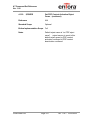
2.1.3.3.
AT+COPS
Command Function
Operator Selection
Write command forces an attempt to select
and register the GSM network operator.
<mode> is used to select whether the
selection is done automatically by the ME
or is forced by this command to operator
<oper> (it shall be given in format
<format>). If the selected operator is not
available, no other operator shall be
selected (except <mode> = 4). The
selected operator name format shall apply
to further read commands (+COPS?) also.
<mode>=2 forces an attempt to deregister
from the network. The selected mode
affects to all further registration (e.g. after
<mode>=2, ME shall be unregistered until
<mode>=0 or 1 is selected).
Read command returns the current mode
and the currently selected operator. If no
operator is selected, <format> and <oper>
are omitted.
Test command returns a list of quadruplets,
each representing an operator present in
the network. Quadruplet consists of an
integer indicating the availability of the
operator <stat>, long and short
alphanumeric format of the name of the
operator, and numeric format
representation of the operator. Any of the
formats may be unavailable and will then be
an empty field (,,). The list of operators
comes in the following order: Home
network, networks referenced in SIM, and
other networks.
Command Functional
Group
GSM1308AT001
Network Information
Page 34
Ver. 1.00 – 10/29/2008
AT Command Set Reference
Ver. 1.00
2.1.3.3.
AT+COPS
Operator Selection
(continued)
Command Format Query
Response
AT+COPS=?
+COPS: (2, “ “, “ “, “31022”), (3, “ “,
“ “, “310380”)
OK
Write Format
Response
AT+COPS=<mode>
[, <format> [, oper>]]
OK or
+CME ERROR: <err>
Read Format
Response
AT+COPS?
+COPS: 0
OK
Execution Format
Response
N/A
N/A
GSM1308AT001
Page 35
Ver. 1.00 – 10/29/2008
AT Command Set Reference
Ver. 1.00
2.1.3.3.
AT+COPS
Operator Selection
(continued)
Parameter Values
<mode>
0
automatic (<oper> field is ignored)
1
manual (<oper> field shall be
present)
deregister from network
set only <format> (for read
command +COPS?), do not attempt
registration/deregistration (<oper>
field is ignored); this value is not
applicable in read command
response
manual/automatic (<oper> field shall
be present); if manual selection fails,
automatic mode (<mode=0) is
entered
2
3
4
<format>
.
0
1
2
long format alphanumeric <oper>
short format alphanumeric <oper>
numeric <oper>; GSM Location
Area Identification Number
<oper>
operator in format as in per <format>
<stat>
0
1
2
3
Reference
GSM Ref. 07.07 Chapter 7.3
Standard Scope
Optional
Unknown
Available
Current
Forbidden
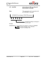
Enfora Implementation Scope Partial
Notes
GSM1308AT001
Page 36
Ver. 1.00 – 10/29/2008
AT Command Set Reference
Ver. 1.00
2.1.3.3.
AT+COPS
Operator Selection
(continued)
Example:
To manually register the modem on a known PLMN:
AT+COPS=1,2,”xxxxx”
PLMN
Numeric format
Manually register
To read operator information:
AT+COPS=?
+COPS: (2,”Voicestream”,”Vstream”,”31022”)
PLMN
Short format
Long format
State (current)
GSM1308AT001
Page 37
Ver. 1.00 – 10/29/2008
AT Command Set Reference
Ver. 1.00
2.1.3.4.
AT+CLCK
Facility Lock
Command Function
This command is used to lock, unlock or
interrogate a ME or a network facility <fac>.
When querying the status of a network
service (<mode>=2) the response line for a
“not active” case (<status=0>) should be
returned only if service is not active for any
<class>. Is should be possible to abort the
command when network facilities are set or
interrogated.
Command Functional
Group
Supplemental Services
Command Format Query
Response
AT+CLCK=?
+CLCK: (“SC”, “AO”, “OI”, “OX”, “AI”, “IR”,
“AB”, “AG”, “AC”, “FD”, "PC","PP", “PS”,
“PN”, “PU”, “PF”,”AL”)
OK
Write Format
AT+CLCK=<fac>, <mode> [,<passwd>
[, <class>]]
If <mode><> 2 and command is successful
then OK
Response
If <mode>=2 and command is successful
then
+CLCK:<status>,[,<class1>[<CR><LF>
+CLCK: <status>, class2…]]
OK
Read Format
Response
N/A
N/A
Execution Format
Response
N/A
N/A
GSM1308AT001
Page 38
Ver. 1.00 – 10/29/2008
AT Command Set Reference
Ver. 1.00
2.1.3.4.
AT+CLCK
Facility Lock
(continued)
Parameter Values
<fac>
“SC”
“AO”
“OI”
“OX”
“AI”
“IR”
“AB”
“AG”
“AC”
“FD”
"PC"
"PP"
"PS"
"PF"
"PN"
"PU"
"AL"
GSM1308AT001
Page 39
(SIM PIN 1)
(Barr All Outgoing Calls)
(Barr Outgoing International Calls)
(Barr Outgoing International Calls
except Home Country)
(Barr All Incoming Calls)
(Barr Incoming Calls when Roaming
outside the Home Country)
(All Barring Services)
(All Outgoing Barring)
(All incoming Barring)
(SIM Fixed Dialing Feature)
(Corporate Personalization, allows
personalization to custom corporate
group settings)
(Provider Personalization, allows for
personalization to custom service
provider defined groups)
PH-SIM (lock PHone to SIM card)
(ME asks password when other than
current SIM card inserted; ME may
remember
certain
amount
of
previously used cards thus not
requiring password when they are
inserted)
lock Phone to the very First inserted
SIM card (also referred in the
present document as PH-FSIM) (ME
asks password when other than the
first SIM card is inserted)
Network Personalisation (refer GSM
02.22 [33])
network
sUbset
Personalisation
(refer GSM 02.22 [33])
alternating Line service (PIN2)
Ver. 1.00 – 10/29/2008
AT Command Set Reference
Ver. 1.00
2.1.3.4.
AT+CLCK
Facility Lock
(continued)
<mode>
0
1
2
Unlock
Lock
Query Status
<password>
“password”
<class>
1
2
4
7
8
voice
data
fax (fax not supported)
all classes (default)
short message service
<status>
0
1
off
on
Reference
GSM Ref. 07.07 Chapter 7.4
Standard Scope
Optional
Enfora Implementation Scope Partial
Notes
Example:
To set Network Personalisation on first SIM inserted:
AT+CLCK=”PF”,1,”password”,,”PN”
Password
Lock
Lock module to very first SIM
inserted
To enable SIM PIN:
AT+CLCK=”SC”,1,”xxxx”
PIN
Enable
SIM PIN
GSM1308AT001
Page 40
Ver. 1.00 – 10/29/2008
AT Command Set Reference
Ver. 1.00
2.1.3.5.
AT+CPWD
Change Password
Command Function
This command is used to set a new
password for the facility lock function
defined by command Facility Lock +CLCK.
Command Functional
Group
Supplemental Services
Command Format Query
Response
AT+CPWD=?
+CPWD: (“SC”, “AD”, “OI”, “OX”, “AI”, “IR”,
“AB”, “AG”, “AC”, “P2”, “PC”, “PP”, “PS”,
“PN”, “PU”, “PF”)
OK
Write Format
AT+CPWD = <fac>, [<oldpwd>],
<newpwd>
OK or
+CME ERROR: <err>
Response
Read Format
Response
N/A
N/A
Execution Format
Response
N/A
N/A
GSM1308AT001
Page 41
Ver. 1.00 – 10/29/2008
AT Command Set Reference
Ver. 1.00
2.1.3.5.
AT+CPWD
Change Password
(continued)
Parameter Values
<fac>
GSM1308AT001
“SC” (SIM PIN 1)
“AO” (Barr All Outgoing Calls)
“OI” (Barr Outgoing International
Calls)
“OX” (Barr Outgoing International Calls
except Home Country)
“AI” (Barr All Incoming Calls)
“IR” (Barr Incoming Calls when Roaming
outside the Home Country)
“AB” (All Barring Services)
“AG” (All Outgoing Barring)
“AC” (All incoming Barring)
“P2” (SIM PIN 2)
"PC" (Corporate Personalization, allows
personalization to custom corporate
group settings)
"PP" (Provider Personalization, allows for
personalization to custom service
provider defined groups)
"PS" PH-SIM (lock PHone to SIM card)
(ME asks password when other than
current SIM card inserted; ME may
remember
certain
amount
of
previously used cards thus not
requiring password when they are
inserted)
"PF" lock Phone to the very First inserted
SIM card (also referred in the
present document as PH-FSIM) (ME
asks password when other than the
first SIM card is inserted)
"PN" Network Personalisation (refer GSM
02.22 [33])
"PU" network
sUbset
Personalisation
(refer GSM 02.22 [33])
Page 42
Ver. 1.00 – 10/29/2008
AT Command Set Reference
Ver. 1.00
2.1.3.5.
AT+CPWD
Change Password
(continued)
<oldpwd>
Password specified for the facility. If an old
password has not yet been set, <oldpwd>
is not entered
<newpwd>
“new password”
Reference
Standard Scope
GSM Ref. 07.07 Chapter 7.5
Optional
Enfora Implementation Scope Partial
Notes
In order to change the password, the
applicable facility must be enabled. See
AT+CLCK.
Example:
Enter first password for Network Personalisation:
AT+CPWD=”PN”,,”xxxx”
Password for Network Personalisation
Network Personalisation
To change SIM PIN:
AT+CPWD=”SC”,”xxxx”,”yyyy”
New password
Old password
SIM PIN
GSM1308AT001
Page 43
Ver. 1.00 – 10/29/2008
AT Command Set Reference
Ver. 1.00
2.1.3.6.
AT+CLIP
Calling Line Identification Presentation
Command Function
This command refers to the GSM
supplementary service CLIP (Calling Line
Identification Presentation) that enables a
called subscriber to get the Calling Line
Identity (CLI) of the calling party when
receiving a mobile terminated call. The
write command enables or disables the
presentation of the CLI at the TE. It has no
effect on the execution of the
supplementary service CLIP in the network.
Command Functional
Group
Supplementary Services
Command Format Query
Response
AT+CLIP=?
+CLIP: (0, 1)
OK
Write Format
Response
AT+CLIP=<n>
+CLIP: <n> or
OK or
+CME ERROR: <err>
Read Format
Response
AT+CLIP?
+CLIP: <n>, <m>
OK
Execution Format
Response
N/A
N/A
GSM1308AT001
Page 44
Ver. 1.00 – 10/29/2008
AT Command Set Reference
Ver. 1.00
2.1.3.6.
AT+CLIP
Unsolicited Result Code
Calling Line Identification
Presentation (continued)
When CLIP is enabled at the TE (and is
permitted by the calling subscriber), an
unsolicited result code is returned after the
first RING (or +CRING: <type>) at a mobile
terminating call
Voice call response format:
+CLIP: <number>, <type>,,,,<CLI
validity>
Data/FAX call response format:
+CLIP: <number>, <type>
Parameter Values
<n>
0
1
suppress unsolicited results
codes
display unsolicited result codes
<m>
0
1
2
CLIP not enabled
CLIP enabled
Unknown
<number>
string type phone number of calling
address in format specified by <type>
<type>
type of address octet in integer format: 145
when dialing string includes international
access code character “+”, otherwise 129
<CLI validity>
0
1
3
GSM1308AT001
Page 45
CLI valid
CLI has been withheld by the
originator
CLI is not available due to interworking problems or limitations of
originating network. <number> shall
be an empty string (“”) and <type>
value will not be significant.
Ver. 1.00 – 10/29/2008
AT Command Set Reference
Ver. 1.00
2.1.3.6.
AT+CLIP
Calling Line Identification
Presentation (continued)
Reference
GSM Ref. 07.07 Chapter 7.6
Standard Scope
Optional
Enfora Implementation Scope Full
Notes
GSM1308AT001
N/A
Page 46
Ver. 1.00 – 10/29/2008
AT Command Set Reference
Ver. 1.00
2.1.3.7.
AT+CLIR
Command Function
Calling Line Identification Restriction
This command allows a calling subscriber
to enable or disable the presentation of the
CLI to the called party when originating a
call.
The write command overrides the CLIR
subscription (default is restricted or
allowed) when temporary mode is
provisioned as a default adjustment for all
outgoing calls. This adjustment can be
revoked by using the opposite command.
This command, when used by a subscriber,
without provision of CLIR in permanent
mode the network will act according GSM
02.81 [3].
The read command gives the default
adjustment for all outgoing calls (given in
<n>), and also triggers and interrogation of
the provision status of the CLIR service
(given in <m>).
Command Functional
Group
Supplementary Services
Command Format Query
Response
AT+CLIR=?
+CLIR: (0, 1, 2)
OK
Write Format
Response
AT+CLIR=[<n>]
N/A
Read Format
Response
AT+CLIR?
+CLIR: <n>, <m>
OK
Execution Format
Response
N/A
N/A
GSM1308AT001
Page 47
Ver. 1.00 – 10/29/2008
AT Command Set Reference
Ver. 1.00
2.1.3.7.
AT+CLIR
Calling Line Identification
Restriction (continued)
Parameter Values
<n>
(parameter sets the adjustment for outgoing
calls)
0 presentation indicator is used according
to the subscription of the CLIR service
1 CLIR Invocation
2 CLIR suppression
<m>
(parameter shows the subscriber CLIR
service status in the network)
0
1
2
3
CLIR not enabled
CLIR enabled in permanent mode
Unknown (e.g. no network, etc.)
CLIR temporary mode presentation
restricted
4 CLIR temporary mode presentation
allowed
Reference
GSM Ref. 07.07 Chapter 7.7
Standard Scope
Optional
Enfora Implementation Scope Fully
Notes
GSM1308AT001
N/A
Page 48
Ver. 1.00 – 10/29/2008
AT Command Set Reference
Ver. 1.00
2.1.3.8.
AT+COLP
Connected Line Identification
Presentation
Command Function
This command is enables a calling
subscriber to get the Connected Line
Identity (COL) of the called party after
setting up a mobile originated call. The
command enables or disables the
presentation of the COL at the TE. It has
no effect on the execution of the
supplementary service COLR in the
network.
Command Functional
Group
Supplementary Services
Command Format Query
Response
AT+COLP=?
+COLP: (0, 1)
OK
Write Format
Response
AT+COLP= [<n>]
OK
Read Format
Response
AT+COLP?
+COLP: <n>, <m>
OK
Execution Format
Response
N/A
N/A
GSM1308AT001
Page 49
Ver. 1.00 – 10/29/2008
AT Command Set Reference
Ver. 1.00
2.1.3.8.
AT+COLP
Connected Line Identification
Presentation (continued)
Parameter Values
<n>
(parameter sets/shows the result code
presentation status in the TA)
0
1
<m>
disable
enable
(parameter shows the subscriber COLP
0
1
2
COLP not enabled
COLP enabled
Unknown (e.g. no network, etc.)
Reference
GSM Ref. 07.07 Chapter 7.8
Standard Scope
Optional
Enfora Implementation Scope Full
Notes
GSM1308AT001
N/A
Page 50
Ver. 1.00 – 10/29/2008
AT Command Set Reference
Ver. 1.00
2.1.3.9.
AT+CCUG
Command Function
Closed User Group
This command allows control of the Closed
User Group supplementary service.
Write command with <n>=1 enables to
control the CUG information on the air
interface as a default adjustment for all
following outgoing calls.
Command Functional
Group
Supplementary Services
Command Format Query
Response
AT+CCUG=?
+CCUG: (0, 1), (0,-10), (0-3)
OK
Write Format
Response
AT+CCUG= [<n> [,<index> [,<info>] ] ]
N/A
Read Format
Response
AT+CCUG?
+CCUG: 0, 0, 0
OK
Execution Format
Response
N/A
N/A
Parameter Values
<n>
0
1
disable CUG temporary mode
enable CUG temporary mode
<index>
0-9
10
CUG index
no index preferred CUG taken from
subscriber data)
<info>
0
1
2
3
no information
suppress OA
suppress preferential CUG
suppress OA and preferential CUG
GSM1308AT001
Page 51
Ver. 1.00 – 10/29/2008
AT Command Set Reference
Ver. 1.00
2.1.3.9.
AT+CCUG
Closed User Group
(continued)
Reference
GSM Ref. 07.07 Chapter 7.9
Standard Scope
Optional
Enfora Implementation Scope Full
Notes
GSM1308AT001
N/A
Page 52
Ver. 1.00 – 10/29/2008
AT Command Set Reference
Ver. 1.00
2.1.3.10.
AT+CCFC
Call Forwarding Number and Condition
Command Function
This command allows control of the call
forwarding supplementary service.
Registration erasure, activation,
deactivation, and status query are
supported. When querying the status of a
network service (<mode> = 2), the
response line for “not active” (<status> = 0)
should be returned only if service is not
active for any <class>.
Command Functional
Group
Supplementary Services
Command Format Query
Response
AT+CCFC=?
+CCFC: (0-5)
OK
Write Format
Response
N/A
N/A
Read Format
Response
N/A
N/A
Execution Format
AT+CCFC=<reas>, <mode> [,
<number>[,<type> [, <class> [,<time>]]]]
If <mode> <> 2 and command successful
OK
Response
If <mode> = 2 and command successful
(only in connection with <reason> 03)
+CCFC: <status>,
<class1>[,<number>,<type>[,<time>]]
[<CR><LF>+CCFC: ….] OK
If error is related to ME functionality:
+CME ERROR: <err>
GSM1308AT001
Page 53
Ver. 1.00 – 10/29/2008
AT Command Set Reference
Ver. 1.00
2.1.3.10.
AT+CCFC
Call Forwarding Number and
Conditions (continued)
Parameter Values
<reas>
0
1
2
3
4
5
unconditional
mobile busy
no reply
not reachable
all call forwarding
all conditional call forwarding
<mode>
0
1
2
3
4
disable
enable
query status
registration
erasure
<number>
string type phone number of forwarding
address in format specified by <type>
<type>
type of address in integer format; default
145 when dialing string includes
international access code character “+”,
otherwise 129
<class>
1
2
4
8
16
32
voice
data
fax (fax not supported)
short message service
data circuit sync
data circuit async
<subaddr>
string type subaddress of format specified
by <satype>
<satype>
type of subaddress octet in integer format
(refer GSM 04.08 [8] subclause 10.5.4.8);
default 128
GSM1308AT001
Page 54
Ver. 1.00 – 10/29/2008
AT Command Set Reference
Ver. 1.00
2.1.3.10.
AT+CCFC
Call Forwarding Number and
Conditions (continued)
<time>
time to wait before call is forwarded,
rounded to a multiple of 5 sec
Default is 20.
1…20..30 (only for <reas>=no reply)
<status>
0
1
Reference
GSM Ref. 07.07 Chapter 7.10
Standard Scope
Optional
not active
active
Enfora Implementation Scope Full
Notes
Example:
To call forward all voice calls, no reply after five seconds:
AT+CCFC=2,1,”+1719xxxxxx”,145,1,,,5
Forward after 5 seconds
All Voice calls
International number type
Forward to this number
Enable forwarding
No reply
GSM1308AT001
Page 55
Ver. 1.00 – 10/29/2008
AT Command Set Reference
Ver. 1.00
2.1.3.11.
AT+CCWA
Call Waiting
Command Function
This command allows control of the Call
Waiting supplementary service. Activation
and deactivation are supported.
Command Functional
Group
Results
Command Format Query
Response
AT+CCWA=?
+CCWA: (0,1)
OK
Write Format
Response
AT+CCWA=<n>,<mode>,<class>
OK
Read Format
Response
AT+CCWA?
+CCWA: 0
OK
Execution Format
Response
N/A
N/A
Parameter Values
<n>
Sets/shows results code presentation in TA
0
1
Disable
Enable
<mode>
0
1
2
Disable
Enable
Query status
<class>
1
2
4
Voice
Data
Fax (fax not supported)
Reference
GSM Ref. 07.07 Chapter 7.11
Standard Scope
Optional
Enfora Implementation Scope Partial
GSM1308AT001
Page 56
Ver. 1.00 – 10/29/2008
AT Command Set Reference
Ver. 1.00
2.1.3.11.
AT+CCWA
Notes
Call Waiting
(continued)
Not all networks support call waiting for
data and fax. Please contact service
provider for details.
Example:
AT+CCWA=1,1,1
Voice
Enable Call Waiting
Enable Result Codes
GSM1308AT001
Page 57
Ver. 1.00 – 10/29/2008
AT Command Set Reference
Ver. 1.00
2.1.3.12.
AT+CHLD
Call Hold and Multiparty
Command Function
This command controls the supplementary
services Call Hold, MultiParty and Explicit
Call
Transfer. Calls can be put on hold,
recovered, released, added to conversation
and transferred.
Command Functional
Group
Supplementary Services
Command Format Query
Response
AT+CHLD=?
+CHLD: (0, 1, 1x, 2, 2x, 3, 4)
OK
Write Format
Response
N/A
N/A
Read Format
Response
N/A
N/A
Execution Format
Response
AT+CHLD=<n>
OK
GSM1308AT001
Page 58
Ver. 1.00 – 10/29/2008
AT Command Set Reference
Ver. 1.00
2.1.3.12.
AT+CHLD
Call Hold and Multiparty
(continued)
Parameter Values
<n>
0
1
1X
2
2X
3
4
Terminate all held calls; or set UDUB
(User Determined User Busy) for a
waiting call, i.e. reject the waiting
call.
Terminate all active calls (if any) and
accept the other call (waiting call or
held call)
Terminate the active call X (X= 1-7)
Place all active calls on hold (if any)
and accept the other call
(waiting call or held call) as the
active call
Place all active calls except call X
(X= 1-7) on hold
Add the held call to the active calls
Connects the two calls and
disconnects the subscriber from both
calls (ECT).
Reference
GSM Ref. 07.07 Chapter 7.12
Standard Scope
Optional
Enfora Implementation Scope Full
Notes
GSM1308AT001
Call Hold, MultiParty and Explicit Call
Transfer are only applicable to
teleservice 11(Speech Telephony).
Page 59
Ver. 1.00 – 10/29/2008
AT Command Set Reference
Ver. 1.00
2.1.3.13.
AT+CUSD
Unstructured Supplementary Service
Command Function
This command allows control of the
Unstructured Supplementary Service Data
(USSD)]. Both network and mobile initiated
operations are supported. Parameter <n>
is used to disable/enable the presentation
of an unsolicited result code (network
initiated operation) to the TE.
Command Functional
Group
Supplementary Services
Command Format Query
Response
AT+CUSD=?
+CUSD: (0, 1, 2)
OK
Write Format
Response
+CUSD=[<n>[,<str>[,<dcs>]]]
OK
Read Format
Response
AT+CUSD?
+CUSD: 0
OK
Execution Format
Response
N/A
N/A
Parameter Values
<n>
0
1
2
disable the result code
presentation
enable the result code presentation
cancel session
(when <str> parameter is not given,
network is not interrogated)
<str>
actual USSD string in “quotes”
<dcs>
language parameter see GSM 03.38
- Default 15 (Language unspecified)
Reference
GSM Ref. 07.07 Chapter 7.14
GSM Ref. 03.38 Chapter 5
GSM1308AT001
Page 60
Ver. 1.00 – 10/29/2008
AT Command Set Reference
Ver. 1.00
2.1.3.13.
AT+CUSD
Standard Scope
Unstructured Supplementary Service
(continued)
Optional
Enfora Implementation Scope Full
Notes
Example
AT+CUSD=1,"*201*35#",15
OK
+CUSD: 0,"*201*35#",15 (network response)
USSD stings can also be sent using the ATD command.
ATD*201*35#
OK
+CUSD: 0,"*201*35#",15 (network response)
GSM1308AT001
Page 61
Ver. 1.00 – 10/29/2008
AT Command Set Reference
Ver. 1.00
2.1.3.14.
AT+CAOC
Advice of Charge
Command Function
This refers to Advice of Charge
supplementary service that enables
subscriber to get information about the cost
of calls. With <mode>=0, the execute
command returns the current call meter
value from the ME.
Command Functional
Group
Supplementary Services
Command Format Query
Response
AT+CAOC=?
+CAOC: (0-2)
OK
Write Format
Response
AT+CAOC=<mode>
Read Format
Response
AT+CAOC?
+CAOC: 1
OK
Execution Format
Response
AT+CAOC
+CAOC: “000000”
OK
Parameter Values
<mode>
0
1
2
Query CCM value
Deactivate
Activate
Reference
GSM Ref. 07.07 Chapter 7.15
Standard Scope
Optional
Enfora Implementation Scope Full
Notes
GSM1308AT001
When <mode>=0, execution command will
return the current call meter value.
Page 62
Ver. 1.00 – 10/29/2008
AT Command Set Reference
Ver. 1.00
2.1.3.15.
AT+CSSN
Command Function
Supplementary Service Notifications
This command refers to supplementary
service related network initiated
notifications. The set command
enables/disables the presentation of
notification result codes from TA to TE.
When <n>=1 and a supplementary service
notification is received after a mobile
originated call setup, intermediate result
code +CSSI: <code1>[,<index>] is sent to
TE before any other MO call setup result
codes are presented. When several
different <code1>s are received from the
network, each of them shall have its own
+CSSI result code.
When <m>=1 and a supplementary service
notification is received during a mobile
terminated call setup or during a call; or
when a forward check supplementary
service notification is received, unsolicited
result code +CSSU:
<code2>[,<index>[,<number>,<type>[,<s
ubaddr>,<satype>]]] is sent to TE. In case
of MT call setup, result code is sent after
every +CLIP result code (refer command
"Calling line identification presentation
+CLIP"). When several different <code2>s
are received from the network, each of
them shall have its own +CSSU result code.
GSM1308AT001
Page 63
Ver. 1.00 – 10/29/2008
AT Command Set Reference
Ver. 1.00
2.1.3.15.
AT+CSSN
Supplementary Service Notifications
(continued)
Command Functional
Group
Supplementary Services
Command Format Query
Response
AT+CSSN=?
+CSSN: (0, 1), (0, 1)
OK
Write Format
Response
AT+CSSN=<n>, <m>
OK
Read Format
Response
AT+CSSN?
+CSSN: <n>, <m>
OK
Execution Format
Response
N/A
N/A
Parameter Values
<n>
(parameter sets/shows the +CSSI result
code presentation status in the TA):
0
disable
1
enable
<m>
(parameter sets/shows the +CSSU result
code presentation status in the TA):
0
disable
1
enable
<code1>
0
1
2
3
4
5
6
7
8
GSM1308AT001
Page 64
unconditional call forwarding is
active
some of the conditional call
forwardings are active
call has been forwarded
call is waiting
this is a CUG call (also <index>
present)
outgoing calls are barred
incoming calls are barred
CLIR suppression rejected
call has been deflected
Ver. 1.00 – 10/29/2008
AT Command Set Reference
Ver. 1.00
2.1.3.15.
AT+CSSN
Supplementary Service Notifications
(continued)
<index>
refer "Closed user group +CCUG"
<code2>
0
1
2
3
4
5
6
7
8
9
this is a forwarded call (MT call
setup)
this is a CUG call (also <index>
present) (MT call setup)
call has been put on hold (during a
voice call)
call has been retrieved (during a voice
call)
multiparty call entered (during a voice
call)
call on hold has been released (this is
not a SS notification) (during a voice
call)
forward check SS message received
(can be received whenever)
call is being connected (alerting) with
the remote party in alerting state in
explicit call transfer operation (during
a voice call)
call has been connected with the other
remote party in explicit call transfer
operation (also number and
subaddress parameters may be
present) (during a voice call or MT call
setup)
this is a deflected call (MT call setup)
<number>
string type phone number of format
specified by <type>
<type>
type of address octet in integer format
<subaddr>
string type subaddress of format specified
by <satype>
<satype>
type of subaddress octet in integer format
GSM1308AT001
Page 65
Ver. 1.00 – 10/29/2008
AT Command Set Reference
Ver. 1.00
2.1.3.15.
AT+CSSN
Supplementary Service Notifications
(continued)
Reference
GSM Ref. 07.07 Chapter 7.16
Standard Scope
Optional
Enfora Implementation Scope Full
Notes
GSM1308AT001
N/A
Page 66
Ver. 1.00 – 10/29/2008
AT Command Set Reference
Ver. 1.00
2.1.3.16.
AT+CLCC
List current calls
Command Function
Returns list of current calls of ME. If
command succeeds but no calls are
available, no information response is sent
to TE.
Command Functional
Group
Call Control
Command Format Query
Response
AT+CLCC=?
OK
Write Format
Response
N/A
N/A
Read Format
Response
N/A
N/A
Execution Format
Response
AT+CLCC
[+CLCC: <id1>,<dir>,<stat>,
<mode>,<mpty>[,<number>,
<type>[,<alpha>]]
[<CR><LF>+CLCC: <id2>,<dir>,
<stat>,<mode>,<mpty>
[,<number>,<type>[,<alpha>]]
[...]]]
OK
Parameter Values
<idx>
integer type; call identification number as
described in GSM 02.30 [19] subclause
4.5.5.1; this number can be used in +CHLD
command operations
<dir>
0
1
GSM1308AT001
Page 67
mobile originated (MO) call
mobile terminated (MT) call
Ver. 1.00 – 10/29/2008
AT Command Set Reference
Ver. 1.00
2.1.3.16.
AT+CLCC
List current calls
(continued)
<stat>
(state of the call):
0
active
1
held
2
dialling (MO call)
3
alerting (MO call)
4
incoming (MT call)
5
waiting (MT call)
<mode>
(bearer/teleservice):
0
voice
1
data
2
fax (fax not supported)
3
voice followed by data, voice mode
4
alternating voice/data, voice mode
5
alternating voice/fax, voice mode
6
voice followed by data, data mode
7
alternating voice/data, data mode
8
alternating voice/fax, fax mode
9
unknown
<mpty>
0
1
call is not one of multiparty
(conference) call parties
call is one of multiparty
(conference) call parties
<number>
string type phone number in format
specified by <type>
<type>
type of address octet in integer format (refer
GSM 04.08 [8] subclause 10.5.4.7)
<alpha>
string type alphanumeric representation of
<number> corresponding to the entry found
in phonebook; used character set should be
the one selected with command Select TE
Character Set +CSCS
GSM1308AT001
Page 68
Ver. 1.00 – 10/29/2008
AT Command Set Reference
Ver. 1.00
2.1.3.16.
AT+CLCC
List current calls
(continued)
Reference
GSM Ref. 07.07 Chapter 7.17
Standard Scope
Optional
Enfora Implementation Scope Full
Notes
GSM1308AT001
N/A
Page 69
Ver. 1.00 – 10/29/2008
AT Command Set Reference
Ver. 1.00
2.1.3.17.
AT+CPOL
Preferred Operator list
Command Function
This command is used to list and edit the
SIM preferred list of networks.
Command Functional
Group
Network
Command Format Query
Response
AT+CPOL=?
+CPOL: (1-n), (0-2)
OK
Write Format
Response
AT CPOL=[<index>][, <format>[,<oper>]]
OK
Read Format
Response
AT+CPOL?
+CPOL: <index1>,<format>,<oper1>…
<index10>,<format>,<oper10>
OK
Execution Format
Response
N/A
N/A
Parameter Values
<indexn>:
integer type; the order number of operator
in the SIM preferred operator list
<format>:
0
1
2
<opern>:
long format alphanumeric <oper>
short format alphanumeric <oper>
numeric <oper>
string type; <format> indicates if the format
is alphanumeric or numeric (see +COPS)
Reference
GSM Ref. 07.07 Chapter 7.18
Standard Scope
Optional
Enfora Implementation Scope Full
GSM1308AT001
Page 70
Ver. 1.00 – 10/29/2008
AT Command Set Reference
Ver. 1.00
2.1.3.17.
Notes
GSM1308AT001
AT+CPOL
Preferred Operator list
(continued)
This command is used to edit the SIM
preferred list of networks. Execute
command writes an entry in the SIM list of
preferred operators (EFPLMNsel). If <index>
is given but <oper> is left out, entry is
deleted. If <oper> is given but <index> is
left out, <oper> is put in the next free
location. If only <format> is given, the
format of the <oper> in the read command
is changed.
Page 71
Ver. 1.00 – 10/29/2008
AT Command Set Reference
Ver. 1.00
2.1.3.18.
AT+COPN
Read Operator Names
Command Function
Execute command returns the list of
operator names from the ME.
Command Functional
Group
Network
Command Format Query
Response
N/A
N/A
Write Format
Response
N/A
N/A
Read Format
Response
N/A
N/A
Execution Format
Response
AT+COPN
+COPN: <numeric1>,<alpha1>
[<CR><LF>+COPN: <numeric2>,
<alpha2>[...]]
OK
Parameter Values
<numericn>
string type; operator in numeric format (see
+COPS)
<alphan>
string type; operator in long alphanumeric
format (see +COPS)
Reference
GSM Ref. 07.07 Chapter 7.19
Standard Scope
Optional
Enfora Implementation Scope Full
Notes
GSM1308AT001
N/A
Page 72
Ver. 1.00 – 10/29/2008
AT Command Set Reference
Ver. 1.00
2.1.4. ME Control and Status Commands
2.1.4.1.
AT+CPAS
Phone Activity Status
Command Function
Execution command returns the activity
status <pas> of the ME. It can be used to
interrogate the ME before requesting action
from the phone. Test command returns
values supported by the ME as a
compound value.
Command Functional
Group
Phone Control
Command Format Query
Response
AT+CPAS=?
+CPAS: (0-5) or
+CME ERROR: <err>
OK
Write Format
Response
N/A
N/A
Read Format
Response
N/A
N/A
Execution Format
Response
AT+CPAS
AT+CPAS: <pas>
OK
GSM1308AT001
Page 73
Ver. 1.00 – 10/29/2008
AT Command Set Reference
Ver. 1.00
2.1.4.1.
AT+CPAS
Phone Activity Status
(continued)
Parameter Values
<pas>
0
1
2
3
4
5
Ready (ME allows commands
from TA/TE)
Unavailable (ME does not allow
commands from TA/TE)
Unknown (ME is not guaranteed to
respond to instructions)
Ringing (ME is ready for commands
from TA/TE, but the ringer is active)
Call in progress (ME is ready for
commands from TA/TE, but a call is
in progress)
Asleep (ME is unable to process
commands from TA/TE because it is
in a low functionality state)
Reference
GSM Ref. 07.07 Chapter 8.1
Standard Scope
Optional
Enfora Implementation Scope Full
Notes
GSM1308AT001
N/A
Page 74
Ver. 1.00 – 10/29/2008
AT Command Set Reference
Ver. 1.00
2.1.4.2.
AT+CFUN
Set Phone Functionality
Command Function
Set command selects the level of
functionality <fun> in the ME. Level "full
functionality" is where the highest level of
power is drawn. "Minimum functionality" is
where minimum power is drawn.
Command Functional
Group
Phone Control
Command Format Query
Response
AT+CFUN=?
+CFUN: (0,1,4), (0)
OK
Write Format
Response
AT+CFUN=<fun>,<rst>
OK
Read Format
Response
AT+CFUN?
+CFUN: 1
OK
Execution Format
Response
N/A
N/A
Parameter Values
<fun>
0
1
4
Minimum functionality
Full functionality
disable phone both transmit and
receive RF circuits
<rst>
0
Do not reset ME
Reference
GSM Ref. 07.07 Chapter 8.2
Standard Scope
Optional
Enfora Implementation Scope Partial
Notes
GSM1308AT001
Once the modem has left the minimum
functionality state, it will respond to
AT+CFUN? with +CFUN: 1 regardless of
whether the modem has reached full
functionality yet.
Page 75
Ver. 1.00 – 10/29/2008
AT Command Set Reference
Ver. 1.00
2.1.4.3.
AT+CPIN
Enter PIN
Command Function
Set command sends to the ME a password
that is necessary before it can be operated
(SIM PIN, SIM PUK, PH-SIM PIN, etc.). If
no PIN request is pending, no action is
taken towards ME and an error message,
+CME ERROR, is returned to TE. If the
PIN required is SIM PUK or SIM PUK2, the
second pin is required. This second pin,
<newpin>, issued to replace the old pin in
the SIM.
Command Functional
Group
Phone Control
Command Format Query
Response
AT+CPIN=?
OK
Write Format
Response
AT+CPIN=<”pin”>,[<”newpin”>]
Read Format
Response
AT+CPIN?
+CPIN: <code>
OK
or
+CME ERROR: <err>
Execution Format
Response
N/A
N/A
Parameter Values
<code>
GSM1308AT001
READY
ME is not pending
for any password
SIM PIN
ME is waiting SIM PIN to be
given
SIM PUK
ME is waiting SIM PUK to be
given
PH-SIM PIN ME is waiting phone-to-SIM
card password to be given
Page 76
Ver. 1.00 – 10/29/2008
AT Command Set Reference
Ver. 1.00
2.1.4.3.
AT+CPIN
Enter PIN
(continued)
PH-FSIM PIN
ME is waiting phone-to-very
first SIM card password to be
given
PH-FSIM PUK
ME is waiting phone-to-very
first SIM card unblocking
password to be given
SIM PIN2
ME is waiting SIM PIN2 to be
given (this <code> is
recommended to be returned
only when the last executed
command resulted in PIN2
authentication failure (i.e.
+CME ERROR: 17); if PIN2 is
not entered right after the
failure, it is recommended that
ME does not block its
operation)
SIM PUK2
ME is waiting SIM PUK2 to be
given (this <code> is
recommended to be returned
only when the last executed
command resulted in PUK2
authentication failure (i.e.
+CME ERROR: 18); if PUK2
and new PIN2 are not entered
right after the failure, it is
recommended that ME does
not block its operation)
PH-NET PIN
ME is waiting network
personalization password to
be given
GSM1308AT001
Page 77
Ver. 1.00 – 10/29/2008
AT Command Set Reference
Ver. 1.00
2.1.4.3.
AT+CPIN
Enter PIN
(continued)
PH-NET PUK
ME is waiting network
personalization unblocking
password to be given
PH-NETSUB PIN
ME is waiting network subset
personalization password to
be given
PH-NETSUB PUK
ME is waiting network subset
personalization unblocking
password to be given
PH-SP PIN
ME is waiting service provider
personalization password to
be given
PH-SP PUK
ME is waiting service provider
personalization unblocking
password to be given
PH-CORP PIN
ME is waiting corporate
personalization password to
be given
PH-CORP PUK
ME is waiting corporate
personalization unblocking
password to be given
GSM1308AT001
Page 78
Ver. 1.00 – 10/29/2008
AT Command Set Reference
Ver. 1.00
2.1.4.3.
AT+CPIN
Enter PIN
(continued)
Reference
GSM Ref. 07.07 Chapter 8.3
Standard Scope
Optional
Enfora Implementation Scope Full
Notes Commands which interact with ME
that are accepted when ME is pending SIM
PIN,SIM PUK, or PH-SIM are: +CGMI,
+CGMM, +CGMR, +CGSN, D112;
(emergency call),+CPAS, +CFUN, +CPIN,
After power on the modem needs 20-25
seconds to initialize and completely read
the SIM.
* If AT$AREG=1, and PIN is enabled, the
modem will not complete the auto
registration process until after the PIN
has been entered (AT+CPIN).
GSM1308AT001
Page 79
Ver. 1.00 – 10/29/2008
AT Command Set Reference
Ver. 1.00
2.1.4.4.
AT+CSQ
Signal Quality and Bit Error Rate
Command Function
Execution command returns received signal
strength indication <rssi> and channel bit
error rate <ber> from the ME.
Command Functional
Group
Phone Control
Command Format Query
Response
AT+CSQ=?
+CSQ: (2-31,99),(99)
OK
Write Format
Response
N/A
N/A
Read Format
Response
N/A
N/A
Execution Format
Response
AT+CSQ
+CSQ: <rssi>, <ber>
OK
Parameter Values
<rssi>
<ber>
(in percent)
0
1
2-30
31
99
-113 dBm or less
-111 dBm
-109... -53 dBm
-51 dBm or greater
not known or not detectable
0-7
as RXQUAL values in the table in
GSM 05.08 [20] subclause 8.2.4
99
not known or not detectable
Reference
GSM Ref. 07.07 Chapter 8.5
Standard Scope
Optional
Enfora Implementation Scope Partial
Notes
GSM1308AT001
N/A
Page 80
Ver. 1.00 – 10/29/2008
AT Command Set Reference
Ver. 1.00
2.1.4.5.
AT+CPBS
Select Phonebook Memory Storage
Command Function
Set command enables or disables sending
of unsolicited result codes from TA to TE in
the case of key pressings, display changes,
and indicator state changes.
Command Functional
Group
Phonebook Control
Command Format Query
Response
AT+CPBS=?
+CPBS:
("EN","BD","FD","DC","LD","RC","LR","MT",
"AD","SM","SD","MC","LM","ON","UD")
OK
Write Format
Response
AT+CPBS=<storage>
OK
Read Format
Response
AT+CPBS?
+CPBS: <storage>, <used>, <total>
OK
Execution Format
Response
N/A
N/A
GSM1308AT001
Page 81
Ver. 1.00 – 10/29/2008
AT Command Set Reference
Ver. 1.00
2.1.4.5.
AT+CPBS
Select Phonebook Memory Storage
(continued)
Parameter Values
<storage>
"EN"
"FD"
"LD"
"BD"
"SD"
“DC”
“RC”
"LR"
“MT”
"AD"
"LM"
“MC”
"SM"
“ON”
“UD”
SIM (or ME) emergency number
SIM fixed-dialing-phonebook
SIM last-dialing-phonebook
SIM barred-dialing phonebook
SIM service numbers
MT dialed calls list
MT received calls list
Last received numbers (nonstandard)
combined MT and SIM/UICC phonebook
Abbreviated dialing numbers (nonstandard)
Last missed numbers (nonstandard)
MT missed (unanswered received) calls list
comb. of fixed and abbrev. dialing
phonebook (nonstandard)
active application in the UICC (GSM or
USIM) or SIM card (or MT) own numbers
(MSISDNs) list
User defined
<used>
integer type value indicating the number of
used locations in selected memory
<total>
integer type value indicating the total
number of locations in selected memory
Reference
GSM Ref. 07.07 Chapter 8.11
Standard Scope
Optional
Enfora Implementation Scope Partial
Notes
GSM1308AT001
To read the storage facilities, the correct
storage must be written to first and then
read.
Page 82
Ver. 1.00 – 10/29/2008
AT Command Set Reference
Ver. 1.00
2.1.4.5.
AT+CPBS
Select Phonebook Memory Storage
(continued)
Example:
AT+CPBS=”EN”
Enable Emergency number storage
AT+CPBS?
+CPBS: “EN”, 5,5
Total Number of locations in selected memory
Number of used locations in selected memory
Emergency number storage enabled
GSM1308AT001
Page 83
Ver. 1.00 – 10/29/2008
AT Command Set Reference
Ver. 1.00
2.1.4.6. AT+CPBR
Read Phonebook Entries
Command Function
Execution command returns phonebook
entries in location number range
<index1>... <index2> from the current
phonebook memory storage selected with
+CPBS. If <index2> is left out, only
location <index1> is returned.
Command Functional
Group
Phonebook Control
Command Format Query
Response
AT+CPBR=?
+CPBR: (1-250), 44,16
OK
Write Format
Response
N/A
N/A
Read Format
Response
N/A
N/A
Execution Format
Response
AT+CPBR=<index1>,<index2>,…
+CPBR: <index1>,<number>,
<type>,<text>
OK
GSM1308AT001
Page 84
Ver. 1.00 – 10/29/2008
AT Command Set Reference
Ver. 1.00
2.1.4.6.
AT+CPBR
Read Phonebook Entries
(continued)
Parameter Values
<index1>, <index2>, <index>
integer type values in the range of location
numbers of phonebook memory
<number>
string type phone number of format <type>
<type>
type of address octet in integer format
<text>
string type field of maximum length
<tlength>; character set as specified by
command Select TE Character Set +CSCS
<nlength>
integer type value indicating the maximum
length of field <number>
<tlength>
integer type value indicating the maximum
length of field <text>
Reference
GSM Ref. 07.07 Chapter 8.12
Standard Scope
Optional
Enfora Implementation Scope Full
Notes
GSM1308AT001
This command will read the storage facility
that is set with AT+CPBS.
Page 85
Ver. 1.00 – 10/29/2008
AT Command Set Reference
Ver. 1.00
2.1.4.7.
AT+CPBF
Find Phonebook Entries
Command Function
Execution command returns phonebook
entries (from the current phonebook
memory storage selected with +CPBS)
which alphanumeric field start with string
<findtext>.
Command Functional
Group
Phonebook Control
Command Format Query
Response
AT+CPBF=?
+CPBF: <nlength>, <tlength>
OK
Write Format
Response
N/A
N/A
Read Format
Response
N/A
N/A
Execution Format
Response
AT+CPBF=<”findtext”>
+CPBF: <index1>, <number>,
<type>,<text><CR><LF>+CBPF:
<index2>,<number>,<type>,<text>…
OK
GSM1308AT001
Page 86
Ver. 1.00 – 10/29/2008
AT Command Set Reference
Ver. 1.00
2.1.4.7.
AT+CPBF
Find Phonebook Entries
(continued)
Parameter Values
<index1>, <index2>
integer type values in the range of location
numbers of phonebook memory
<number>
string type phone number of format <type>
<type>
type of address octet in integer format
<findtext>, <text>
string type field of maximum length
<tlength>; character set as specified by
command Select TE Character Set +CSCS
<nlength>
integer type value indicating the maximum
length of field <number>
<tlength>
integer type value indicating the maximum
length of field <text>
Reference
GSM Ref. 07.07 Chapter 8.13
Standard Scope
Optional
Enfora Implementation Scope Full
Notes
This command will find an entry within the
storage facility that is set with AT+CPBS.
Example:
AT+CPBF=”office”
+CPBF: 10,”19725551212”,129,”office”
GSM1308AT001
Page 87
Ver. 1.00 – 10/29/2008
AT Command Set Reference
Ver. 1.00
2.1.4.8.
AT+CPBW
Write Phonebook Entries
Command Function
Execution command writes phonebook
entry in location number <index> in the
current phonebook memory storage
selected with +CPBS.
Command Functional
Group
Phonebook Control
Command Format Query
Response
AT+CPBW=?
+CPBW: (1-250), 44, (128-201), 16
OK
Write Format
Response
N/A
N/A
Read Format
Response
AT+CPBW?
+CPBW: <index>, [<nlength>], <types>,
[<tlength>]
OK
Execution Format
Response
AT+CPBW=<index>,<number>,<type>
<text>
OK/+CME ERROR: <err>
GSM1308AT001
Page 88
Ver. 1.00 – 10/29/2008
AT Command Set Reference
Ver. 1.00
2.1.4.8.
AT+CPBW
Write Phonebook Entries
(continued)
Parameter Values
<index>
integer type values in the range of location
numbers of phonebook memory
<number>
string type phone number of format <type>
<type>
type of address octet in integer format;
default 145 when dialling string includes
international access code character "+",
otherwise 129
<text>
string type field of maximum length
<tlength>; character set as specified by
command Select TE Character Set +CSCS
<nlength>
integer type value indicating the maximum
length of field <number>
<tlength>
integer type value indicating the maximum
length of field <text>
Reference
GSM Ref. 07.07 Chapter 8.14
Standard Scope
Optional
Enfora Implementation Scope Full
Notes
This command will write to the storage
facility that is set with AT+CPBS.
Example:
AT+CPBW=10,”17192326602”,129,”Toms Office”
GSM1308AT001
Page 89
Ver. 1.00 – 10/29/2008
AT Command Set Reference
Ver. 1.00
2.1.4.9.
AT+CMUT
Mute Control
Command Function
This command is used to enable and
disable the uplink voice muting during a
voice call.
Command Functional
Group
Phone Control
Command Format Query
Response
AT+CMUT=?
+CMUT: (0,1)
OK
Write Format
Response
AT+CMUT=<value>
OK
Read Format
Response
AT+CMUT?
+CMUT: 0
OK
Execution Format
Response
N/A
N/A
Parameter Values
<value>
0
1
mute off
mute on
Reference
GSM Ref. 07.07 Chapter 8.24
Standard Scope
Optional
Enfora Implementation Scope Full
Notes
GSM1308AT001
N/A
Page 90
Ver. 1.00 – 10/29/2008
AT Command Set Reference
Ver. 1.00
2.1.4.10.
AT+CACM
Accumulated Call Meter
Command Function
Set command resets the Advice of Charge
related accumulated call meter value in SIM
file EFACM. ACM contains the total number
of home units for both the current and
preceding calls. SIM PIN2 is usually
required to reset the value.
Command Functional
Group
Phone Control
Command Format Query
Response
N/A
N/A
Write Format
Response
N/A
N/A
Read Format
Response
AT+CACM?
+CACM: “000000”
OK
Execution Format
Response
AT+CACM=<passwd>
OK
Parameter Values
<passwd>: string type; SIM PIN2
Reference
GSM Ref. 07.07 Chapter 8.25
Standard Scope
Optional
Enfora Implementation Scope Full
Notes
Used in conjunction with AT+CAOC and
AT+CAMM
Example:
AT+CACM=”1234”
Password
GSM1308AT001
Page 91
Ver. 1.00 – 10/29/2008
AT Command Set Reference
Ver. 1.00
2.1.4.11.
AT+CAMM
Accumulated Call Meter Maximum
Command Function
Set command sets the Advice of Charge
related accumulated call meter maximum
value in SIM file EFACMmax. ACMmax
contains the maximum number of home
units allowed to be consumed by the
subscriber. When ACM (refer +CACM)
reaches ACMmax calls are prohibited (see
also GSM 02.24 [26]). SIM PIN2 is usually
required to set the value.
Command Functional
Group
Phone Control
Command Format Query
Response
N/A
N/A
Write Format
Response
N/A
N/A
Read Format
Response
N/A
N/A
Execution Format
Response
AT+CAMM=<acmmax>,<passwd>
OK
Parameter Values
<acmmax>
string type; accumulated call meter
maximum value similarly coded as <ccm>
under +CAOC; value zero disables
ACMmax feature
<passwd>
string type; SIM PIN2
Reference
GSM Ref. 07.07 Chapter 8.26
Standard Scope
Optional
Enfora Implementation Scope Full
Notes
GSM1308AT001
Used in conjunction with AT+CACM and
AT+CAOC.
Page 92
Ver. 1.00 – 10/29/2008
AT Command Set Reference
Ver. 1.00
2.1.4.12.
AT+CPUC
Price Per Unit and Currency Table
Command Function
Set command sets the parameters of
Advice of Charge related price per unit and
currency table in SIM file EFPUCT.
Command Functional
Group
Phone Control
Command Format Query
Response
N/A
N/A
Write Format
AT+CPUC=<currency>,<ppu>,
<passwd>
OK
Response
Read Format
Response
AT+CPUC?
AT+CPUC: “ “, “ “
OK
Execution Format
Response
N/A
N/A
Parameter Values
<currency>
string type; three-character currency code
(e.g. "GBP", "DEM"); character set as
specified by command Select TE Character
Set +CSCS
<ppu>
string type; price per unit; dot is used as
a decimal separator (e.g. "2.66")
<passwd>
string type; SIM PIN2
Reference
GSM Ref. 07.07 Chapter 8.27
Standard Scope
Optional
Enfora Implementation Scope Full
Notes
GSM1308AT001
N/A
Page 93
Ver. 1.00 – 10/29/2008
AT Command Set Reference
Ver. 1.00
2.1.4.13.
AT+CCWE
Call Meter Maximum Event
Command Function
Shortly before the ACM (Accumulated Call
Meter) maximum value is reached, an
unsolicited result code +CCWV will be sent,
if enabled by this command.
Command Functional
Group
Phone Control
Command Format Query
Response
AT+CCWE=?
+CCWE: (0,1)
OK
Write Format
Response
AT+CCWE=<mode>
OK
Read Format
Response
AT+CCWE?
+CCWE: 0
OK
Execution Format
Response
N/A
N/A
Parameter Values
<mode>
0
1
Disables the call meter warning
event
Enable the call meter warning
event
Reference
GSM Ref. 07.07 Chapter 8.28
Standard Scope
Optional
Enfora Implementation Scope Full
Notes
GSM1308AT001
Used in conjunction with AT+CACM,
AT+CAOC and AT+CAMM
Page 94
Ver. 1.00 – 10/29/2008
AT Command Set Reference
Ver. 1.00
2.1.4.14.
AT+CSVM
Set Voicemail Number
Command Function
The number to the voice mail server is set
with this command. The parameters
<number> and <type> can be left out if the
parameter <mode> is set to 0.
Command Functional
Group
Phone Control
Command Format Query
Response
AT+CSVM=?
+CSVM: (0,1), (129, 145, 161)
OK
Write Format
Response
AT+CSVM=<mode>, <number>, <type>
OK
Read Format
Response
AT+CSVM?
+CSVM: 0, “ “, 129
OK
Execution Format
Response
N/A
N/A
Parameter Values
<mode>
0
1
<number>
string type;Character string <0..9,+>
<type>
integer type; Type of address octet
129
145
161
Reference
GSM1308AT001
Disable the voice mail number
Enable the voice mail number
ISDN / telephony numbering plan,
national / international unknown
ISDN / telephony numbering plan,
international number
ISDN / telephony numbering plan,
national number
GSM Ref. 07.07 Chapter 8.30
Page 95
Ver. 1.00 – 10/29/2008
AT Command Set Reference
Ver. 1.00
2.1.4.14.
AT+CSVM
Standard Scope
Set Voicemail Number
(continued)
Optional
Enfora Implementation Scope Full
Notes
GSM1308AT001
The voicemail number is set in the SIM by
the service provider. Care should be taken
when entering this command. If the
voicemail number is lost or des not work,
contact your service provider for the correct
voicemail number.
Page 96
Ver. 1.00 – 10/29/2008
AT Command Set Reference
Ver. 1.00
2.1.4.15.
AT+CLAE
Set Language Event
Command Function
This command is used to enable/disable
unsolicited result code +CLAV: <code>.
Command Functional
Group
Phone Control
Command Format Query
Response
AT+CLAE=?
+CLAE: (0,1)
OK
Write Format
Response
AT+CLAE=<mode>
OK
Read Format
Response
AT+CLAE?
+CLAE: 0
OK
Execution Format
Response
N/A
N/A
Parameter Values
<mode>
0
1
Disable
Enable
Reference
GSM Ref. 07.07 Chapter 8.31
Standard Scope
Optional
Enfora Implementation Scope Full
Notes
GSM1308AT001
N/A
Page 97
Ver. 1.00 – 10/29/2008
AT Command Set Reference
Ver. 1.00
2.1.4.16.
AT+CLAN
Set Language
Command Function
This command sets the language in the
ME. The set-command must confirm the
selected language with the MMI-module in
the ME. If setting fails, a ME error, +CME
ERROR: <err> is returned. Refer
subclause 9.2 for <err> values.
Command Functional
Group
Phone Control
Command Format Query
Response
AT+CLAN=?
+CLAN: en, fr, de, it, es, pt, no, el, pl, in, cs,
zh, ar
OK
Write Format
Response
AT+CLAN=<code>
OK
Read Format
Response
AT+CLAN?
+CLAN: en
OK
Execution Format
Response
N/A
N/A
Parameter Values
<code>
GSM1308AT001
“en”
“fr”
“de”
“it”
“es”
“pt”
“no”
“el”
“pl”
“in”
“cs”
“zh”
“ar”
Page 98
English
French
German
Italian
Spanish
Porteguese
Norwiegen
Greek
Polish
Indonesian
Czech
Chinese
Arabic
Ver. 1.00 – 10/29/2008
AT Command Set Reference
Ver. 1.00
2.1.4.16.
AT+CLAN
Set Language
(continued)
Reference
GSM Ref. 07.07 Chapter 8.33
Standard Scope
Optional
Enfora Implementation Scope Full
Notes
GSM1308AT001
N/A
Page 99
Ver. 1.00 – 10/29/2008
AT Command Set Reference
Ver. 1.00
2.1.4.17.
AT+CMUX
Set Multiplexing mode
Command Function
This command is used to enable/disable
the GSM 07.10 multiplexing protocol control
channel. Refer to subclause 9.2 for
possible <err> values. The AT command
sets parameters for the Control Channel. If
the parameters are left out, the default
value is used.
Command Functional
Group
Phone Control
Command Format Query
AT+CMUX=?
Response:
+CMUX: (list of supported <mode>s),(list of
supported <subset>s),(list of supported
<port_speed>s),(list of supported
<N1>s),(list of supported <T1>s),(list of
supported <N2>s),(list of supported
<T2>s),(list of supported <T3>s),(list of
supported <k>s)
+CMUX: (1),(0),(1-7),(10-100),(1-255),(0100),(2-255),(1-255),(1-7)
OK
Write Format
AT+CMUX=<mode>,[<subset>],
<port_speed>,<N1>,<T1>, <N2>,<T2>,
<T3>[,<k>]
Response
OK
Read Format
Response
AT+CMUX?
If not in CMUX it will return the default
settings
If in CMUX it will return the current settings
Execution Format
Response
N/A
N/A
GSM1308AT001
Page 100
Ver. 1.00 – 10/29/2008
AT Command Set Reference
Ver. 1.00
2.1.4.17.
AT+CMUX
Parameter Values
Set Multiplexing Mode
(continued)
<operation/mode>
(multiplexer Transparency Mechanism)
1
<subset>
Advanced option
This parameter defines the way in which
the multiplexer control channel is set up. A
virtual channel may subsequently be set up
differently but in the absence of any
negotiation for the settings of a virtual
channel, the virtual channel shall be set up
according to the control channel <subset>
setting.
0
<port_speed>
(transmission rate):
1
2
3
4
5
6
7
<N1>
UIH frames used only
9 600 bit/s
19 200 bit/s
38 400 bit/s
57 600 bit/s
115 200 bit/s (default port_speed)
230 400 bit/s
460 800 bit/s
(maximum frame size):
10- 100
<T1>
(acknowledgement timer in units of ten
milliseconds):
1-255,
<N2>
(maximum number of re-transmissions):
10-100
GSM1308AT001
Page 101
Ver. 1.00 – 10/29/2008
AT Command Set Reference
Ver. 1.00
2.1.4.17.
AT+CMUX
<T2>
Set Multiplexing Mode
(continued)
(response timer for the multiplexer control
channel in units of ten milliseconds):
2-255
NOTE: T2 must be longer than T1.
<T3>
(wake up response timer in seconds):
1-255, where 10 is default
<k>
(window size, for Advanced operation with
Error Recovery options):
1-7
Reference
GSM Ref. 07.07 Chapter 5.7
Standard Scope
Mandatory if GSM 7.10 is used
Enfora Implementation Scope Full
Notes
GSM1308AT001
N/A
Page 102
Ver. 1.00 – 10/29/2008
AT Command Set Reference
Ver. 1.00
ME Errors
2.1.4.18. AT+CMEE
Report Mobile Equipment Errors
Command Function
Set command disables or enables the use
of result code +CME ERROR: <err> as an
indication of an error relating to the
functionality of the ME. When enabled, ME
related errors cause +CME ERROR: <err>
final result codes to be returned, instead of
the default ERROR final result code.
ERROR is returned normally when error is
related to syntax, invalid parameters, or TA
functionality.
Command Functional
Group
Response Control
Command Format Query
Response
AT+CMEE=?
+CMEE: (0-2)
OK
Write Format
Response
AT+CMEE=<n>
OK
Read Format
Response
AT+CMEE?
+CMEE: 0
OK
Execution Format
Response
N/A
N/A
GSM1308AT001
Page 103
Ver. 1.00 – 10/29/2008
AT Command Set Reference
Ver. 1.00
2.1.4.18.
AT+CMEE
Report Mobile Equipment Errors
(continued)
Parameter Values
<n>
0
1
2
Disable +CME ERROR
Enable +CME result code and
username values
Enable +CME result code and ME
verbose values
Reference
GSM Ref. 07.07 Chapter 9.1
Standard Scope
Mandatory
Enfora Implementation Scope Full
Notes
GSM1308AT001
See Appendix B for error code descriptions.
Page 104
Ver. 1.00 – 10/29/2008
AT Command Set Reference
Ver. 1.00
2.1.5. Commands from TIA IS-101
2.1.5.1.
AT+FCLASS
GSM Class of Service
Command Function
Select Mode
Command Functional
This command puts the TA into a particular
mode of operation (data, voice etc.). This
causes the TA to process information in a
manner suitable for that type of information
(rather than for other types of information).
Group
Command Format Query
Response
AT+FCLASS=?
0, 8
OK
Write Format
Response
AT+FCLASS=<mode>
OK
Read Format
Response
AT+FCLASS?
0
OK
Execution Format
Response
N/A
N/A
Parameter Values
<mode>
0
8
Data
Voice
Reference
GSM Ref. 07.07 Chapter C.1
Standard Scope
Optional
Enfora Implementation Scope Partial
Notes
GSM1308AT001
N/A
Page 105
Ver. 1.00 – 10/29/2008
AT Command Set Reference
Ver. 1.00
2.1.5.2.
AT+VTS
DTMF and Tone Generation
Command Function
This command allows the transmission of
DTMF tones and arbitrary tones (see note).
These tones may be used (for example)
when announcing the start of a recording
period. The command is write only. In this
profile of commands, this command does
not operate in data mode of operation
Command Functional
Group
Audio Functions
Command Format Query
Response
AT+VTS=?
+VTS: (0, 1, 2, 3, 4, 5, 6, 7, 8, 9, A, B, C, #,
*)
OK
Write Format
Response
N/A
N/A
Read Format
Response
N/A
N/A
Execution Format
Response
AT+VTS=<DTMF>
OK
GSM1308AT001
Page 106
Ver. 1.00 – 10/29/2008
AT Command Set Reference
Ver. 1.00
2.1.5.2
AT+VTS
DTMF and Tone Generation
(continued)
Parameter Values
<DTMF>
0
1
2
3
4
5
6
7
8
9
A
B
C
#
*
Reference
GSM Ref. 07.07 Chapter C.11
Standard Scope
Optional
Enfora Implementation Scope Partial
Notes
GSM1308AT001
In GSM this operates only in voice mode.
Fixed tone duration.
Page 107
Ver. 1.00 – 10/29/2008
AT Command Set Reference
Ver. 1.00
2.1.5.3.
AT+STTONE
Start or Stop Generating a Tone
Command Function
This command allows the user to start
generating a tone or stop generating a tone.
Command Functional
Group
Enfora Specific
Command Format Query
Response
AT+STTONE=?
+STTONE: (0-1), (1-8,16-18), (0-15300000)
OK
Write Format
Response
AT+STTONE=<mode>[,
<tone>[,<duration>]]
OK
Read Format
Response
Execution Format
Response
N/A
N/A
N/A
N/A
Parameter Values
< mode >
0=> Stop generating a tone. For stop
generating a tone, the AT command is
AT+STTONE=0, <tone>.
1=> Start generating a tone.
< tone >
The value of tone is as follows:
1 => Dial Tone
2 => Called Subscriber Busy
3 => Congestion
4 => Radio Path Acknowledge
5 => Radio path not Available/Call Dropped
6 => Error/Special Information
7 => Call Waiting Tone
8 => Ring Tone
16=> General Beep
17=> Positive Acknowledgement tone
18=> Negative Acknowledgement or Error
Tone
When the optional tone is not present,
default value is 16, which is a general
Beep.
GSM1308AT001
Page 108
Ver. 1.00 – 10/29/2008
AT Command Set Reference
Ver. 1.00
2.1.5.3
AT+STTONE
Start or Stop Generating a Tone
(continued)
< duration >
0-15300000 in milliseconds.
When the optional duration is not present,
default value is 500ms. When the duration
is 0, it plays once. When the duration is 0,
all other tones play once except 2 => called
subscriber busy, which plays 4 times.
Reference
Reference 3GPP TS 22.001 F.2.5 Comfort
tones.
Standard Scope
Optional
Enfora Implementation Scope Full
Notes
All tones generated by audio speaker. The
tones need to be stopped before originating
calls.
Examples
AT+STTONE=1,7,5000
AT+STTONE=0,7
GSM1308AT001
Generate Call Waiting tone for 5 seconds.
Stop Call Waiting tone.
Page 109
Ver. 1.00 – 10/29/2008
AT Command Set Reference
Ver. 1.00
2.2. Commands Specified by GSM Rec. 07.05
2.2.1. General Configuration Commands
2.2.1.1.
AT+CSMS
Select Message Service
Command Function
Set command selects messaging service
<service>. It returns the types of messages
supported by the ME: <mt> for mobile
terminated messages, <mo> for mobile
originated messages and <bm> for
broadcast type messages.
Command Functional
Group
Short Message Services
Command Format Query
Response
AT+CSMS=?
+CSMS: (0,1)
OK
Write Format
Response
AT+CSMS=<service>
+CSMS: 0,1,1,1
OK
Read Format
Response
AT+CSMS?
+CSMS: 0,1,1,1
OK
Execution Format
Response
N/A
N/A
Parameter Values
<service>
0
1
Phase 2 version
Phase 2+ version
Reference
GSM Ref. 07.05 Chapter 3.2.1
Standard Scope
Mandatory
Enfora Implementation Scope Full
Notes
GSM1308AT001
N/A
Page 110
Ver. 1.00 – 10/29/2008
AT Command Set Reference
Ver. 1.00
2.2.1.2.
AT+CPMS
Preferred Message Storage
Command Function
Set command selects memory storages
<mem1>, <mem2> and <mem3> to be
used for reading, writing, etc.
Command Functional
Group
Short Message Services
Command Format Query
Response
AT+CPMS=?
+CPMS: (“ME”, “SM”), (“ME”, “SM”), (“ME”,
“SM”)
OK
Write Format
Response
AT+CPMS=<mem1>,<mem2>,<mem3>
+CPMS: 0, 25, 0, 25, 0, 25
OK
Read Format
Response
AT+CPMS?
+CPMS: “SM”, 0, 25, “SM”, 0, 25, “SM”, 0,
25
OK
Execution Format
Response
N/A
N/A
Parameter Values
<mem1>
String type; memory from which messages
are read and deleted (commands List
Messages +CMGL, Read Message
+CMGR and Delete Message +CMGD);
defined values:
"ME" ME message storage
"SM" SIM message storage
<mem2>
String type; memory to which writing and
sending operations are made (commands
Send Message from Storage +CMSS and
Write Message to Memory +CMGW) ); refer
to <mem1> for defined values
GSM1308AT001
Page 111
Ver. 1.00 – 10/29/2008
AT Command Set Reference
Ver. 1.00
2.2.1.2.
AT+CPMS
Preferred Message Storage
(continued)
<mem3>
String type; memory to which received
messages are preferred to be stored
(unless class of message defines a specific
storage location; refer to command New
Message Indications +CNMI); refer
to<mem1> for defined values
Reference
GSM Ref. 07.05 Chapter 3.2.2
Standard Scope
Mandatory
Enfora Implementation Scope Partial
Notes
GSM1308AT001
ME can only store up to three (3) short
messages.
Page 112
Ver. 1.00 – 10/29/2008
AT Command Set Reference
Ver. 1.00
2.2.1.3.
AT+CMGF
SMS Format
Command Function
Set command tells the TA, which input and
output format of messages to use. <mode>
indicates the format of messages used with
send, list, read and write commands and
unsolicited result codes resulting from
received messages. Mode can be either
PDU mode (entire TP data units used) or
text mode (headers and body of the
messages given as separate parameters).
Command Functional
Group
Short Message Services
Command Format Query
Response
AT+CMGF=?
AT+CMGF: (0,1)
OK
Write Format
Response
AT+CMGF=<mode>
OK
Read Format
Response
AT+CMGF?
+CMGF: 1
OK
Execution Format
Response
N/A
N/A
Parameter Values
<mode>
0
1
PDU mode
Text mode
Reference
GSM Ref. 07.05 Chapter 3.2.3
Standard Scope
Mandatory
Enfora Implementation Scope Partial
Notes
GSM1308AT001
Use of PDU mode requires an in depth
understanding of PDU message and
header formats.
Page 113
Ver. 1.00 – 10/29/2008
AT Command Set Reference
Ver. 1.00
2.2.2. Message Configuration Commands
2.2.2.1.
AT+CSCA
Service Center Address
Command Function
Set command updates the SMSC address,
through which mobile originated SMs are
transmitted.
Command Functional
Group
Short Message Services
Command Format Query
Response
AT+CSCA=?
OK
Write Format
Response
AT+CSCA=<”sca”>,<tosca>
+CSCA: <”sca”>,<tosca>
OK
Read Format
Response
AT+CSCA?
+CSCA=”12063130004”, 145
OK
Execution Format
Response
N/A
N/A
Parameter Values
<”sca”>
SMSC Address
<tosca>
SC address Type-of-Address
Reference
GSM Ref. 07.05 Chapter 3.3.1
Standard Scope
Mandatory
Enfora Implementation Scope Full
Notes
GSM1308AT001
The service center address must be
present to complete delivery of SMS. Most
SIMs are delivered from the service
provider with a service center already
programmed into the SIM. A “+” should be
entered in front of the smsaddress, but is
not required by all operators.
Page 114
Ver. 1.00 – 10/29/2008
AT Command Set Reference
Ver. 1.00
2.2.2.2.
AT+CSMP
Set Text Mode Parameters
Command Function
Selects additional values needed when the
SIM is sent to the network or placed in
storage.
Command Functional
Group
Short Message Services
Command Format Query
Response
AT+CSMP=?
OK
Write Format
Response
AT+CSMP=<fo>,<vp>,<pid>,<dcs>
OK
Read Format
Response
AT+CSMP?
+CSMP: 17, 167, 0, 0
OK
Execution Format
Response
N/A
N/A
Parameter Values
<fo>
depending on the command or result code:
first octet of GSM 03.40 SMS- DELIVER,
SMS-SUBMIT (default 17), or SMSCOMMAND (de-fault 2) in integer format
<vp>
depending on SMS-SUBMIT <fo> setting:
GSM 03.40 TP-Validity-Period
either in integer format (default 167) ), in
time-string format (refer <dt>), or if is
supported, in enhanced format
(hexadecimal coded string with
quotes)
<pid>
Protocol-Identifier in integer format (default
0), refer GSM 03.40
<dcs>
SMS Data Coding Scheme (default 0), or
Cell Broadcast Data Coding Scheme in
integer format depending on the command
or result code: GSM 03.38
GSM1308AT001
Page 115
Ver. 1.00 – 10/29/2008
AT Command Set Reference
Ver. 1.00
2.2.2.2.
AT+CSMP
Set Text Mode Parameters
(continued)
Reference
GSM Ref. 07.05 Chapter 3.3.2
Standard Scope
Mandatory
Enfora Implementation Scope Full
Notes
GSM1308AT001
N/A
Page 116
Ver. 1.00 – 10/29/2008
AT Command Set Reference
Ver. 1.00
2.2.2.3.
AT+CSDH
Show Text Mode Parameters
Command Function
Determines if detail information is shown in
result codes.
Command Functional
Group
Short Message Services
Command Format Query
Response
AT+CSDH=?
+CSDH=(0,1)
OK
Write Format
Response
AT+CSDH=<show>
OK
Read Format
Response
AT+CSDH?
+CSDH: 1
OK
Execution Format
Response
N/A
N/A
Parameter Values
<show>
0
1
Do not show header values
Show the values in result codes
Reference
GSM Ref. 07.05 Chapter 3.3.3
Standard Scope
Mandatory
Enfora Implementation Scope Full
Notes
GSM1308AT001
N/A
Page 117
Ver. 1.00 – 10/29/2008
AT Command Set Reference
Ver. 1.00
2.2.2.4.
AT+CSCB
Select Cell Broadcast Message Types
Command Function
Select which types of CBm’s are to be
received by the ME.
Command Functional
Group
Short Message Services
Command Format Query
Response
AT+CSCB=?
+CSCB: (0,1)
OK
Write Format
Response
AT+CSCB=<mode>
OK
Read Format
Response
AT+CSCB?
+CSCB: 0,” <mids> “, “<dcss> “
OK
Execution Format
Response
N/A
N/A
Parameter Values
<mode>
0
1
Message types specified in
<MIDS> and <DCCS> are accepted
Message types specified in <MIDS>
and <DCCS> are not accepted
<mids>
string type; all different possible
combinations of CBM message identifiers
(refer <mid>) (default is empty string); e.g.
"0,1,5,320-478,922"
<dcss>
string type; all different possible
combinations of CBM data coding schemes
(refer <dcs>) (default is empty string); e.g.
"0-3,5"
Reference
GSM Ref. 07.05 Chapter 3.3.4
Standard Scope
Optional
GSM1308AT001
Page 118
Ver. 1.00 – 10/29/2008
AT Command Set Reference
Ver. 1.00
2.2.2.4.
AT+CSCB
Select Cell Broadcast Message Types
(continued)
Enfora Implementation Scope Partial
Notes
GSM1308AT001
An understanding of CBM message
identifiers and CBM loading schemes is
required to properly implement this
command. Used in conjunction with
AT+CNMI.
Page 119
Ver. 1.00 – 10/29/2008
AT Command Set Reference
Ver. 1.00
2.2.2.5.
AT+CSAS
Save Settings
Command Function
Saves active message service commands
into non-volatile memory.
Command Functional
Group
Short Message Services
Command Format Query
Response
AT+CSAS=?
+CSAS: (0)
OK
Write Format
Response
N/A
N/A
Read Format
Response
N/A
N/A
Execution Format
Response
AT+CSAS
OK
Parameter Values
N/A
Reference
GSM Ref. 07.05 Chapter 3.3.5
Standard Scope
Optional
Enfora Implementation Scope Full
Notes
GSM1308AT001
AT+CRES retrieves stored profiles. Settings
specified in commands Service Center
Address +CSCA, Set Message Parameters
+CSMP and Select Cell Broadcast
Message Types +CSCB are saved.
Page 120
Ver. 1.00 – 10/29/2008
AT Command Set Reference
Ver. 1.00
2.2.2.6.
AT+CRES
Restore Settings
Command Function
Restores message service settings from
non-volatile memory to active memory.
Command Functional
Group
Short Message Services
Command Format Query
Response
AT+CRES=?
+CRES: (0)
OK
Write Format
Response
N/A
N/A
Read Format
Response
N/A
N/A
Execution Format
Response
AT+CRES
OK
Parameter Values
N/A
Reference
GSM Ref. 07.05 Chapter 3.3.6
Standard Scope
Optional
Enfora Implementation Scope Full
Notes
GSM1308AT001
Retrieves profiles stored using AT+CSAS.
Page 121
Ver. 1.00 – 10/29/2008
AT Command Set Reference
Ver. 1.00
2.2.3. Message Receiving and Reading Commands
2.2.3.1.
AT+CNMI
New Message Indication to TE
Command Function
Selects how incoming messages from the
network are indicated to the TE when the
TE is active.
Command Functional
Group
Short Message Services
Command Format Query
Response
AT+CNMI=?
+CNMI: (0-2), (0-3), (0,2), (0,1), (0,1)
OK
Write Format
AT+CNMI=<mode>, <mt>,
<bm>,<ds>,<bfr>
OK
Response
Read Format
Response
AT+CNMI?
+CNMI: 1,1,0,0,0
OK
Execution Format
Response
N/A
N/A
Parameter Values
<mode>
0
1
2
GSM1308AT001
Page 122
Buffer unsolicited result codes in the
TA
Discard indication and reject new
received message unsolicited result
codes when TA-TE link is reserved
Buffer unsolicited result codes in the
TA when TA-TE link is reserved and
flush them to the TE after reservation
Ver. 1.00 – 10/29/2008
AT Command Set Reference
Ver. 1.00
2.2.3.1.
AT+CNMI
New Message Indication to TE
(continued)
<mt>
<mt>
0
1
2
3
Receiving procedure for different message data coding schemes
(refer GSM 03.38 [2])
no class: as in GSM 03.38, but use <mem3> as preferred
memory
class 0: as in GSM 03.38, but use <mem3> as preferred
memory if message is tried to be stored
class 1: as in GSM 03.38, but use <mem3> as preferred
memory
class 2: as in GSM 03.38
class 3: as in GSM 03.38, but use <mem3> as preferred
memory
message waiting indication group (discard message): as in GSM
03.38, but use <mem3> as preferred memory if
message is tried to be stored
message waiting indication group (store message): as in GSM
03.38, but use <mem3> as preferred memory
as <mt>=0 but send indication if message stored successfully
no class: route message to TE
class 0: as in GSM 03.38, but also route message to TE and
do not try to store it in memory
class 1: route message to TE
class 2: as <mt>=1
class 3: route message to TE
message waiting indication group (discard message): as in GSM
03.38, but also route message to TE and do not try to
store it in memory
message waiting indication group (store message): as <mt>=1
class 3: route message to TE
others:
as <mt>=1
<bm>
0
1
2
GSM1308AT001
Page 123
No CBM indications are routed to the
TE
If CBM is stored into ME/TA,
indication of the memory location is
routed to the TE using unsolicited
result code:
+CBMI: <mem>,<index>
New CBMs are routed directly to the
TE using unsolicited result code
Ver. 1.00 – 10/29/2008
AT Command Set Reference
Ver. 1.00
2.2.3.1.
AT+CNMI
<ds>
New Message Indication to TE
(continued)
3
Class 3 CBMs are routed directly to
TE using unsolicited result codes
defined in <bm>=2. If CBM storage
is supported, messages of other
classes result in indication as
defined in <bm>=1
0
No SMS-STATUS_REPORTs are
routed to the TE
SMS-STATUS-REPORTs are routed
to the TE using unsolicited result
code
1
<bfr>
0
1
TA buffer of unsolicited result
codes defined within this command
is flushed to the TE when <mode>
1...2 is entered.
TA buffer of unsolicited result codes
defined within this command is
cleared when <mode> 1...2 is
entered.
Reference
GSM Ref. 07.05 Chapter 3.4.1
Standard Scope
Optional
Enfora Implementation Scope Partial
Notes
GSM1308AT001
N/A
Page 124
Ver. 1.00 – 10/29/2008
AT Command Set Reference
Ver. 1.00
2.2.3.2.
AT+CMGL
List Messages
Command Function
List messages from storage.
Command Functional
Group
Short Message Services
Command Format Query
Response
AT+CMGL=?
+CMGL: (“REC UNREAD”,”REC
READ”,”STO UNSENT”,”STO
SENT”,”ALL”)
OK
Write Format
Response
N/A
N/A
Read Format
Response
N/A
N/A
Execution Format
Response
AT+CMGL =<stat>
+CMGL: <index>, <stat>, <da/oa>,
[<alpha>, <scts>, <tooa/toda>, <length>]
<CR><LF> data
OK
Parameter Values
See Notes
<index>
Memory location integer
<stat>
Status of message
“REC UNREAD”
“REC READ”
“STO UNREAD”
“STO READ”
“ALL”
<da/oa>
destination address
<alpha>
alphanumeric representation of <da> or
<oa> corresponding to the entry found in
MT phonebook
<scts>
Service center time stamp
<tooa/toda>
Address Type-of-Address octet in integer
format
<length>
Length of message in octets
GSM1308AT001
Page 125
Ver. 1.00 – 10/29/2008
AT Command Set Reference
Ver. 1.00
2.2.3.2.
AT+CMGL
List Messages
(continued)
Reference
GSM Ref. 07.05 Chapter 3.4.2
Standard Scope
Optional
Enfora Implementation Scope Partial
Notes
Above settings for <stat> assume
AT+CMGF=1 (text mode). For
AT+CMGF=0 (PDU mode), the following
<stat> values are supported: 0,1,2,3,4.
Parameters in [] may or may not be
reported dependent upon the setting
of AT+CMGF.
:
0
1
2
3
4
GSM1308AT001
Page 126
“Rec Unread”
“Rec Read”
“Sto Unsent”
“Sto Sent”
“ALL”
Ver. 1.00 – 10/29/2008
AT Command Set Reference
Ver. 1.00
2.2.3.3.
AT+CMGR
Read Message
Command Function
Read stored messages.
Command Functional
Group
Short Message Services
Command Format Query
Response
N/A
N/A
Write Format
Response
N/A
N/A
Read Format
Response
N/A
N/A
Execution Format
Response
AT+CMGR=<index>
+CMGR: <stat>, <oa>, <scts>, [<tooa>,
<fo>, <pid>, <sca>, <tosca>,
<length>]<CR><LF><data>
OK
Parameter Values
<stat>
Status of message (Rec Read, Rec
Unread, Sto Unsent, Sto Sent)
<oa>
Originating address
<scts>
Service center time stamp
<tooa>
Originating address – type of address
<fo>
First octet
<pid>
Protocol identifier
<sca>
Service center address
<tosca>
Type of address
<length>
Length of message in octets
Reference
GSM Ref. 07.05 Chapter 3.4.3
GSM1308AT001
Page 127
Ver. 1.00 – 10/29/2008
AT Command Set Reference
Ver. 1.00
2.2.3.3.
AT+CMGR
Standard Scope
Read Message
(continued)
Optional
Enfora Implementation Scope Partial
Notes
GSM1308AT001
The above parameters are for text mode.
Page 128
Ver. 1.00 – 10/29/2008
AT Command Set Reference
Ver. 1.00
2.2.4. Message Sending and Writing Commands
2.2.4.1. AT+CMGS
Send Message
Command Function
Sends message from the TE to the
network.
Command Functional
Group
Short Message Services
Command Format Query
Response
N/A
N/A
Write Format
Response
N/A
N/A
Read Format
Response
N/A
N/A
Execution Format
Response
AT+CMGS=”<da>”,[<toda>]
Enter text <cntl Z>
+CMGS <mr>
OK
Parameter Values
<da>
Destination address
<mr>
Message reference
Reference
GSM Ref. 07.05 Chapter 3.5.1
Standard Scope
Optional
Enfora Implementation Scope Full
Notes
GSM1308AT001
The example provided is for text mode
(AT+CMGF=1). An in depth understanding
of PDU messages is required for PDU
mode.
Page 129
Ver. 1.00 – 10/29/2008
AT Command Set Reference
Ver. 1.00
2.2.4.2. AT+CMSS
Send Message from Storage
Command Function
Sends message (with location value) from
preferred message storage.
Command Functional
Group
Short Message Services
Command Format Query
Response
N/A
N/A
Write Format
Response
N/A
N/A
Read Format
Response
N/A
N/A
Execution Format
Response
AT+CMSS=<index>
+CMSS: <mr>
OK
Parameter Values
<index>
Integer value of location number supported
by associated memory
<mr>
Message reference
Reference
GSM Ref. 07.05 Chapter 3.5.2
Standard Scope
Optional
Enfora Implementation Scope Full
Notes
GSM1308AT001
The above is for text mode only.
Page 130
Ver. 1.00 – 10/29/2008
AT Command Set Reference
Ver. 1.00
2.2.4.3. AT+CMGW
Write Message to Memory
Command Function
Writes message to preferred storage
location.
Command Functional
Group
Short Message Services
Command Format Query
Response
N/A
N/A
Write Format
Response
N/A
N/A
Read Format
Response
N/A
N/A
Execution Format
Response
AT+CMGW=<”da”><CR><LF>Text is
entered<cntlZ>
+CMGW: <index>
OK
Parameter Values
<da>
Destination Address
<index>
Integer value of memory location of the
stored message
Reference
GSM Ref. 07.05 Chapter 3.5.3
Standard Scope
Optional
Enfora Implementation Scope Full
Notes
GSM1308AT001
The above is for text mode only.
Page 131
Ver. 1.00 – 10/29/2008
AT Command Set Reference
Ver. 1.00
2.2.4.4. AT+CMGD
Delete Message
Command Function
Deletes message from preferred storage
location.
Command Functional
Group
Short Message Services
Command Format Query
Response
AT+CMGD=?
+CMGD:(0-255),(0-4)
Write Format
Response
N/A
N/A
Read Format
Response
N/A
N/A
Execution Format
Response
AT+CMGD=<index>,<status>
OK
Parameter Values
<index>
Integer value of memory location.
<status>
0
1
2
3
4
Delete the messages specified by
the index
Ignore the index and delete all the
read messages
Ignore the index and delete all the
read and sent messages
Ignore the index and delete all the
read, sent and unsent messages.
Ignore the index and delete all the
messages whatever the status is
Reference
GSM Ref. 07.05 Chapter 3.5.4
Standard Scope
Optional
Enfora Implementation Scope Full
Notes
GSM1308AT001
If there is no message stored in the
selected index, an error will be returned.
Page 132
Ver. 1.00 – 10/29/2008
AT Command Set Reference
Ver. 1.00
2.2.4.5. AT+CMGC
Send Command
Command Function
Execution command sends a command
message from a TE to the network (SMSCOMMAND). The entering of PDU is done
similarly as specified in command Send
Message +CMGS. Message reference
value <mr> is returned to the TE on
successful message delivery
Command Functional
Group
Short Message Services
Command Format Query
Response
N/A
N/A
Write Format
Response
N/A
N/A
Read Format
Response
N/A
N/A
Execution Format
Response
AT+CMGC=<length>
PDU is given<ctrl-Z
+CMGC: <mr>[,<ackpdu>]
OK
Parameter Values
<length>
length of PDU message in octets
<mr>
Message reference
<ackpdu>
data element of ack-pdu
Reference
GSM Ref. 07.05 Chapter 3.5.5
Standard Scope
Optional
Enfora Implementation Scope Full
Notes
GSM1308AT001
This command only applicable to pdu mode
AT+CMGF=0.
Page 133
Ver. 1.00 – 10/29/2008
AT Command Set Reference
Ver. 1.00
2.3. Commands Specified by ITU-T Rec.V25ter
as Referenced by GSM Rec. 07.07
2.3.1. Generic TA Control Commands
2.3.1.1.
ATZ
Set All TA Parameters to Default
Configuration
Command Function
Set All TA Parameters to Default
Configuration.
Command Functional
Group
State Control
Command Format Query
Response
N/A
N/A
Write Format
Response
N/A
N/A
Read Format
Response
N/A
N/A
Execution Format
Response
ATZ
OK
Parameter Values
N/A
Reference
GSM Ref. 07.07 Chapter 6.1.1
Standard Scope
Mandatory
Enfora Implementation Scope Full
Notes
GSM1308AT001
N/A
Page 134
Ver. 1.00 – 10/29/2008
AT Command Set Reference
Ver. 1.00
2.3.1.2.
AT&F
Set All TA Parameters to Factory
Defined Configuration
Command Function
Set All TA Parameters to Factory Defined
Configuration
Command Functional
Group
State Control
Command Format Query
Response
N/A
N/A
Write Format
Response
N/A
N/A
Read Format
Response
N/A
N/A
Execution Format
Response
AT&F
OK
Parameter Values
N/A
Reference
GSM Ref. 07.07 Chapter 6.1.2
Standard Scope
Mandatory
Enfora Implementation Scope Full
Notes
GSM1308AT001
The OK response is returned PRIOR to this
command being executed on the module to
allow the response to be seen at the current
baud rate in case the factory default
changes this (back to autobaud). Allow 1
Second after the returned OK before
issuing the next command.
Page 135
Ver. 1.00 – 10/29/2008
AT Command Set Reference
Ver. 1.00
2.3.1.3.
AT&V
Display Current Profile
Command Function
This command allows the user to view the
settings in the current profile.
Command Functional
Group
State control
Command Format Query
Response
N/A
N/A
Write Format
Response
N/A
N/A
Read Format
Response
N/A
N/A
Execution Format
Response
AT&V
OK
Parameter Values
N/A
Reference
N/A
Standard Scope
Optional
Enfora Implementation Scope Full
Notes
GSM1308AT001
N/A
Page 136
Ver. 1.00 – 10/29/2008
AT Command Set Reference
Ver. 1.00
2.3.1.4.
AT&W
Save Current Settings
Command Function
This command allows the user to save the
current settings in memory.
Command Functional
Group
State control
Command Format Query
Response
N/A
N/A
Write Format
Response
N/A
N/A
Read Format
Response
N/A
N/A
Execution Format
Response
AT&W
OK
Parameter Values
N/A
Reference
N/A
Standard Scope
Optional
Enfora Implementation Scope Full
Notes
GSM1308AT001
To ensure successful completion of the
command, do not issue additional
commands until 'OK' is returned.
Page 137
Ver. 1.00 – 10/29/2008
AT Command Set Reference
Ver. 1.00
2.3.1.5. ATI
Manufacturer Information About TA
Command Function
List manufacturer.
Command Functional
Group
Equipment Information
Command Format Query
Response
N/A
N/A
Write Format
Response
N/A
N/A
Read Format
Response
N/A
N/A
Execution Format
Response
ATI
Enfora, Inc.
OK
Parameter Values
N/A
Reference
GSM Ref. 07.07 Chapter 6.1.3
Standard Scope
Optional
Enfora Implementation Scope Full
Notes
GSM1308AT001
N/A
Page 138
Ver. 1.00 – 10/29/2008
AT Command Set Reference
Ver. 1.00
2.3.1.6. AT+GMI
TA Manufacturer ID
Command Function
TA returns information about the
manufacturer.
Command Functional
Group
Equipment Information
Command Format Query
Response
N/A
N/A
Write Format
Response
N/A
N/A
Read Format
Response
N/A
N/A
Execution Format
Response
AT+GMI
Enfora, Inc.
OK
Parameter Values
N/A
Reference
GSM Ref. 07.07 Chapter 6.1.4
Standard Scope
Mandatory
Enfora Implementation Scope Full
Notes
GSM1308AT001
N/A
Page 139
Ver. 1.00 – 10/29/2008
AT Command Set Reference
Ver. 1.00
2.3.1.7. AT+GMM
TA Model ID
Command Function
TA returns manufacturer model
identification.
Command Functional
Group
Equipment Information
Command Format Query
Response
N/A
N/A
Write Format
Response
N/A
N/A
Read Format
Response
N/A
N/A
Execution Format
Response
AT+GMM
Enabler IIIG Modem
OK
Parameter Values
N/A
Reference
GSM Ref. 07.07 Chapter 6.1.5
Standard Scope
Mandatory
Enfora Implementation Scope Full
Notes
GSM1308AT001
N/A
Page 140
Ver. 1.00 – 10/29/2008
AT Command Set Reference
Ver. 1.00
2.3.1.8. AT+GMR
TA Revision Number
Command Function
Returns software revision information.
Command Functional
Group
Equipment Information
Command Format Query
Response
N/A
N/A
Write Format
Response
N/A
N/A
Read Format
Response
N/A
N/A
Execution Format
Response
AT+GMR
<revision>
OK
Parameter Values
N/A
Reference
GSM Ref. 07.07 Chapter 6.1.6
Standard Scope
Optional
Enfora Implementation Scope Full
Notes
GSM1308AT001
N/A
Page 141
Ver. 1.00 – 10/29/2008
AT Command Set Reference
Ver. 1.00
2.3.1.9.
AT+GSN
TA Serial Number
Command Function
This command is used to obtain the
manufacturer International Mobile
Equipment Identity (IMEI).
Command Functional
Group
Equipment Information
Command Format Query
Response
AT+GSN=?
OK
Write Format
Response
N/A
N/A
Read Format
Response
N/A
N/A
Execution Format
Response
AT+GSN
0044008824900101
OK
Parameter Values
N/A
Reference
GSM Ref. 07.07 Chapter 5.4
Standard Scope
Optional
Enfora Implementation Scope Full
Notes
Return value is manufacturer specific.
The TA returns the International Mobile
station Equipment Identifier (IMEI).
GSM1308AT001
Page 142
Ver. 1.00 – 10/29/2008
AT Command Set Reference
Ver. 1.00
2.3.1.10.
AT+GCAP
Request Overall Capabilities for TA
Command Function
TA returns a list of additional capabilities
Command Functional
Group
Equipment Information
Command Format Query
Response
N/A
N/A
Write Format
Response
N/A
N/A
Read Format
Response
N/A
N/A
Execution Format
Response
AT+GCAP
+GCAP: +CGSM,+FCLASS
OK
Parameter Values
N/A
Reference
GSM Ref. 07.07 Chapter 6.1.9
Standard Scope
Mandatory
Enfora Implementation Scope Full
Notes
GSM1308AT001
N/A
Page 143
Ver. 1.00 – 10/29/2008
AT Command Set Reference
Ver. 1.00
2.3.1.11.
ATS3
Command Line Termination Character
Command Function
Determines the character recognized by the
TA to terminate an incoming command line.
Command Functional
Group
State Control
Command Format Query
Response
ATS3=?
S3(0-127)
OK
Write Format
Response
ATS3=<n>
OK
Read Format
Response
ATS3?
013
OK
Execution Format
Response
N/A
N/A
Parameter Values
N/A
Reference
GSM Ref. 07.05 Chapter 6.2.1
Standard Scope
Mandatory
Enfora Implementation Scope Full
Notes
GSM1308AT001
N/A
Page 144
Ver. 1.00 – 10/29/2008
AT Command Set Reference
Ver. 1.00
2.3.1.12.
ATS4
Response Formatting Character
Command Function
Determines the character generated by the
TA for result code and information text.
Command Functional
Group
State Control
Command Format Query
Response
ATS4=?
S4(0-127)
OK
Write Format
Response
ATS4=<n>
OK
Read Format
Response
ATS4?
010
OK
Execution Format
Response
N/A
N/A
Parameter Values
N/A
Reference
GSM Ref. 07.07 Chapter 6.2.2
Standard Scope
Mandatory
Enfora Implementation Scope Full
Notes
GSM1308AT001
N/A
Page 145
Ver. 1.00 – 10/29/2008
AT Command Set Reference
Ver. 1.00
2.3.1.13.
ATS5
Editing Character
Command Function
Determines the character recognized by the
TA as a request to delete the preceding
character form the command line.
Command Functional
Group
State Control
Command Format Query
Response
ATS5=?
S5(0-127)
OK
Write Format
Response
ATS5=<n>
OK
Read Format
Response
ATS5?
008
OK
Execution Format
Response
N/A
N/A
Parameter Values
N/A
Reference
GSM Ref. 07.07 Chapter 6.2.3
Standard Scope
Mandatory
Enfora Implementation Scope Full
Notes
GSM1308AT001
N/A
Page 146
Ver. 1.00 – 10/29/2008
AT Command Set Reference
Ver. 1.00
2.3.1.14.
ATE
Command Echo Mode
Command Function
Determines whether the TA echoes
characters typed locally.
Command Functional
Group
State Control
Command Format Query
Response
N/A
N/A
Write Format
Response
ATE<value>
OK
Read Format
Response
N/A
N/A
Execution Format
Response
N/A
N/A
Parameter Values
<value>
0
1
Do not echo characters locally
Echo characters locally
Reference
GSM Ref. 07.07 Chapter 6.2.4
Standard Scope
Mandatory
Enfora Implementation Scope Full
Notes
GSM1308AT001
N/A
Page 147
Ver. 1.00 – 10/29/2008
AT Command Set Reference
Ver. 1.00
2.3.1.15.
ATQ
Result Code Suppression
Command Function
Determines whether or not the TA transmits
any result code to the TE.
Command Functional
Group
State Control
Command Format Query
Response
N/A
N/A
Write Format
Response
ATQ<value>
OK
Read Format
Response
N/A
N/A
Execution Format
Response
N/A
N/A
Parameter Values
<value>
0
1
DCE transmits result codes
Result codes are suppressed and
not transmitted
Reference
GSM Ref. 07.07 Chapter 6.2.5
Standard Scope
Mandatory
Enfora Implementation Scope Full
Notes
GSM1308AT001
N/A
Page 148
Ver. 1.00 – 10/29/2008
AT Command Set Reference
Ver. 1.00
2.3.1.16.
ATV
Response Format
Command Function
Determines the DCE response format, with
or without header character, and the use of
numerical results code.
Command Functional
Group
State Control
Command Format Query
Response
N/A
N/A
Write Format
Response
ATV<value>
OK
Read Format
Response
N/A
N/A
Execution Format
Response
N/A
N/A
Parameter Values
<value>
0
1
DCE transmits limited headers
and trailers and numeric result
codes
DCE transmits full headers and
trailers and verbose response text
Reference
GSM Ref. 07.07 Chapter 6.2.6
Standard Scope
Mandatory
Enfora Implementation Scope Full
Notes
GSM1308AT001
N/A
Page 149
Ver. 1.00 – 10/29/2008
AT Command Set Reference
Ver. 1.00
2.3.1.17.
ATX
CONNECT Result
Command Function
Determines whether or not the TA transmits
particular result codes.
Command Functional
Group
State Control
Command Format Query
Response
N/A
N/A
Write Format
Response
ATX<value>
OK
Read Format
Response
N/A
N/A
Execution Format
Response
N/A
N/A
Parameter Values
<value>
0
1
Short result code format
Long result code format
Reference
GSM Ref. 07.07 Chapter 6.2.7
Standard Scope
Mandatory
Enfora Implementation Scope Partial
Notes
GSM1308AT001
For UDP and TCP PAD operation, setting
of ATX1 will display the network assigned
IP after the CONNECT or LISTEN
message.
Page 150
Ver. 1.00 – 10/29/2008
AT Command Set Reference
Ver. 1.00
2.3.1.18.
AT&C
DCD Usage
Command Function
Controls the Data Carrier Detect signal.
Command Functional
Group
State Control
Command Format Query
Response
N/A
N/A
Write Format
Response
AT&C<value>
OK
Read Format
Response
N/A
N/A
Execution Format
Response
N/A
N/A
Parameter Values
<value>
0
1
DCD always on
DCD matches the state of the
remote modem’s data carrier
Reference
GSM Ref. 07.05 Chapter 6.2.8
Standard Scope
Mandatory
Enfora Implementation Scope Partial
Notes
GSM1308AT001
N/A
Page 151
Ver. 1.00 – 10/29/2008
AT Command Set Reference
Ver. 1.00
2.3.1.19.
AT&D
DTR Usage
Command Function
This command controls the Data Terminal
Ready signal.
Command Functional
Group
State Control
Command Format Query
Response
N/A
N/A
Write Format
Response
AT&D<value>
OK
Read Format
Response
N/A
N/A
Execution Format
Response
N/A
N/A
Parameter Values
<value>
0
1
2
Ignore DTR
Modem switches from DATA to
COMMAND mode when DTR
switches to off
When DTR switches to off,
disconnect the call. Automatic
answer of voice and CSD call is
disabled while DTR remains off"
Reference
GSM 07.05 and ITU-T v.25ter Section 6.2.9
Standard Scope
Mandatory
Enfora Implementation Scope Partial
Notes
GSM1308AT001
N/A
Page 152
Ver. 1.00 – 10/29/2008
AT Command Set Reference
Ver. 1.00
2.3.1.20.
AT+IPR
Fixed TE-TA Data Rate
Command Function
Determines the data rate of the TA serial
interface.
Command Functional
Group
State Control
Command Format Query
Response
AT+IPR=?
+IPR: (0, 1200, 2400, 4800, 9600, 14400,
19200, 28800, 38400, 57600,
115200),(300,600,230400,460800,
921600)
OK
Write Format
Response
AT+IPR=<rate>
OK
Read Format
Response
AT+IPR?
+IPR: 19200
OK
Execution Format
Response
N/A
N/A
Parameter Values
<rate>
0, 1200, 2400, 4800, 9600, 14400, 19200,
28800, 38400, 57600,
115200,300,600,230400,460800, 921600
Reference
GSM Ref. 07.05 Chapter 6.2.10
Standard Scope
Mandatory
Enfora Implementation Scope Partial
GSM1308AT001
Page 153
Ver. 1.00 – 10/29/2008
AT Command Set Reference
Ver. 1.00
2.3.1.20.
Notes
AT+IPR
Fixed TE-TA Data Rate
(continued)
When changing the value of AT+IPR, the
new baud rate is effective immediately. In
order to properly save the new setting and
communicate with the modem, the user
must change the baud rate of the
communicating device to the new baud rate
before any more communication with the
modem can be accomplished.
Auto Baud is now supported and is set
by setting AT+IPR=0. This is the factory
default setting. The modem will buffer
unsolicited responses, until the baud rate is
determined by receiving the first “A” or “a”
character over the primary serial port. Auto
baud only supports settings 1200 to
115200.
GSM1308AT001
•
To avoid problems caused by an
undetermined or mis-matched bit
rate, it is strongly recommended that
auto- bauding only be used if needed
for initial configuration. Your
application initialization script
should then set your desired fixed bit
rate rather than auto-bauding.
•
Do not use AT$AREG=2 with
autobauding of the serial port and
PAD functions. The serial port will
not respond to at commands if the
modem establishes a connect state
before the baud rate has been
determined for the serial port.
Page 154
Ver. 1.00 – 10/29/2008
AT Command Set Reference
Ver. 1.00
2.3.1.21.
AT+ICF
TE-TA Character Framing
Command Function
This command determines the number of
data/stop/parity bits that will be used by the
TA serial interface.
Command Functional
Group
State Control
Command Format Query
Response
AT+ICF=?
+ICF: (1-6), (0-3)
OK
Write Format
Response
AT+ICF=<format>,<parity>
OK
Read Format
Response
AT+ICF?
+ICF: 3
OK
Execution Format
Response
N/A
N/A
Parameter Values
<format>
1
2
3
4
5
6
8 data, 2 stop, no parity
8 data, 1 stop,1 parity
8 data, 1 stop, no parity
7 data, 2 stop, no parity
7 data, 1 stop, 1 parity
7 data, 1 stop, no parity
<parity>
0
1
2
3
odd
even
mark
space
Reference
GSM Ref. 07.0 Chapter 6.2.11
Standard Scope
Mandatory
Enfora Implementation Scope Partial
Notes
GSM1308AT001
If no parity is specified in <format>, then
<parity> is ignored.
Page 155
Ver. 1.00 – 10/29/2008
AT Command Set Reference
Ver. 1.00
2.3.1.22.
AT+IFC
TE-TA Local Flow Control
Command Function
This command determines the TE/TA flow
control interface.
Command Functional
Group
State Control
Command Format Query
Response
AT+IFC=?
+IFC: (0-2), (0-2)
OK
Write Format
AT+IFC=<DCE_by_DTE>,
<DTE_by_DCE>
OK
Response
Read Format
Response
AT+IFC?
+IFC: 2,2
OK
Execution Format
Response
N/A
N/A
Parameter Values
<DCE_by_DTE>
0
1
2
None
Xon/Xoff (not supported)
RTS
<DTE_by_DCE>
0
1
2
None
Xon/Xoff (not supported)
CTS
Reference
GSM Ref. 07.05 Chapter 6.2.12
Standard Scope
Mandatory
Enfora Implementation Scope Partial
Notes
GSM1308AT001
N/A
Page 156
Ver. 1.00 – 10/29/2008
AT Command Set Reference
Ver. 1.00
2.3.1.23. AT$IFC
Default Value for AT+IFC
Command Function
This command allows the user to choose a
different default value for AT+IFC. AT+IFC
will be set to default value after issuing
AT&F command.
Command Functional
Group
Enfora Specific
Command Format Query
Response
Write Format
AT$IFC=?
$IFC: (0-1)
AT$IFC= DIFCvalue
Response
OK
Read Format
Response
AT$IFC?
$IFC: DIFCvalue
Execution Format
Response
N/A
N/A
Parameter Values
<CSD RI Mode>
0
1
Next AT&F will set AT+IFC to 2,2
Next AT&F will set AT+IFC to 0,0
Reference
N/A
Standard Scope
Optional
Enfora Implementation Scope Full
Notes:
GSM1308AT001
DIFCvalue itself would not be affected by
AT&F command.
Page 157
Ver. 1.00 – 10/29/2008
AT Command Set Reference
Ver. 1.00
2.3.1.24.
AT+ILRR
TE-TA Local Rate Reporting
Command Function
State Control
Command Functional
Group
Results
Command Format Query
Response
AT+ILRR=?
+ILRR: (0,1)
OK
Write Format
Response
AT+ILRR=<value>
OK
Read Format
Response
AT+ILRR?
+ILRR: 0
OK
Execution Format
Response
N/A
N/A
Parameter Values
<value>
0
1
Disable reporting of local port
rate
Enable reporting of local port rate
Reference
GSM Ref. 07.05 Chapter 6.2.13
Standard Scope
Optional
Enfora Implementation Scope Full
Notes
GSM1308AT001
N/A
Page 158
Ver. 1.00 – 10/29/2008
AT Command Set Reference
Ver. 1.00
2.3.2. Call Control Commands
2.3.2.1.
T
Tone Dialing
Command Function
Select tone dialing.
Command Functional
Group
Call Control
Command Format Query
Response
N/A
N/A
Write Format
Response
N/A
N/A
Read Format
Response
N/A
N/A
Execution Format
Response
ATT
OK
Parameter Values
N/A
Reference
ITU-T Ref. V.25ter Chapter 6.3.2
Standard Scope
Mandatory
Enfora Implementation Scope Full
Notes
GSM1308AT001
This command has no effect on GSM.
Page 159
Ver. 1.00 – 10/29/2008
AT Command Set Reference
Ver. 1.00
2.3.2.2.
P
Pulse Dialing
Command Function
Select pulse dialing.
Command Functional
Group
Call Control
Command Format Query
Response
N/A
N/A
Write Format
Response
N/A
N/A
Read Format
Response
N/A
N/A
Execution Format
Response
ATP
OK
Parameter Values
N/A
Reference
ITU-T Ref. V.25ter Chapter 6.3.3
Standard Scope
Mandatory
Enfora Implementation Scope Full
Notes
GSM1308AT001
This command has no affect on GSM.
Page 160
Ver. 1.00 – 10/29/2008
AT Command Set Reference
Ver. 1.00
2.3.2.3.
A
Answer a Call
Command Function
Answers an incoming call.
Command Functional
Group
Call Control
Command Format Query
Response
N/A
N/A
Write Format
Response
N/A
N/A
Read Format
Response
N/A
N/A
Execution Format
Response
ATA
Parameter Values
N/A
Reference
ITU-T Ref. V.25ter Chapter 6.3.5
Standard Scope
Mandatory
Enfora Implementation Scope Full
Notes
GSM1308AT001
Auto answer can be enabled using ATS0.
Page 161
Ver. 1.00 – 10/29/2008
AT Command Set Reference
Ver. 1.00
2.3.2.4.
H
Hook Control
Command Function
Disconnect an existing call.
Command Functional
Group
Call Control
Command Format Query
Response
N/A
N/A
Write Format
Response
N/A
N/A
Read Format
Response
N/A
N/A
Execution Format
Response
ATH
OK
Parameter Values
N/A
Reference
ITU-T Ref. V.25ter Chapter 6.3.6
Standard Scope
Mandatory
Enfora Implementation Scope Full
Notes
GSM1308AT001
If data call or session is active, +++ (escape
sequence) must be entered to go to
command mode prior to sending ATH
command.
Page 162
Ver. 1.00 – 10/29/2008
AT Command Set Reference
Ver. 1.00
2.3.2.5.
O
Return to Data State
Command Function
This command issued to return to online
mode from command mode when a circuitswitched data call is active.
Command Functional
Group
Call Control
Command Format Query
Response
N/A
N/A
Write Format
Response
N/A
N/A
Read Format
Response
N/A
N/A
Execution Format
Response
ATO
OK
Parameter Values
N/A
Reference
ITU-T Ref. V.25ter Chapter 6.3.7
Standard Scope
Mandatory
Enfora Implementation Scope Full
Notes
GSM1308AT001
N/A
Page 163
Ver. 1.00 – 10/29/2008
AT Command Set Reference
Ver. 1.00
2.3.2.6.
+++
Escape Sequence
Command Function
This command allows a user to escape out
of data mode to command mode in a CSD
call or from connect or listen mode to
command mode in a GPRS call
Command Functional
Group
Call Control
Command Format Query
Response
N/A
N/A
Write Format
Response
N/A
N/A
Read Format
Response
N/A
N/A
Execution Format
Response
+++
OK or no carrier
Parameter Values
N/A
Reference
N/A
Standard Scope
Mandatory
Enfora Implementation Scope Full
Notes
The escape sequence requires a guard
period of 1 second before and after
entering +++. Other wise the +++ will be
considered data and forwarded as data.
For CSD, to end the call ATH or AT+CHUP
must be entered. To return to data mode
issue ATO command.
GSM1308AT001
Page 164
Ver. 1.00 – 10/29/2008
AT Command Set Reference
Ver. 1.00
2.3.2.7.
S0
Rings Before Automatic Answer
Command Function
Sets the number of rings before
automatically answering a call for GSM and
enables automatic answer to a network
request for PDP activation.
Command Functional
Group
Call Control
Command Format Query
Response
ATS0=?
S0(0-255)
OK
Write Format
Response
ATS0=<value>
OK
Read Format
Response
ATS0?
<value>
OK
Execution Format
Response
N/A
N/A
Parameter Values
N/A
Reference
ITU-T Ref. V.25ter Chapter 6.3.8
Standard Scope
Mandatory
Enfora Implementation Scope Full
Notes
ATS0=000 will disable auto answer for
GSM. If AT+CGAUTO is = to 2 or 3
(default), the MT shall attempt to perform a
GPRS attach if it is not already attached,
when the 'S0=n' (n>0) command is
received.
With default settings, if ATS0=(>0) is
sent immediately after power up, an
error will be returned because the MT
will attempt to do an attach before the
AT+CREG state has changed to 1.
GSM1308AT001
Page 165
Ver. 1.00 – 10/29/2008
AT Command Set Reference
Ver. 1.00
2.3.2.8.
S6
Pause Before Blind Dialing
Command Function
Sets the number of seconds to wait after
dialtone detection before dialing. This is a
dummy command and does not affect
functionality.
Command Functional
Group
Call Control
Command Format Query
Response
ATS6=?
S6(2-10)
OK
Write Format
Response
ATS6=<value>
OK
Read Format
Response
ATS6?
002
OK
Execution Format
Response
N/A
N/A
Parameter Values
N/A
Reference
ITU-T Ref. V.25ter Chapter 6.3.9
Standard Scope
Mandatory
Enfora Implementation Scope Full
Notes
GSM1308AT001
Does not affect GSM functionality.
Page 166
Ver. 1.00 – 10/29/2008
AT Command Set Reference
Ver. 1.00
2.3.2.9.
S7
Wait for Completion
Command Function
This command sets the number of seconds
to wait after dial tone detection before
dialing a number. This is a dummy
command that will display a value that has
been set, but does not affect functionality.
Command Functional
Group
Call Control
Command Format Query
Response
ATS7=?
S7(1-255)
OK
Write Format
Response
ATS7=<value>
OK
Read Format
Response
ATS7?
060
OK
Execution Format
Response
N/A
N/A
Parameter Values
N/A
Reference
ITU-T Ref. V.25ter Chapter 6.3.10
Standard Scope
Mandatory
Enfora Implementation Scope Full
Notes
GSM1308AT001
Does not affect GSM functionality.
Page 167
Ver. 1.00 – 10/29/2008
AT Command Set Reference
Ver. 1.00
2.3.2.10.
S8
Dial Pause
Command Function
This command sets the number of seconds
to wait for the comma dial modifier in the
ATD dial string. This is a dummy command
that will display a value that has been set,
but does not affect functionality.
Command Functional
Group
Call Control
Command Format Query
Response
ATS8=?
S8(0-255)
OK
Write Format
Response
ATS8=<value>
OK
Read Format
Response
ATS8?
002
OK
Execution Format
Response
N/A
N/A
Parameter Values
N/A
Reference
ITU-T Ref. V.25ter Chapter 6.3.11
Standard Scope
Mandatory
Enfora Implementation Scope Full
Notes
GSM1308AT001
Does not affect GSM functionality.
Page 168
Ver. 1.00 – 10/29/2008
AT Command Set Reference
Ver. 1.00
2.3.2.11.
S10
Hang Up Delay
Command Function
This command sets the length of time, in
tenths of seconds, to wait before
disconnecting after the carrier is lost. This is
a dummy command that will display a value
that has been set, but does not affect
functionality.
Command Functional
Group
Call Control
Command Format Query
Response
ATS10=?
S10(1-254)
OK
Write Format
Response
ATS10=<value>
OK
Read Format
Response
ATS10?
001
OK
Execution Format
Response
N/A
N/A
Parameter Values
N/A
Reference
ITU-T Ref. V.25ter Chapter 6.3.12
Standard Scope
Mandatory
Enfora Implementation Scope Full
Notes
GSM1308AT001
Does not affect GSM functionality.
Page 169
Ver. 1.00 – 10/29/2008
AT Command Set Reference
Ver. 1.00
3. Standardized GPRS AT
Commands
3.1 Commands Specified by GSM Rec. 07.07
3.1.1
+CGDCONT
Define PDP Context
Command Function
Specifies PDP context parameter values for
a PDP context identified by the (local)
context identification parameter, <cid>.
Command Functional
Group
GPRS Commands
Command Format Query
Response
AT+CGDCONT=?
+CGDCONT: (1-2),”IP”,,,(0,1),(0,1)
OK
Write Format
Response
AT+CGDCONT=<cid>,<PDP_ Type>,
<APN>,<PDP_ADDR>,<d_comp>,
<h_comp>
OK
Read Format
Response
AT+CGDCONT?
+CGDCONT: <cid>,<PDP
Type>,<”APN”>,<”PDP_ADDR”>,
<d_comp>,<h_comp>
OK
Execution Format
Response
N/A
N/A
GSM1308AT001
Page 170
Ver. 1.00 – 10/29/2008
AT Command Set Reference
Ver. 1.00
3.1.1.
+CGDCONT
Define PDP Context
(continued)
Parameter Values
<cid>
PDP Context Identifier
<PDP_type>
“IP”
<”APN”>
“Access Point Name”
<”PDP_addr”>
” Identifies the MT in the address space”
<d_comp>
0
1
off
on
<h_comp>
0
1
off
on
Reference
GSM Ref. 07.07 Chapter 10.1.1
Standard Scope
Mandatory
Enfora Implementation Scope Full
Notes
GSM1308AT001
AT+CGDCONT must be entered before
Context activation.
AT+CGDCONT=1,”IP”,””,””,0,0 may be
entered for networks that dynamically
assign the APN. Contact your service
provider for correct APN information.
Page 171
Ver. 1.00 – 10/29/2008
AT Command Set Reference
Ver. 1.00
3.1.2
+CGQREQ
Quality of Service Profile (Requested)
Command Function
Allows the TE to specify a Quality of
Service Profile that is used when the MT
sends an Activate PDP Context Request
message to the network.
Command Functional
Group
GPRS Commands
Command Format Query
Response
AT+CGQREQ=?
+CGQREQ: “IP”,(1-3),(1-4),(1-5),(1-9),(118,31)
OK
Write Format
Response
AT+CGQREQ=<cid>,<precedence>,
<delay>, <reliability.>, <peak>,<mean>
OK
Read Format
Response
AT+CGQREQ?
+CGQREQ: 1,0,0,0,0,0
OK
Execution Format
Response
N/A
N/A
Parameter Values
<cid>
numeric value of PDP context activation
<precedence class>
1-3
<delay class>
1-4
<reliability class>
1-5
<peak throughput>
1-9
<mean throughput>
1-18,31
* For any parameter where network
subscribed is desired, enter 0.
GSM1308AT001
Page 172
Ver. 1.00 – 10/29/2008
AT Command Set Reference
Ver. 1.00
3.1.2.
+CGQREQ
Quality of Service Profile (Requested)
(continued)
Reference
GSM Ref. 07.07 Chapter 10.1.2
Standard Scope
Optional
Enfora Implementation Scope Full
Notes
GSM1308AT001
A special form of the set command,
+CGQREQ=,… or +CGQMIN=,… provide a
set of the default values of Quality of
Service Profile for new PDP context
definitions. AT+CGDCONT must be entered
into the modem prior to entering
AT+CGQREQ command.
Page 173
Ver. 1.00 – 10/29/2008
AT Command Set Reference
Ver. 1.00
3.1.3
+CGQMIN
Quality of Service Profile (Minimum
Acceptable)
Command Function
Allows the TE to specify a minimum
acceptable profile which is checked by the
MT against the negotiated profile returned
in the Activate PDP Context Accept
message.
Command Functional
Group
GPRS Commands
Command Format Query
Response
AT+CGQMIN=?
+CGQMIN: “IP”,(1-3),(1-4),(1-5),(1-9),(118,31)
OK
Write Format
Response
AT=CGQMIN=<cid>, <precedence>,
<delay>,<reliability>, <peak>, <mean>
Read Format
Response
AT+CGQMIN?
+CGQMIN: 1,0,0,0,0,0
OK
Execution Format
Response
N/A
N/A
GSM1308AT001
Page 174
Ver. 1.00 – 10/29/2008
AT Command Set Reference
Ver. 1.00
3.1.3.
+CGQMIN
Quality of Service Profile (Minimum
Acceptable)
(continued)
Parameter Values
<cid>
>
numeric value of PDP context
activation
<precedence class>
1-3
<delay class>
1-4
<reliability class>
1-5
<peak throughput>
1-9
<mean throughput>
1-18,31
* For any parameter where network
subscribed is desired, enter 0.
Reference
GSM Ref. 07.07 Chapter 10.1.3
Standard Scope
Mandatory
Enfora Implementation Scope Full
Notes
GSM1308AT001
A special form of the set command,
+CGQREQ=,… or +CGQMIN=,… provide a
set of the default values of Quality of
Service Profile for new PDP context
definitions. AT+CGDCONT must be entered
prior to entering AT+CGQMIN command.
Page 175
Ver. 1.00 – 10/29/2008
AT Command Set Reference
Ver. 1.00
3.1.4
+CGATT
GPRS Attach or Detach
Command Function
The execution command is used to attach
the MT to, or detach the MT from GPRS
service.
Command Functional
Group
GPRS Commands
Command Format Query
Response
AT+CGATT=?
+CGATT: (0,1)
OK
Write Format
Response
AT+CGATT=<state>
OK
Read Format
Response
AT+CGATT?
+GCATT: 0
OK
Execution Format
Response
N/A
N/A
Parameter Values
<state>
0
1
detached
attached
Reference
GSM Ref. 07.07 Chapter 10.1.4
Standard Scope
Optional
Enfora Implementation Scope Full
Notes
GSM1308AT001
If parameter <state>is omitted the GPRS
attach state will be changed.
Page 176
Ver. 1.00 – 10/29/2008
AT Command Set Reference
Ver. 1.00
3.1.5
+CGACT
PDP Context Activate or Deactivate
Command Function
The execution command is used to activate
or deactivate the specified PDP context (s).
Command Functional
Group
GPRS Commands
Command Format Query
Response
AT+CGACT=?
+:CGACT: (0,1)
OK
Write Format
Response
AT+CGACT=<state>,<cid>
OK
Read Format
Response
AT+CGACT?
+CGACT: 1,0
OK
Execution Format
Response
N/A
N/A
Parameter Values
<state>
0
1
deactivated
activated
<cid>
numeric value of PDP context activation
Reference
GSM Ref. 07.07 Chapter 10.1.5
Standard Scope
Optional
Enfora Implementation Scope Full
Notes
GSM1308AT001
It is not possible to omit the parameter
<state>. AT+CGDCONT command must be
entered prior to context activation.
Page 177
Ver. 1.00 – 10/29/2008
AT Command Set Reference
Ver. 1.00
3.1.6
+CGDATA
Enter Data State
Command Function
The execution command causes the MT to
perform whatever actions are necessary to
establish communication between the TE
and the network using one or more GPRS
PDP types.
Command Functional
Group
GPRS Commands
Command Format Query
Response
AT+CGDATA=?
+CGDATA: “PPP”
OK
Write Format
Response
AT+CGDATA=<L2P>,<cid>
CONNECT
Read Format
Response
N/A
N/A
Execution Format
Response
N/A
N/A
Parameter Values
<L2P>
“PPP”
<cid>
numeric value of PDP context activation
Reference
GSM Ref. 07.07 Chapter 10.1.6
Standard Scope
Optional
Enfora Implementation Scope Full
Notes
GSM1308AT001
Supported value for <L2P>: “PPP”.
Page 178
Ver. 1.00 – 10/29/2008
AT Command Set Reference
Ver. 1.00
3.1.7
+CGPADDR
Show PDP Address
Command Function
The execution command returns a list of
PDP addresses for the specified context
identifiers.
Command Functional
Group
GPRS Commands
Command Format Query
Response
AT+CGPADDR=?
+:CGPADDR: (1)
OK
Write Format
Response
N/A
N/A
Read Format
Response
N/A
N/A
Execution Format
Response
AT+CGPADDR=<cid>
+CGPADDR: 1
OK
Parameter Values
<cid>
numeric value of PDP context activation
Reference
GSM Ref. 07.07 Chapter 10.1.7
Standard Scope
Optional
Enfora Implementation Scope Full
Notes
GSM1308AT001
N/A
Page 179
Ver. 1.00 – 10/29/2008
AT Command Set Reference
Ver. 1.00
3.1.8
+CGAUTO
Automatic Response to a Network
Request for PDP Context Activation
Command Function
The set command disables or enables an
automatic positive response (auto-answer)
to the receipt of a Request PDP Context
Activation message from the network.
Command Functional
Group
GPRS Commands
Command Format Query
Response
AT+CGAUTO=?
+CGAUTO: (0-3)
OK
Write Format
Response
AT+CGAUTO=<n>
OK
Read Format
Response
AT+CGAUTO?
+CGAUTO: 3
OK
Execution Format
Response
N/A
N/A
Parameter Values
<n>
0
1
2
3
GSM1308AT001
Page 180
turn off automatic response for
GPRS only
turn on automatic response for
GPRS only
modem compatibility mode,
GPRS only
modem compatibility mode,
GPRS and circuit switched calls
(default)
Ver. 1.00 – 10/29/2008
AT Command Set Reference
Ver. 1.00
3.1.8
+CGAUTO
Automatic Response to a Network
Request for PDP Context Activation
(continued)
Reference
GSM Ref. 07.07 Chapter 10.1.8
Standard Scope
Optional
Enfora Implementation Scope Full
Notes
GSM1308AT001
If parameter <n> is omitted it is assumed to
be 3 (modem compatibility mode, GPRS
and circuit switched calls).
Page 181
Ver. 1.00 – 10/29/2008
AT Command Set Reference
Ver. 1.00
3.1.9
+CGANS
Manual Response to a Network Request
for PDP Context Activation
Command Function
The execution command requests the MT
to respond to a network request for GPRS
PDP context activation which has been
signaled to the TE by the RING or +CRING:
unsolicited result code.
Command Functional
Group
GPRS Commands
Command Format Query
Response
AT+CGANS=?
+CGANS: (0,1),”PPP”
OK
Write Format
Response
N/A
N/A
Read Format
Response
N/A
N/A
Execution Format
Response
AT+CGANS+<response>,<L2P>
OK
Parameter Values
<response>
0
1
request is rejected
request is accepted
<L2P>
“PPP”
Reference
GSM Ref. 07.07 Chapter 10.1.9
Standard Scope
Optional
Enfora Implementation Scope Full
Notes
GSM1308AT001
Supported value for <L2P>: “PPP”.
Page 182
Ver. 1.00 – 10/29/2008
AT Command Set Reference
Ver. 1.00
3.1.10
+CGCLASS
GPRS Mobile Station Class
Command Function
Sets the MT to operate to a specified GPRS
mobile class.
Command Functional
Group
GPRS Commands
Command Format Query
Response
AT+CGCLASS=?
+CGCLASS: (“B”,”CG”,”CC”)
OK
Write Format
Response
AT+CGCLASS=<class>
OK
Read Format
Response
AT+CGCLASS?
+CGCLASS: “B”
OK
Execution Format
Response
N/A
N/A
Parameter Values
<class>
“B” class B
“CG” class C in GPRS only mode
“CC” class C in circuit switched only mode
(lowest)
Reference
GSM Ref. 07.07 Chapter 10.1.10
Standard Scope
Optional
Enfora Implementation Scope Full
Notes
GSM1308AT001
If parameter <class> is omitted, a detached
mobile attaches with the last class or the
default class (“B”).
Page 183
Ver. 1.00 – 10/29/2008
AT Command Set Reference
Ver. 1.00
3.1.11
+CGEREP
GPRS Event Reporting
Command Function
Set command enables or disables sending
of unsolicited result codes, +CGEV: XXX
from MT to TE in the case of certain events
occurring in the GPRS MT or the network.
Command Functional
Group
GPRS Commands
Command Format Query
Response
AT+CGEREP=?
+:CGEREP: (0-2),(0,1)
OK
Write Format
Response
AT+CGEREP=<mode>,<bfr>
OK
Read Format
Response
AT+CGEREP?
+CGEREP: 0,0
OK
Execution Format
Response
N/A
N/A
GSM1308AT001
Page 184
Ver. 1.00 – 10/29/2008
AT Command Set Reference
Ver. 1.00
3.1.11.
+CGEREP
GPRS Event Reporting
(continued)
Parameter Values
<mode>
0
1
2
<bfr>
0
1
buffer unsolicited result codes in
the MT
discard unsolicited result codes
when MT-TE link is reserved (e.g. in
on-line data mode); otherwise
forward them directly to the TE
buffer unsolicited result codes in the
MT when MT-TE link is reserved
(e.g. in on-line data mode) and flush
them to the TE when MT-TE link
becomes available; otherwise
forward them directly to the TE
MT buffer of unsolicited result codes
defined within this command is
cleared when <mode> 1 or 2 is
entered
MT buffer of unsolicited result codes
defined within this command is
flushed to the TE when <mode> 1 or
2 is entered (OK response shall be
given before flushing the codes)
Reference
GSM Ref. 07.07 Chapter 10.1.12
Standard Scope
Optional
Enfora Implementation Scope Full
Notes
GSM1308AT001
If parameter <mode> is omitted it is
assumed to be the value of the last
command execution or the default value
(0). If parameter <bfr> is omitted it is
assumed to be the value of the last
command execution or the default value
(0).
Page 185
Ver. 1.00 – 10/29/2008
AT Command Set Reference
Ver. 1.00
3.1.12
+CGREG
GPRS Network Registration Status
Command Function
Controls the presentation of an unsolicited
result code +CGREG.
Command Functional
Group
GPRS Commands
Command Format Query
Response
AT+CGREG=?
+CGREG: (0,2)
OK
Write Format
Response
AT+CGREG=1
OK
Read Format
Response
AT+CGREG?
+CREG: <n>,<stat>[,<lac>,<ci>]
OK
Execution Format
Response
N/A
N/A
Parameters
<n>
0
1
2
<stat>
0
1
2
3
4
5
GSM1308AT001
Page 186
disable network registration
unsolicited result code
enable network registration
unsolicited result code +CGREG:
<stat>
enable network registration and
location information unsolicited result
code +CGREG: <stat>[,<lac>,<ci>]
not registered, ME is not currently
searching a new operator to
register to
registered, home network
not registered, but ME is currently
searching a new operator to register
to
registration denied
unknown
registered, roaming
Ver. 1.00 – 10/29/2008
AT Command Set Reference
Ver. 1.00
3.1.12
+CGREG
<lac>
<ci>
GPRS Network Registration Status
(continued)
string type; two-byte location area code in
hexadecimal format (e.g. "00C3" equals
195 in decimal)
string type; two-byte cell ID in hexadecimal
format
Reference
GSM Ref. 07.07 Chapter 10.1.13
Standard Scope
Optional
Enfora Implementation Scope Partial
Notes
GSM1308AT001
If parameter <n> is omitted the command
does nothing.
Page 187
Ver. 1.00 – 10/29/2008
AT Command Set Reference
Ver. 1.00
3.1.13
+CGSMS
Select Service for MO SMS Messages
Command Function
The set command is used to specify the
service or service preference that the MT
will use to send MO SMS messages.
Command Functional
Group
GPRS Commands
Command Format Query
Response
AT+CGSMS=?
+CGSMS: (0-3)
OK
Write Format
Response
AT+CGSMS=<service>
OK
Read Format
Response
AT+CGSMS?
:+CGSMS: 3
OK
Execution Format
Response
N/A
N/A
Parameter Values
<service>
0
1
2
3
GPRS
circuit switched
GPRS preferred (use circuit
switched if GPRS not available)
circuit switched preferred (use
GPRS if circuit switched not
available)
Reference
GSM Ref. 07.07 Chapter 10.1.14
Standard Scope
Optional
Enfora Implementation Scope Full
Notes
GSM1308AT001
If parameter <service> is omitted the
command does nothing. SMS over GPRS
has not been fully tested.
Page 188
Ver. 1.00 – 10/29/2008
AT Command Set Reference
Ver. 1.00
3.1.14
D
Request GPRS Service
Command Function
This command causes the MT to perform
whatever actions are necessary to establish
communication between the TE and the
external PDN
Command Functional
Group
Modem Compatibility Command
Command Format Query
Response
N/A
N/A
Write Format
Response
N/A
N/A
Read Format
Response
N/A
N/A
Execution Format
Response
D<GPRS_SC> <CID>#
Connect
Parameter Values
<GPRS_SC>
*99
<CID>
***1
***2
Reference
GSM Ref. 07.07 Chapter 10.2.1.1
Standard Scope
Optional
Enfora Implementation Scope Full
Notes
GSM1308AT001
ATD*99***1# - Dials GPRS call for context
activation 1. See +CGDCONT for context
activation definition.
Page 189
Ver. 1.00 – 10/29/2008
AT Command Set Reference
Ver. 1.00
3.1.15
S0
Automatic Response to a Network
Request for PDP Context Activation
Command Function
The V.25ter 'S0=n' (Automatic answer)
command may be used to turn off (n=0) and
on (n>0) the automatic response to a
network request for a PDP context
activation.
Command Functional
Group
Modem Compatibility Command
Command Format Query
Response
ATS0=?
s0(0-255)
OK
Write Format
Response
ATS0=<n>
OK
Read Format
Response
ATS0?
000
OK
Execution Format
Response
N/A
N/A
Parameter Values
<n>
0
n>0
do not answer
establish data session
Reference
GSM Ref. 07.07 Chapter 10.2.2.1
Standard Scope
Optional
Enfora Implementation Scope Full
Notes
GSM1308AT001
N/A
Page 190
Ver. 1.00 – 10/29/2008
AT Command Set Reference
Ver. 1.00
3.1.16
A
Manual Acceptance of a Network
Request for PDP Context Activation
Command Function
The V.25ter 'A' (Answer) command may be
used to accept a network request for a PDP
context activation announced by the
unsolicited result code RING.
Command Functional
Group
Modem Compatibility Command
Command Format Query
Response
N/A
N/A
Write Format
Response
N/A
N/A
Read Format
Response
N/A
N/A
Execution Format
Response
A
Connect
Parameter Values
N/A
Reference
GSM Ref. 07.07 Chapter 10.2.2.2
Standard Scope
Optional
Enfora Implementation Scope Full
Notes
GSM1308AT001
N/A
Page 191
Ver. 1.00 – 10/29/2008
AT Command Set Reference
Ver. 1.00
3.1.17
H
Manual Rejection of a Network Request
for PDP Context Activation
Command Function
The V.25ter 'H' or 'H0' (On-hook) command
may be used to reject a network request for
PDP context activation announced by the
unsolicited result code RING.
Command Functional
Group
Modem Compatibility Command
Command Format Query
Response
N/A
N/A
Write Format
Response
N/A
N/A
Read Format
Response
N/A
N/A
Execution Format
Response
H
OK
Parameter Values
N/A
Reference
GSM Ref. 07.07 Chapter 10.2.2.3
Standard Scope
Optional
Enfora Implementation Scope Full
Notes
GSM1308AT001
N/A
Page 192
Ver. 1.00 – 10/29/2008
AT Command Set Reference
Ver. 1.00
3.1.18
+CIND
Indicator Control
Command Function
Set command is used to set the values of
MT indicators.
Read command returns the status of MT
indicators. If MT is not currently reachable,
+CME ERROR: <err> is returned. Refer
subclause 9.2 for <err> values.
Test command returns pairs, where string
value <descr> is a maximum 16 character
description of the indicator and compound
value is the allowed values for the indicator.
If MT is not currently reachable, +CME
ERROR: <err> is returned. Refer
subclause 9.2 for <err> values.
Command Functional Group
Command Format Query
Response
AT+CIND=?
+CIND: (“signal”,(0-5)),(“smsfull”,(0-1))
OK
Write Format
Response
AT+CIND=<signal>,<smsfull>
OK
Read Format
Response
AT+CIND?
+CIND: <signal>,<smsfull>
OK
Execution Format
Response
N/A
N/A
Parameter Values .
<signal>
signal quality (0-5)
<smsfull>
A short message memory storage in the MT
has become full and a short message has
been rejected (2), has become full(1), or
memory locations are available (0).
GSM1308AT001
Page 193
Ver. 1.00 – 10/29/2008
AT Command Set Reference
Ver. 1.00
3.1.18
+CIND
Indicator Control
(continued)
Reference
3GPP TS 27.GSM027 rel99 8.9
Standard Scope
Optional
Enfora Implementation Scope Full
Notes
GSM1308AT001
N/A
Page 194
Ver. 1.00 – 10/29/2008
AT Command Set Reference
Ver. 1.00
3.1.19 +CMER
Mobile Termination Event Reporting
Command Function
Set command enables or disables sending
of unsolicited result codes from TA to TE in
the case of key pressings, display changes,
and indicator state changes. <mode>
controls the processing of unsolicited result
codes specified within this command. <bfr>
controls the effect on buffered codes when
<mode> 1, 2 or 3 is entered. If setting is not
supported by the MT, +CME ERROR: <err>
is returned. Refer subclause 9.2 for <err>
values.
Test command returns the modes
supported as compound values.
Command Functional Group
Command Format Query
Response
AT+CMER=?
+CMER: (0-2), (0-2), (0), (0-2), (0,1)
Write Format
AT+CMER=[<mode>[,<keyp>[,<disp>
[,<ind>[,<bfr>]]]]]
OK
Response
Read Format
Response
AT+CMER?
+CMER:<mode>,<keyp>,
<disp>,<ind>,<bfr>
Execution Format
Response
N/A
N/A
Parameter Values
<mode>
0
GSM1308AT001
Page 195
buffer unsolicited result codes in the
TA; if TA result code buffer is full,
codes can be buffered in some other
place or the oldest ones can be
discarded
Ver. 1.00 – 10/29/2008
AT Command Set Reference
Ver. 1.00
3.1.19
+CMER
Mobile Termination Event Reporting
(continued)
1
discard unsolicited result codes
when TA-TE link is reserved (e.g. in
on-line data mode); otherwise
forward them directly to the TE
2
buffer unsolicited result codes in the
TA when TA-TE link is reserved (e.g.
in on-line data mode) and flush them
to the TE after reservation; otherwise
forward them directly to the TE
3
forward unsolicited result codes
directly to the TE; TA-TE link specific
inband technique used to embed
result codes and data when TA is in
on-line data mode
0
no keypad event reporting
1
keypad event reporting using result
code +CKEV: <key>,<press>. <key>
indicates the key (refer IRA values
defined in table in subclause
"Keypad control +CKPD") and
<press> if the key is pressed or
released (1 for pressing and 0 for
releasing). Only those key pressings,
which are not caused by +CKPD
shall be indicated by the TA to the
TE.
<keyp>
NOTE 1:
When this mode is
enabled, corresponding result codes
of all keys currently pressed should
be flushed to the TA regardless of
<bfr> setting.
GSM1308AT001
Page 196
Ver. 1.00 – 10/29/2008
AT Command Set Reference
Ver. 1.00
3.1.19
+CMER
Mobile Termination Event Reporting
(continued)
2
keypad event reporting using result
code +CKEV: <key>,<press>. All key
pressings shall be directed from TA
to TE.
NOTE 2:
When this mode is
enabled, corresponding result codes
of all keys currently pressed should
be flushed to the TA regardless of
<bfr> setting.
<disp>
0
no display event reporting
1
display event reporting using result
code +CDEV: <elem>,<text>.
<elem> indicates the element order
number (as specified for +CDIS) and
<text> is the new value of text
element. Only those display events,
which are not caused by +CDIS shall
be indicated by the TA to the TE.
Character set used in <text> is as
specified by command Select TE
Character Set +CSCS
2
display event reporting using result
code +CDEV: <elem>,<text>. All
display events shall be directed from
TA to TE. Character set used in
<text> is as specified by command
Select TE Character Set +CSCS
0
no indicator event reporting
<ind>
GSM1308AT001
Page 197
Ver. 1.00 – 10/29/2008
AT Command Set Reference
Ver. 1.00
3.1.19
+CMER
Mobile Termination Event Reporting
(continued)
1
indicator event reporting using result
code +CIEV: <ind>,<value>. <ind>
indicates the indicator order number
(as specified for +CIND) and
<value> is the new value of indicator.
Only those indicator events, which
are not caused by +CIND shall be
indicated by the TA to the TE
2
indicator event reporting using result
code +CIEV: <ind>,<value>. All
indicator events shall be directed
from TA to TE
0
TA buffer of unsolicited result codes
defined within this command is
cleared when <mode> 1...3 is
entered
1
TA buffer of unsolicited result codes
defined within this command is
flushed to the TE when <mode> 1...3
is entered (OK response shall be
given before flushing the codes)
<bfr>
Reference
3GPP TS 27.GSM027 rel99 8.10
Standard Scope
Mandatory
Enfora Implementation Scope Full
Notes
GSM1308AT001
N/A
Page 198
Ver. 1.00 – 10/29/2008
AT Command Set Reference
Ver. 1.00
4. Enfora Specific Commands
4.1. SIM Toolkit Commands
4.1.1. %SATC
SET SIM Application Toolkit Configuration
Command Function
This command sets the configuration for
SIM application toolkit download
mechanism.
Command Functional
Group
Enfora Specific
Command Format Query
Response
AT%SATC=?
SATC: (<n>(0,1)),(<prflLen>(24))
OK
Write Format
Response
AT%SATC=<n>,<satPrfl>
OK
Read Format
Response
AT%SATC?
SATC: =<n>,<satPrfl >
OK
Execution Format
Response
N/A
N/A
Parameter Values
<n>
0
disable presentation of unsolicited
notifications result codes from the
TA to the TE
1
enable presentation of unsolicited
notifications result codes from the TA
to the TE
<prflLen>
Length in Bytes of the current <satPrfl>
<satPrfl>
String type: SIM application toolkit profile,
starting with the first byte of the profile.
GSM1308AT001
Page 199
Ver. 1.00 – 10/29/2008
AT Command Set Reference
Ver. 1.00
4.1.1.
%SATC
SET SIM Application Toolkit
Configuration
(continued)
Reference
GSM 11.14
Standard Scope
Optional
Enfora Implementation Scope Full
Notes
GSM1308AT001
Associated commands
AT%SATT,AT%SATE, AT%SATR.
Associate results codes %SATE, %SATA,
%SATN and %SATI. String types in
Hexadecimal format (refer to AT+CSCS)
Page 200
Ver. 1.00 – 10/29/2008
AT Command Set Reference
Ver. 1.00
4.1.2. %SATE
Send SAT Envelope Command
Command Function
This command sends a SAT command to
the SIM, using the envelope mechanism of
SIM application toolkit.
Command Functional
Group
Enfora Specific
Command Format Query
Response
N/A
N/A
Write Format
Response
AT%SATE=<satCmd>
%SATE: <satRsp>
OK
Read Format
Response
AT%SATE?
OK
Execution Format
Response
N/A
N/A
Parameter Values
<satCmd>
String type: SIM application toolkit
command, starting with command tag
<satRsp>
String type: SIM application toolkit
response, starting with first bye of response
data
Reference
GSM 11.14
Standard Scope
Optional
Enfora Implementation Scope Full
Notes
GSM1308AT001
Associated commands
AT%SATT,AT%SATC, AT%SATR.
Associate results codes %SATE, %SATA,
%SATN and %SATI. String types in
Hexadecimal format (refer to AT+CSCS)
Page 201
Ver. 1.00 – 10/29/2008
AT Command Set Reference
Ver. 1.00
4.1.3. %SATR
Send SAT Command Response
Command Function
This command sends a SAT response to a
previously received SAT command.
Command Functional
Group
Enfora Specific
Command Format Query
Response
N/A
N/A
Write Format
Response
AT%SATR=<satRsp>
OK
Read Format
Response
N/A
N/A
Execution Format
Response
N/A
N/A
Parameter Values
<satRsp>
String type: SIM application toolkit
response, starting with first bye of response
data.
Reference
GSM 11.14
Standard Scope
Optional
Enfora Implementation Scope Full
Notes
GSM1308AT001
Associated commands
AT%SATT,AT%SATC, AT%SATE.
Associate results codes %SATE, %SATA,
%SATN and %SATI.
String types in
Hexadecimal format (refer to AT+CSCS)
Page 202
Ver. 1.00 – 10/29/2008
AT Command Set Reference
Ver. 1.00
4.1.4. %SATT
Terminate SAT Command or
Session
Command Function
This command is used to terminate a SIM
application toolkit command or session
Command Functional
Group
Enfora Specific
Command Format Query
Response
N/A
N/A
Write Format
Response
AT%SATT=<cs>
OK
Read Format
Response
N/A
N/A
Execution Format
Response
N/A
N/A
Parameter Values
<cs>
0
1
2
user stop redialing
end of redialing reached
user ends session
Reference
GSM 11.14
Standard Scope
Optional
Enfora Implementation Scope Full
Notes
GSM1308AT001
Associated commands
AT%SATR,AT%SATC, AT%SATE.
Associate results codes %SATE, %SATA,
%SATN and %SATI. String types in
Hexadecimal format (refer to AT+CSCS)
Page 203
Ver. 1.00 – 10/29/2008
AT Command Set Reference
Ver. 1.00
4.2.
Basic Audio Commands
4.2.1. $VGR
Microphone Receiver Gain
Command Function
This command sets the receive level gain
for the microphone input.
Command Functional
Group
Enfora Specific
Command Format Query
Response
AT$VGR=?
$VGR: (0-24)
OK
Write Format
Response
AT$VGR=<rxgain>
$VGR: <rxgain>
OK
Read Format
Response
AT$VGR?
$VGR: <rxgain>
OK
Execution Format
Response
N/A
N/A
Parameter Values
<rxgain>
0
1
2
…
24
-12 dB
-11 dB
-10 dB
…
+12 dB
Reference
N/A
Standard Scope
Optional
Enfora Implementation Scope N/A
Notes
GSM1308AT001
Receiver gain settings are in 1 dB steps
from –12 to +12 dB.
Page 204
Ver. 1.00 – 10/29/2008
AT Command Set Reference
Ver. 1.00
4.2.2. $VGT
Speaker Transmit Gain
Command Function
This command is used to set the coarse
speaker transmit gain
Command Functional
Group
Enfora Specific
Command Format Query
Response
AT$VGT=?
$VGT: (0-12)
OK
Write Format
Response
AT$VGT=<txgain>
$VGT: <txgain>
OK
Read Format
Response
AT$VGT?
$VGT: <txgain>
OK
Execution Format
Response
N/A
N/A
Parameter Values
<txgain>
0
1
2
3
…
12
-6 dB
-5 dB
-4 dB
-3 dB
…
+6 dB
Reference
N/A
Standard Scope
Optional
Enfora Implementation Scope Full
Notes
GSM1308AT001
Tx gain settings in 1 dB steps from –6 to +6
dB.
Page 205
Ver. 1.00 – 10/29/2008
AT Command Set Reference
Ver. 1.00
4.2.3. $VLVL
Speaker Volume
Command Function
This command is used to set the speaker
volume
Command Functional
Group
Enfora Specific
Command Format Query
Response
AT$VLVL=?
$VLVL: (0-5)
OK
Write Format
Response
AT$VLVL=<volume>
OK
Read Format
Response
AT$VLVL?
$VLVL: <volume>
OK
Execution Format
Response
N/A
N/A
Parameter Values
<volume>
0
1
2
3
4
5
Mute
-24 dB
-18 dB
-12 dB
-6 dB
0 dB
Reference
N/A
Standard Scope
Optional
Enfora Implementation Scope Full
Notes
GSM1308AT001
N/A
Page 206
Ver. 1.00 – 10/29/2008
AT Command Set Reference
Ver. 1.00
4.2.4. $VST
Command Function
Command Functional
Group
Sidetone Volume
This command is used to set the sidetone
volume
Enfora Specific
Command Format Query
Response
AT$VST=?
$VST: (0-9)
OK
Write Format
Response
AT$VST=<sidetone level>
OK
Read Format
Response
AT$VST
$VST: =<sidetone level>
OK
Execution Format
Response
N/A
N/A
Parameter Values
<sidetone level>
0
1
2
3
4
5
6
7
8
9
mute
-23
-20 dB
-17 dB
-14 dB
-11 dB
-8 dB
-5 dB
-2 dB
+1 Db
Reference
N/A
Standard Scope
Optional
Enfora Implementation Scope Full
Notes
GSM1308AT001
N/A
Page 207
Ver. 1.00 – 10/29/2008
AT Command Set Reference
Ver. 1.00
4.3.
Advanced Audio Commands
4.3.1. $DFIR
Configure Downlink FIR
Coefficients
Command Function
This command allows the user to set the
downlink FIR filter coefficients to improve
voice quality.
Command Functional
Group
Enfora Specific
Command Format Query
Response
AT$DFIR=?
$DFIR: 0-ffff,0-ffff, ... 0-ffff (32 entries)
OK
Write Format
Response
AT$DFIR =<coeff1>,<coeff2>, …
<coeff31>,<coeff32>
OK
Read Format
Response
AT$DFIR?
$DFIR: <coeff1>, <coeff2>, … (12)
<coeff13>, <coeff14>, … (12)
<coeff25>, <coeff26>, … (8)
Execution Format
Response
N/A
N/A
Parameter Values
< coeff1 >
0-ffff=> 2.14 fixed point number.
< coeff2 >
0-ffff=> 2.14 fixed point number.
…
< coeff31 >
0-ffff=> 2.14 fixed point number.
< coeff32 >
0-ffff=> 2.14 fixed point number.
Reference
N/A
Standard Scope
Optional
Enfora Implementation Scope Full
GSM1308AT001
Page 208
Ver. 1.00 – 10/29/2008
AT Command Set Reference
Ver. 1.00
4.3.1. $DFIR
Configure Downlink FIR Coefficients
(continued)
Notes
Only 31 coefficients are required for the hw
but programs being used to generate the
coefficients output 32. The less
modifications needed to the output the
better.
These coefficients are 2.14 fixed point
values input in hexadecimal.
Examples
AT$DFIR =4000,0,0,…,0,0
GSM1308AT001
4000 followed by all zeros is unity (pass
through mode).
Page 209
Ver. 1.00 – 10/29/2008
AT Command Set Reference
Ver. 1.00
4.3.2. $UFIR
Configure Uplink FIR Coefficients
Command Function
This command allows the user to set the
uplink FIR filter coefficients to improve
voice quality.
Command Functional
Group
Enfora Specific
Command Format Query
Response
AT$UFIR=?
$UFIR: 0-ffff,0-ffff, ... 0-ffff (32 entries)
OK
Write Format
Response
AT$UFIR =<coeff1>,<coeff2>, …
<coeff31>,<coeff32>
OK
Read Format
Response
AT$UFIR?
$UFIR: <coeff1>, <coeff2>, … (12)
<coeff13>, <coeff14>, … (12)
<coeff25>, <coeff26>, … (8)
N/A
N/A
Execution Format
Response
Parameter Values
< coeff1 >
0-ffff=> 2.14 fixed point number.
< coeff2 >
0-ffff=> 2.14 fixed point number.
…
< coeff31 >
0-ffff=> 2.14 fixed point number.
< coeff32 >
0-ffff=> 2.14 fixed point number.
Reference
N/A
Standard Scope
Optional
Enfora Implementation Scope Full
GSM1308AT001
Page 210
Ver. 1.00 – 10/29/2008
AT Command Set Reference
Ver. 1.00
4.3.2. $UFIR
Configure Uplink FIR Coefficients
(continued)
Notes
Only 31 coefficients are required for the hw
but programs being used to generate the
coefficients output 32. The less
modifications needed to the output the
better.
These coefficients are 2.14 fixed point
values input in hexadecimal.
Examples
AT$UFIR =4000,0,0,…,0,0
GSM1308AT001
4000 followed by all zeros is unity (pass
through mode).
Page 211
Ver. 1.00 – 10/29/2008
AT Command Set Reference
Ver. 1.00
4.3.3. $PREAMP
Set Uplink Voice Parameters
Command Function
This command allows the user to enter
uplink voice specific parameters for the
current voice mode (see $vselect).
Command Functional
Group
Enfora Specific
Command Format Query
Response
AT$PREAMP=?
$PREAMP: (0-1), (0-24), (0,1)
OK
Write Format
Response
AT+PREAMP=<bias>, <gain>,<extra
gain>
OK
Read Format
Response
AT$PREAMP?
$PREAMP: <bias>,<gain>,<extra gain>
Execution Format
Response
N/A
N/A
Parameter Values
< bias >
0=> 2v.
1=> 2.5v.
< gain >
The value of the gain follows:
0 => -12 dB
1 => -11 dB
2 => -10 dB
3 => -9 dB
...
21 => 9 dB
22 => 10 dB
23 => 11 dB
24 => 12 dB
< extra gain >
0 => 28.2 dB.
1 => 4.6 dB.
GSM1308AT001
Page 212
Ver. 1.00 – 10/29/2008
AT Command Set Reference
Ver. 1.00
4.3.3. $PREAMP
Set Uplink Voice Parameters
(continued)
Reference
N/A
Standard Scope
Optional
Enfora Implementation Scope Full
Notes
Change in bias may or may not have an
affect, depending on hardware.
Extra gain is not supported in headset
mode. Changing the value in headset mode
will have no affect on the module
configuration.
Examples
AT$PREAMP =1,12,0
GSM1308AT001
Max volume from the microphone.
Page 213
Ver. 1.00 – 10/29/2008
AT Command Set Reference
Ver. 1.00
4.3.4. $SPKCFG
Set Downlink Voice Parameters
Command Function
This command allows the user to configure
the downlink voice path parameters for the
current voice mode (see $vselect).
Command Functional
Group
Enfora Specific
Command Format Query
Response
AT$SPKCFG=?
$SPKCFG: (0-12), (0-5), (0,1), (0,1),(0,1)
OK
Write Format
AT$SPKCFG=<gain>,
<volume>,<filter>,<highpass filter>
OK
Response
Read Format
Response
Execution Format
Response
AT$SPKCFG?
$SPKCFG:
<gain>,<volume>,<filter>,<highpass
filter>
N/A
N/A
Parameter Values
< gain >
GSM1308AT001
0=> -6 dB.
1=> -5 db.
2=> -4 db.
3=> -3 db.
4=> -2 db.
5=> -1 db.
6=> 0 db.
7=> 0 db.
8=> 2 db.
9=> 3 db.
10=> 3 db.
11=> 5 db.
12=> 6 db.
Page 214
Ver. 1.00 – 10/29/2008
AT Command Set Reference
Ver. 1.00
4.3.4. $SPKCFG
Set Downlink Voice Parameters
(continued)
< volume >
The value of volume is as follows:
0 => Mute
1 => -24 dB
2 => -18 dB
3 => -12 dB
4 => -6 db
5 => 0 dB
< filter >
0 - on
1 - off
Enable/disable voice filter. Filter coefficients set by $DFIR/$UFIR
commands
<highpass filter >
0 - on
1 – off
<headset Ov Mid>
0 - no pseudo ground is provided on
terminal HSOVMID (Pin 61)
1 - a pseudo ground is provided on terminal
HSOVMID (Pin 61)
Note: Please refer to the Integration Guide for proper use of the
HSOVMID (headset output common mode feature.)
<voice mode>
0 Selects handset for voice
1 Selects headset for voice
3 Automatic mode
Reference
N/A
Standard Scope
Optional
Enfora Implementation Scope Full
Notes
GSM1308AT001
When filter =1, volume controls are
disabled. Volume is fixed to a moderate
level and cannot be changed.
Page 215
Ver. 1.00 – 10/29/2008
AT Command Set Reference
Ver. 1.00
4.3.4. $SPKCFG
Set Downlink Voice Parameters
(continued)
Examples
AT$SPKCFG=12,5,0,0
AT$SPKCFG=12,0,0,0
AT$SPKCFG=8,4,1,1
GSM1308AT001
Max gain/volume with both filters enabled.
Downlink voice is muted.
Less than optimal voice quality with both
filters disabled.
Page 216
Ver. 1.00 – 10/29/2008
AT Command Set Reference
Ver. 1.00
4.3.5.
$VSELECT
Voice Select
Command Function
This command selects the voice mode of
the device. Only valid options applicable to
the hardware will be allowed. All applicable
constants and settings are loaded when the
mode is changed and at power up.
Command Functional
Group
Enfora Specific
Command Format Query
Response
AT$VSELECT=?
$VSELECT: (0,1,3)
OK
Write Format
Response
AT$VSELECT= <mode>
OK
Read Format
Response
AT$VSELECT?
$VSELECT: 0
Execution Format
Response
AT$VSELECT
$VSELECT : <reset state>
OK
Parameter Values
<Mode>
0 Selects handset for voice
1 Selects headset for voice
3 Automatic mode
Reference
N/A
Standard Scope
Optional
Enfora Implementation Scope Full
GSM1308AT001
Page 217
Ver. 1.00 – 10/29/2008
AT Command Set Reference
Ver. 1.00
4.3.5. $VSELECT
Voice Select
(continued)
Notes
In Automatic mode ($VSELECT=3), the
device will default to handset mode. If a
headset is plugged into the headset jack,
the device will automatically switch to
headset mode. When the headset is
removed, the device will switch back to
handset mode. AT$VSELECT=3 must be
entered prior to plugging in the headset, to
switch between modes properly.
Examples
To set the voice mode to Headset:
AT$VSELECT=1
OK
GSM1308AT001
Page 218
Ver. 1.00 – 10/29/2008
AT Command Set Reference
Ver. 1.00
4.3.6.
$MICANR
Ambient Noise Reduction Control
Command Function
This command allows the user to configure
the ambient noise reduction settings for the
current voice mode (see $vselect)
Command Functional
Group
Enfora Specific
Command Format Query
Response
AT$MICANR=?
$MICANR: (0-2),(0-1,3),(0-2),(0-20),(0-2)
OK
Write Format
AT$MICANR=<control>, <mode> ,<noise
level>,<tone thresh>, <tone count>
OK
Response
Read Format
Response
AT$MICANR?
$MICANR: < control >,< mode >, <noise
level >,< tone thresh >,< tone count >
OK
Execution Format
Response
N/A
N/A
Parameter Values
< control >
0 => stop.
1 => start.
2 => update.
< mode >
0 => ANR disabled.
1 => ANR and tone detector enabled.
3 => ANR enabled, tone detect disabled
< noise level >
0 => noise attenuation based on
SNR
1 => 6 dB noise attenuation
2 => 12 dB noise attenuation
< tone thresh >
0-20 => 7 = 21dB (recommended).
GSM1308AT001
Page 219
incoming
Ver. 1.00 – 10/29/2008
AT Command Set Reference
Ver. 1.00
4.3.6. $MICANR
Ambient Noise Reduction Control
(continued)
< tone count >
0 => no tone detection
1 => single tone detection
2 => dual tone detection (DTMF)
Reference
N/A
Standard Scope
Optional
Enfora Implementation Scope Full
Notes
Examples
AT$MICANR=1,1,1,7,1
GSM1308AT001
Start ANR, ANR+Tone enabled, 6 dB
attenuation, threshold 21 dB, single tone
detection.
Page 220
Ver. 1.00 – 10/29/2008
AT Command Set Reference
Ver. 1.00
4.3.7.
$MICES
Echo suppression Control
Command Function
This command allows the user to enable
the echo suppressor and select the
behavior for the current voice mode (see
$vselect)
Command Functional
Group
Enfora Specific
Command Format Query
Response
AT$MICES=?
$MICES: (0-1), (0-6)
OK
Write Format
Response
AT$MICES=<control>, <behavior>
OK
Read Format
Response
AT$MICES?
$MICES: <control>,< behavior type>
OK
Execution Format
Response
N/A
N/A
Parameter Values
< control >
0=> disable echo suppression.
1=> enable echo suppression.
< behavior >
0 => Behavior 1
1 => Behavior 1a
2 => Behavior 2a
3 => Behavior 2b
4 => Behavior 2c
5 => Behavior 2c_idle
6 => custom
Reference
N/A
Standard Scope
Optional
GSM1308AT001
Page 221
Ver. 1.00 – 10/29/2008
AT Command Set Reference
Ver. 1.00
4.3.7. $MICES
Echo Suppression Control
(continued)
Enfora Implementation Scope Full
Notes
When < behavior > 6 (custorm) is selected,
the user must configure the parameters set
by the $MICESC.
Behaviors are defined in ITU-T P.340.
Examples
AT$MICES=1,3
GSM1308AT001
Enable echo suppression configured with
predefined behavior 2b parameters.
Page 222
Ver. 1.00 – 10/29/2008
AT Command Set Reference
Ver. 1.00
4.3.8.
$MICAEC
Echo Cancellation
Command Function
This command allows the user to configure
the echo cancellation settings for the
current voice mode (see $vselect)
Command Functional
Group
Enfora Specific
Command Format Query
Response
AT$MICAEC=?
$MICAEC: (0-2), (3,7), (0,1),(0,3), (0-3),
(0-24) ,(3275-32767)
OK
Write Format
AT$MICAEC=<control>, <mode >, <cont
filter>,<uplink scaling>, <downlink
scaling >,< max level >, <smoothing
coef>
OK
Response
Read Format
Response
AT$MICAEC?
$MICAEC: < control >,< mode >,<cont
filter>,<uplink scaling>,<downlink
scaling>, <max level > , < smoothing
coef >
OK
Execution Format
Response
GSM1308AT001
N/A
N/A
Page 223
Ver. 1.00 – 10/29/2008
AT Command Set Reference
Ver. 1.00
4.3.8. $MICAEC
Echo Cancellation
(continued)
Parameter Values
< control >
0 => stop.
1 => start.
2 => update
< mode >
3 => divergence control enable
7 => divergence control disable
< cont filter >
0 => disable
1 => enable
< uplink scaling >
0=> disable.
3=> enable.
< downlink scaling >
0 => enable
3 => disable
< max level >
0 => -24 dB …
24 => 0 dB
< smoothing coef >
3275 => ???? …
32767 => ????
Reference
N/A
Standard Scope
Optional
Enfora Implementation Scope Full
Notes
Examples
AT$MICAEC=1,3,1,3,0,12,3275 Start AEC with divergence control enabled,
continuous filtering, uplink scaling, no
downlink scaling, max level = -12 dB,
smoothing coef = 3275.
GSM1308AT001
Page 224
Ver. 1.00 – 10/29/2008
AT Command Set Reference
Ver. 1.00
4.4.
Input/Output Commands
4.4.1. $IOCFG
Command Function:
Command Functional
Group
GPIO Configuration
This command is used to set or query the
GPIO direction setting (input or output).
Enfora Specific
Command Format Query
Response
AT$IOCFG=?
$IOCFG: (20 0s - 20 1s)
OK
Write Format
Response
AT$IOCFG=<mode>
OK
Read Format
Response
AT$IOCFG?
$IOCFG: <current setting>,
<configured setting>
OK
Execution Format
Response
N/A
N/A
Parameter Values
<mode>
0
1
OUTPUT
INPUT
* User can enter all 20 settings at once or enter just the first 8 GPIO
(GPIO 9 –20 will not be effected)
GSM1308AT001
Page 225
Ver. 1.00 – 10/29/2008
AT Command Set Reference
Ver. 1.00
4.4.1
$IOCFG
GPIO Configuration
(continued)
Reference
N/A
Standard Scope
Optional
Enfora Implementation Scope Full
Notes
20 Digits where left bit represents GPIO 1
and right most bit represents GPIO 20.
Only GPIO 1 and GPIO 2 are controlled
by this command.
*User may enter all 20 settings at once or
enter just the first 8 GPIO (GPIO 3 – 20 will
not be effected).
Example:
Output format for read command
AT$IOCFG?
$IOCFG: 11xxxxxxxxxxxxxxxxxxx 10xxxxxxxxxxxxxxxxxx
Configured I/O settings where
I/O OK pin 1 is an input and pin
2 is an output.
Current I/O settings where I/O pin 2
has been changed to an input line.
GSM1308AT001
Page 226
Ver. 1.00 – 10/29/2008
AT Command Set Reference
Ver. 1.00
4.4.2.
$IOBLKS
Command Function:
Command Functional
Group
GPIO Block Configuration
This command is used to set the current
functionality of dual purpose blocks of
GPIO. This will include MCSI, SPI and
Keyboard
Enfora Specific
Command Format Query
Response
AT$IOBLKS=?
$IOBLKS:(0-3),(0-1)
OK
Write Format
Response
AT$IOBLKS=<block>,<mode>
OK
Read Format
Response
AT$IOBLKS?
$IOBLKS:
<current mode of MCSI>,
<current mode of SPI>,
<current mode of
Keyboard>
<current mode of TX
Indicator>
OK
Execution Format
Response
N/A
N/A
Parameter Values
<block>
0
1
2
3
MCSI
SPI
Keyboard
TX Indicator
<mode>
0
1
General Purpose IO
Specific functions (i.e SPI)
Reference
N/A
Standard Scope
Optional
Enfora Implementation Scope Full
GSM1308AT001
Page 227
Ver. 1.00 – 10/29/2008
AT Command Set Reference
Ver. 1.00
4.4.2
$IOBLKS
Notes
GPIO Block Configuration
(continued)
Several of the GPIO share functionality with
other buses. These blocks of GPIO can
only be enabled to function as either the
defined bus or as GPIO.
MCSI shares GPIO 9-12
SPI shares GPIO 13-18
Keyboard shares GPIO 19-26
currently ONLY GPIO 1-20 are enabled
for use.
The “at$IOBLKS=0,1” command will fail if an event has already been added
that uses 1 of the MCSI block GPIOs (Input: 62-65; Output: 54-57, 66-69, 7881, 90-93, 102-105).
The “at$IOBLKS=1,1” command will fail if an event has already been added
that uses 1 of the SPI block GPIOs (Input: 66-71; Output: 58-63, 70-75, 8287, 94-99, 106-111).
The “at$IOBLKS=2,1” command will fail if an event has already been added
that uses 1 of the Keyboard block GPIOs (Input: 72-73; Output: 64-65, 76-77,
88-89, 100-101, 112-113).
The “at$IOBLKS=3,1” command will fail if an event has already been added
that uses 1 of the TX Indicator block GPIO (Input: 3; Output: 3,11,19,27,35).
GSM1308AT001
Page 228
Ver. 1.00 – 10/29/2008
AT Command Set Reference
Ver. 1.00
4.4.2
$IOBLKS
GPIO Block Configuration
(continued)
Examples:
at$ioblks=0,1 => MCSI block set to function as MSCI
at$ ioblks =0,0 => MCSI block set to function as GPIOs and available
via the event engine
at$ ioblks =1,1 => SPI block set to function as SPI
at$ ioblks =1,0 => SPI block set to function as GPIOs and available
via the event engine
at$ ioblks =2,1 => Keyboard block set to function as keyboard
at$ ioblks =2,0 => Keyboard block set to function as GPIOs and
available via the event engine
at$ ioblks =3,1 => TX Indicator block set to function as TX Indicator
at$ ioblks =3,0 => TX Indicator block set to function as GPIO4 and
available via the event engine
GSM1308AT001
Page 229
Ver. 1.00 – 10/29/2008
AT Command Set Reference
Ver. 1.00
4.4.3.
$IOGP(x)
Command Function:
Command Functional
Group
GPIO Bit Control
This command allows the user to set the
state of the specified GPIO bit. The GPIO
being written to must have previously been
set to an output.
(See AT$IOCFG) .
Enfora Specific
Command Format Query
Response
AT$IOGP(x)=?
$IOGP(x): (0-1)
OK
Write Format
Response
AT$IOGP(x)=<mode>
OK
Read Format
Response
AT$IOGP(x)?
$IOGP(x): <current setting> <configured
setting>
OK
Execution Format
Response
N/A
N/A
Parameter Values
(x)
1, 2 or 8
<mode>
0
1
GSM1308AT001
Page 230
GPIO bit
off
on
Ver. 1.00 – 10/29/2008
AT Command Set Reference
Ver. 1.00
4.4.3
$IOGP(x)
GPIO Bit Control
(continued)
Reference
N/A
Standard Scope
Optional
Enfora Implementation Scope Full
Notes
GPIO3 - GPIO7 are reserved.
Example:
Output format for read command
AT$IOGP2?
$IOGP2: 1,0
OK
GSM1308AT001
Output pin was configured off
Output pin is currently on
Page 231
Ver. 1.00 – 10/29/2008
AT Command Set Reference
Ver. 1.00
4.4.4.
$IOGPA
Command Function:
Command Functional
Group
GPIO Byte Control
This command allows the user to set the
state of all GPIO bits simultaneously. Only
GPIO pins previously configured as outputs
will be effected.
( See AT$IOCFG )
Enfora Specific
Command Format Query
Response
AT$IOGPA=?
$IOGPA: (20 0s - 20 1s)
OK
Write Format
Response
AT$IOGPA=<mode>
OK
Read Format
Response
AT$IOGPA?
$IOGPA: <current setting>
<configured setting>
OK
Execution Format
Response
N/A
N/A
Parameter Values
<mode>
GSM1308AT001
0
1
Page 232
off
on
Ver. 1.00 – 10/29/2008
AT Command Set Reference
Ver. 1.00
4.4.4
$IOGPA
GPIO Byte Control
(continued)
Reference
N/A
Standard Scope
Optional
Enfora Implementation Scope Full
Notes
20 Digits where left bit represents GPIO 1
and right most bit represents GPIO 20. A
User can choose to only enter the first 8
GPIO, as in the example below.
Example:
at$iogpa=11111111
OK
at$iogpa?
$IOGPA: 11111111000000000000 11111111000000000000
OK
at$iogpa=10101010101010101010
OK
at$iogpa?
$IOGPA: 10101010101010101010 10101010101010101010
OK
GSM1308AT001
Page 233
Ver. 1.00 – 10/29/2008
AT Command Set Reference
Ver. 1.00
4.4.5.
$IOPULEN
GPIO Pullup Enable
Command Function
This command allows the user to enable
the built-in pullup / pulldown capability of
the modem for each GPIO signal. The
pullup / pulldown direction is determined by
the $IOPULUP command.
Command Functional
Group
Enfora Specific
Command Format Query
Response
AT$IOPULEN=?
$IOPULEN: 20 0s – 20 1s
OK
Write Format
Response
AT$IOPULEN=<enable>
OK
Read Format
Response
AT$ IOPULEN?
$ IOPULEN: < enable >
OK
Execution Format
Response
N/A
N/A
Parameter Values
< enable >
0 => Pull-up Disabled.
1 => Pull-up Enabled.
Reference
N/A
Standard Scope
Optional
Enfora Implementation Scope Full
Notes
GSM1308AT001
20 Digits where left bit represents GPIO 1
and right most bit represents GPIO 20.
GPIO_2 (2nd bit from the left) does not
support pullup feature and will always be
displayed as ‘x’ on a query.
Page 234
Ver. 1.00 – 10/29/2008
AT Command Set Reference
Ver. 1.00
4.4.5 $IOPULEN
GPIO Pullup Enable
(continued)
Examples
AT$ IOPULEN =11111111000000000000
Enable pullup feature on GPIOs 1 and 3-8
and disable on GPIOs 9-20.
AT$ IOPULEN?
$IOPULEN: 0x000000111111111111
GPIOs 1 and 3-8 have the pullup feature
disabled. GPIOs 9-20 have it enabled.
GSM1308AT001
Page 235
Ver. 1.00 – 10/29/2008
AT Command Set Reference
Ver. 1.00
4.4.6. $IOPULUP
GPIO Pullup Settings
Command Function
This command allows the user to set the 20
GPIOs pullup state
Command Functional
Group
Enfora Specific
Command Format Query
Response
AT$IOPULUP=?
$ IOPULUP: (20 0s – 20 1s)
OK
Write Format
Response
AT$ IOPULUP =<pullup_state>
OK
Read Format
Response
AT$ IOPULUP?
$ IOPULUP: < pullup_state >
OK
Execution Format
Response
N/A
N/A
Parameter Values
< pullup_state >
0 => pulldown.
1 => pullup.
Reference
N/A
Standard Scope
Optional
Enfora Implementation Scope Full
Notes
GSM1308AT001
20 Digits where left bit represents GPIO 1
and right most bit represents GPIO 20.
GPIO 2 does not support the pullup feature
and will always be displayed as ‘x’ on a
query. GPIOs 3,13,14,15 can only be used
as pulldowns. GPIOs 9,10,11,12, and 18
are pullups only. GPIOs 1,4,5,6,
7,8,16,17,19, and 20 can function as either
pullups or pulldowns.
Page 236
Ver. 1.00 – 10/29/2008
AT Command Set Reference
Ver. 1.00
4.4.6 $IOPULUP
GPIO Pullup Settings
(continued)
Examples
AT$IOPULUP?
$IOPULUP: 1x011111111100011111
GPIOs 3,13,14,15 have been set to
pulldonws and 1,4,5,6,7,8,9,10,11,12,
16,17,18,19,20 are set to pull-ups
AT$IOPULUP=11111111111100011111
ERROR
This command returns an ERROR because
it attempts to configure GPIO 3 as a pullup.
GSM1308AT001
Page 237
Ver. 1.00 – 10/29/2008
AT Command Set Reference
Ver. 1.00
4.4.7. $IOADC1
Read Analog to Digital Converter
Command Function:
This command returns the value of the last
reading on the Analog to Digital Converter
in millivolts.
Command Functional
Group
Enfora Specific
Command Format Query
Response
N/A
N/A
Write Format
Response
N/A
N/A
Read Format
Response
N/A
N/A
Execution Format
Response
AT$IOADC1
$IOADC1: <value>
OK
Parameter Values
<value>
decimal value in millivolts
Reference
N/A
Standard Scope
Optional
Enfora Implementation Scope Full
Notes
GSM1308AT001
See Enabler III Integration Guide for pinout
definitions. If the modem is not registered
or attached, the modem may take up to a
minute to update the digital output to reflect
a change on the analog input. 0 – 1.75 Vdc
range. 1.709 mV resolution. 10 bit.
Page 238
Ver. 1.00 – 10/29/2008
AT Command Set Reference
Ver. 1.00
4.5.
UDP API Commands
4.5.1. $UDPAPI
Modem API Address
Command Function
This command allows the user to query/set
the API IP address and port number. Any
UDP packet received from a local host and
addressed to the modem API IP and port
will be intercepted and processed as a
modem API request. Any UDP packet
received from a remote server and
addressed to the modem API port will be
intercepted and processed as a modem API
request.
Command Functional
Group
Enfora Specific
Command Format Query
Response
AT$UDPAPI=?
$UDPAPI: "(0-255).(0-255).(0-255).(0255)",(0-65535)
OK
Write Format
Response
AT$UDPAPI=”<API IP>”,<API port>
OK
Read Format
Response
AT$UDPAPI?
$UDPAPI: "<APIIP>", <API port>
Execution Format
Response
N/A
N/A
Parameter Values
<API IP>
IP address for local API access
<API port >
Udp port number for local and remote API
access
Reference
Standard Scope
Optional
Enfora Implementation Scope Full
Notes
GSM1308AT001
N/A
Page 239
Ver. 1.00 – 10/29/2008
AT Command Set Reference
Ver. 1.00
4.5.2. $APIPWD
API Password
Command Function
This command allows the user to query/set
the API password. A non-friend remote
user must gain password access before
being allowed API access.
Command Functional
Group
Enfora Specific
Command Format Query
Response
AT$APIPWD=?
$APIPWD: ("PASSWORD")
OK
Write Format
Response
AT$APIPWD=”<API password>”
OK
Read Format
Response
AT$APIPWD?
$APIPWD: "<API password>”
Execution Format
Response
N/A
N/A
Parameter Values
<API password>
8 character string. A NULL password
indicates ALL remote users are allowed API
access.
Reference
Standard Scope
Optional
Enfora Implementation Scope Full
Notes
GSM1308AT001
See Enfora GSM-GPRS Family UDP-API
Reference GSM0102PB002MAN for further
details regarding the use of the API
Password.
Page 240
Ver. 1.00 – 10/29/2008
AT Command Set Reference
Ver. 1.00
4.5.3. $APIOPT
Enable API Optional Header Fields
Command Function
This command allows the user to enable
specific Optional Header Fields to be
included in the UDPAPI and TCPAPIs’ API
Optional Header. See Enfora GSM/GPRS
Family API Reference (GSM0308UG001)
for details.
Command Functional
Group
Enfora Specific
Command Format Query
Response
AT$APIOPT=?
$APIOPT: (0-1),(0-1),(0-4)
OK
Write Format
AT$APIOPT=[<MDMID>],
[<Msg Event Format>],
[<Event Seq Num>]
OK
Response
Read Format
Response
AT$APIOPT?
$APIOPT=<MDMID>,<Msg Event
Format>,<Event Seq Num>
Execution Format
Response
N/A
N/A
Parameter Values
<MDMID>
0
1
<Msg Event Format>
0
1
<Event Seq Num>
GSM1308AT001
0
Page 241
Disable sending of MDMID value in
TCPAPI or UDPAPI Header
Enable sending of MDMID value in
TCPAPI or UDPAPI Header
Disable sending of Output Message
Event Format value in TCPAPI or
UDPAPI Header
Enable sending of Output Message
Event Format in TCPAPI or UDPAPI
Header
Disable sending of Event Sequence
Number value in TCPAPI or UDPAPI
Header
Ver. 1.00 – 10/29/2008
AT Command Set Reference
Ver. 1.00
4.5.3.
$APIOPT
Enable API Optional Header Fields
(continued)
1
Enable sending of the least
significant byte of the
Event Sequence Number in TCPAPI
or UDPAPI Header
2
Enable sending of the two least
significant bytes of the
Event Sequence Number in TCPAPI
or UDPAPI Header
3
Enable sending of the three least
significant bytes of the
Event Sequence Number in TCPAPI
or UDPAPI Header
4
Enable sending of the full four bytes
of the Event Sequence Number in
TCPAPI or UDPAPI Header
Reference
Enfora GSM/GPRS Family API Reference
(GSM0308UG001)
Standard Scope
Optional
Enfora Implementation Scope Full
Notes
GSM1308AT001
N/A
Page 242
Ver. 1.00 – 10/29/2008
AT Command Set Reference
Ver. 1.00
4.5.3.
$APIOPT
Enable API Optional Header Fields
(continued)
Example:
This example will disable the sending of the MDMID, enable the Msg Event
Format and enable the full Event Sequence Number.
AT$APIOPT=0,1,4
This example will enable the sending of the MDMID and the least two
significant bytes of the Event Sequence Number. The state of the Enable Msg
Event Format will remain unchanged
AT$APIOPT=1,,2
This example will enable the sending of the MDMID and disable the Msg
Event Format. The state of the Event Seq Num will remain unchanged
AT$APIOPT=1,0
GSM1308AT001
Page 243
Ver. 1.00 – 10/29/2008
AT Command Set Reference
Ver. 1.00
4.6.
TCP API Commands
4.6.1. $TCPAPI
TCP API Control
Command Function
This command allows the user to initiate
and terminate and query the status of the
TCP API connection. Please note that the
TCP API can only be used over the air.
Command Functional
Group
Enfora Specific
Command Format Query
Response
AT$TCPAPI=?
$TCPAPI: (0-1)
OK
Write Format
Response
AT$TCPAPI=<Status>
OK
Read Format
Response
AT$TCPAPI?
$TCPAPI: <Status> (M-<Mgr Task>,R<Rec Task>,T-<Trans Task>,Idx <Friend
Index>)
Execution Format
Response
N/A
N/A
Parameter Values
<Status>
TCP API connection status
0=Disabled
1=Enabled
<Mgr Task >
TCP API Manager Task
0 = None
1 = Init
2 = Idle
3 = Connecting
4 = Connected
5 = Disconnecting
GSM1308AT001
Page 244
Ver. 1.00 – 10/29/2008
AT Command Set Reference
Ver. 1.00
4.6.1.
$TCPAPI
<Rec Task >
TCP API Control (continued)
TCP API Receive Task
0 = None
1 = Init
2 = Idle
3 = Connecting
4 = Waiting for Header
5 = Waiting for Frame
<Trans Task >
TCP API Transmit Task
0 = None
1 = Init
2 = Idle
3 = Connected
4 = Sending
<Friend Index >
Friend Index (1 – 10)
Reference
Standard Scope
Optional
Enfora Implementation Scope Full
Notes
GSM1308AT001
N/A
Page 245
Ver. 1.00 – 10/29/2008
AT Command Set Reference
Ver. 1.00
4.6.2. $TCPSRC
TCP API Source Ports
Command Function
Specifies the TCP API source port range
used when making a TCPAPI connection.
Command Functional
Group
Enfora Specific
Command Format Query
Response
AT$TCPSRC=?
$TCPSRC: (1024-65535),(1024-65535)
OK
Write Format
Response
AT$TCPSRC=<Start Port Number>,
[<End Port Number>]
OK
Read Format
Response
AT$TCPSRC?
$TCPSRC: <Start Port Number>,
<End Port Number>
Execution Format
Response
N/A
N/A
Parameter Values
<Start Port Number>
TCP API starting port number
<End Port Number >
TCP API ending port number
Reference
Standard Scope
Optional
Enfora Implementation Scope Full
Notes
Each connection attempt uses the next port number in sequence until the
end port is passed. When this happens the port is set to the start port
number.
This current port number in use is retained over a power cycle.
If only the start port number is provided, the end port number will be start
port number + 49 (range of 50)
GSM1308AT001
Page 246
Ver. 1.00 – 10/29/2008
AT Command Set Reference
Ver. 1.00
4.6.3. $TCPRETRYTO
TCP API Retry Timeout
Command Function
Specifies the number of seconds without
receiving a TCP level ACK that will cause
the connection to be closed.
Command Functional
Group
Enfora Specific
Command Format Query
Response
AT$TCPRETRYTO=?
$TCPRETRYTO: (120-65535)
OK
Write Format
AT$TCPRETRYTO=<Timeout>
OK
Read Format
Response
AT$TCPRETRYTO?
$TCPRETRYTO: <Timeout>
Execution Format
Response
N/A
N/A
Parameter Values
<Timeout>
TCP API retry timeout value
Reference
Standard Scope
Optional
Enfora Implementation Scope Full
Notes
After closing the connection, the device will
attempt to reconnect using the FRIEND list.
The purpose of this command is to provide
an abort to the TCP stack level retries.
Currently, the number of retries is 10 and
the amount of time varies based on
calculated round trip time. The minimum
time allowed is 120 seconds.
Attempts to set the retry timeout to a value
less than 120 or more than 65535 will result
in an error.
GSM1308AT001
Page 247
Ver. 1.00 – 10/29/2008
AT Command Set Reference
Ver. 1.00
4.6.4. $TCPIDLETO
TCP API Idle Timeout
Command Function
Specifies the number of seconds without
data traffic, in either direction, before
closing the connection.
Command Functional
Group
Enfora Specific
Command Format Query
Response
AT$TCPIDLETO=?
$TCPIDLETO: (0-65535)
OK
Write Format
AT$TCPIDLETO=<Timeout>
OK
Read Format
Response
AT$TCPIDLETO?
$TCPIDLETO: <Timeout>
Execution Format
Response
N/A
N/A
Parameter Values
<Timeout>
TCP API idle timeout value
Reference
Standard Scope
Optional
Enfora Implementation Scope Full
Notes
GSM1308AT001
After closing the connection, the device will
attempt to reconnect using the FRIEND list.
Page 248
Ver. 1.00 – 10/29/2008
AT Command Set Reference
Ver. 1.00
4.6.5. $TCPSTATS
TCP API Statistics
Command Function
Displays bytes transmitted and received
since last reset or last AT$TCPSTATS=0
command.
Command Functional
Group
Enfora Specific
Command Format Query
Response
AT$TCPSTATS=?
$TCPSTATS: (0)
OK
Write Format
Response
AT$TCPSTATS=<Status>
OK
Read Format
Response
AT$TCPSTATS?
$TCPSTATS: Rx <Rx Bytes>, Tx <Tx
Bytes>, M <Mode Change>,D <GPRS
Deactivate>,R <Restarts>, C
<Connection Timeout>, I <Idle Timeout>,
S <Socket Errors>
Execution Format
Response
N/A
N/A
Parameter Values
<Rx Bytes>
TCP API bytes received
<Tx Bytes>
TCP API bytes transmitted
<Mode Changes>
Mode change (AT$TCPAPI=0)
<GPRS Deactivate>
GPRS deactivate
<Restarts>
TCP API restarts (AT$TCPRESTRT)
<Connection Timeout>
TCP API connection timeout
<Idle Timeout>
TCP API idle timeout
<Socket Errors>
TCP API socket errors
GSM1308AT001
Page 249
Ver. 1.00 – 10/29/2008
AT Command Set Reference
Ver. 1.00
4.6.5.
$TCPSTATS
TCP API Statistics (continued)
Reference
Standard Scope
Optional
Enfora Implementation Scope Full
Notes
GSM1308AT001
AT$TCPSTATS=0 will clear all TCP API
statistics.
Page 250
Ver. 1.00 – 10/29/2008
AT Command Set Reference
Ver. 1.00
4.6.6. $TCPRESTRT
TCP API Restart
Command Function
If a connection exists, it is dropped and a
new connection is attempted starting at the
beginning of the Friend list.
Command Functional
Group
Enfora Specific
Command Format Query
Response
AT$TCPRESTRT=?
OK
Write Format
AT$TCPRESTRT
OK
Read Format
Response
N/A
N/A
Execution Format
Response
N/A
N/A
Parameter Values
N/A
Reference
Standard Scope
Optional
Enfora Implementation Scope Full
Notes
GSM1308AT001
N/A
Page 251
Ver. 1.00 – 10/29/2008
AT Command Set Reference
Ver. 1.00
4.7.
Dynamic IP/Wakeup-Keep Alive
Commands
4.7.1. $WAKEUP
Modem to Server Wakeup/Keep
Alive
Command Function
This command allows the user to configure
the modem wakeup/keep alive parameters.
These parameters control how the modem
initiates contact with its server friends.
Parameters can be selected so that a
wakeup message sequence is executed
every time the modem receives a new IP,
and/or after a requested period has passed
since the previous wakeup sequence has
completed. A wakeup message sequence
consists of sending <max retry> messages
to each server friend in sequence (i.e.
server 2 is contacted after all retries for
server 1 is complete) and is complete when
each server friend has received <max
retry> messages, or upon receipt of an
acknowledge message from a server.
Command Functional
Group
Enfora Specific
Command Format Query
Response
AT$WAKEUP=?
$WAKEUP: (0-2),(0-10080)
OK
Write Format
Response
AT$WAKEUP=<wakeup mode>,<retry
period>
OK
Read Format
Response
AT$WAKEUP?
$WAKEUP: <wakeup mode>, <retry
period>
Execution Format
Response
N/A
N/A
GSM1308AT001
Page 252
Ver. 1.00 – 10/29/2008
AT Command Set Reference
Ver. 1.00
4.7.1.
$WAKEUP
Modem to Server Wakeup/Keep Alive
(continued)
Parameter Values
<wakeup mode>
0 = No wakeup messages sent
1 = Send one message upon receipt of
new IP and every <retry period>
minutes
2 = send acknowledgement message using
at$acktm parameters upon receipt of
new IP and every <retry period>
minutes message
<retry period >
The number of minutes for keep alive
period. Zero indicates no retries.
Reference
N/A
Standard Scope
Optional
Enfora Implementation Scope Full
Notes
•
•
•
•
When this command is used, it will generate event group 0 events in the
event table when the AT$EVENT? command is issued.
The <retry period> parameter of this command populates the event timer
value when the AT$EVTIM4? command is issued. The AT$EVTIM value
will be in seconds. The parameter will also generate additional event
group 0 entries.
If AT$EVDEL=0 is issued or any entry for group 0 is deleted, this
command MUST be re-entered for proper functionality. If a read
command is issued, it will not reflect the true state of the AT$WAKEUP
setting.
Wakeup messages are sent to the IPs specified in AT$FRIEND and to the
port specified in AT$UDPAPI command.
GSM1308AT001
Page 253
Ver. 1.00 – 10/29/2008
AT Command Set Reference
Ver. 1.00
4.7.2. $ACKTM
Acknowledgment Message Period
& Retry Number
Command Function
This command allows the user to configure
the modem msg acknowledge behavior. If
server acknowledgement is selected for a
message, the message will be re-sent
every <retry period> number of seconds
until the acknowledge message sequence
is complete, or until an acknowledge
message is received from a server. An
acknowledge message sequence consists
of sending <max retry> messages to each
server friend in sequence (i.e. server 2 is
contacted after all retries for server 1 is
complete) and is complete when each
server friend has received <max retry>
messages, or upon receipt of an
acknowledge message from a server.
Command Functional
Group
Enfora Specific
Command Format Query
Response
AT$ACKTM=?
$ACKTM: (0-255),(0-3600),(0,1)
OK
Write Format
Response
AT$ACKTM=<max retry>,<retry
period><IP reselect>
OK
Read Format
Response
AT$ACKTM?
$ACKTM: <max retry>, <retry period >,
<IP reselect>
Execution Format
Response
N/A
GSM1308AT001
Page 254
Ver. 1.00 – 10/29/2008
AT Command Set Reference
Ver. 1.00
4.7.2. $ACKTM
Acknowledgment Message Period &
Retry Number (continued)
Parameter Values
<max retry>
The maximum number of times an
acknowledge message is re-sent to a single
friend server. After all retries to the friend
server are exhausted, the modem will move
on to the next friend server if one exists. If
there are no more friend servers available,
the modem will start PDP activation
recovery if the recovery option is selected;
otherwise, the message will be discarded.
In the case of the default acknowledge
wakeup message: The maximum number
of wakeup messages the modem will send
to each server friend upon receipt of a new
IP, or upon expiration of each keep-alive
period. Zero indicates no wakeup
message should be sent
<retry period >
The number of seconds between
successive message retries. Zero indicates
no retries.
<IP reselect >
0
IP reselection is OFF.
1
If an acknowledge message has not
been received after all friend servers
and retries for the message are
exhausted, assume a problem with
round-trip communication and initiate
IP re-selection.
Reference
Standard Scope
Optional
Enfora Implementation Scope Full
GSM1308AT001
Page 255
Ver. 1.00 – 10/29/2008
AT Command Set Reference
Ver. 1.00
4.7.2. $ACKTM
Acknowledgment Message Period &
Retry Number (continued)
Notes
This command is used in conjunction with
the AT$WAKEUP command.
AT$WAKEUP time between AT$ACKTM sequence
5 sec 5 sec 5 sec 5 sec 5 sec
AT$ACKTM sending 5 messages, 5
seconds apart
Example:
AT$ACKTM=5,5,1
GSM1308AT001
Perform IP reselect if no ACK from FRIENDS
Transmit messages every 5 seconds
Transmit 5 messages total
Page 256
Ver. 1.00 – 10/29/2008
AT Command Set Reference
Ver. 1.00
4.7.3. $MDMID
Modem ID
Command Function
This command allows the user to query/set
the modem ID. The modem ID is copied
into each wakeup message sent from the
modem. (see AT$WAKEUP)
Command Functional
Group
Enfora Specific
Command Format Query
Response
AT$MDMID=?
$MDMID: ("MODEM ID")
OK
Write Format
Response
AT$MDMID =”<modem ID >”
OK
Read Format
Response
AT$MDMID?
$MDMID: "<modem ID >”
Execution Format
Response
N/A
N/A
Parameter Values
<modem ID >
0-20 character string in ASCII format.
Reference
Standard Scope
Optional
Enfora Implementation Scope Full
Notes
GSM1308AT001
N/A
Page 257
Ver. 1.00 – 10/29/2008
AT Command Set Reference
Ver. 1.00
4.7.4. $FRIEND
Modem Friends
Command Function
This command allows the user to configure
the modem friend/server list. A friend is
always allowed remote API access. Friend
servers can be configured to receive
WAKEUP messages whenever the modem
receives a new IP, or after a certain period
has elapsed. (see AT$WAKEUP)
Command Functional
Group
Enfora Specific
Command Format Query
Response
$FRIEND=?
$FRIEND: (1-10),(0,1),"(0-255).(0-255).(0255).(0-255)" ,(0-65535),(0-3)
OK
Write Format
Response
AT$FRIEND =<friend number>,
<server indication>,”<friend IP> or <DNS
name>”, <destination port>, <usage>
OK
Read Format
Response
AT$FRIEND?
$FRIEND: =01, <server
indication>,”<friend IP> or <DNS name>”,
<destination port>, <usage>
$FRIEND: =02, <server
indication>,”<friend IP> or <DNS name>”,
<destination port>, <usage>
$FRIEND: =03, <server
indication>,”<friend IP> or <DNS name>”,
<destination port>, <usage>
$FRIEND: =04, <server
indication>,”<friend IP> or <DNS name>”,
<destination port>, <usage>
$FRIEND: =05, <server
indication>,”<friend IP> or <DNS name>”,
<destination port>, <usage>
$FRIEND: =06, <server
indication>,”<friend IP> or <DNS name>”,
<destination port>, <usage>
GSM1308AT001
Page 258
Ver. 1.00 – 10/29/2008
AT Command Set Reference
Ver. 1.00
4.7.4. $FRIEND
Set/Query API Friends
(continued)
$FRIEND: =07, <server
indication>,”<friend IP> or <DNS name>”,
<destination port>, <usage>
$FRIEND: =08, <server
indication>,”<friend IP> or <DNS name>”,
<destination port>, <usage>
$FRIEND: =09, <server
indication>,”<friend IP> or <DNS name>”,
<destination port>, <usage>
$FRIEND: =10, <server
indication>,”<friend IP> or <DNS name>”,
<destination port>, <usage>
Execution Format
Response
N/A
N/A
Parameter Values
<friend number>
friend identification (1-10).
<server indication>
0 = Friend is not a server.
1 = Friend is a server.
<friend IP>
friend IP value.
OR
<DNS name>
friend DNS name
<destination port>
friend destination port (TCP API only).
<usage>
0 = Unspecified (treated as UDPAPI)
1 = TCPAPI
2 = UDPAPI
3 = TCPAPI and/or UDPAPI
GSM1308AT001
Page 259
Ver. 1.00 – 10/29/2008
AT Command Set Reference
Ver. 1.00
4.7.4.
$FRIEND
Set/Query API Friends
(continued)
Reference
N/A
Standard Scope
Optional
Enfora Implementation Scope Full
Notes
If destination port and usage are not
resent in the command, it is assumed to be
a UDPAPI friend with the destination port
filled in with the UDPAPI port number and
usage = 0.
You will use either the Friend IP address or
the Friend DNS name, but not both.
GSM1308AT001
Page 260
Ver. 1.00 – 10/29/2008
AT Command Set Reference
Ver. 1.00
4.8.
PAD Commands
4.8.1. $PADDST
PAD Destination IP/Port
Command Function
This command allows the user to query/set
the PAD destination IP and port address.
Command Functional
Group
Enfora Specific
Command Format Query
Response
AT$PADDST=?
$PADDST: "(0-255),(0-255),(0-255),(0255)",(0-65535)
OK
Write Format
Response
AT$PADDST =”<PAD destination
IP> or <PAD destination DNS
name>”,<PAD destination port>
OK
Read Format
Response
AT$PADDST?
$PADDST: =”<PAD destination IP> or
<PAD destination DNS name>”,<PAD
destination port>
Execution Format
Response
N/A
N/A
Parameter Values
<PAD destination IP >
Destination IP for PAD data. PAD data is
sent to and received from this IP. A
destination IP address of 0 will allow PAD
access from any IP destination, and will
cause all locally generated PAD data to be
sent to the IP address associated with the
last remotely received PAD data.
OR
<PAD destination DNS name> Destination DNS name for PAD data.
GSM1308AT001
Page 261
Ver. 1.00 – 10/29/2008
AT Command Set Reference
Ver. 1.00
4.8.1 $PADDST
PAD Destination IP/Port
(continued)
<PAD destination port >
Destination port for PAD data. PAD data is
sent to and received from this port. A
destination port of 0 will allow PAD access
from any port, and will cause all locally
generated PAD data to be sent to the port
associated with the last remotely received
PAD data.
Reference
N/A
Standard Scope
Optional
Enfora Implementation Scope Full
Notes
A value of 0 will allow any IP/port access to
the TCP PAD. If populated and in passive,
server mode (AT$ACTIVE=0) the TCP PAD
will limit access to the IP/port defined.
You will use either the PAD Destination IP
Address, or the PAD Destination DNS
Name, but not both.
GSM1308AT001
Page 262
Ver. 1.00 – 10/29/2008
AT Command Set Reference
Ver. 1.00
4.8.2. $PADSRC
PAD Source Port
Command Function
This command allows the user to query/set
the API PAD source port. Remote data
received from a valid destination address to
this source port will be processed as
incoming PAD data. This port is also used
as the source port for all data sent to the
PAD destination. This value must be
different than the UDPAPI port.
Command Functional
Group
Enfora Specific
Command Format Query
Response
AT$PADSRC=?
$PADSRC: (0-65535)
OK
Write Format
Response
AT$PADSRC = <PAD source port>
OK
Read Format
Response
AT$PADSRC?
$PADSRC: <PAD source port>
Execution Format
Response
N/A
N/A
Parameter Values
<PAD source port >
PAD source port is used as the source port
in all outgoing PAD data messages. The
remote host must use this port number as
the destination port for PAD data sent to the
device.
Reference
N/A
Standard Scope
Optional
Enfora Implementation Scope Full
Notes
GSM1308AT001
N/A
Page 263
Ver. 1.00 – 10/29/2008
AT Command Set Reference
Ver. 1.00
4.8.3.
$ACTIVE
TCP PAD State
Command Function
This command determines the active or
passive state of the TCP PAD connection.
Command Functional
Group
Enfora Specific
Command Format Query
Response
AT$ACTIVE=?
$ACTIVE: (0-2)
OK
Write Format
Response
AT$ACTIVE =<state >
OK
Read Format
Response
AT$ACTIVE?
$ACTIVE: <state>
Execution Format
Response
N/A
N/A
Parameter Values
<state>
0
TCP PAD passive/server mode
1
TCP PAD active/client mode
2
Sets the modem in TCP server mode
and waits for an incoming client connection
on a port number specified by
AT$PADSRC.
Reference
N/A
GSM1308AT001
Page 264
Ver. 1.00 – 10/29/2008
AT Command Set Reference
Ver. 1.00
4.8.3. $ACTIVE
TCP PAD State
(continued)
Standard Scope
Optional
Enfora Implementation Scope Full
Notes
GSM1308AT001
If passive is chosen, the PAD will be in
server mode and listen for inbound TCP
connection requests. If active is chosen,
the PAD will be in client mode and will
initiate a connection based on the ATDT
command, or if atd*99# is used to initiate a
GPRS connection, the values populated in
AT$PADDST. A value of 0 indicates
passive, server mode of operation. A value
of 1 indicates active, client mode of
operation. ATDT will be used to initiate the
passive, server mode functionality. If
ATDTxxx.xxx.xxx.xxx/xxxx is used, it will
override the passive mode and replace the
AT$PADDST parameters as it does in UDP
PAD mode.
Page 265
Ver. 1.00 – 10/29/2008
AT Command Set Reference
Ver. 1.00
4.8.4. $PADBLK
PAD Block Size
Command Function
This command allows the user to query/set
the PAD block size.
Command Functional
Group
Enfora Specific
Command Format Query
Response
AT$PADBLK=?
PADBLK: (3-512)
OK
Write Format
Response
AT$PADBLK =<block size >
OK
Read Format
Response
AT$PADBLK?
$PADBLK: <block size>
Execution Format
Response
N/A
N/A
Parameter Values
<block size >
PAD data will be created at the requested
PAD block size (number of bytes) unless an
enabled forward character or PAD timeout
forces the data to be sent out at a smaller
block size. Block size does NOT include
the IP or TCP/UDP header size.
Reference
N/A
Standard Scope
Optional
Enfora Implementation Scope Full
Notes
GSM1308AT001
The AT$PADBLK sets the buffer size for
accumulating the chars received on the
serial port by the modem. However, the
modem uses a fixed 500 char buffer for
sending data over-the-air, so when the
$PADBLK is set to a value from 501 to 512,
the data is sent over the air in 500 char
blocks.
Page 266
Ver. 1.00 – 10/29/2008
AT Command Set Reference
Ver. 1.00
4.8.5.
$PADBS
PAD Backspace Character
Command Function
This command allows the user to query/set
the PAD backspace character. If PAD edit
is enabled via AT$PADCMD, this character
will cause the previous character to be
deleted from the PAD output buffer. If the
previous character has already been
forwarded due to a PAD timeout or receipt
of an enabled forward character, receipt of
the PAD edit character will have no affect.
Command Functional
Group
Enfora Specific
Command Format Query
Response
AT$PADBS =?
$PADBS: (0-ff)
OK
Write Format
Response
AT$PADBS =<backspace character>
OK
Read Format
Response
AT$PADBS?
$PADBS: <backspace character>
Execution Format
Response
N/A
N/A
Parameter Values
<backspace character >
Hex representation of user selected
backspace character. Normal backspace
character is 08.
Reference
N/A
Standard Scope
Optional
Enfora Implementation Scope Full
Notes
GSM1308AT001
N/A
Page 267
Ver. 1.00 – 10/29/2008
AT Command Set Reference
Ver. 1.00
4.8.6. $PADFWD
PAD Forward Character
Command Function
This command allows the user to query/set
the PAD forward character. If PAD forward
is enabled via AT$PADCMD, receipt of this
character will immediately forward all
currently buffered PAD data.
Command Functional
Group
Enfora Specific
Command Format Query
Response
AT$PADFWD =?
$PADFWD: (0-ff)
OK
Write Format
Response
AT$PADFWD =<forward character>
OK
Read Format
Response
AT$PADFWD?
$PADFWD: <forward character>
Execution Format
Response
N/A
N/A
Parameter Values
<backspace character >
Hex representation of user selected forward
character. Default forward character is 0D
(Carriage return).
Reference
N/A
Standard Scope
Optional
Enfora Implementation Scope Full
Notes
GSM1308AT001
N/A
Page 268
Ver. 1.00 – 10/29/2008
AT Command Set Reference
Ver. 1.00
4.8.7.
$PADTO
PAD Timeout Value
Command Function
This command allows the user to query/set
the PAD timeout value. Data will be
forwarded to the PAD destination even if
the PAD block size has not been reached if
<pad timeout> period has elapsed since the
last PAD character was received from the
local host.
Command Functional
Group
Enfora Specific
Command Format Query
Response
AT$PADTO
$PADTO: (0-65535)
OK
Write Format
Response
AT$PADTO = <PAD timeout>
OK
Read Format
Response
AT$PADTO
$PADTO: <PAD timeout>
Execution Format
Response
N/A
N/A
Parameter Values
<PAD timeout>
The number of tenths of seconds to wait for
the receipt of more PAD data before
forwarding the currently accumulated PAD
buffer to the PAD destination. A value of
zero disables the PAD timeout feature. If
the PAD timeout feature is disabled, no
data will be forwarded to the destination
until either an enabled forward character is
received, or the selected PAD buffer size is
reached. (50 = 5 seconds)
Reference
N/A
Standard Scope
Optional
Enfora Implementation Scope Full
Notes
GSM1308AT001
N/A
Page 269
Ver. 1.00 – 10/29/2008
AT Command Set Reference
Ver. 1.00
4.8.8.
$PADCMD
PAD Command Features
Command Function
This command allows the user to set/query
PAD configuration options.
Command Functional
Group
Enfora Specific
Command Format Query
Response
AT$PADCMD=?
$PADCMD: (00-FFFF)
OK
Write Format
Response
AT$PADCMD =<pad feature select >
OK
Read Format
Response
AT$PADCMD?
$PADCMD: "<pad feature select >”
Execution Format
Response
N/A
N/A
Parameter Values
<pad feature select >
AND selected HEX options into a single
16 bit word.
0001=Enable forwarding on special char
0002=Forward special char with data
0008=Enable backspace
0400=Enable escape character to treat next
character as data
Reference
N/A
Standard Scope
Optional
Enfora Implementation Scope Full
Notes
GSM1308AT001
A +++ is an escape sequence to exit PAD
mode. Disabling of the escape sequence is
not supported, however the escape is only
applicable when there is a 1 second guard
time before and after the +++. If the guard
period is not met before and after the
escape sequence, it will be forwarded as
data.
Page 270
Ver. 1.00 – 10/29/2008
AT Command Set Reference
Ver. 1.00
4.8.9. $CONNTO
TCP PAD Connection Timeout
Command Function
This command is used to indicate the
amount of time, in seconds, to spend
attempting to make a TCP connection.
Command Functional
Group
Enfora Specific
Command Format Query
Response
AT$CONNTO=?
$CONNTO: (0, 10-3600)
OK
Write Format
Response
AT$CONNTO =<timeout>
OK
Read Format
Response
AT$CONNTO?
$CONNTO: <timeout>
Execution Format
Response
N/A
N/A
Parameter Values
<timeout>
0 = Infinite timeout value
10-3600 = timeout value in seconds
Reference
N/A
Standard Scope
Optional
Enfora Implementation Scope Full
Notes
GSM1308AT001
A value of 0 will indicate infinite connection
wait time. This command pertains to client
mode operation only.
Page 271
Ver. 1.00 – 10/29/2008
AT Command Set Reference
Ver. 1.00
4.8.10. $IDLETO
TCP PAD Idle Timeout
Command Function
This command sets the length of time, in
seconds, a TCP session connection will
remain active without the remote
connection sending any data.
Command Functional
Group
Enfora Specific
Command Format Query
Response
AT$IDLETO=?
$IDLETO: (10-86400)
OK
Write Format
Response
AT$IDLETO =<timeout>
OK
Read Format
Response
AT$IDLETO?
$IDLETO: <timeout>
Execution Format
Response
N/A
N/A
Parameter Values
<timeout>
10-86400 = timeout value in seconds
Reference
N/A
Standard Scope
Optional
Enfora Implementation Scope Full
Notes
If no communication is received from the
remote connection in the specified time, the
modem will gracefully attempt to close the
connection.
T-Mobile and AT&T networks will shut down
a TCP connection if the connection is idle.
GSM1308AT001
Page 272
Ver. 1.00 – 10/29/2008
AT Command Set Reference
Ver. 1.00
4.8.11. DP
Dial Command for UDP PAD
Command Function
This command is used to invoke the UDP
PAD via a dial command.
Command Functional
Group
Enfora Specific
Command Format Query
Response
N/A
N/A
Write Format
(Using IP Address)
atdp<IP_ADDRESS>/<UDP Port Number>
Response
(Using DNS Name)
atdp”<PAD Destination DNS_Name>”,
<UDP Port Number>
Connect
Read Format
Response
N/A
N/A
Execution Format
Response
N/A
N/A
Parameter Values
<IP_ADDRESS>
IP Address of the destination host. Or,
<PAD Destination DNS_Name> DNS Name of the destination host.
<UDP Port Number>
UDP Port number. If no UDP port number
is required, a value zero (0) should be
specified here.
Reference
GSM 11.14
Standard Scope
Optional
Enfora Implementation Scope Full
GSM1308AT001
Page 273
Ver. 1.00 – 10/29/2008
AT Command Set Reference
Ver. 1.00
4.8.11. DP
Dial Command for UDP PAD
(continued)
Notes
This command will override the
AT$PADDST settings for the current
connected session.
DNS Name supported on software versions
0.7.6 and higher
Example:
atdp123.456.789.1/0
atdp123.456.789.2/3000
atdp”www.enfora.com”,0
atdp”www.enfora.com”,3000
GSM1308AT001
Page 274
Ver. 1.00 – 10/29/2008
AT Command Set Reference
Ver. 1.00
4.8.12. DT
Dial Command for TCP PAD
Command Function
This command is used to invoke the TCP
PAD via a dial command.
Command Functional
Group
Enfora Specific
Command Format Query
Response
N/A
N/A
Write Format
(Using IP Address)
atdt<IP_ADDRESS>/<TCP Port Number>
(Using DNS Name)
atdt”<PAD Destination DNS_Name>”,
<TCP Port Number>
Response
Connect
Read Format
Response
N/A
N/A
Execution Format
Response
N/A
N/A
Parameter Values
<IP_ADDRESS>
IP Address of the destination host. Or,
<PAD Destination DNS_Name> DNS Name of the destination host.
<TCP Port Number>
TCP Port number. If no TCP port number
is required, a value zero (0) should be
specified here.
Reference
GSM 11.14
Standard Scope
Optional
Enfora Implementation Scope Full
GSM1308AT001
Page 275
Ver. 1.00 – 10/29/2008
AT Command Set Reference
Ver. 1.00
4.8.12. DT
Dial Command for TCP PAD
(continued)
Notes
This command will override the
AT$PADDST settings for the current
connected session.
DNS Name supported on software versions
0.7.6 and higher
Example:
GSM1308AT001
atdt123.456.789.1/0
atdt123.456.789.2/3000
atdt”www.enfora.com”,0
atdt”www.enfora.com”,3000
Page 276
Ver. 1.00 – 10/29/2008
AT Command Set Reference
Ver. 1.00
4.8.13.$PADDISC
PAD disconnect method selection
Command Function
This command sets the PAD ‘+++’
disconnect method to Legacy or Enabler III
(new). The new method emphasizes
retaining the PDP context (and the
“connection”) for as long as possible; only
client or server timeouts remove the
connection. Also, ath and ato have roles in
controlling the PAD connection when using
this method.
Command Functional
Group
Enfora Specific
Command Format Query
Response
AT$PADDISC=?
$PADDISC: (0,1)
OK
Write Format
Response
AT$PADDISC =<method>
OK
Read Format
Response
AT$PADDISC?
$PADDISC: <method>
OK
Execution Format
Response
N/A
N/A
Parameter Values
< method >
0=> Legacy method.
1=> Enabler III method.
Reference
N/A
Standard Scope
Optional
Enfora Implementation Scope Full
GSM1308AT001
Page 277
Ver. 1.00 – 10/29/2008
AT Command Set Reference
Ver. 1.00
4.8.13. $PADDISC
PAD disconnect method selection
(continued)
Notes
Examples
AT$PADDISC =0
GSM1308AT001
Enable Legacy PAD disconnect method.
Page 278
Ver. 1.00 – 10/29/2008
AT Command Set Reference
Ver. 1.00
4.8.14. $PADESC
PAD Escape Character
Command Function
This command allows the user to query /
set the PAD escape character. If PAD
escape is enabled via AT$PADCMD,
receipt of this character will cause the
following character to be treated as data. It
is typically used to allow the forward,
backspace or escape character to be
processed as data rather then as a special
character.
Command Functional
Group
Enfora Specific
Command Format Query
Response
AT$PADESC=?
$PADESC:(0-ff)
OK
Write Format
Response
AT$PADESC=<escape character>
OK
Read Format
Response
AT$PADESC?
$PADESC: <escape character>
Execution Format
Response
N/A
N/A
Parameter Values
<escape character>
Hex representation of user selected escape
character. Default escape character is 00
Reference
Standard Scope
Optional
Enfora Implementation Scope Full
Notes
GSM1308AT001
N/A
Page 279
Ver. 1.00 – 10/29/2008
AT Command Set Reference
Ver. 1.00
4.8.15. $PDPACT
PDP Activate
Command Function
This command allows the user to activate a
PDP context separately from opening the
TCP/UDP socket for UDP OR TCP PAD..
Command Functional Group
Enfora Specific
Command Format Query
Response
N/A
N/A
Write Format
Response
N/A
N/A
Read Format
Response
N/A
N/A
Execution Format
Response
AT$PADACT
OK or ERROR
Parameter Values
N/A
Reference
N/A
Standard Scope
Optional
Enfora Implementation Scope Full
Notes
User must set the following AT
commands prior to using this command:
AT$AREG=1
AT$PADDISC=1
AT$ACTIVE=1
AT$HOSTIF=1 or 2
Used in conjunction with the AT$PDPDEACT command
Example
GSM1308AT001
N/A
Page 280
Ver. 1.00 – 10/29/2008
AT Command Set Reference
Ver. 1.00
4.8.16. $PDPDEACT
PDP Deactivate
Command Function
This command will deactivate the PDP
context that was activated with
AT$PDPACT
Command Functional Group
Enfora Specific
Command Format Query
Response
N/A
N/A
Write Format
Response
N/A
N/A
Read Format
Response
N/A
N/A
Execution Format
Response
AT$PDPDEACT
OK or ERROR
Parameter Values
N/A
Reference
N/A
Standard Scope
Optional
Enfora Implementation Scope
Full
Notes
Used in conjunction with the
AT$PDPDEACT command
Example
N/A
GSM1308AT001
Page 281
Ver. 1.00 – 10/29/2008
AT Command Set Reference
Ver. 1.00
4.9.
Event Processing Commands
4.9.1. $EVENT
User Defined Input/Output
Command Function
This command allows the user to customize
the modem’s input and output capabilities.
Any combination of input events can be
monitored to trigger any combination of
output events.
Command Functional
Group
Enfora Specific
Command Format Query
Response
AT$EVENT=?
$EVENT: (0-99),(0-3),(0-255),(2147483647 - 2147483647),(-2147483647 2147483647)
Write Format
Response
AT$EVENT=<event group>,<event
type>,<event category>,<parm1>,
<parm2>
OK
Read Format
Response
AT$EVENT?
$EVENT:
evgp
1A
1B
2A
2B
3A
3B
4A
4B
Execution Format
Response
N/A
GSM1308AT001
Page 282
evtyp
0
3
0
3
0
3
0
3
evcat
9
37
9
21
9
13
9
21
p1
2
1
5
0
0
0
1
0
p2
4
0
5
0
0
0
1
0
Ver. 1.00 – 10/29/2008
AT Command Set Reference
Ver. 1.00
4.9.1 $EVENT
User Defined Input/Output (continued)
Parameter Values
<event group>
This parameter defines the group number of a group
of events and the order they are executed. Events
are grouped together to control execution sequence.
A group number has to have at least one input event
and one output event. Multiple input events within a
group number would be treated as a logical AND
condition. Multiple output events within a group
number would be executed individually in a
sequential manner.
Valid values for group number are: 1 thru 99.
<event type>
This parameter defines the type of event: Input or
Output. An Input event can be defined as:
Transition, Occurrence, or Input. The output event is
executed when input event conditions are met.
Value
0
Type of event
Description
A transition Trigger is defined as an input condition,
defined by <event category>, whose value was
previously <parm1> or less is now greater than
<parm1> and less than <parm2> or was greater or
equal to <parm2> is now less than <parm2> but
greater than <parm1>.
The output event would be executed when an input
<event category> requirements are satisfied or
transition to the value set by <parm1> and
<parm2> when they are equal. <parm1> should be
the min value and <parm2> should be the max
value.
Example 1:
Transition
Trigger
Parm1
0
Parm2
Max
Figure 1. An output event will be executed when the
value of an input event exceeds <Parm1>
(previously it was <Parm1> or less) or decreases to
a value less than <Parm2> (previously it was
<Parm2> or greater).
Example 2:
Parm1 = Parm2 = 0
0
GSM1308AT001
Page 283
1
Ver. 1.00 – 10/29/2008
AT Command Set Reference
Ver. 1.00
Figure 2. An output event will be executed when the
value of an input event is 0 (previously it was
anything else but 0) and <Parm1> along with
<Parm2> is set to 0.
Example 3:
Parm1 = Parm2 = 1
0
1
Figure 3. An output event will be executed when the
value of an input event is 1 (previously it was
anything else but 1) and <Parm1> along with
<Parm2> is set to 1.
An Occurrence Trigger is defined as an input
condition, defined by <event category>,
whose current value is greater than or equal to
<parm1> and less than or equal to <parm2>.
The output event would be executed when an input
<event category> requirements are satisfied or
transition to the value set by <parm1> and
<parm2> when they are equal. <parm1> should be
the min value and <parm2> should be the max
value
Example 4:
Parm1
0
1
Occurrence
Trigger
Parm2
Max
Figure 4. An output event will be executed when the
current value of an input event is between <Parm1>
and <Parm2> including boundary conditions.
Example 5:
Parm1 = 0
Parm2 = 1
0
1
Figure 5. An output event will be executed when the
value of the input event changes from 0 to 1 or viceversa.
Example 6:
Parm1 = Parm2 = 1
0
1
Figure 6. An output event will be executed when the
value of the input event is 1 and <Parm1> along
GSM1308AT001
Page 284
Ver. 1.00 – 10/29/2008
AT Command Set Reference
Ver. 1.00
with <Parm2> is set to 1.
2
Input Trigger
3
Output
An Input Trigger is defined as an input condition,
defined by <event category>, that should be
used as a logical AND condition to another input
condition defined as Transition Trigger or an
Occurrence Trigger. An Output event is not triggered
when Input Trigger condition is valid.
The input event, defined as Input Trigger, is valid
when within the event range defined by <parm1>
and <parm2> or when <parm1> and <parm2>
are equal.
An Output event is executed when all input event
conditions (defined as Transition Trigger,
Occurrence Trigger, or Input Trigger) for that
particular <event group> are met.
<event category>,<parm1>,<parm2> These parameters defines the actual Input or Output
Event number and their valid range for <parm1>
and <parm2>.
The below table defines the values for <event
category>, <parm1> and <parm2> parameter for
input events defined as a Transition Trigger,
Occurrence Trigger, or Input Trigger.
event
Parm1
category
GSM1308AT001
Parm2 Description
0
0 or 1
0 or 1
1
2
3
4
5
6
7
8
0 or 1
0 or 1
0 or 1
0 or 1
0 or 1
0 or 1
0 or 1
1
0 or 1
0 or 1
0 or 1
0 or 1
0 or 1
0 or 1
0 or 1
1
9
0 to 5
0 to 5
10
0 to 8
0 to 8
11
0 or 1
0 or 1
12
13
14
15
1
1
1
1
1
1
1
1
Page 285
GPIO1 – General purpose Input/Output #1
0 = Low
1 = High
GPIO2 – General purpose Input/Output #2
GPIO3 – General purpose Input/Output #3
GPIO4 – General purpose Input/Output #4
GPIO5 – General purpose Input/Output #5
GPIO6 – General purpose Input/Output #6
GPIO7 – General purpose Input/Output #7
GPIO8 – General purpose Input/Output #8
Modem power up indication
Modem GSM registration (see AT+CREG
command description for GSM registration
status information)
Modem GPRS registration (see AT%CGREG
command description for GPRS registration
status information)
Receipt of IP address.
0 = No IP address
1 = Valid IP address obtained
Timer 1 (set by AT$EVTIM1)
Timer 2 (set by AT$EVTIM2)
Timer 3 (set by AT$EVTIM3)
Timer 4 (set by AT$EVTIM4)
Ver. 1.00 – 10/29/2008
AT Command Set Reference
Ver. 1.00
16-17
18
19
20
21-27
28
29-50
51
52
53
54
55
56
57
58
59
60
61
62
63
64
65
66
67
68
69
70
71-72
73
74
75
76
77
78
79
80
81
82
83
84
GSM1308AT001
N/A
0 to 1760
N/A
N/A
N/A
1
N/A
N/A
1760
N/A
N/A
N/A
1
N/A
Reserved
**Analog/Digital 1
Reserved
Reserved
Reserved
**RTC Alarm Input
Reserved
**Input Event Counter. This event will occur
0
0
when a counter reaches the maximum number
of a selected Input event count.
New SMS indication.
0 or 1
0 or 1 0 = SMS message read from SIM
1 = New SMS message received
Current Input Event Counter count that can be
0 to -1
0 to –1 used as an AND condition with other input
events
N/A
N/A Reserved
N/A
N/A Reserved
N/A
N/A Reserved
N/A
N/A Reserved
N/A
N/A Reserved
N/A
N/A Reserved
Number of Unsent Messages ($msglogrd
0 – 9999 0 – 9999
count)
0 – 100 0 – 100 Memory full percentage ($msglogrd)
N/A
N/A Reserved
N/A
N/A Reserved
N/A
N/A Reserved
Receipt of Incoming Call with Call Identifier
matching one the numbers configured via the
1 to 5
1 to 5 $EVCID command. <Parm1> and <Parm2>
correspond to range $EVCID entries which
will generate the input event.
1
1
Timer 5 (set by AT$EVTIM5)
1
1
Timer 6 (set by AT$EVTIM6)
1
1
Timer 7 (set by AT$EVTIM7)
1
1
Timer 8 (set by AT$EVTIM8)
N/A
N/A Reserved
N/A
N/A Reserved
GPIO9 – General purpose Input/Output #9
0 or 1
0 or 1 0 = Low
1 = High
0 or 1
0 or 1 GPIO10 – General purpose Input/Output #10
0 or 1
0 or 1 GPIO11 – General purpose Input/Output #11
0 or 1
0 or 1 GPIO12 – General purpose Input/Output #12
0 or 1
0 or 1 GPIO13 – General purpose Input/Output #13
0 or 1
0 or 1 GPIO14 – General purpose Input/Output #14
0 or 1
0 or 1 GPIO15 – General purpose Input/Output #15
0 or 1
0 or 1 GPIO16 – General purpose Input/Output #16
0 or 1
0 or 1 GPIO17 – General purpose Input/Output #17
0 or 1
0 or 1 GPIO18 – General purpose Input/Output #18
0 or 1
0 or 1 GPIO19 – General purpose Input/Output #19
0 or 1
0 or 1 GPIO20 – General purpose Input/Output #20
Page 286
Ver. 1.00 – 10/29/2008
AT Command Set Reference
Ver. 1.00
91
92
93
94
95
96
97
98
99
100
101
102
103
104
105
106
107
108
109
N/A
N/A
N/A
N/A
N/A
N/A
N/A
N/A
N/A
-2147483648
to 2147483647
-2147483648
to 2147483647
-2147483648
to 2147483647
-2147483648
to 2147483647
-2147483648
to 2147483647
-2147483648
to 2147483647
-2147483648
to 2147483647
-2147483648
to 2147483647
-2147483648
to 2147483647
-2147483648
to 2147483647
N/A
N/A
N/A
N/A
N/A
N/A
N/A
N/A
N/A
-2147483648 to
2147483647
-2147483648 to
2147483647
-2147483648 to
2147483647
-2147483648 to
2147483647
-2147483648 to
2147483647
-2147483648 to
2147483647
-2147483648 to
2147483647
-2147483648 to
2147483647
-2147483648 to
2147483647
-2147483648 to
2147483647
Reserved
Reserved
Reserved
Reserved
Reserved
Reserved
Reserved
Reserved
Reserved
User variable 0
User variable 1
User variable 2
User variable 3
User variable 4
User variable 5
User variable 6
User variable 7
User variable 8
User variable 9
The below table defines the values for <event category>, <parm1> and
<parm2> parameter for output events defined as Output.
event
Parm1 Parm2 Description
category
0
0
0
Changes GPIO #1 to Input (from Output)
1
0
0
Changes GPIO #2 to Input (from Output)
2
0
0
Changes GPIO #3 to Input (from Output)
3
0
0
Changes GPIO #4 to Input (from Output)
4
0
0
Changes GPIO #5 to Input (from Output)
5
0
0
Changes GPIO #6 to Input (from Output)
6
0
0
Changes GPIO #7 to Input (from Output)
7
0
0
Changes GPIO #8 to Input (from Output)
8
0
0
Set GPIO #1 configured as Output to Low (0)
9
0
0
Set GPIO #2 configured as Output to Low (0)
10
0
0
Set GPIO #3 configured as Output to Low (0)
11
0
0
Set GPIO #4 configured as Output to Low (0)
12
0
0
Set GPIO #5 configured as Output to Low (0)
13
0
0
Set GPIO #6 configured as Output to Low (0)
14
0
0
Set GPIO #7 configured as Output to Low (0)
15
0
0
Set GPIO #8 configured as Output to Low (0)
16
0
0
Set GPIO #1 configured as Output to High (1)
17
0
0
Set GPIO #2 configured as Output to High (1)
18
0
0
Set GPIO #3 configured as Output to High (1)
GSM1308AT001
Page 287
Ver. 1.00 – 10/29/2008
AT Command Set Reference
Ver. 1.00
19
20
21
22
23
24
25
26
27
28
29
30
31
32
33
34
35
36
37
38
39
40
41
0
0
0
0
0
0
0
0
0
0
0
0
0
0
0
0
0
0
0
0
0
0
0
0
0
0
See GPIO Flash
Table below
See BitField
0 to –1
Table
below
42
43
1–8
0
1 – 15
0
44
45
46
47
48
GSM1308AT001
See Bit0Field
2147483
Table
647
below
N/A
N/A
0
0 to –1
0
0 to –1
Page 288
Set GPIO #4 configured as Output to High (1)
Set GPIO #5 configured as Output to High (1)
Set GPIO #6 configured as Output to High (1)
Set GPIO #7 configured as Output to High (1)
Set GPIO #8 configured as Output to High (1)
Toggle GPIO #1 configured as Output
Toggle GPIO #2 configured as Output
Toggle GPIO #3 configured as Output
Toggle GPIO #4 configured as Output
Toggle GPIO #5 configured as Output
Toggle GPIO #6 configured as Output
Toggle GPIO #7 configured as Output
Toggle GPIO #8 configured as Output
Flash GPIO #1 configured as Output
Flash GPIO #2 configured as Output
Flash GPIO #3 configured as Output
Flash GPIO #4 configured as Output
Flash GPIO #5 configured as Output
Flash GPIO #6 configured as Output
Flash GPIO #7 configured as Output
Flash GPIO #8 configured as Output
Generate and transmit one UDP Message to first
IP address listed in $FRIEND command and port
number listed in $UDPAPI command based on
Parm1 and Parm2 values
Generate and transmit a UDP message with
Acknowledge. This message is controlled by
$ACKTM command for number of retries sent.
This message has to be acknowledged to avoid
sending of retries.
Generate and transmit one UDP Message to all
IP address listed in $FRIEND command and port
number listed in $UDPAPI command based on
Parm1 and Parm2 values
Resets the timer (Timer #1 – Timer #8) specified
by Parm1 to the time (in seconds) specified by
Parm2. Parm2, when set to 0, resets the timer
to the time last set by $EVTIMx command. A
value other than 0 would set the timer to expire at
the new specified interval (e.g. xx,3,43,1,180
would set timer 1 to expire in 180 seconds).
Execute AT command stored at index number of
the $STOATEV command. Parm1 identifies the
index number.
Sends data over SMS to All SMS destination
addresses configured via $SMSDA command.
(For select $SMSDA entries, see event categories
54-58)
Reserved
Input Event Counter
Input Event Counter reset to value stated by
parm2
Ver. 1.00 – 10/29/2008
AT Command Set Reference
Ver. 1.00
49
50
51
52
53
54
55
56
57
58
59
60
61
62
63
64
65
66
67
GSM1308AT001
N/A
N/A
Reserved
Emulate AT$EVTEST command via event
0 – 57 0 to –1 engine. Parm1 is the input event number while
Parm2 is the value to emulate for the input event
N/A
N/A Reserved
See Bit- Generate and transmit one TCP/IP Message to IP
Field address & port number listed by $FRIEND
0 to –1
Table command based on Parm1 and Parm2 values
below
Sets periodic RTC alarm in minutes, hours, days,
months, or years. Parm1 indicates the frequency
with which to generate the message. Parm2
indicates the unit with which to generate the
message. For example:
Parm1 Parm2 Result
0 – 99 0 – 16
1
1
RTC Alarm occurs every
minute
1
2
RTC Alarm occurs every hour
1
4
RTC Alarm occurs every day
1
8
RTC Alarm occurs every
month
See Bit- Sends data over SMS to the first indexed SMS
0Field destination address configured via $SMSDA
2147483
Table command
647
below
See Bit- Sends data over SMS to the second indexed SMS
0Field destination address configured via $SMSDA
2147483
Table command
647
below
See Bit- Sends data over SMS to the third indexed SMS
0Field destination address configured via $SMSDA
2147483
Table command
647
below
See Bit- Sends data over SMS to the fourth indexed SMS
0Field destination address configured via $SMSDA
2147483
Table command
647
below
See Bit- Sends data over SMS to the fifth indexed SMS
0Field destination address configured via $SMSDA
2147483
Table command
647
below
N/A
N/A Reserved
See Bit- Generate and transmit message to main serial
Field port based on Parm1 and Parm2 values in ASCII
0 - -1
Table format only.
below
0
0
Changes GPIO #9 to Input (from Output)
0
0
Changes GPIO #10 to Input (from Output)
0
0
Changes GPIO #11 to Input (from Output)
0
0
Changes GPIO #12 to Input (from Output)
0
0
Changes GPIO #13 to Input (from Output)
0
0
Changes GPIO #14 to Input (from Output)
0
0
Changes GPIO #15 to Input (from Output)
Page 289
Ver. 1.00 – 10/29/2008
AT Command Set Reference
Ver. 1.00
68
69
70
71
72
73
74
75
76
77
78
79
80
81
82
83
84
85
86
87
88
89
90
91
92
93
94
95
96
97
98
99
100
101
102
103
104
105
106
107
108
109
110
111
112
113
114
115
116
117
118
119
GSM1308AT001
0
0
0
0
0
0
0
0
0
0
0
0
0
0
0
0
0
0
0
0
0
0
0
0
0
0
0
0
0
0
0
0
0
0
0
0
0
0
0
0
0
0
0
0
0
0
0
0
0
0
0
0
0
0
0
0
0
0
0
0
0
0
0
0
0
0
0
0
0
0
0
0
0
0
0
0
0
0
0
0
0
0
Changes GPIO #16 to Input (from Output)
Changes GPIO #17 to Input (from Output)
Changes GPIO #18 to Input (from Output)
Changes GPIO #19 to Input (from Output)
Changes GPIO #20 to Input (from Output)
Set GPIO #9 configured as Output to Low (0)
Set GPIO #10 configured as Output to Low (0)
Set GPIO #11 configured as Output to Low (0)
Set GPIO #12 configured as Output to Low (0)
Set GPIO #13 configured as Output to Low (0)
Set GPIO #14 configured as Output to Low (0)
Set GPIO #15 configured as Output to Low (0)
Set GPIO #16 configured as Output to Low (0)
Set GPIO #17 configured as Output to Low (0)
Set GPIO #18 configured as Output to Low (0)
Set GPIO #19 configured as Output to Low (0)
Set GPIO #20 configured as Output to Low (0)
Set GPIO #9 configured as Output to High (1)
Set GPIO #10 configured as Output to High (1)
Set GPIO #11 configured as Output to High (1)
Set GPIO #12 configured as Output to High (1)
Set GPIO #13 configured as Output to High (1)
Set GPIO #14 configured as Output to High (1)
Set GPIO #15 configured as Output to High (1)
Set GPIO #16 configured as Output to High (1)
Set GPIO #17 configured as Output to High (1)
Set GPIO #18 configured as Output to High (1)
Set GPIO #19 configured as Output to High (1)
Set GPIO #20 configured as Output to High (1)
Toggle GPIO #9 configured as Output
Toggle GPIO #10 configured as Output
Toggle GPIO #11 configured as Output
Toggle GPIO #12 configured as Output
Toggle GPIO #13 configured as Output
Toggle GPIO #14 configured as Output
Toggle GPIO #15 configured as Output
Toggle GPIO #16 configured as Output
Toggle GPIO #17 configured as Output
Toggle GPIO #18 configured as Output
Toggle GPIO #19 configured as Output
Toggle GPIO #20 configured as Output
Flash GPIO #9 configured as Output
Flash GPIO #10 configured as Output
Flash GPIO #11 configured as Output
Flash GPIO #12 configured as Output
Flash GPIO #13 configured as Output
See GPIO Flash
Flash GPIO #14 configured as Output
Table below
Flash GPIO #15 configured as Output
Flash GPIO #16 configured as Output
Flash GPIO #17 configured as Output
Flash GPIO #18 configured as Output
Flash GPIO #19 configured as Output
Page 290
Ver. 1.00 – 10/29/2008
AT Command Set Reference
Ver. 1.00
GSM1308AT001
120
125
0–9
126
0–9
127
0–9
128
0–9
Page 291
Flash GPIO #20 configured as Output
-2147483648 Sets user variable indicated by
to
parm1 to value of parm2 (for
2147483647 example, if parm1 is 7 and parm2
is 50, this output event would set
user variable 7 to 50)
-2147483648 Increments user variable indicated
to
by parm1 by value of parm2 (for
2147483647 example, if parm1 is 4, parm2 is
100, and user variable 4 was 200
prior to this event, user variable 4
would be incremented to 300 by
this event)
-2147483648 Decrements user variable
to
indicated by parm1 by value of
2147483647 parm2 (for example, if parm1 is
9, parm2 is 10, and user variable
9 was 50 prior to this event, user
variable 9 would be decremented
to 40 by this event)
-2147483648 Copies value of a system variable
to
into user variable indicated by
2147483647 parm1. Parm2 is used as an index
to determine the system variable
that will be copied (see User
Variable Index Table).
Ver. 1.00 – 10/29/2008
AT Command Set Reference
Ver. 1.00
User Variable Index Table (used only with Output Event 128)
Parm2
System Variable copied to User Variable
(for example, AT$EVENT=99,3,128,3,9 would copy value of
Input Event 9 (GSM registration status) into User Variable 3).
-473
-472
-471
-470
-463
-462
-461
-460
-453
-452
-451
-450
-443
-442
-441
-440
-433
-432
-431
-430
-423
-422
-421
-420
-406
-405
-404
GSM1308AT001
For Serving Cell and Neighbor Cell values, see GSM0000GN012
– Engineering Mode Manual for details of the %EM command.
Copies Neighbor Cell 5 signal strength. Equivalent to
AT%EM=2,3
Copies Neighbor Cell 5 absolute radio frequency channel number
(ARFCN). Equivalent to AT%EM=2,3
Copies Neighbor Cell 5 cell ID. Equivalent to AT%EM=2,3
Copies Neighbor Cell 5 location area code. Equivalent to
AT%EM=2,3
Copies Neighbor Cell 4 signal strength. Equivalent to
AT%EM=2,3
Copies Neighbor Cell 4 absolute radio frequency channel number
(ARFCN). Equivalent to AT%EM=2,3
Copies Neighbor Cell 4 cell ID. Equivalent to AT%EM=2,3
Copies Neighbor Cell 4 location area code. Equivalent to
AT%EM=2,3
Copies Neighbor Cell 3 signal strength. Equivalent to
AT%EM=2,3
Copies Neighbor Cell 3 absolute radio frequency channel number
(ARFCN). Equivalent to AT%EM=2,3
Copies Neighbor Cell 3 cell ID. Equivalent to AT%EM=2,3
Copies Neighbor Cell 3 location area code. Equivalent to
AT%EM=2,3
Copies Neighbor Cell 2 signal strength. Equivalent to
AT%EM=2,3
Copies Neighbor Cell 2 absolute radio frequency channel number
(ARFCN). Equivalent to AT%EM=2,3
Copies Neighbor Cell 2 cell ID. Equivalent to AT%EM=2,3
Copies Neighbor Cell 2 location area code. Equivalent to
AT%EM=2,3
Copies Neighbor Cell 1 signal strength. Equivalent to
AT%EM=2,3
Copies Neighbor Cell 1 absolute radio frequency channel number
(ARFCN). Equivalent to AT%EM=2,3
Copies Neighbor Cell 1 cell ID. Equivalent to AT%EM=2,3
Copies Neighbor Cell 1 location area code. Equivalent to
AT%EM=2,3
Copies Neighbor Cell 0 signal strength. Equivalent to
AT%EM=2,3
Copies Neighbor Cell 0 absolute radio frequency channel number
(ARFCN). Equivalent to AT%EM=2,3
Copies Neighbor Cell 0 cell ID. Equivalent to AT%EM=2,3
Copies Neighbor Cell 0 location area code. Equivalent to
AT%EM=2,3
Copies Serving Cell timing advance. Equivalent to AT%EM=2,1
Copies Serving Cell signal strength. Equivalent to AT%EM=2,1
Copies Serving Cell absolute radio frequency channel number
(ARFCN). Equivalent to AT%EM=2,1
Page 292
Ver. 1.00 – 10/29/2008
AT Command Set Reference
Ver. 1.00
-403
-402
-401
-400
-302
-301
-300
-201
-200
-157
-156
-155
-154
-153
-152
-151
-150
-107
-106
-105
-104
-103
-102
-101
-100
-41
-40
GSM1308AT001
Copies Serving Cell cell ID. Equivalent to AT%EM=2,1
Copies Serving Cell location area code. Equivalent to
AT%EM=2,1
Copies Serving Cell MNC (0x00MMNNCC, where MM, NN,
and CC are the hex values of the ASCII representations of the
MNC). Equivalent to AT%EM=2,4
Copies Serving Cell MCC (0x00MMCCcc, where MM, CC, and
cc are the hex values of the ASCII representations of the MCC) .
Equivalent to AT%EM=2,4
Copies Software version (for example, if version is 1.1.1.8, value
would be 0x00001118)
Copies product ID
Copies $usrval value
Copies battery temperature in Celsius
Copies battery percentage
Reserved
Reserved
Reserved
Reserved
Reserved
Reserved
Reserved
Reserved
Reserved
Reserved
Reserved
Reserved
Reserved
Reserved
Reserved
Reserved
Copies GPIO value status where LSB represents GPIO0. For
example:
0x00165432
2=binary 0010 (so GPIO1=1; GPIO0, GPIO2, GPIO3=0)
3=binary 0011 (so GPIO4,GPIO5=1; GPIO6,GPIO7=0)
4=binary 0100 (so GPIO10=1; GPIO8,GPIO9,GPIO11=0)
5=binary 0101 (so GPIO12,GPIO14=1; GPIO13,GPIO15=0)
6=binary 0110 (so GPIO17,GPIO18=1; GPIO16,GPIO19=0)
1=binary 0001 (so GPIO20=1)
Copies GPIO direction status where LSB represents GPIO0
(1=input,0-output). For example:
0x00165432
2=binary 0010 (so GPIO1=input; GPIO0, GPIO2,
GPIO3=outputs)
3=binary 0011 (so GPIO4,GPIO5=inputs;
GPIO6,GPIO7=outputs)
4=binary 0100 (so GPIO10=input;
GPIO8,GPIO9,GPIO11=outputs)
5=binary 0101 (so GPIO12,GPIO14=inputs;
GPIO13,GPIO15=outputs)
6=binary 0110 (so GPIO17,GPIO18=inputs;
GPIO16,GPIO19=outputs)
Page 293
Ver. 1.00 – 10/29/2008
AT Command Set Reference
Ver. 1.00
-30
-21
-20
-8
-7
-6
-5
-4
-3
-2
-1
0
1
2
3
4
5
6
7
8
9
10
GSM1308AT001
1=binary 0001 (so GPIO20=input)
Copies current ADC1 value
Copies current RTC time: 0x00HHMMSS where HH = hour (023), MM = minute (0-59), SS = second (0-59)
Copies current RTC date: 0x00YYMMDD where YY = last two
digits of year (00-99), MM = month (1-12), DD = day of month
(1-31)
Copies current count of event timer 8 in seconds (equivalent to
$EVTIMQRY=8)
Copies current count of event timer 7 in seconds (equivalent to
$EVTIMQRY=7)
Copies current count of event timer 6 in seconds (equivalent to
$EVTIMQRY=6)
Copies current count of event timer 5 in seconds (equivalent to
$EVTIMQRY=5)
Copies current count of event timer 4 in seconds (equivalent to
$EVTIMQRY=4)
Copies current count of event timer 3 in seconds (equivalent to
$EVTIMQRY=3)
Copies current count of event timer 2 in seconds (equivalent to
$EVTIMQRY=2)
Copies current count of event timer 1 in seconds (equivalent to
$EVTIMQRY=1)
Copies value of Input Event 0 (GPIO1).
0 = Low
1 = High
Copies value of Input Event 1 (GPIO2).
0 = Low
1 = High
Copies value of Input Event 2 (GPIO3).
0 = Low
1 = High
Copies value of Input Event 3 (GPIO4).
0 = Low
1 = High
Copies value of Input Event 4 (GPIO5).
0 = Low
1 = High
Copies value of Input Event 5 (GPIO6).
0 = Low
1 = High
Copies value of Input Event 6 (GPIO7).
0 = Low
1 = High
Copies value of Input Event 7 (GPIO8).
0 = Low
1 = High
Copies value of Input Event 8 (modem power up indication).
Always 1.
Copies value of Input Event 9 (modem GSM registration).
See AT+CREG command description for GSM registration status
information.
Copies value of Input Event 10 (modem GPRS registration).
Page 294
Ver. 1.00 – 10/29/2008
AT Command Set Reference
Ver. 1.00
11
12
13
14
15
16
17
18
19
21
22
23
24
25
26
27
28
29
30
31
32
33
34
35
36
37
38
39
40
41
42
43
44
45
46
47
48
49
50
51
GSM1308AT001
See AT%CGREG command for GPRS registration status
information.
Copies value of Input Event 11 (Receipt of IP address).
0 = No IP address
1 = Valid IP address obtained
Copies value of Input Event 12 (Timer 1 status).
0 = Timer not expired
1 = Timer expired
Copies value of Input Event 13 (Timer 2 status).
0 = Timer not expired
1 = Timer expired
Copies value of Input Event 14 (Timer 3 status).
0 = Timer not expired
1 = Timer expired
Copies value of Input Event 15 (Timer 4 status).
0 = Timer not expired
1 = Timer expired
Reserved
Copies value of Input Event 17 (Maximum velocity in knots)
Copies value of Input Event 18 (ADC1 status)
Copies value of Input Event 19
Reserved
Reserved
Reserved
Reserved
Reserved
Reserved
Reserved
Copies value of Input Event 28 (RTC Alarm Input)
Reserved
Copies value of Input Event 30 (Unit staying Idle in one place for
a period of seconds)
Reserved
Reserved
Reserved
Reserved
Reserved
Reserved
Reserved
Reserved
Reserved
Reserved
Reserved
Reserved
Reserved
Reserved
Reserved
Reserved
Reserved
Reserved
Reserved
Reserved
Copies value of Input Event 51 (Input Event Counter)
Page 295
Ver. 1.00 – 10/29/2008
AT Command Set Reference
Ver. 1.00
52
53
54
58
59
60
61
62
63
64
65
66
67
68
69
70
71
72
73
74
75
76
77
78
GSM1308AT001
Copies value of Input Event 52 (New SMS indication)
0 = SMS message read from SIM
1 = New SMS message received
Copies value of Input Event 53 (Current Input Event Counter
count that can be used as an AND condition with other input
events)
Reserved
Copies value of Input Event 58 (Key press)
Copies value of Input Event 59 (Battery level)
Copies value of Input Event 60 (# of unsent messages)
Copies value of Input Event 61 (message full percentage)
Copies value of Input Event 62 (motion sensor status)
0 = Stopped
1 = Moving
Copies value of Input Event 63 (power source)
0 = Battery
1 = External power
Reserved
Copies value of Input Event 64 (Receipt of incoming call with
Call Identifier matching one of the numbers configured via the
$EVCID command)
Copies value of Input Event 66 (Timer 5 status).
0 = Timer not expired
1 = Timer expired
Copies value of Input Event 67 (Timer 6 status).
0 = Timer not expired
1 = Timer expired
Copies value of Input Event 68 (Timer 7 status).
0 = Timer not expired
1 = Timer expired
Copies value of Input Event 69 (Timer 8 status).
0 = Timer not expired
1 = Timer expired
Reserved
Reserved
Reserved
Copies value of Input Event 73 (GPIO9).
0 = Low
1 = High
Copies value of Input Event 74 (GPIO10).
0 = Low
1 = High
Copies value of Input Event 75 (GPIO11).
0 = Low
1 = High
Copies value of Input Event 76 (GPIO12).
0 = Low
1 = High
Copies value of Input Event 77 (GPIO13).
0 = Low
1 = High
Copies value of Input Event 78 (GPIO14).
0 = Low
Page 296
Ver. 1.00 – 10/29/2008
AT Command Set Reference
Ver. 1.00
79
80
81
82
83
84
85
86
87
88
89
90
91
100
101
102
103
104
105
106
107
108
109
GSM1308AT001
1 = High
Copies value of Input Event 79 (GPIO15).
0 = Low
1 = High
Copies value of Input Event 80 (GPIO16).
0 = Low
1 = High
Copies value of Input Event 81 (GPIO17).
0 = Low
1 = High
Copies value of Input Event 82 (GPIO18).
0 = Low
1 = High
Copies value of Input Event 83 (GPIO19).
0 = Low
1 = High
Copies value of Input Event 84 (GPIO20).
0 = Low
1 = High
Reserved
Reserved
Reserved
Reserved
Reserved
Reserved
Reserved
Copies value of Input Event 100 (User variable 0)
Copies value of Input Event 101 (User variable 1)
Copies value of Input Event 102 (User variable 2)
Copies value of Input Event 103 (User variable 3)
Copies value of Input Event 104 (User variable 4)
Copies value of Input Event 105 (User variable 5)
Copies value of Input Event 106 (User variable 6)
Copies value of Input Event 107 (User variable 7)
Copies value of Input Event 108 (User variable 8)
Copies value of Input Event 109 (User variable 9)
Page 297
Ver. 1.00 – 10/29/2008
AT Command Set Reference
Ver. 1.00
GPIO Flash Table
Parm1
Bits 16 – 31 determine the low signal
state while bits 0 – 15 determine the
high signal state. A value of 0 for bits
16 – 31 indicates the GPIO will
remain in low signal state for the
same amount of time as the high
signal state (50% duty cycle). The
high or low states are measured in
multiples of ¼ seconds. The toggle
count is set by Parm2
Parm2
The flashing GPIO event will cause the
GPIO output state to toggle at time 0 to
the opposite state prior to starting the
GPIO output flash event processing.
This counts as toggle #1. An even
number of toggle count will force a
final state which is the same as the
initial state. An odd number of toggle
count will force the final state to be
opposite of the initial GPIO output
condition. 0 = toggle forever.
Bit-Field Table
The Parm2 value is obtained as a result of selecting individual bit-fields
from the table below.
Bit 31
Bit 30
Description
0
0
Table selector 0. Format message based on Parm2 values
using Message Format Table 0 (legacy format)
0
1
Table selector 1. Format message based on Parm2 values
using Message Format Table 1.
1
0
Table selector 2. Format message based on Parm2 values
using Message Format Table 2.
1
1
Table selector 3. Format message based on Parm2 values
using Message format Table 3.
Parm2 value is obtained as a result of selecting individual bit-fields from
the table below.
Message Format Table 0 – Legacy Format (0,0)
Parm2
Bit 0: 1 = send all data generated as a result of this table in Binary
format
0 = send all data generated as a result of this table in ASCII
format
Bit 1: 1 = add parm1 data to UDP message (4 – bytes in Binary
format, 11 – bytes of data in ASCII format)
0 = do not add parm1 data to outbound UDP message
Bit 2: 1 = add $MDMID value (22 – bytes of ASCII data – irrespective
of Bit– 0 setting)
0 = do not add $MDMID value
Bit 3: 1 = add $IOCFG and $IOGPA (GPIO 1 - 8 direction and data) in
ASCII-HEX format (2 – bytes in Binary format, 6 – bytes in
ASCII format)
0 = do not add GPIO direction and data value.
GSM1308AT001
Page 298
Ver. 1.00 – 10/29/2008
AT Command Set Reference
Ver. 1.00
Bit 4:
1 = add $IOADC1 value (2 – bytes in binary format, 5 – bytes in
ASCII format
0 = do not add A/D 1 value.
Bit 5: 1 = add $IOCFG and $IOGPA (GPIO 9 - 16 direction and data)
in ASCII-HEX format (2 – bytes in Binary format, 5 – bytes
in ASCII format). NOTE: in ASCII format, the comma parser
between Direction & Data values is missing due to 5 byte
limit (to be backwards compatible)
0 = do not add GPIO 9 - 16 value.
Bit 6: 1 =Message is stored in non-volatile memory until it can be sent,
regardless of network status.
0 = Check network status before storing message in nonvolatile memory. If it appears that the message can be sent out
immediately (network status is clear and message queue has few
or no messages pending), the message is stored in the nonvolatile message queue until it can be sent. Otherwise, the
message is deleted.
Bit 7: 1 = add input <event category> number (1 – byte in binary
format, 3 – bytes in ASCII format)
0 = do not add input <event category> number
Bit 8-17:
Reserved
Bit 18: 1 = send this OTA message via SMS when GPRS services is not
available
0 = send this OTA message via GPRS only
Bit 19-20 Reserved
Bits 21: 1 = add RTC time (6 – bytes of RTC time in Binary format or 13
– bytes if Bit-0 is set to 0)
0 = do not add RTC
Bits 22: 1 = Replace/append modem ID field with 10-byte modem ID
(including one leading and one ending space character) if bit0 is set to 0. Replace/append it with 8-bytes long modem ID
value if bit-0 is set to 1 (no leading or ending space characters
in binary mode.)
(NOTE: bit-22 setting overrides bit-2 setting)
0 = Sent the modem ID as defined by Bit-2
Bits 23: Reserved
Bits 24 – 31:TBD
GSM1308AT001
Page 299
Ver. 1.00 – 10/29/2008
AT Command Set Reference
Ver. 1.00
Message Format Table 1 (0,1)
Parm2 Description
Bit 0
1 = send all data generated as a result of this table in Binary format
0 = send all data generated as a result of this table in ASCII format
Bit 1
1 = Add parm1 data to message (4 bytes in binary format, 11 bytes of
data in ASCII format)
0 = do not add parm1 data to outbound message
Bit 2
1 = add $MDMID value (22 bytes of ASCII data irrespective of Bit 0
setting)
0 = do not add $MDMID value
Bit 7
1 = add input <event category> number (1 byte in binary format, 3
bytes in ASCII format)
0 = do not add input <event category> number
Bit 21
1 = add RTC time (6 bytes of RTC time in binary format or 13 bytes
in ASCII format)
0 = do not add RTC time
Bit 22
1 = Replace/append modem ID field with 10-byte modem ID
(including one leading and one ending space character) in ASCII
format. Replace/append modem ID with 8 bytes long modem ID
value in binary format (no leading or ending space characters in
binary format).
(NOTE: Bit 22 setting overrides Bit 2 setting)
0 = send the modem ID as defined by Bit 2
Message Format Table 2 (1,0)
Parm2 Description
Bit 0
1 = send all data generated as a result of this table in Binary format
0 = send all data generated as a result of this table in ASCII format
Bit 1
1 = Add parm1 data to message (4 bytes in binary format, 11 bytes of
data in ASCII format)
0 = do not add parm1 data to outbound message
Bit 2
1 = add $MDMID value (22 bytes of ASCII data irrespective of Bit 0
setting)
0 = do not add $MDMID value
Bit 3
1 = add user variables 0-9 to message, starting with user variable 0 (4
bytes per user variable in binary format, 8 hex bytes per user variable
in ASCII format)
0 = do not add user variables
Bit 7
1 = add input <event category> number (1 byte in binary format, 3
bytes in ASCII format)
0 = do not add input <event category> number
Bit 21
1 = add RTC time (6 bytes of RTC time in binary format or 13 bytes
in ASCII format)
0 = do not add RTC time
Bit 22
1 = Replace/append modem ID field with 10-byte modem ID
(including one leading and one ending space character) in ASCII
format. Replace/append modem ID with 8 bytes long modem ID
value in binary format (no leading or ending space characters in
binary format).
(NOTE: Bit 22 setting overrides Bit 2 setting)
0 = send the modem ID as defined by Bit 2
GSM1308AT001
Page 300
Ver. 1.00 – 10/29/2008
AT Command Set Reference
Ver. 1.00
Message Format Table 3 (1,1)
Parm2 Description
Bit 0
1 = send all data generated as a result of this table in Binary format
0 = send all data generated as a result of this table in ASCII format
Bit 1
1 = Add parm1 data to message (4 bytes in binary format, 11 bytes of
data in ASCII format)
0 = do not add parm1 data to outbound message
Bit 2
1 = add $MDMID value (22 bytes of ASCII data irrespective of Bit 0
setting)
0 = do not add $MDMID value
Bit 7
1 = add input <event category> number (1 byte in binary format, 3
bytes in ASCII format)
0 = do not add input <event category> number
Bit 21
1 = add RTC time (6 bytes of RTC time in binary format or 13 bytes
in ASCII format)
0 = do not add RTC time
Bit 22
1 = Replace/append modem ID field with 10-byte modem ID
(including one leading and one ending space character) in ASCII
format. Replace/append modem ID with 8 bytes long modem ID
value in binary format (no leading or ending space characters in
binary format).
(NOTE: Bit 22 setting overrides Bit 2 setting)
0 = send the modem ID as defined by Bit 2
Notes
A maximum of 400 events (input and
output) are supported.
Reference
Standard Scope
Optional
Enfora Implementation Scope Full
GSM1308AT001
Page 301
Ver. 1.00 – 10/29/2008
AT Command Set Reference
Ver. 1.00
4.9.2. $EVTIM#
User Defined Input Event Timers
Command Function
This command allows the user to define up
to 8 separate periodic input events in 1
second increments
Command Functional
Group
Enfora Specific
Command Format Query
Response
AT$EVTIM#=?
$EVTIM#: (0-604800)
OK
Write Format
Response
AT$EVTIM#=<rate>
OK
Read Format
Response
AT$EVTIM#?
$EVTIM#: <rate>
Execution Format
Response
N/A
N/A
Parameter Values
<rate>
number of seconds between each
generated input event.
Reference
N/A
Standard Scope
Optional
Enfora Implementation Scope Full
Notes
GSM1308AT001
AT$EVTIM4 will affect the values in
AT$WAKEUP. Do not use this event timer
if you are using AT$WAKEUP.
Page 302
Ver. 1.00 – 10/29/2008
AT Command Set Reference
Ver. 1.00
4.9.2.
$EVTIM#
User Defined Input Event # = <1-4>
(continued)
Example:
These commands will cause the example in AT$EVENT to trigger every 60
seconds.
AT$EVENT=1,1,12,1,1
Ending range of 1 (high)
Starting range of 1 (high)
Activate event timer 1
Input event
Event group 1
AT$EVTIM1=60
** Please note that you will have to toggle the I/O pin # 2 low with the
AT$IOGP2=0 command prior to each event time cycle to see the I/O line
go high based on the timer. In this example, prior to each 60 second time
cycle.
GSM1308AT001
Page 303
Ver. 1.00 – 10/29/2008
AT Command Set Reference
Ver. 1.00
4.9.3. $EVTEST
Generate Test Input Event
Command Function
This command allows the user to generate
any input event. This is useful for testing
the user event table.
Command Functional
Group
Enfora Specific
Command Format Query
Response
N/A
N/A
Write Format
Response
N/A
N/A
Read Format
Response
N/A
N/A
Execution Format
Response
AT$EVTEST=<event>,<state>
OK
Parameter Values
<event>
input event number
<state>
input event test state
Reference
Standard Scope
Optional
Enfora Implementation Scope Full
Notes
N/A
Example:
This example will cause the example provided in the AT$EVENT to trigger.
AT$EVTEST=0,0
Create a low input signal
Event category 0 (Input line 1)
AT$EVTEST=0,1
Create a high input signal
Event category 0 (Input line 1)
GSM1308AT001
Page 304
Ver. 1.00 – 10/29/2008
AT Command Set Reference
Ver. 1.00
4.9.4. $EVDEL
Delete Event
Command Function
This command allows the user to delete
items from the user generated event table.
Entering only the group number will delete
the whole group.
Command Functional
Group
Enfora Specific
Command Format Query
Response
N/A
N/A
Write Format
Response
N/A
N/A
Read Format
Response
N/A
N/A
Execution Format
Response
AT$EVDEL=<group><letter ID>
OK
Parameter Values
<group>
event list group number
<letter ID>
letter indicating which element of the group
(optional)
Reference
N/A
Standard Scope
Optional
Enfora Implementation Scope Full
Notes
Example:
AT$EVDEL=1 Will delete all entries event group 1
AT$EVDEL=1b Will delete only the second entry in event group 1
GSM1308AT001
Page 305
Ver. 1.00 – 10/29/2008
AT Command Set Reference
Ver. 1.00
4.9.5. $EVDELA
Delete Event
Command Function
This command allows the user to delete all
user generated events from the event table.
Command Functional
Group
Enfora Specific
Command Format Query
Response
N/A
N/A
Write Format
Response
N/A
N/A
Read Format
Response
N/A
N/A
Execution Format
Response
AT$EVDELA
OK
Parameter Values
N/A
Reference
N/A
Standard Scope
Optional
Enfora Implementation Scope Full
Notes
GSM1308AT001
N/A
Page 306
Ver. 1.00 – 10/29/2008
AT Command Set Reference
Ver. 1.00
4.9.6. $STOATEV
Store AT Command Events
Command Function
This commands allows the user to store AT
command output events. The AT command
is executed upon the triggering of the
associated input event.
Command Functional
Group
Enfora Specific
Command Format Query
Response
AT$STOATEV=?
$$STOATEV: (1-25)<,AT commands>
OK
Write Format
Response
AT$STOATEV = <1-25>,
< AT command >
OK
Read Format
Response
AT$ STOATEV?
$STOATEV: AT Event#
1
2
…
…
25
OK
Execution Format
Response
N/A
N/A
AT Cmds
Parameter Values
<1-25 >
AT event index.
<AT command>
AT command associated with the AT event
index. The AT command is not checked for
validity.
Reference
N/A
Standard Scope
Optional
Enfora Implementation Scope Full
GSM1308AT001
Page 307
Ver. 1.00 – 10/29/2008
AT Command Set Reference
Ver. 1.00
4.9.6. $STOATEV
Store AT Command Events
(continued)
Notes
This command is used in conjunction with
the Dynamic Input Output event
(AT$EVENT). The output event associated
with this command is event 44. When
output event 44 is defined in the event
table, Parm1 defines which index to refer
to. The AT command associated with the
index is executed.
When storing command to dial a voice
call, a “v” replaces the “;” at the end of
the dial string..ie atd17195551212v
Example:
Initiate a voice call from abbreviated dialing phone book store location 1.
AT$STOATEV=1,ATD>AD1v
Dial number in phonebook location 1
AT Command event index
Use a GPIO input event to trigger a stored AT command event:
AT$EVENT=1,0,0,1,1
Ending range of 1 (high)
Starting range of 1 (high)
Activity on I/O line #1 based on range
Input transition event
Event group 1
AT$EVENT=1,3,44,1,0
Ignored
Stored Event index
Execute stored AT event
Output event
Event group 1
GSM1308AT001
Page 308
Ver. 1.00 – 10/29/2008
AT Command Set Reference
Ver. 1.00
4.9.7.
$ETSAV#
Command Function
Event Timer Save Configuration
These commands allow the user to
set/query a flag that is used to determine
whether the event timer value will be
persistent through a reset. If the flag is set
for the timer, the timer count will be saved
roughly once a minute and the saved value
will be used as the starting value for the
timer following a reset. This is intended to
support long-range timers (for example, 3
hours) where resolution of +/-1 minute
would be acceptable.
If the flag is clear, the timer always starts at
zero following an reset.
The # sign stands for timers 1 through 8
(i.e.. ETSAV1).
Command Functional Group
Enfora Specific
Command Format Query
Response
AT$ETSAV#=?
$ETSAV#:(0-1)
OK
Write Format
Response
AT$ETSAV#=<flag>
OK
Read Format
Response
AT$ETSAV#?
$ETSAV#: <flag>
Execution Format
Response
N/A
Parameter Values
<flag>
GSM1308AT001
1 =save this event timer value roughly once
a minute to flash
0 = restart this event timer at zero following
reset (default)
Page 309
Ver. 1.00 – 10/29/2008
AT Command Set Reference
Ver. 1.00
4.9.7. $ETSAV#
Event Time Save Configuration
(continued)
Reference
N/A
Standard Scope
Optional
Enfora Implementation Scope
Full
Notes
AT&W must be issued after flag is set to
ensure flag retains its status through a
reset.
Example
N/A
GSM1308AT001
Page 310
Ver. 1.00 – 10/29/2008
AT Command Set Reference
Ver. 1.00
4.9.8.
$EVTOFF
Event Engine Disable
Command Function
The $EVTOFF command gives the user the
ability to disable the event engine. For
example, this would be a good command to
run prior to a software upgrade.
Command Functional Group
Enfora Specific
Command Format Query
Response
AT$EVTOFF=?
$EVTOFF:(0-1)
OK
Write Format
Response
AT$EVTOFF=<state>
OK
Read Format
Response
AT$EVTOFF?
$EVTOFF: <state>
Execution Format
Response
N/A
N/A
Parameter Values
<state>
0 = event engine enabled (default)
1 = event engine disabled
Reference
N/A
Standard Scope
Optional
Enfora Implementation Scope
Full
Notes
N/A
Example
N/A
GSM1308AT001
Page 311
Ver. 1.00 – 10/29/2008
AT Command Set Reference
Ver. 1.00
4.10. Real-Time Clock Commands
4.10.1.$RTCALRM
Real Time Clock Alarm
Command Function
This command handles the setting and
querying of the RTC alarm registers.
When the alarm feature has been enabled
the $EVENT engine will be invoked upon
the going off. If the $RTCWAKE call is
invoked following the alarm feature setup
the modem will power back up
automatically upon the alarm going off. The
actions of these two features are mutually
exclusive of each other, so one or the other
will occur but not both.
Command Functional
Group
Enfora Specific
Command Format Query
Response
AT$RTCALRM=?
$RTCALRM: (0..99), (1..12), (1..31), (0..23),
(0..59), (0..59), (0..527040)
OK
Write Format
Response
AT$RTCALRM= <rtc_year>,
<rtc_month>, <rtc_day>, <rtc_hour>,
<rtc_min>,
<rtc_sec>,<rtc_alarmTimeinMinutes>
OK
Read Format
Response
AT$RTCALRM?
$RTCALRM: <rtc_enabled>, <rtc_year>,
<rtc_month>, <rtc_day>, <rtc_hour>,
<rtc_min>,
<rtc_sec>,<rtc_alarmTimeinMinutes>”
OK
Execution Format
Response
N/A
N/A
GSM1308AT001
Page 312
Ver. 1.00 – 10/29/2008
AT Command Set Reference
Ver. 1.00
4.10.1. $RTCALRM
Real Time Clock Alarm
(continued)
Parameter Values
Parameters are positional dependent, any
parameter may be omitted with the use of
the comma (‘,’) as a place holder on
command line. If a parameter is omitted
then the current value in the hardware is
used.
< rtc_enabled >
Indicates if alarm is enabled or not.
1->Enabled, 0->Disabled
< rtc_year >
The year on which the alarm is being set to
trigger on. The RTC supports years
2000-2099. The data is entered as a two
digit value 0..99.
<rtc_month>
The month on which the alarm is being set
to trigger on. Values range from 1..12.
<rtc_day>
The day on which the alarm is being set to
trigger on. Values range from 1..31.
<rtc_hour>
The hour on which the alarm is being set to
trigger on. Values range from 0..24 for
24-Hour mode settings.
NOTE: only 24-Hour mode currently
supported.
<rtc_min>
The minute on which the alarm is being set
to trigger on. Values range from 0..59.
<rtc_sec>
The second on which the alarm is being set
to trigger on. Values range from 0..59.
<rtc_alarmTimeinMinutes>
Periodic Alarm time in minutes. RTC Alarm
will be reset at a period specified by this
parameter.
GSM1308AT001
Page 313
Ver. 1.00 – 10/29/2008
AT Command Set Reference
Ver. 1.00
4.10.1. $RTCALRM
Real Time Clock Alarm
(continued)
Reference
N/A
Standard Scope
Optional
Enfora Implementation Scope Full
Notes
This command is used to set the Alarm time
for the RTC. Currently all time is based on
24-Hour time format. The alarm may be
cleared using the command
AT$RTCCLRA. This call in conjunction
with the use of either the $EVENT engine
or the $RTCWAKE command the user has
a rich feature set of driving other events or
waking the system up at a pre-determined
time in the future. No checks are made for
alarm time not being later than current time.
AT$RTCALRM will not trigger if the alarm
time is occurring while the unit is resetting.
Examples
Following sets and alarm for 2003, October, 13th at 17:00 Hours
at$rtcalrm=3,10,13,17,0,0
OK
Following queries the alarm for current time, and shows that the alarm being;
Enabled, for 2003, October 13th at 17:00 hours.
at$rtcalrm?
$RTCALRM: 01, 03, 10, 13, 17, 00, 00
OK
Following call unsets alarm followed by displaying alarm time information.
at$rtcclra
OK
at$rtcalrm?
$RTCALRM: 00, 03, 10, 13, 17, 00, 00
OK
GSM1308AT001
Page 314
Ver. 1.00 – 10/29/2008
AT Command Set Reference
Ver. 1.00
4.10.2.$RTCTIME
Real Time Clock Time
Command Function
This command handles the setting and
querying of the RTC time registers.
Command Functional
Group
Enfora Specific
Command Format Query
Response
AT$RTCTIME=?
$RTCTIME: (0..6), (0..99), (1..12), (1..31),
(0..23), (0..59), (0..59)
OK
Write Format
Response
AT$RTCTIME= <rtc_wkday>, <rtc_year>,
<rtc_month>, <rtc_day>, <rtc_hour>,
<rtc_min>, <rtc_sec>
OK
Read Format
Response
AT$RTCTIME?
$RTCTIME: <rtc_wkday>, <rtc_year>,
<rtc_month>, <rtc_day>, <rtc_hour>,
<rtc_min>, <rtc_sec>”
OK
Execution Format
Response
N/A
N/A
GSM1308AT001
Page 315
Ver. 1.00 – 10/29/2008
AT Command Set Reference
Ver. 1.00
4.10.2. $RTCTIME
Real Time Clock Time
(continued)
Parameter Values
Parameters are positional dependent, any
parameter may be omitted with the use of
the comma (‘,’) as a place holder on
command line. If a parameter is omitted
then the current value in the hardware is
used.
< rtc_wkday >
Current week day matching time day being
set.
The week day values range from 0..6,
where;
0->Sunday, 1->Monday, 2->Tuesday,
3->Wednesday, 4->Thursday, 5->Friday,
and 6->Saturday.
< rtc_year >
The year on which the time is being set to.
The RTC supports years 2000-2099. The
data is entered as a two digit value 0..99.
The month on which the time is being set
to. Values range from 1..12.
<rtc_month>
<rtc_day>
The day on which the time is being set to.
Values range from 1..31.
<rtc_hour>
The hour on which the time is being set to.
Values range from 0..24 for 24-Hour mode
settings.
NOTE: only 24-Hour mode currently
supported.
<rtc_min>
The minute on which the time is being set
to. Values range from 0..59.
<rtc_sec>
The second on which the time is being set
to. Values range from 0..59.
Reference
N/A
Standard Scope
Optional
Enfora Implementation Scope Full
GSM1308AT001
Page 316
Ver. 1.00 – 10/29/2008
AT Command Set Reference
Ver. 1.00
4.10.2. $RTCTIME
Real Time Clock Time
(continued)
Notes
This command is used to set the time for
the RTC. Currently all time is based on
24-Hour time format.
Examples:
at$rtctime?
$RTCTIME: 01, 03, 10, 13, 14, 03, 2
OK
at$rtctime=?
$RTCTIME: (0..6), (0..99), (1..12), (1..31), (0..23), (0..59), (0..59)
at$rtctime=1,3,10,13,14,37,50
OK
GSM1308AT001
Page 317
Ver. 1.00 – 10/29/2008
AT Command Set Reference
Ver. 1.00
4.10.3. $RTCWAKE
Real Time Alarm Wake
Command Function
This command attempts to de-register from
the network, at the end of a 5 second delay
then powers down the modem so only the
RTC is running. Upon the RTC alarm
going off the modem will re-boot and
initialize again. The command relies on the
RTC Alarm feature being set prior, if system
is to wake up at a preset time in the future.
Command Functional
Group
Enfora Specific
Command Format Query
Response
N/A
N/A
Write Format
Response
N/A
N/A
Read Format
Response
N/A
N/A
Execution Format
Response
$RTCWAKE
N/A
Parameter Values
N/A
Reference
N/A
Standard Scope
Optional
Enfora Implementation Scope Full
Notes
GSM1308AT001
The $RTCWAKE command powers down
the modem, so only the RTC clock will be
running. The modem will power up
automatically only if the RTC Alarm feature
has been, otherwise modem will remain
powered off. See the $RTCALRM
command for setup of the RTC alarm.
Page 318
Ver. 1.00 – 10/29/2008
AT Command Set Reference
Ver. 1.00
4.10.4.$RTCCLRA
Real Time Clock Clear Alarm
Command Function
This command allows the modem to
clear/disable the active RTC alarm. The
alarm interrupt enable is cleared but alarm
time not altered.
Command Functional
Group
Enfora Specific
Command Format Query
Response
N/A
N/A
Write Format
Response
N/A
N/A
Read Format
Response
N/A
N/A
Execution Format
Response
AT$RTCCLRA
OK
Parameter Values
None
Reference
N/A
Standard Scope
Optional
Enfora Implementation Scope Full
Notes
GSM1308AT001
This command will disable the RTC alarm
while leaving the value of the last alarm
time setting alone.
Page 319
Ver. 1.00 – 10/29/2008
AT Command Set Reference
Ver. 1.00
4.10.5. $RTCRSET
RTC Report Reset State
Command Function
This command reports the reset state of the
RTC following a power cycle. The
command reports TRUE only if a reset
occurred since last power up and last call to
check it. So multiple calls will report the
current status only.
Command Functional
Group
Enfora Specific
Command Format Query
Response
N/A
N/A
Write Format
Response
N/A
N/A
Read Format
Response
N/A
N/A
Execution Format
Response
AT$RTCRSET
$RTCRSET : <reset state>
OK
Parameter Values
<reset state>
1 indicates that a RTC reset occurred,
0 indicates that a RTC reset did NOT occur
Reference
N/A
Standard Scope
Optional
Enfora Implementation Scope Full
Notes
GSM1308AT001
This command returns the current reset
state of the RTC since power-up. If multiple
calls are made only current reset state is
returned.
Page 320
Ver. 1.00 – 10/29/2008
AT Command Set Reference
Ver. 1.00
4.10.5. $RTCRSET
RTC Report Reset State
(continued)
Examples
Following example shows the check for the RTC being reset since last check
of reset and since last power up, with a response of True.
at$rtcrset?
$RTCRSET: 1
OK
Following example shows the check for the RTC being reset since last check
of reset and since last power up, with a response of False.
at$rtcrset?
$RTCRSET: 0
OK
GSM1308AT001
Page 321
Ver. 1.00 – 10/29/2008
AT Command Set Reference
Ver. 1.00
4.11. Network Identity and Time Zone
Commands
4.11.1.AT$RTCUPD
Update RTC with NITZ
Command Function
This command allows the user to
enable/disable setting of the RTC time with
either UTC or local time received in the
NITZ.
Command Functional
Group
Enfora Specific
Command Format Query
Response
AT$RTCUPD=?
$RTCUPD: (0..2)
OK
Write Format
Response
AT$RTCUPD =<mode>,< reset >
OK
Read Format
Response
AT$RTCUPD?
$RTCUPD: <mode>,<update>
OK
Execution Format
Response
N/A
N/A
Parameter Values
<reset>
0 Do not reset $RTCUPD <update>
parameter
1 Reset $RTCUPD <update> parameter to
0
< mode >
0 disables updating the RTC.
1 enables updating the RTC to UTC time
2 Enables updating RTC to local time
(based on the TZ in the NITZ)
<update>
0 RTC has not been updated
1 RTC has been updated
GSM1308AT001
Page 322
Ver. 1.00 – 10/29/2008
AT Command Set Reference
Ver. 1.00
4.11.1
$RTCUPD
Reference
Standard Scope
Update RTC with NITZ
(continued)
TS 22.042
Optional
Enfora Implementation Scope Full
Notes
None
GSM1308AT001
Page 323
Ver. 1.00 – 10/29/2008
AT Command Set Reference
Ver. 1.00
4.11.2.AT+CCLK
Enable Setting and reading of RTC
Command Function
This command allows the user to set or
read the Real Time Clock.
Command Functional
Group
Mobile Equipment Control and Status
Command Format Query
Response
AT+CCLK=?
+CCLK: ("yy/MM/dd,hh:mm:ss+zz")
OK
Write Format
Response
AT+ CCLK ="yy/MM/dd,hh:mm:ss+zz"
OK
Read Format
Response
AT+ CCLK?
+CCLK: "00/01/12,05:44:53+00"
OK
Execution Format
Response
N/A
N/A
Parameter Values
Year/month/day,hour:minutes:seconds+t
ime zone
Reference
ETSI 7.07 section 8.14
Standard Scope
Optional
Enfora Implementation Scope Full
Notes
+CCLK shares the same functionality as
AT$RTCTIME. When one is updated, the
other will also be updated.
Time zone is in quarter hour increments
referenced to UTC time.
GSM1308AT001
Page 324
Ver. 1.00 – 10/29/2008
AT Command Set Reference
Ver. 1.00
4.11.3.AT+CTZR
Generate URC with Time Zone
Command Function
This command allows the user to
enable/disable the sending of an
Unsolicited Response to the serial port with
the time zone, when a message has been
received through NITZ.
Command Functional
Group
Enfora Specific
Command Format Query
Response
AT+CTZR=?
+CTZR: (0,1)
OK
Write Format
Response
AT+CTZR =<mode>
OK
Read Format
Response
AT+CTZR?
+CTZR: <mode>
OK
Execution Format
Response
N/A
N/A
Parameter Values
< mode >
0 disables URC when NITZ is received
1 enables URC when NITZ is received
Reference
TS 22.042
Standard Scope
Optional
Enfora Implementation Scope Full
Notes
Time zone value in quarter hour
increments, referenced to UTC time.
Example:
None
GSM1308AT001
Page 325
Ver. 1.00 – 10/29/2008
AT Command Set Reference
Ver. 1.00
4.11.4.AT+CTZU
Enable saving of Time zone
Command Function
This command allows the user to
enable/disable the saving of the time zone
information from NITZ.
Command Functional
Group
Enfora Specific
Command Format Query
Response
AT+CTZU=?
+CTZR: (0,1)
OK
Write Format
Response
AT+CTZU =<mode>
OK
Read Format
Response
AT+CTZU?
+CTZU: <mode>
OK
Execution Format
Response
N/A
N/A
Parameter Values
< mode >
0 disable saving of the time zone
1 enables saving of the time zone
Reference
TS 22.042
Standard Scope
Optional
Enfora Implementation Scope Full
Notes
None
Example:
None
GSM1308AT001
Page 326
Ver. 1.00 – 10/29/2008
AT Command Set Reference
Ver. 1.00
4.11.5.AT%CNIV
Generate URC with network name
Command Function
This command allows the user to
enable/disable the sending of an
Unsolicited Response to the serial port with
the network name, when a message has
been received through NITZ.
Command Functional
Group
Enfora Specific
Command Format Query
Response
AT%CNIV=?
%CNIV: (0,1)
OK
Write Format
Response
AT%CNIV =<mode>
OK
Read Format
Response
AT%CNIV?
%CNIV: <mode>
OK
Execution Format
Response
N/A
N/A
Parameter Values
< mode >
0 disables URC when NITZ is received
1 enables URC when NITZ is received
Reference
TS 22.042
Standard Scope
Optional
Enfora Implementation Scope Full
Notes
None
Example:
%CNIV: "T-Mobile","T-Mobile","310260"
GSM1308AT001
Page 327
Ver. 1.00 – 10/29/2008
AT Command Set Reference
Ver. 1.00
4.11.6.AT%CTZV
Generate URC with date and time
Command Function
This command allows the user to
enable/disable the sending of an
Unsolicited Response to the serial port
when the date and time have been updated
from NITZ.
Command Functional
Group
Enfora Specific
Command Format Query
Response
AT%CTZV=?
%CTZV: (0,1)
OK
Write Format
Response
AT%CTZV =<mode>
OK
Read Format
Response
AT%CTZV?
%CTZV: <mode>
OK
Execution Format
Response
N/A
N/A
Parameter Values
< mode >
0 disables URC when NITZ is received
1 enables URC when NITZ is received
Reference
TS 22.042
Standard Scope
Optional
Enfora Implementation Scope Full
Notes
Time zone value in quarter hour
increments, referenced to UTC time.
Example:
%CTZV: "07/03/19,19:58:36-20"
GSM1308AT001
Page 328
Ver. 1.00 – 10/29/2008
AT Command Set Reference
Ver. 1.00
4.12. IP Router Commands
4.12.1.$HOSTIF
Configure Host to Modem Interface
Command Function
This command allows the user to configure
the desired Host to Modem interface. This
parameter determines the behavior of the
ATD command.
Command Functional
Group
Enfora Specific
Command Format Query
Response
AT$HOSTIF=?
(0-3)
Write Format
Response
AT$HOSTIF=<host interface>
OK
Read Format
Response
AT$HOSTIF=?
HOSTIF: <host interface>
Execution Format
Response
N/A
N/A
Parameter Values
<host interface>
0 = Establish normal external Dial up
networking modem to network
connection.
1 = Establish UDP PAD session. Upon
establishment of a network activation, a
CONNECT message will be displayed. “No
Carrier” or error will indicate failed or
terminated UDP PAD session.
2 = Establish TCP PAD session Upon
establishment of a network activation, a
CONNECT message for at$active=1, or a
LISTEN message for at$active=0 will be
displayed. “No Carrier” or error will indicate
failed or terminated TCP PAD session.
3 = Establish non-GPRS PPP connection.
Reference
N/A
Standard Scope
Optional
Enfora Implementation Scope Full
GSM1308AT001
Page 329
Ver. 1.00 – 10/29/2008
AT Command Set Reference
Ver. 1.00
4.12.1
$HOSTIF
Notes
Configure Host to Modem Interface
(continued)
When HOSTIF = 3, all port connection
requests must originate from the Host
system. When the modem is configured for
this mode, it is operating as a nonconfigurable router / firewall. FTP active
mode is not supported. Some programs
may require a remote proxy in order to
work.
•
GSM1308AT001
Do not use AT$AREG=2 with
autobauding of the serial port and
TCP or UDP PAD functions. The
serial port will not respond to at
commands if the modem establishes
a connect state before the baud rate
has been determined for the serial
port.
Page 330
Ver. 1.00 – 10/29/2008
AT Command Set Reference
Ver. 1.00
4.12.2.$CONN
Initiate Network Connection
Command Function
This command allows the user to initiate a
network connection while the modem
already has a local PPP connection. This
command is only valid when AT$HOSTIF=3
after the local PPP connection has been
established.
Command Functional
Group
Enfora Specific
Command Format Query
Response
N/A
N/A
Write Format
Response
N/A
N/A
Read Format
Response
N/A
N/A
Execution Format
Response
AT$CONN
OK
Parameter Values
N/A
Reference
N/A
Standard Scope
Optional
Enfora Implementation Scope Full
Notes
GSM1308AT001
This feature is only valid when
AT$HOSTIF=3.
Page 331
Ver. 1.00 – 10/29/2008
AT Command Set Reference
Ver. 1.00
4.12.3.$DISC
Disconnect Network Connection
Command Function
This command allows the user to initiate a
network disconnect. This command is only
valid for AT$HOSTIF=3 after the local PPP
connection has been established or overthe-air as an API command when in TCP
PAD mode.
Command Functional
Group
Enfora Specific
Command Format Query
Response
N/A
N/A
Write Format
Response
N/A
N/A
Read Format
Response
N/A
N/A
Execution Format
Response
AT$DISC
OK
Parameter Values
N/A
Reference
N/A
Standard Scope
Optional
Enfora Implementation Scope Full
Notes
This command will only disconnect the
network connection when AT$HOSTIF=3.
The local PPP connection will remain
active.
This command can also be used to function
as a disconnect request for TCP PAD. It
must be sent over the air using the UDPAPI
AT Command write sequence
GSM1308AT001
Page 332
Ver. 1.00 – 10/29/2008
AT Command Set Reference
Ver. 1.00
4.12.4.$LOCIP
Display Local Modem to Host IP &
DNS
Command Function
This command allows the user to query the
modem’s locally assigned IP.
Command Functional
Group
Enfora Specific
Command Format Query
Response
N/A
N/A
Write Format
Response
N/A
N/A
Read Format
Response
AT$LOCIP?
<”IP”>,<”DNS1”>,<”DNS2”>
Execution Format
Response
N/A
N/A
Parameter Values
<IP>
local host to modem IP
<DNS1>
local host to modem DNS1
<DNS2>
local host to modem DNS2
Reference
N/A
Standard Scope
Optional
Enfora Implementation Scope Full
Notes
GSM1308AT001
N/A
Page 333
Ver. 1.00 – 10/29/2008
AT Command Set Reference
Ver. 1.00
4.12.5.$NETIP
Display Network Assigned IP &
DNS
Command Function
This command allows the user to query the
modem’s network assigned IP.
Command Functional
Group
Enfora Specific
Command Format Query
Response
N/A
N/A
Write Format
Response
N/A
N/A
Read Format
Response
AT$NETIP?
<”IP”>,<”DNS1”>,<”DNS2”>
Execution Format
Response
N/A
N/A
Parameter Values
<IP>
network assigned IP
<DNS1>
network assigned DNS1
<DNS2>
network assigned DNS2
Reference
N/A
Standard Scope
Optional
Enfora Implementation Scope Full
Notes
GSM1308AT001
N/A
Page 334
Ver. 1.00 – 10/29/2008
AT Command Set Reference
Ver. 1.00
4.13. Network Commands
4.13.1.$MSCLS
Set GPRS Multislot Class
Command Function
This command is used to set the GPRS
multislot class.
Command Functional
Group
Equipment Information
Command Format Query
Response
AT$MSCLS=?
$MSCLS: (1-6, 8-10)
OK
Write Format
Response
AT$MSCLS=<msclass>
OK
Read Format
Response
AT$MSCLS?
$MSCLS: <msclass>
OK
Execution Format
Response
N/A
N/A
Parameter Values
<msclass>
1-6, 8-10
Reference
N/A
Standard Scope
Optional
Enfora Implementation Scope Full
Notes
GSM1308AT001
The value is saved when using AT&W
command. To return to default MS class,
use AT&F command.
Page 335
Ver. 1.00 – 10/29/2008
AT Command Set Reference
Ver. 1.00
4.13.2. $CGEER
Get PDP Context Activation Reject
Cause
Command Function
This command is used to get the last GPRS
PDP context activation reject cause.
Command Functional
Group
Enfora Specific
Command Format Query
Response
AT$CGEER=?
OK
Write Format
Response
N/A
N/A
Read Format
Response
N/A
N/A
Execution Format
Response
AT$CGEER
$CGEER: <reject cause>
OK
Parameter Values
< reject cause >
no PDP reject cause
insufficient resources
missing or unknown APN
unknown PDP address or PDP type
user authentication failed
activation rejected by GGSN
activation rejected, unspecified
service option not supported
requested service option not subscribed
service option temporarily out of order
NSAPI already used
protocol errors
GSM1308AT001
Page 336
Ver. 1.00 – 10/29/2008
AT Command Set Reference
Ver. 1.00
4.13.2.
$CGEER
Get PDP Context Activation Reject
Cause (continued)
Reference
N/A
Standard Scope
Optional
Enfora Implementation Scope Full
Notes
GSM1308AT001
Default reject cause is “no PDP reject
cause” . <reject cause> is reset to this
default reject cause by PDP context
activation confirmed or PDP context
deactivation confirmed.
Page 337
Ver. 1.00 – 10/29/2008
AT Command Set Reference
Ver. 1.00
4.13.3. $LOCI
Location Information
Configuration
Command Function
This command allows the user to enable
storage of the GSM LOCI info in the
modem NVMEM
Command Functional
Group
Enfora Specific
Command Format Query
Response
AT$LOCI=?
(0-1)
OK
Write Format
AT$LOCI=<mode>
<cr>
OK
Response
Read Format
Response
AT$ LOCI?
$LOCI: <mode>,<IMSI>,<TMSI>,<LAI>,
<TMSI Time>,<LOC UPDATE STATUS>
OK
Execution Format
Response
N/A
N/A
Parameter Values
<fmode>
0
GSM LOCI information is stored in
the SIM
1
GSM LOCI information is stored in
the Modem
Reference
N/A
Standard Scope
Optional
Enfora Implementation Scope Full
Notes:
GSM1308AT001
The GSM LOCI is saved in non-volatile
memory every time the SIM’s GSM LOCI is
updated. AT&W is not needed to save the
settings.
Page 338
Ver. 1.00 – 10/29/2008
AT Command Set Reference
Ver. 1.00
4.13.4. %BAND
Frequency Band Information
Command Function
This command sets the Frequency bands
the modem will scan for available network
service.
Command Functional
Group
Enfora Specific
Command Format Query
Response
AT%BAND=?
%BAND: (0-1),( <band>)*
OK
Write Format
Response
AT%BAND= <mode>,<band>
N/A
Read Format
Response
AT%BAND?
%BAND: 0,<band>
Execution Format
Response
AT%BAND
%BAND: <band>
OK
Parameter Values
<mode>
0
1
automatic
manual
<band>
1
2
4
8
16
GSM 900 MHz
DCS 1800 MHz
PCS 1900 MHz
EGSM channels (in 900 band but not
all the GSM channels)
850
11
15
20
31
GSM/EGSM/DCS
GSM/EGSM/DCS/PCS
850/PCS
GSM/EGSM/DCS/PCS/850
Examples of combining
Primary bands
Reference
Standard Scope
GSM1308AT001
Optional
Page 339
Ver. 1.00 – 10/29/2008
AT Command Set Reference
Ver. 1.00
4.13.4.
%BAND
Frequency Band Information
(continued)
Enfora Implementation Scope N/A
Notes
Usable frequency bands dependent on
product type. Do not enter <band> in Write
command if <mode> is automatic.
Examples
The parameter values for <band> can be
added together to support multiple
frequency bands.
1 + 8 = 9 – The value of 9 is a combination
of adding the bands 1 and 8 together, which
would include the complete 900 MHz band.,
supported by the Enfora radio.
1 + 2 + 4+ 8 + 16 = 31 – The combination of
all values supports the quad-band radio.
GSM1308AT001
Page 340
Ver. 1.00 – 10/29/2008
AT Command Set Reference
Ver. 1.00
4.14. Network Monitoring Commands
4.14.1. $AREG
Auto Registration
Command Function
This command sets the auto registration
state of the modem
Command Functional
Group
Enfora specific
Command Format Query
Response
AT$AREG=?
$AREG: (0,2)
OK
Write Format
Response
AT$AREG=<state>
OK
Read Format
Response
AT$AREG?
$AREG: <state>
OK
Execution Format
Response
N/A
N/A
Parameter Values
<state>
0
1
2
Autoreg off
Autoreg on
Auto GPRS Activation on Power up.
(for $hostif=1 and 2, MT will perform
GPRS activation and go into PAD
data mode. For Hostif=0 and 3, MT
will perform GPRS activation, but
remain in AT command mode)
Reference
N/A
Standard Scope
Optional
Enfora Implementation Scope Full
GSM1308AT001
Page 341
Ver. 1.00 – 10/29/2008
AT Command Set Reference
Ver. 1.00
4.14.1.
Notes
$AREG
Auto Registration
(continued)
This command sets GMS registration state.
When set to 1, upon power on, the modem
will automatically register on the GSM
network. To set the modem to
automatically attach to the GPRS network
on power on, see AT%CGAATT command.
AT+CGDCONT must be entered and saved
before MT is placed in AREG=2.
•
•
GSM1308AT001
If PIN is enabled, the modem will not
complete the auto registration
process until after the PIN has been
entered (AT+CPIN).
Do not use AT$AREG=2 with
autobauding of the serial port and
PAD functions. The serial port will
not respond to at commands if the
modem establishes a connect state
before the baud rate has been
determined for the serial port.
Page 342
Ver. 1.00 – 10/29/2008
AT Command Set Reference
Ver. 1.00
4.14.2.$RESET
Reset Modem
Command Function
This command is used to perform a modem
reset.
Command Functional
Group
Equipment Information
Command Format Query
Response
N/A
N/A
Write Format
Response
N/A
N/A
Read Format
Response
N/A
N/A
Execution Format
Response
AT$RESET
N/A
Parameter Values
N/A
Reference
N/A
Standard Scope
Optional
Enfora Implementation Scope Full
Notes
GSM1308AT001
Execution of this command will perform a
full reset of the software stack. If the
modem is currently registered onto the
GSM/GPRS network, the modem will
perform a detach before performing the
stack reset.
Page 343
Ver. 1.00 – 10/29/2008
AT Command Set Reference
Ver. 1.00
4.14.3. $NETMON
Monitor Network Availability
Command Function
This command allows the modem to take
aggressive network recovery action based
upon the results of continuous network
monitoring.
Command Functional
Group
Enfora Specific
Command Format Query
Response
AT$NETMON=?
$NETMON: (0,5-1440),(0-10),(0-255),(0-1)
OK
Write Format
Response
AT$NETMON= <net_unavail_min>,
<reset_cnt>,<ping check>,<rst timers>
OK
Read Format
Response
AT$NETMON?
$NETMON: "<net_unavail_min >,
<reset_cnt>,<ping check>,<rst timers>”
Execution Format
Response
N/A
N/A
GSM1308AT001
Page 344
Ver. 1.00 – 10/29/2008
AT Command Set Reference
Ver. 1.00
4.14.3
$NETMON
Monitor Network Availability
(continued)
Parameter Values
<net_unavail_min >
Number of minutes the network must
remain unavailable before current GPRS
Activation is released, and a new GPRS
Activation is attempted. Network availability
is determined by monitoring GPRS attach
status (AT%CGREG) and valid Network IP
(AT$NETIP). A value of zero means the
GPRS Activation will never be released via
AT$NETMON.
<reset_cnt >
Number of GPRS Activations attempted
before all volatile network knowledge is
erased and the modem performs a soft
reset. A value of 1 indicates the modem
will perform a graceful detach from the
network and then a soft reset of the device.
For values greater than 1, the modem will
attempt a GPRS deactivation / activation
sequence every <net_unavail_min> until
the number of attempts equals <reset_cnt>.
The modem then will perform a graceful
detach from the network and then a soft
reset. A value of zero indicates that a
modem reset will never occur via
AT$NETMON.
<ping check >
Number of minutes between modeminitiated ping checks. If no network data
has been received within <ping check>
minutes, the modem will initiate pings (up to
4 ICMP messages are generated) to the 1st
server on the $FRIEND list. If no ping
response is received to any of the 4 ICMP
messages, the modem will initiate pings to
the next server in the list. If no ping
response is returned from any of the
$FRIEND servers, a new IP is obtained via
a modem-initiated GPRS de-activation /
activation sequence. A value of zero
GSM1308AT001
Page 345
Ver. 1.00 – 10/29/2008
AT Command Set Reference
Ver. 1.00
4.14.3
$NETMON
Monitor Network Availability
(continued)
indicates that the modem will never initiate
a ping check.
<rst timers>
0 Reset network monitoring timers upon
any activity on the serial port
1 Do not reset the network monitoring
timers if there is activity on the serial ports
Reference
N/A
Standard Scope
Optional
Enfora Implementation Scope Full
Notes
GSM1308AT001
This command is intended for extreme
activation conditions, such as repeatedly
moving in and out of coverage areas, or for
modems that are required to be attached to
the network continuously.
Page 346
Ver. 1.00 – 10/29/2008
AT Command Set Reference
Ver. 1.00
4.15. FTP Commands
4.15.1.
$FTPCFG
Configure FTP parameters
Command Function
Configures FTP parameters required
to open connection to FTP Server
Command Functional Group
Enfora Specific
Command Format Query
Response
AT$FTPCFG=?
$FTPCFG: “host”, (0-65535),
“username”,”password”
OK
Write Format
`
Response
AT$FTPCFG=<host>,<portnum>,
<username>, <password>
OK
Read Format
Response
AT$FTPCFG?
$FTPCFG: <host>, <port>,
<username>, <password>
Execution Format
Response
N/A
N/A
Parameter Values
<host>
Fully qualified domain name or
dotted-decimal notation IP address
of FTP server, character string up to
64 characters
<portnum>
FTP server port number, 0 – 65535
<username>
FTP server user name, character
string up to 32 characters
<password>
FTP server password, character
string up to 32 characters
Reference
N/A
Standard Scope
Optional
GSM1308AT001
Page 347
Ver. 1.00 – 10/29/2008
AT Command Set Reference
Ver. 1.00
GSM1308AT001
Page 348
Ver. 1.00 – 10/29/2008
AT Command Set Reference
Ver. 1.00
4.15.1
$FTPCFG
Configure FTP Parameters
(continued)
Enfora Implementation Scope
Full
Notes
AT$FTPCFG must be entered
initially before opening connection to
FTP server. Configuration
information will be saved to flash
when flash write command is
executed and will be re-used on
subsequent FTP connections.
GSM1308AT001
Page 349
Ver. 1.00 – 10/29/2008
AT Command Set Reference
Ver. 1.00
4.15.2.
$FTPOPEN
Opens FTP Connection
Command Function
Opens FTP control connection to FTP
server
Command Functional Group
Enfora Specific
Command Format Query
Response
AT$FTPOPEN=?
$FTPOPEN: (“ACTIVE,”PASSIVE”)
OK
Write Format
Response
N/A
N/A
Read Format
Response
AT$FTPOPEN?
OK
$FTPOPEN: <status>
Execution Format
Response
AT$FTPOPEN=”<mode>”
OK <status>
Parameter Values
<mode>
ACTIVE or PASSIVE
Mode is an optional parameter. If not
specified, the FTP connection will be in the
ACTIVE mode.
<status>
FTP CONNECTION OPEN
FTP CONNECTION CLOSED
FTP STACK ERROR
Status will display the state of the control
connection with the remote FTP server.
Reference
N/A
Standard Scope
Optional
Enfora Implementation Scope Full
GSM1308AT001
Page 350
Ver. 1.00 – 10/29/2008
AT Command Set Reference
Ver. 1.00
4.15.2
$FTPOPEN
Notes
GSM1308AT001
Opens FTP Connection
(continued)
AT$FTPOPEN must be entered after FTP
configuration information has been entered. If
any FTP configuration information has been
saved to flash, it will be used to open the
connection to the FTP server. After the FTP
open completes successfully, FTP
CONNECTION OPEN will be printed, otherwise
an error string will be printed.
Page 351
Ver. 1.00 – 10/29/2008
AT Command Set Reference
Ver. 1.00
4.15.3.
$FTPDIR
Directory Listing
Command Function
Prints a directory listing of the current
working directory on the FTP server
Command Functional Group
Enfora Specific
Command Format Query
Response
AT$FTPDIR=?
OK
Write Format
Response
N/A
N/A
Read Format
Response
AT$FTPDIR?
OK
$FTPDIR: <current directory information>
Execution Format
Response
AT$FTPDIR
OK
<directory listing information>
Parameter Values
N/A
Reference
N/A
Standard Scope
Optional
Enfora Implementation Scope Full
Notes
GSM1308AT001
AT$FTPDIR can only be entered after the
connection to the FTP server has been
established. Directory listing information
may be delayed due to the latency of the
data connection to the FTP server.
Page 352
Ver. 1.00 – 10/29/2008
AT Command Set Reference
Ver. 1.00
4.15.4.
$FTPGET
Retrieve a Remote File
Command Function
Retrieves a remote file from the FTP server
for either output on the serial port or
storage to the local flash file system.
Command Functional Group
Enfora Specific
Command Format Query
Response
AT$FTPGET=?
$FTPGET: “remotefile”, ”localfile”
OK
Write Format
Response
AT$FTGET=<remotefile>,<localfile>
OK
Read Format
Response
AT$FTPGET?
$FTPGET: <remotefile>, (SERIAL,
<localfile>), <output>/<available>, <eof>
Execution Format
Response
N/A
N/A
Parameter Values
<remotefile>
File name on the remote FTP server.
<localfile>
File name to use for storage of the retrieved
file in the local flash file system
<output>
Number of bytes which have been
transferred out the serial port
<available>
Number of bytes of file which are available
for output to the serial port
<eof>
0 = file currently being transferred
1 = complete file has been transferred to
FTP client
Reference
N/A
Standard Scope
Optional
GSM1308AT001
Page 353
Ver. 1.00 – 10/29/2008
AT Command Set Reference
Ver. 1.00
4.15.4
$FTPGET
Retrieve a Remote File
(continued)
Enfora Implementation Scope Full
Notes
GSM1308AT001
If local file is not specified, the remote file
will be maintained in memory buffers until a
subsequent FTP read request is performed
to output a block of bytes onto the serial
port. As the file is transmitted out the serial
port, the FTP client will refill the memory
buffers with additional file data from the
FTP server.
Page 354
Ver. 1.00 – 10/29/2008
AT Command Set Reference
Ver. 1.00
4.15.5.
$FTPR
Outputs block of file data onto
serial port
Command Function
Outputs the requested number of bytes of a
retrieved file from the remote FTP server
onto the serial port.
Command Functional Group
Enfora Specific
Command Format Query
AT$FTPR=?
Response
$FTPR: (0-1500)
OK
Write Format
Response
N/A
N/A
Read Format
Response
AT$FTPR?
$FTPR: <available>
Execution Format
Response
AT$FTPR=<blocksize>
OK
Parameter Values
<blocksize>
Number of bytes to output to serial port.
This number is limited to the current
number of bytes of the remote file which
have been transferred from the FTP server.
<available>
The number of bytes available for output to
the serial port.
Reference
N/A
Standard Scope
Optional
Enfora Implementation Scope Full
GSM1308AT001
Page 355
Ver. 1.00 – 10/29/2008
AT Command Set Reference
Ver. 1.00
4.15.5
$FTPR
Notes
GSM1308AT001
Outputs block of file data onto serial
port (continued)
This command is only available after an
FTP get operation has been initiated using
the serial port as the file destination. It
directs buffered file data from the FTP
server to be transmitted in blocks out the
serial port. This command is repetitively
issued until the complete file is transmitted
from the FTP server out the serial port.
Page 356
Ver. 1.00 – 10/29/2008
AT Command Set Reference
Ver. 1.00
4.15.6.
$FTPCLOSE
Closes the connection to FTP
server
Command Function
Closes the current connection with the
remote FTP server.
Command Functional Group
Enfora Specific
Command Format Query
Response
AT$FTPCLOSE=?
OK
Write Format
Response
N/A
N/A
Read Format
Response
AT$FTPCLOSE?
ERROR
Execution Format
Response
AT$FTPCLOSE
OK
Parameter Values
N/A
Reference
N/A
Standard Scope
Optional
Enfora Implementation Scope Full
Notes
GSM1308AT001
This command is only available when a
connection to the FTP server is active. If a
connection to an FTP server is not active,
FTP INVALID CLIENT is returned.
Page 357
Ver. 1.00 – 10/29/2008
AT Command Set Reference
Ver. 1.00
4.15.7.
$FTPABORT
Aborts current data operation with
FTP server
Command Function
Interrupts the current data operation with
the FTP server.
Command Functional Group
Enfora Specific
Command Format Query
Response
AT$FTPABORT=?
OK
Write Format
Response
N/A
N/A
Read Format
Response
AT$FTPABORT?
ERROR
Execution Format
Response
AT$FTPABORT
OK
Parameter Values
N/A
Reference
N/A
Standard Scope
Optional
Enfora Implementation Scope Full
Notes
GSM1308AT001
If a data operation is not in operation, no
action is performed. If a connection to an
FTP server is not active, FTP INVALID
CLIENT is returned.
Page 358
Ver. 1.00 – 10/29/2008
AT Command Set Reference
Ver. 1.00
4.15.8.
$FTPCHDIR
Change current working directory
Command Function
Changes the current working directory on
the FTP server.
Command Functional Group
Enfora Specific
Command Format Query
AT$FTPCHDIR=?
Response
$FTPDIR: “directory”
OK
Write Format
Response
AT$FTPCHDIR=<directory>
OK
Read Format
Response
AT$FTPCHDIR?
ERROR
Execution Format
N/A
Response
N/A
Parameter Values
<directory>
Directory name on remote FTP server
Reference
N/A
Standard Scope
Optional
Enfora Implementation Scope Full
Notes
GSM1308AT001
AT$FTPCHDIR can only be entered after
the connection to the FTP server has been
established. To navigate up a directory, use
the “..” directory notation.
Page 359
Ver. 1.00 – 10/29/2008
AT Command Set Reference
Ver. 1.00
4.16. Miscellaneous Commands
4.16.1. %NRG
Network Registration and Service Selection
Command Function
Set command forces an attempt to select
and register the GSM network operator.
<regMode> is used to select whether the
selection is done automatically by the ME
or is forced by this command to operator
<opr> (it shall be given in format
<oprFrmt>).
Command Functional
Group
Network
Command Format Query
Response
AT%NRG=?
%NRG: (0,1,4),(0-3),(0-2)
OK
Write Format
Response
AT%NRG=<regMode>, <srvMode>,
<oprFrmt>, <opr>
OK
Read Format
Response
AT%NRG?
%NRG==<regMode>, <srvMode>,
<oprFrmt>, <srvStat>, <opr>
OK
Execution Format
Response
N/A
N/A
GSM1308AT001
Page 360
Ver. 1.00 – 10/29/2008
AT Command Set Reference
Ver. 1.00
4.16.1
%NRG
Network Registration and Service
Selection
(continued)
Parameter Values
<regMode>
automatic registration (<opr>
field is ignored)
1 manual registration (<opr> field shall be
present on registration attempt)
4
both
<srvMode>
0
1
2
3
full service
limited service
no service
set registration mode only
<oprFrmt>
0
1
2
long format alphanumeric <opr>
short format alphanumeric <opr>
numeric <opr>
<srvStat>
0
1
2
full service
limited service
no service
<opr>
string type
<oprFrmt>
indicates if the format is alphanumeric or
numeric; long alphanumeric format can be
up to 16 characters long and short format
up to 8 characters; numeric format is the
GSM Location Area Identification number
(refer GSM 04.08 subclause 10.5.1.3)
which consists of a three BCD digit country
code coded as in ITU-T E.212 Annex A,
plus a two BCD digit network code, which is
administration specific; returned <opr>
shall not be in BCD format, but in IRA
characters converted from BCD; hence the
number has structure: (country code digit
3)(country code digit 2)(country code digit
1)(network code digit 2)(network code digit
1)
GSM1308AT001
0
Page 361
Ver. 1.00 – 10/29/2008
AT Command Set Reference
Ver. 1.00
4.16.1.
%NRG
Network Registration and Service
Selection
(continued)
Reference
N/A
Standard Scope
N/A
Enfora Implementation Scope N/A
Notes
GSM1308AT001
The command %NRG is an expansion of
the +COPS command. The new command
allows specifying the service state of the
registration. For a list of current available
network operators please use the test
command of +COPS>
Page 362
Ver. 1.00 – 10/29/2008
AT Command Set Reference
Ver. 1.00
4.16.2. %CACM
Query Accumulated Call Meter
Using PUCT
Command Function
Returns the current value of the
accumulated call meter, calculated with the
values given by the price per unit and
currency table stored in SIM. Refer
subclause 9.2 of [GSM 07.07] for possible
<err> values.
Command Functional
Group
Phone Control
Command Format Query
Response
N/A
N/A
Write Format
Response
N/A
N/A
Read Format
Response
N/A
N/A
Execution Format
Response
AT%CACM
%CACM: <cur>,<price>
OK
Parameter Values
<cur>
string type; three-character currency code
(e.g. "GBP", "DEM"); character set as
specified by command Select
<price>
string type; calculated price value of
accumulated call meter; dot is used as a
decimal separator (e.g. 2.66)
Reference
N/A
Standard Scope
N/A
Enfora Implementation Scope N/A
Notes
GSM1308AT001
N/A
Page 363
Ver. 1.00 – 10/29/2008
AT Command Set Reference
Ver. 1.00
4.16.3. %CAOC
Query Current Call Meter Using
PUCT
Command Function
Returns the current value of the current call
meter, calculated with the values given by
the price per unit and currency
table stored in SIM. Refer subclause 9.2 of
[GSM 07.07] for possible <err> values.
Command Functional
Group
Phone Control
Command Format Query
Response
N/A
N/A
Write Format
Response
N/A
N/A
Read Format
Response
N/A
N/A
Execution Format
Response
AT%CAOC
%CAOC: <cur>,<price>
OK
Parameter Values
<cur>
string type; three-character currency code
(e.g. "GBP", "DEM"); character set as
specified by command Select
<price>
string type; calculated price value of
accumulated call meter; dot is used as a
decimal separator (e.g. 2.66)
Reference
N/A
Standard Scope
N/A
Enfora Implementation Scope N/A
Notes
GSM1308AT001
N/A
Page 364
Ver. 1.00 – 10/29/2008
AT Command Set Reference
Ver. 1.00
4.16.4. %CPI
Call Progress Information
Command Function
This command refers to call progress
information, which is indicated by the
network during call establishment. The set
command enable/disables the presentation
of unsolicited notification result codes from
TA to TE. When <mode>=1 and a call
progress information is received during a
call establishment, intermediate result code
%CPI: <cId>,<msgType>,<ibt>,<tch> is
sent to TE. <cId> identifies the call in the
call table. The value of <msgType>
describes the layer 3-message type that
was used to transfer the call progress
information. The state of TCH assignment
and the use of in-band tones for that call
can be monitored by the values of <ibt>
and <tch>. Test command returns values
supported by the TA as compound value.
Command Functional
Group
Call Control
Command Format Query
Response
AT%CPI=?
%CPI: (0-3)
OK
Write Format
Response
AT%CPI=<mode>
OK
Read Format
Response
AT%CPI?
%CPI: 0
OK
Execution Format
Response
N/A
N/A
GSM1308AT001
Page 365
Ver. 1.00 – 10/29/2008
AT Command Set Reference
Ver. 1.00
4.16.4. %CPI
Call Progress Information
(continued)
Parameter Values
<mode>
(parameter sets/shows the result code
presentation status in the TA)
0
disable
1
enable
2
status
3
append cause and ALS bearer state
to unsolicited result code
<cId>
integer type; call identification number as
described in GSM 02.30 subclause 4.5.5.1
<msgType>
(layer 3 message type)
0
1
2
3
4
5
6
7
8
9
10
11
12
setup message
disconnect message
alert message
call proceed message
synchronization message
progress description message
connect
reset request for call reestablishment
reset confirm for call reestablishment
call release
call reject
mobile originated call setup
call hold
<ibt>
(status of the usage of in-band tones)
0
no in-band tones
1
in-band tones
<tch>
(TCH assignment)
0
TCH not assigned
1
TCH assigned
Reference
N/A
Standard Scope
N/A
Enfora Implementation Scope N/A
GSM1308AT001
Page 366
Ver. 1.00 – 10/29/2008
AT Command Set Reference
Ver. 1.00
4.16.4. %CPI
Call Progress Information
(continued)
Notes
%CPI=4 appends an Advanced Cause
Code (For Experienced Users Only)
GSM1308AT001
Page 367
Ver. 1.00 – 10/29/2008
AT Command Set Reference
Ver. 1.00
4.16.5. %CTV
Call Timer Value
Command Function
Returns the current value of the last call
duration in seconds. Refer subclause 9.2
of [GSM 07.07] for possible <err> values
Command Functional
Group
Results
Command Format Query
Response
N/A
N/A
Write Format
Response
N/A
N/A
Read Format
Response
N/A
N/A
Execution Format
Response
AT%CTV
%CTV: <dur>
Parameter Values
<dur>
integer type; represents the duration of the
last call in unit of seconds.
Reference
N/A
Standard Scope
N/A
Enfora Implementation Scope N/A
Notes
GSM1308AT001
N/A
Page 368
Ver. 1.00 – 10/29/2008
AT Command Set Reference
Ver. 1.00
4.16.6. %SNCNT
Query (or Reset) the Byte
Counters. (Only GPRS)
Command Function
Returns (or resets) the byte counts of every
current connection.
Command Functional
Group
GPRS
Command Format Query
Response
AT%SNCNT=?
%SNCNT: (0)
OK
Write Format
Response
%SNCNT=<rst>
OK
Read Format
Response
AT%SNCNT?
%SNCNT: <nsapi1>, <upo>, <dno>,
<upp>, <dnp><CR><LF>
%SNCNT: <nsapi2>, <upo>, <dno>,
<upp>, <dnp><CR><LF>
OK
Execution Format
Response
N/A
N/A
Parameter Values
<rst>
resets the counters if rst = 0
<nsapi>
connection id
<upo>
uplink octets count.
<dno>
downlink octets count.
<upp>
uplink packets count.
<dnp>
downlink packets count.
Reference
N/A
Standard Scope
N/A
Enfora Implementation Scope N/A
Notes
N/A
GSM1308AT001
Page 369
Ver. 1.00 – 10/29/2008
AT Command Set Reference
Ver. 1.00
4.16.7. %CGAATT
Automatic Attach and Detach
Mode
Command Function
This command is used to chose the
behavior of the attach procedure.
Command Functional
Group
GPRS Commands
Command Format Query
Response
AT%CGAATT=?
%CGAATT: (0,1),(0,1)
OK
Write Format
Response
AT%CGAATT=<att_m>,<det_m>
OK
Read Format
Response
AT%CGAATT?
%CGAATT: 1,1
OK
Execution Format
Response
<att_m>
automatic attach mode
0
automatic attach
1
manual attach
<det_m>
automatic detach mode
0
automatic detach after last context
deactivation
1
manual detach
Reference
Standard Scope
Enfora Implementation Scope
Notes
GSM1308AT001
When automatic attach/detach is enabled
and at$areg=1 or 2, the modem will
automatically attach onto and detach from
the GPRS network upon power on or power
down.
Page 370
Ver. 1.00 – 10/29/2008
AT Command Set Reference
Ver. 1.00
4.16.8. %CGPPP
PPP Negotiation Selection
Command Function
This command is used select the type of
negotiation protocol.
Command Functional
Group
GPRS Commands
Command Format Query
Response
AT%CGPPP=?
%CGPPP: (0-3)
OK
Write Format
Response
AT%CGPPP=<pt>
OK
Read Format
Response
N/A
N/A
Execution Format
Response
N/A
N/A
Parameter Values
<pt>
(authentication protocol)
0
No authentication (ignore login +
pwd)
1
PAP
2
CHAP
3
automatic authentication
Reference
N/A
Standard Scope
N/A
Enfora Implementation Scope Full
Notes
GSM1308AT001
This command is used in conjunction with
the %CGPCO command.
Page 371
Ver. 1.00 – 10/29/2008
AT Command Set Reference
Ver. 1.00
4.16.9. %CGPCO
Set Type of Authentication,
Username and Password
Command Function
This command sets the type of
Authentication, username and password for
GPRS context activation.
Command Functional
Group
Enfora Specific
Command Format Query
Response
AT%CGPCO=?
%CGPCO: 0,(0-251),(1-2)
OK
Write Format
Response
Read Format
Response
AT%CGPCO=<Input format>,
“<Authentication data>”,
<cid>
OK
AT%CGPCO?
CGPCO: 0,"<PCO Hex string>",1
CGPCO: 0,"<PCO Hex string>",2
OK
AT%CGPCO?
CGPCO: 1,"<Username,Password>",1
CGPCO: 1,"<Username,Password>",2
OK
Execution Format
Response
N/A
N/A
Notes
AT+CGDCONT command must be set
before the %CGPCO command is used.
GSM1308AT001
Page 372
Ver. 1.00 – 10/29/2008
AT Command Set Reference
Ver. 1.00
4.16.9.
%CGPCO
Set Type of Authentication, Username
and Password (continued)
Parameter Values
<Input format>
0 - Inputs specified in Hexadecimal
1 - Inputs specified in ASCII
<Authentication data>
Authentication data (ASCII)
<username>,<password> where
Username: Maximum 64 bytes ASCII string.
Password: Maximum 64 bytes ASCII string.
Authentication data (Hexadecimal):
Protocol Configuration Option specified
in Hex value; maximum size is equal to 251
bytes.
<cid>
0 – The new username and password is to
be applied to all context Activation.
1 – The new username and password is to
be applied to Context identifier 1.
2 – The new username and password is to
be applied to Context identifier 2.
Reference
N/A
Standard Scope
N/A
Enfora Implementation Scope Full
Notes
If %CGPCO is set with the input format of 0
(hexadecimal), then the setting of
AT%CGPPP will be ignored.
Username and Password are case
sensitive.
GSM1308AT001
Page 373
Ver. 1.00 – 10/29/2008
AT Command Set Reference
Ver. 1.00
4.16.9.
%CGPCO
Set Type of Authentication, Username
and Password (continued)
Example:
Example of ASCII input parameters:
AT%CGPCO=1, “username, password”, 1
AT%CGPCO?
CGPCO: 1,"username,password",1
(PAP:80C023160101001608757365726E616D65087061737
776F726480211001010010810600000000830600000000)
Example of Hex input parameters:
AT%CGPCO=0, “80C023160101001608757365726E616D650870617373
776F726480211001010010810600000000830600000000”, 1
GSM1308AT001
Page 374
Ver. 1.00 – 10/29/2008
AT Command Set Reference
Ver. 1.00
4.16.10.
%ALS
Alternating Line Service
Command Function
Alternate Line Service provides the MS with
the capability of associating two alternate
lines with one IMSI. A user will
be able to make and receive calls on either
line as desired and will be billed separately
for calls on each line. Each line will be
associated with a separate directory
number (MSISDN) and separate
subscription profile.
Command Functional
Group
GPRS Commands
Command Format Query
Response
AT%ALS=?
%ALS: (0,1)
OK
Write Format
Response
AT%ALS=<line>
OK
Read Format
Response
AT%ALS?
%ALS: 0
OK
Execution Format
Response
N/A
N/A
Parameter Values
<line>
line number
0
line one
1
line two
Reference
Standard Scope
Enfora Implementation Scope
Notes
GSM1308AT001
N/A
Page 375
Ver. 1.00 – 10/29/2008
AT Command Set Reference
Ver. 1.00
4.16.11.
%CGREG
GPRS Extended Registration State
Command Function
This command reports extended
information about GPRS registration state.
%CGREG behaves exactly as +CGREG
does. In addition %CGREG supports three
states +CGREG does not support.
Command Functional
Group
GPRS Commands
Command Format Query
Response
AT%CGREG=?
%CGREG: (0,3)
OK
Write Format
Response
AT%CGREG=<mode>
OK
Read Format
Response
AT%CGREG?
%CGREG: <n>,<stat>,[,<lac>,<ci>,<act>]
OK
Execution Format
Response
N/A
N/A
Parameter Values
<mode>
enable or disable extended GPRS
registration state reporting
0
1
2
3
GSM1308AT001
Page 376
do not report registration state
do report registration state
enable network registration and
location information unsolicited result
code +CGREG: <stat>[,<lac>,<ci>]
enable network registration, location
information, and
activated/deactivated PDP context
unsolicited result code +CGREG:
<stat>[,<lac>,<ci>,<act>].
Ver. 1.00 – 10/29/2008
AT Command Set Reference
Ver. 1.00
4.16.11
%CGREG
<state>
GPRS Extended Registration State
(continued)
0
1
2
3
4
5
6
7
8
9
not registered
registered to home network
not yet registered, but searching f or
network to register to
registration denied
unknown state
registered to foreign network
(roaming)
limited service (cell might be
overloaded)
GSM call active
no cell available
next attempt to update MS
<lac>
string type; two-byte location area code in
hexadecimal format (e.g. "00C3" equals
195 in decimal)
<ci>
string type; two-byte cell ID in hexadecimal
format
0
deactivated
1
activated
<act>
Reference
N/A
Standard Scope
N/A
Enfora Implementation Scope N/A
Notes
GSM1308AT001
N/A
Page 377
Ver. 1.00 – 10/29/2008
AT Command Set Reference
Ver. 1.00
4.16.12.
%CSTAT
Unsolicited SIM status
Command Function
Enable/disable unsolicited status reports
from SIM processes
Command Functional Group
Enfora Specific
Command Format Query
Response
AT%CSTAT=?
%CSTAT: (0,1)
Write Format
Response
AT%CSTAT=<mode>
OK
Read Format
Response
AT%CSTAT?
%CSTAT: <mode>
OK
Execution Format
Response
N/A
N/A
Parameter Values
<mode>
0 = disabled
1 = enabled
Reference
None
Standard Scope
N/A
Enfora Implementation Scope N/A
Notes
Example:
AT%CSTAT=1
After power on, the following unsolicited results codes will be delivered to the
SIM as the processes are have been initialized and are initialized.
%CSTAT: EONS, 0
%CSTAT: PHB, 1
%CSTAT: SMS, 1
%CSTAT: RDY, 1
GSM1308AT001
EONS not ready
Phonebook ready
SMS Ready
All SIM functions ready
Page 378
Ver. 1.00 – 10/29/2008
AT Command Set Reference
Ver. 1.00
4.16.13.
%SLEEP
Select level of sleep mode
Command Function
This command allows the user to select the
level of sleep the modem will enter during
periods of inactivity.
Command Functional
Group
Enfora Specific
Command Format Query
Response
AT%SLEEP=?
%SLEEP: (0-4)
OK
Write Format
Response
AT%SLEEP=<mode>
OK
Read Format
Response
AT%SLEEP?
%SLEEP: <mode>
OK
Execution Format
Response
N/A
N/A
Parameter Values
< mode >
0=> no sleep
1=> Small
2 => Big
3 => Big + Deep
4 => Small+ Big +Deep
Reference
N/A
Standard Scope
Optional
Enfora Implementation Scope Full
GSM1308AT001
Page 379
Ver. 1.00 – 10/29/2008
AT Command Set Reference
Ver. 1.00
4.16.13.
Notes
GSM1308AT001
%SLEEP
Select Level of Sleep Mode
(continued)
If %SLEEP <mode> of 3 or 4 is selected,
and the modem has entered Deep sleep,
the UART will miss the first character that
is sent over the serial port. This first
character will wake up the UART and
subsequent characters will be accepted by
the UART. Default setting is 2
Page 380
Ver. 1.00 – 10/29/2008
AT Command Set Reference
Ver. 1.00
4.16.14.
%EM
Engineering Mode
Command Function
This command allows the user to view
engineering mode functions including
Serving cell and neighboring cell
information
Command Functional
Group
Enfora Specific
Command Format Query
Response
AT%EM=?
%EM: (2-3),(1-13)
OK
Write Format
Response
AT%EM=<mode>,<type>
OK
Read Format
Response
AT%EM?
Error
Execution Format
Response
N/A
N/A
Parameter Values
< mode >
2
3
AT Command
PCO
<type>
See Engineering Mode Document
Reference
N/A
Standard Scope
Optional
Enfora Implementation Scope Full
Notes
GSM1308AT001
Please see the Engineering mode Manual
Technical note GSM0000TN012 for
complete details of this command.
Page 381
Ver. 1.00 – 10/29/2008
AT Command Set Reference
Ver. 1.00
4.16.15.
$PKG
Request Firmware Package
Command Function
This command is used to obtain the
firmware package version.
Command Functional
Group
Equipment Information
Command Format Query
Response
N/A
N/A
Write Format
Response
N/A
N/A
Read Format
Response
N/A
N/A
Execution Format
Response
AT$PKG
<firmware version>
OK
Parameter Values
N/A
Reference
N/A
Standard Scope
Optional
Enfora Implementation Scope Full
Notes
GSM1308AT001
Return value is manufacturer specific.
Page 382
Ver. 1.00 – 10/29/2008
AT Command Set Reference
Ver. 1.00
4.16.17.
$SNDMSG
Send Test message
Command Function
This command allows the user to send the
requested test message to the destination
IP and port as defined in AT$FRIEND and
AT$UDPAPI.
Command Functional
Group
Enfora Specific Test Command
Command Format Query
Response
N/A
N/A
Write Format
Response
AT$SNDMSG=<test message select >
OK
Read Format
Response
N/A
N/A
Execution Format
Response
N/A
N/A
Parameter Values
<test message select >
AND selected HEX options into a single
16 bit word.
01=Send Remote Ack Test Msg
02=Send Remote Broadcast Test Msg
04=Send Remote Fire & Forget Test Msg
08=Send Local PAD Test Msg
10=Send Local UDP Test Msg
Reference
N/A
Standard Scope
Optional
Enfora Implementation Scope Full
Notes
GSM1308AT001
N/A
Page 383
Ver. 1.00 – 10/29/2008
AT Command Set Reference
Ver. 1.00
4.16.18.
$SMSDA
Destination Address for SMS
Messages
Command Function
This command allows a user to configure
the phone number or email address for the
sending of event data. It is also used in
limiting the originating address for sending
AT commands Over SMS
Command Functional Group
Enfora Specific
Command Format Query
Response
AT$SMSDA=?
$SMSDA: (1 - 5),"1234...","123.."
Write Format Response
AT$SMSDA=<index>,<dest
addr>,<gateway number>
Read Format Response
AT$SMSDA?
$SMSDA: 1,”<dest addr>”,”<gateway
number>”,
$SMSDA: 2,”<dest addr>”,”<gateway
number>”,
$SMSDA: 3,”<dest addr>”,”<gateway
number>”,
$SMSDA: 4,”<dest addr>”,”<gateway
number>”,
$SMSDA: 5,”<dest addr>”,”<gateway
number>”,
OK
Execution Format Response
N/A
Parameter Values
<index>
1 – 5 defines the index number for
destination address
<dest addr>
38 characters or less phone number or
email address
<gateway>
7 characters or less gateway number for
email address
Reference
N/A
GSM1308AT001
Page 384
Ver. 1.00 – 10/29/2008
AT Command Set Reference
Ver. 1.00
GSM1308AT001
Page 385
Ver. 1.00 – 10/29/2008
AT Command Set Reference
Ver. 1.00
4.16.18
$SMSDA
Standard Scope
Destination Address for SMS messages
(continued)
Optional
Enfora Implementation Scope Full
Notes
* For Enabler III products only, The
ability to limit AT Commands over SMS
is now also contolled by AT#SMSDAEN.
If AT$SMSDAEN=1, (default) and if there
are no addresses populated in
AT$SMSDA, then all SMS with the
correct AT command format addressed
to the MSISDN of the device, and with
the correct MDMID (if populated) will be
allowed.
To disable all AT Commands over SMS,
set AT$SMSDAEN=0.
The gateway number is provided by the
Network Provider (ex: AT&T, Cingular, etc)
and is only used for sending email over
SMS. It is not required if you are sending
SMS to a phone number.
If using this command with a international
number (preceded by a "+") it may be
required to change the command
at+csca=145.
An AT$EVENT command has to be set to
send a message over SMS.
.
GSM1308AT001
Page 386
Ver. 1.00 – 10/29/2008
AT Command Set Reference
Ver. 1.00
4.16.19.
$SMSDAEN
Enable/Disable AT
Commands over SMS
Command Function
This command allows the user to enable or
disable the ability to allow AT commands
over SMS
Command Functional
Group
Enfora Specific
Command Format Query
Response
AT$SMSDAEN =?
$SMSDAEN: (0..1)
OK
Write Format
Response
AT$SMSDAEN =<mode>
OK
Read Format
Response
AT$SMSDAEN?
$SMSDAEN: <mode>
OK
Execution Format
Response
N/A
N/A
Parameter Values
< mode >
0 disables ability to send AT commands
over SMS
1 Enables the ability to send AT
commands over SMS
Reference
N/A
Standard Scope
Optional
Enfora Implementation Scope Full
GSM1308AT001
Page 387
Ver. 1.00 – 10/29/2008
AT Command Set Reference
Ver. 1.00
GSM1308AT001
Page 388
Ver. 1.00 – 10/29/2008
AT Command Set Reference
Ver. 1.00
4.16.19
Notes
$SMSDAEN
Enable/Disable AT Commands over SMS
(continued)
AT$SMSDAEN is set to 1 by default. This
allows SMS over AT commands to be
sent to the modem. IF there is no entries
in AT$SMSDA, then all SMS with the
correct AT command format, and
addressed to the MSISDN of the device,
and with the correct MDMID (if
populated) will be allowed.
AT$SMSDAEN=0 will completely disable all
AT COMMAND over SMS. Any SMS
received, will be treated as normal SMS.
To limit AT commands Over SMS to
originating from a given address, ensure
AT$SMSDAEN=1 and populate the desired
addresses in AT$SMSDA.
Example:
GSM1308AT001
See App note GSM0000AN022 - Sending
AT Commands over SMS.doc
Page 389
Ver. 1.00 – 10/29/2008
AT Command Set Reference
Ver. 1.00
4.16.20.
$UDPMSG
Command Function
Send and Receive UDP Messages
This command allows the user to send
UDP/IP data packets while in AT
command mode. The destination IP
address is set by the $friend command
while the port number is set by the $udpapi
command. The modem must have a GPRS
context activation established ($areg=2
command setting).
Incoming messages addressed to the
modem's IP and port specified in
AT$UDPAPI will be displayed on the serial
port with the unsolicited response
$UDPMSG: followed by the message.
Command Functional
Group
Enfora Specific
Command Format Query
Response
AT$UDPMSG=?
(0-1),(0-2),("data")
OK
Write Format
Response
AT$UDPMSG=<format>,<type>,<data>
<cr>
OK
Read Format
Response
AT$ UDPMSG?
OK
Execution Format
Response
N/A
N/A
Parameter Values
<format>
GSM1308AT001
0 <data> is an ASCII string (i.e.: "is this is
my data")
1 <data> is an ASCII-Hex bytes (i.e.:
050a25)
Page 390
Ver. 1.00 – 10/29/2008
AT Command Set Reference
Ver. 1.00
4.16.20 $UDPMSG
Send and Receive UDP Messages
(continued)
<type>
0 message will only be sent to the first IP
address in the friend's list and to port
number mentioned by the $UDPAPI
command
1 message will be sent via the ACK
method (controlled by $ACKTM command)
to the IP address listed in $FRIEND and
port number listed by $UDPAPI command
2 message will be sent to all IP address in
$FRIEND command at port number listed
by $UDPAPI command.
"ABCD" (Data to be transmitted in quotes)
(NOTE: HEX format data shall always be
entered as two ASCII
characters per byte. ex: 0x5 should be
entered as 05)
<data>
<flash>
This optional parameter, when enabled,
allows a user to store the message in the
device’s FLASH memory when the device
is out of coverage or not registered. Stored
messages will be transmitted when the
device enters GSM/GPRS coverage.
0 – Do not store messages in FLASH
memory.
1 – Store messages in FLASH memory.
Reference
N/A
Standard Scope
Optional
Enfora Implementation Scope Full
GSM1308AT001
Page 391
Ver. 1.00 – 10/29/2008
AT Command Set Reference
Ver. 1.00
4.16.20 $UDPMSG
Send and Receive UDP Messages
(continued)
Notes
Data received from OTA shall be sent to the
modem's serial port as:
$UDPMSG: <text> (ASCII or Binary data)
(NOTE: Binary message will be displayed
as two ASCII Hex characters
<data> field from the at$udpmsg command
will be sent to IP address(es)
listed in the $FRIEND command and at
port number defined by $UDPAPI
command.
<data> sent or received OTA shall be
appended with a 4-byte UDP-API header as
follows:
Bytes 0 - 1: First 2 bytes of <data> field
Byte
2: 0x06 for ASCII data type or 0x07
for Binary data type
Byte
3: reserved
Byte 4 - n: <data> minus the first two bytes
* A minimum of 2 and maximum of 250
ASCII characters are support. For HEX, a
minimum of 2 and maximum of 125 bytes
are supported.
GSM1308AT001
Page 392
Ver. 1.00 – 10/29/2008
AT Command Set Reference
Ver. 1.00
4.16.21.
$LUPREJ
Get LUP Reject Cause
Command Function
This command is used to get the last
Location Area Update cause.
Command Functional
Group
Enfora Specific
Command Format Query
Response
AT$LUPREJ=?
$LUPREJ: (0,1)
Write Format
Response
N/A
N/A
Read Format
Response
N/A
N/A
Execution Format
Response
AT$LUPREJ
$LUPREJ: <output>,<cause>,<MCC/MNC>
OK
Parameter Values
<cause>
Location Area Update reject cause. See
notes section for reject codes.
<MCC/MNC>
Mobile network that issued the Reject
Reference
N/A
Standard Scope
Optional
Enfora Implementation Scope Full
GSM1308AT001
Page 393
Ver. 1.00 – 10/29/2008
AT Command Set Reference
Ver. 1.00
4.16.21 $LUPREJ
Get LUP Reject Cause
(continued)
Notes
LUP Reject codes:
02
03
04
05
06
11
12
13
17
22
32
33
34
38
95
96
97
98
99
100
101
111
RC_IMSI_IN_HLR
RC_ILLEGAL_MS
RC_IMSI_IN_VLR
RC_IMEI_NOT_ACCEPTED
RC_ILLEGAL_ME
RC_PLMN_NOT_ALLOWED
RC_LA_NOT_ALLOWED
RC_ROAMING_NOT_ALLOWED
RC_NETWORK_FAILURE
RC_CONGETION
RC_SERVICE_NOT_SUPPORTED
RC_SERVICE_NOT_SUBSCRIBED
RC_SERVICE_ORDER
RC_IDENTIFIY
RC_INCORRECT_MESSAGE
RC_INVALID_MAND_MESSAGE
RC_MESSAGE_TYPE_NOT_IMPLEM
RC_MESSAGE_TYPE_INCOMPAT
RC_IE_NOT_IMPLEM
RC_CONDITIONAL_IE
RC_MESSAGE_INCOMPAT
RC_UNSPECIFIED
Examples
AT$LUPREJ
$LUPREJ: 0,13,310260
Network 310260 (TMO) reject the Location Area Update for roaming not
allowed
GSM1308AT001
Page 394
Ver. 1.00 – 10/29/2008
AT Command Set Reference
Ver. 1.00
4.16.22.
$SRN
Module Serial Number
Command Function
This command will return the serial number
of the module.
Command Functional
Group
Enfora Specific
Command Format Query
Response
AT$SRN=?
OK
Write Format
Response
N/A
N/A
Read Format
Response
N/A
N/A
Execution Format
Response
AT$SRN
$SRN: xxxxxxxxxxxxx
Parameter Values
N/A
Reference
N/A
Standard Scope
N/A
Enfora Implementation Scope N/A
Notes
GSM1308AT001
Returned values are unique for each
module
Page 395
Ver. 1.00 – 10/29/2008
AT Command Set Reference
Ver. 1.00
4.16.23.
$MSGSND
Message Send
Command Function
The $MSGSND command has been
created to allow sending of data from
one mode to another.
Command Functional
Group
Enfora Specific
Command Format Query
Response
AT$MSGSND=?
$MSGSND: (0-4),("ASCII DATA")
OK
Write Format
Response
N/A
N/A
Read Format
Response
N/A
N/A
Execution Format
Response
AT$MSGSND=<destination>,<”data”>
OK
Parameter Values
<destination>
GSM1308AT001
0 – 4 (possible Valid Values)
0 = <”data”> is sent out the serial port
1 = <”data”> is sent to all SMS addresses
listed in AT$SMSDA command.
2 = <”data”> is sent via GPRS to first IP
address, configured as server, in
AT$FRIEND command and port number
defined by AT$UDPAPI command
3 = <”data”> is sent via GPRS to IP address
and Port number listed in the AT$PADDST
command
4 = <”data”> is sent via GPRS to first IP
address, configured as server, in
AT$FRIEND command and port number for
TCP API values
Page 396
Ver. 1.00 – 10/29/2008
AT Command Set Reference
Ver. 1.00
4.16.23 $MSGSND
Message Send (continued)
<”data”>
a maximum of 50 bytes ASCII characters
*If <”data”> shall contain the ‘;’ character
(semicolon) the hexadecimal equivalent
‘\3b’ must be used instead.
Reference
Standard Scope
Optional
Enfora Implementation Scope Full
Notes
N/A
Example:
AT$MSGSND=0,"hello;"
ERROR
OK
AT$MSGSND=0,"hello\3b"
OK
hello;
GSM1308AT001
Page 397
Ver. 1.00 – 10/29/2008
AT Command Set Reference
Ver. 1.00
4.16.24.
$OFF
Power off command
Command Function
This command allows the user to perform a
software-controlled shutdown. The modem
gracefully deregisters from the network
before powering down so it may take a few
seconds before current consumption
decreases. Requires a pulse on the
PWR_CTRL or RESET pin to wake the unit
back up.
Command Functional
Group
Enfora Specific
Command Format Query
Response
N/A
N/A
Write Format
Response
N/A
N/A
Read Format
Response
N/A
N/A
Execution Format
Response
AT$OFF
None, unit powers down
Parameter Values
None
Reference
N/A
Standard Scope
Optional
Enfora Implementation Scope Full
Notes
GSM1308AT001
Refer to GSM0000AN020 for more details.
Page 398
Ver. 1.00 – 10/29/2008
AT Command Set Reference
Ver. 1.00
4.16.25.
$OFFDLY
Command Function
Power off delay
This command allows the user to configure
the minimum time that the PWR_CTRL
signal must be low before the module
recognizes the signal as a power off
command. This delay can be considered
as a software debounce time for the
PWR_CTRL signal.
If the PWR_CTRL signal is held low for
longer than the time specified by $OFFDLY,
then the modem performs a softwarecontrolled shutdown. The modem
gracefully deregisters from the network
before powering down so it may take a few
seconds before current consumption
decreases. Requires a pulse on the
PWR_CTRL or RESET pin to wake the unit
back up.
Command Functional
Group
Enfora Specific
Command Format Query
Response
AT$OFFDLY=?
$OFFDLY: (0,1-255 msec)
OK
Write Format
Response
AT$OFFDLY=<delay0>
OK
Read Format
Response
AT$OFFDLY?
$OFFDLY: <delay0>
Execution Format
Response
N/A
N/A
GSM1308AT001
Page 399
Ver. 1.00 – 10/29/2008
AT Command Set Reference
Ver. 1.00
4.16.25
$OFFDLY
Power Off Delay
(continued)
Parameter Values
< delay >
Delay time in milliseconds
0 = disable power down via PWR_CTRL
signal.
1 to 255 = enable power down command
via PWR_CTRL signal after signal is low for
specified time in milliseconds
Reference
N/A
Standard Scope
Optional
Enfora Implementation Scope Full
Notes
GSM1308AT001
Refer to GSM0000AN020 for more details.
Page 400
Ver. 1.00 – 10/29/2008
AT Command Set Reference
Ver. 1.00
4.16.26.
$PWRMSG
Power On Message
Command Function
This command allows the user to change
the default Power up message.
Command Functional
Group
Enfora Specific
Command Format Query
Response
AT$PWRMSG=?
$PWRMSG: "<message>",<0,1>
Write Format
Response
AT$PWRMSG=”new pwr up message”
OK
Read Format
Response
AT$PWRMSG?
$PWRMSG: "AT-Command Interpreter
ready"
Execution Format
Response
N/A
N/A
Parameter Values
<message>
New Power up Message
<0,1>
Optional parameter that will remove the
message altogether. Please see the
examples at the end of this command.
Reference
N/A
Standard Scope
Optional
Enfora Implementation Scope Full
Notes
AT$PWRMSG=”” will restore the power up
message to the factory default. The
The power up message can be a maximum
of 40 characters.
GSM1308AT001
Page 401
Ver. 1.00 – 10/29/2008
AT Command Set Reference
Ver. 1.00
4.16.26
$PWRMSG
Power On Message
(continued)
Example:
AT$PWRMSG?
$PWRMSG: "AT-Command Interpreter
ready"
AT$RESET
AT-Command Interpreter ready
AT$PWRMSG ="Ready To Go"
OK
AT$PWRMSG?
$PWRMSG: "Ready To Go"
AT$RESET
Ready To Go
AT$PWRMSG =""
OK
AT$PWRMSG?
$PWRMSG: "AT-Command Interpreter
ready"
The second parameter is optional.
AT$PWRMSG="New Powerup Msg"
msg
sets 'New Powerup Msg' as powerup
AT$PWRMSG="New Powerup Msg",0
same as previous
AT$PWRMSG=,1
removes the powerup msg
AT$PWRMSG="some text",1
text)
removes the powerup msg (ignores
AT$PWRMSG=""
string
sets powerup msg back to default
AT$PWRMSG="",0
same as previous
GSM1308AT001
Page 402
Ver. 1.00 – 10/29/2008
AT Command Set Reference
Ver. 1.00
4.16.27.
$SIMDTC
SIM Detection Enable / Disable
Command Function
This command allows the user to configure
the hardware SIMDTC pin for automatic
detection of SIM card insertion / removal.
Command Functional Group
Enfora Specific
Command Format Query
Response
AT$SIMDTC=?
$SIMDTC: (0..2),(0,1)
Write Format Response
AT$SIMDTC=<Enable>,<Control>
Read Format Response
AT$SIMDTC?
$SIMDTC: <Enable>,<Control>
OK
Execution Format Response
N/A
Parameter Values
<Enable>
0 – Disabled (default)
1 – SIM Remove only detect
2 – SIM Remove/Insertion detect
<Control>
0 - insertion corresponds to open state of
contacts
1 - insertion corresponds to closed state of
contacts (Default)
Reference
N/A
Standard Scope
Optional
Enfora Implementation Scope Full
Notes
GSM1308AT001
Default is SIMDTC is disabled.
Please refer to EIII Integration Guide for
connection details to ensure correct
operation
Page 403
Ver. 1.00 – 10/29/2008
AT Command Set Reference
Ver. 1.00
4.16.28.
$BBCHG
Recharge Backup Battery
Command Function
The backup battery can be recharged from
the main battery. A programmable voltage
regulator powered by the main battery
allows recharging the backup battery.
VBACKUP (pin 83) can be enabled to
supply a charging voltage.
Command Functional
Group
Enfora Specific
Command Format Query
Response
AT$BBCHG=?
$BBCHG: (0-1),(0-3)
OK
Write Format
Response
AT$BBCHG=<Mode>,<VoltageSetting>
OK
Read Format
Response
N/A
N/A
Execution Format
Response
AT$BBCHG?
$BBCHG: 0,1
Parameter Values
<Mode>
0 – Disable the backup battery charger
circuit (factory default)
1 – Enable the backup battery charger
circuit
<VoltageSetting>
0 – 3.1V
1 – 3.2V (factory default)
2 – 3.0V
3 – VBAT
Reference
N/A
Standard Scope
Optional
GSM1308AT001
Page 404
Ver. 1.00 – 10/29/2008
AT Command Set Reference
Ver. 1.00
4.16.28
$BBCHG
Recharge Backup Battery
(continued)
Enfora Implementation Scope Full
Notes
Default state is disabled. Charging
capability for lithium cell battery only.
Typical charging current is 500 uAmps (350
uAmps minimum, 900 uAmps maximum.
Example:
AT$BBCHG=1,2 Enabler battery charging
at 3.0V
GSM1308AT001
Page 405
Ver. 1.00 – 10/29/2008
AT Command Set Reference
Ver. 1.00
4.16.29.
%MEPD
MEPD Configuration Data
Command Function
This command allows the user to read the
current values of the MEPD configuration
data. This configuration data is used for
SIM personalization. The data is entered
using a special application to bind the
MEPD data to the modem. This AT
command can only query the contents of
the data, not change it.
Command Functional
Group
Enfora Specific
Command Format Query
Response
AT%MEPD=?
%MEPD: ("MAX","ALE","RFM","RFA",
"RSM","RSA","TMF","ETF","AIF","NPL",
"CPL","PPL")
OK
Write Format
Response
N/A
N/A
Read Format
Response
N/A
N/A
Execution Format
Response
AT$MEPD=<type>
%MEPD: <data per “type”>
OK
GSM1308AT001
Page 406
Ver. 1.00 – 10/29/2008
AT Command Set Reference
Ver. 1.00
4.16.29
%MEPD
MEPD Configuration Data
(continued)
Parameter Values
<type>
<ASCII string> specifying MEPD data type
“MAX”
Max value of failure counter
“ALE”
counter
Current value of failure
“RFM”
max value
Failure counter RESET fail
“RFA”
Failure counter RESET fail
current value
“RSM”
Failure counter RESET
success value
“RSA”
Failure counter RESET
success current value
“TMF”
Timer flag
“ETF”
ETSI flag
“AIF”
AIRTEL flag
“NPL”
Network personalization lock
“CPL”
lock
Corporate personalization
“PPL”
Provider personalization lock
Reference
N/A
Standard Scope
Optional
GSM1308AT001
Page 407
Ver. 1.00 – 10/29/2008
AT Command Set Reference
Ver. 1.00
4.16.29
%MEPD
MEPD Configuration Data
(continued)
Enfora Implementation Scope Full
Notes:
GSM1308AT001
“NPL” MEPD data replaces AT+CLCKCFG.
“CPL” MEPD data replaces AT+CLCKCP.
“PPL” MEPD data replaces AT+CLCKSP.
Page 408
Ver. 1.00 – 10/29/2008
AT Command Set Reference
Ver. 1.00
4.16.30.
$ICCID
Integrated Circuit Card ID
Command Function
This command allows the user to retrieve
the Integrated Circuit Card Identification
(ICCID) from the SIM.
Command Functional
Group
Enfora Specific
Command Format Query
Response
AT$ICCID=?
OK
Write Format
N/A
Response
OK
Read Format
Response
AT$ICCID?
$ICCID: 89014103211116517727
OK
Execution Format
Response
N/A
N/A
Parameter Values
N/A
Reference
GSM 11.11 Chapter 10.1.1
Standard Scope
Optional
Enfora Implementation Scope Full
Notes:
GSM1308AT001
A SIM must be inserted into the module and
initialized in order to read the ICCID of the
SIM
Page 409
Ver. 1.00 – 10/29/2008
AT Command Set Reference
Ver. 1.00
4.16.31.
$RICSD
CSD Ring Indicate
Command Function
This command allows the user to set the
act of the ring indicate for a CS data call.
Command Functional
Group
Enfora Specific
Command Format Query
Response
Write Format
AT$RICSD=?
$RICSD: (0-1)
AT$RICSD= CSD RI mode
Response
OK
Read Format
Response
AT$RICSD?
$RICSD: CSD RI mode
Execution Format
Response
N/A
N/A
Parameter Values
N/A
<CSD RI Mode>
0
1
GSM1308AT001
Ring goes low and will remain low.
The Ring line goes low for 1 second
and high for another 2 seconds. Every
3 seconds the ring string is generated
and sent over the Receive (Data Out)
(Rx) line. If there is a call in progress
and call waiting is activated for a
connected handset or hands free
device, the Ring pin switches to ground
in order to generate acoustic signals
that indicate the waiting call.
Page 410
Ver. 1.00 – 10/29/2008
AT Command Set Reference
Ver. 1.00
4.16.32.
$USRVAL
User Value
Command Function
Allows the user to store a value in flash
memory which can later be retrieved.
Command Functional
Group
Enfora Specific
Command Format Query
Response
AT$USRVAL=?
OK
Write Format
Response
AT$USRVAL=<hex value>
OK
Read Format
Response
AT$USRVAL?
$USRVAL:(hex value)
OK
Execution Format
Response
N/A
N/A
Parameter Values
<hexval>
(0-FFFFFFFF)
Reference
N/A
Standard Scope
Optional
Enfora Implementation Scope
Full
GSM1308AT001
Page 411
Ver. 1.00 – 10/29/2008
AT Command Set Reference
Ver. 1.00
4.16.32
$USRVAL
User Value
(continued)
Reference
N/A
Standard Scope
Optional
Enfora Implementation Scope Full
Notes:
GSM1308AT001
N/A
Page 412
Ver. 1.00 – 10/29/2008
AT Command Set Reference
Ver. 1.00
4.16.33.
$SPN
Software Part Number
Command Function
This command shows the revision number
assigned to the software version running on
the modem.
Command Functional
Group
Enfora Specific
Command Format Query
Response
N/A
N/A
Write Format
Response
N/A
N/A
Read Format
Response
N/A
N/A
Execution Format
Response
AT$SPN?
$SPN: SWxxx
Parameter Values
N/A
Reference
N/A
Standard Scope
Optional
Notes:
In the response “$SPN: SWxxx” the value
“xxx” is the revision number assigned to the
software running on the modem.
GSM1308AT001
Page 413
Ver. 1.00 – 10/29/2008
AT Command Set Reference
Ver. 1.00
4.16.34.
$PASSWD
Set authorization for AT
commands for serial, SMS and API
Command Function
This command allows the user to enable or
disable authorization for AT commands for
the serial, SMS and API. It also sets the
password required to run this command
Command Functional Group
Enfora Specific
Command Format Query
Response
AT$ATPASSWD=?
$ATPASSWD:
(“oldpasswd”,mask|”newpasswd”)
OK
Write Format Response
N/A
Read Format Response
N/A
Execution Format Response
AT$ATPASSWD=
<”oldpasswd”,”newpasswd”>
AT$ATPASSWD=<”passwd”,mask>
Parameter Values
<oldpasswd>
Specified when the password is being
changed. If the password has been lost,
there is a utility that given the unit’s IMEI,
will provide a back door password.
<newpasswd>
This is the value of the new password and
is specified only when the password is
being changed. It must be no more than
eight characters in length and must be
enclosed in double quotes.
<passwd>
Specified when changing the AT command
authorization mask. The backdoor
password will not work in this format of the
command.
<mask>
Bit mask specifying which interfaces will be
authorized to enter AT commands. Each
bit specifies one interface as enumerated in
the table below.
GSM1308AT001
Page 414
Ver. 1.00 – 10/29/2008
AT Command Set Reference
Ver. 1.00
4.16.34 $PASSWD
Set authorization for AT commands for
serial, SMS and API
(continued)
Bit value
1
2
4
Interface
Serial Port
SMS
API
To select multiple items to authorize, add
the bit values of each interface to be
authorized. To authorize API and SMS
only, the mask value is 6 (4 + 2). AT
commands entered over the serial port will
not execute and will reply with ERROR.
Notes
GSM1308AT001
N/A
Page 415
Ver. 1.00 – 10/29/2008
AT Command Set Reference
Ver. 1.00
4.16.35.
$DEVTYP
Query the device type
Command Function
The $DEVTYP queries returns the product
ID and software version.
Command Functional Group
Enfora Specific
Command Format Query
Response
N/A
Write Format
Response
AT$DEVTYP
$DEVTYP: <pid>,<swver>
Read Format
Response
AT$DEVTYP?
$DEVTYP: <pid>,<swver>
Execution Format
Response
N/A
N/A
Parameter Values
<pid>
Product ID
<swver>
4-digit hex Software Version value (for
example, 2.1.4.0 would be displayed as
2140)
Reference
N/A
Standard Scope
Optional
Enfora Implementation Scope
Full
Notes
N/A
Example
N/A
GSM1308AT001
Page 416
Ver. 1.00 – 10/29/2008
AT Command Set Reference
Ver. 1.00
Appendix A – Result Codes
Result Codes
Modem Verbose
Response
OK
CONNECT
RING
NO CARRIER
ERROR
NO DIALTONE
BUSY
NO ANSWER
Modem Terse
Response
0
1
2
3
4
6
7
8
Definition
command successful completed; ready
entering data transfer state
Ring indication detected
connection terminated
Command abnormally completed, ready
Dial tone not found
Busy signal detected
connection completion timeout
Unsolicited Result Codes
Result Code
+CCCM: <ccm>
+CCWA: <number>,<type>
,<class>[,<alpha>]
+CLAV: <code>
+CLIP: <number>
,<type>[,<subaddr>
,<satype>[,<alpha>]]
+CME ERROR: <err>
+COLP: <number>
,<type>[,<subaddr>
,<satype>[,<alpha>]]
+CR: <type>
+CREG: <stat>[,<lac>,<ci>]
+CRING: <type>
+CSSI: <code1>[,<index>]
Definition
Current call meter value
Call Waiting Status
+CSSU: <code2>
[,<index>[,<number>,
<type>[,<subaddr>,<satype>]]]
+CUSD: <m>[,<str>,<dcs>]
+CGREG: <stat>[,<lac>,<ci>]
GSM1308AT001
AT+CACM=1
AT+CCWA=1
ME Language Change
Calling Line Identification
Presentation
AT+CLAE=1
AT+CLIP=1
ME Error Result Code
Connected Line Identification
Presentation
AT+CMEE=x
AT+COLP=1
Service Reporting Control
Registration status indication
Incoming Call Indication
Supplementary Services Result
Code
Supplementary Services Result
Code
AT+CR=1
AT+CREG=1
AT+CRC=1
AT+CSSN=1,1
Indication of Incoming USSD
String
GPRS Registration Status
AT+CUSD=1
Page 417
AT+CSSN=1,1
AT+CGREG=1
Ver. 1.00 – 10/29/2008
AT Command Set Reference
Ver. 1.00
SMS Unsolicited Result Codes
Result Code
+CMTI: <mem>,<index>
+CMT: <length><CR><LF><pdu>
+CBM: <sn>,<mid>,<dcs>,
<page>,<pages><CR><LF><data>
+CDS: <length><CR><LF><pdu>
Definition
Indication of new
short message
Short Message
output Directly to TE
(PDU mode)
Incoming Cell
Broadcast Message
routed directly to TE
SMS status report
routed directly to the
TE
AT Command
AT+CNMI=1,1
AT+CNMI=1,2
AT+CNMI=1,0,2
AT+CNMI=1,0,0,1,
AT+CSMP=49,
SAT Application Toolkit Result Codes
Result Code
%SATI: <satCmd>
%SATE: <satRsp>
%SATA: <rdl>
(<rdl> redial timeout for the call in
milliseconds.)
%SATN: <satNtfy>
(<satNtfy> commands or responses
sent my the ME to SIM or handled by
the ME.)
GSM1308AT001
Page 418
Definition
Indication of SAT
command
Indication of SAT
envelope response
SAT pending call
alert
AT Command
AT%SATC=1
Notification of SAT
commands and
responses sent by
ACI
AT%SATC=1
AT%SATC=1
AT%SATC=1
Ver. 1.00 – 10/29/2008
AT Command Set Reference
Ver. 1.00
Appendix B – Error Codes
General Error Codes
Modem Numeric
Response
0
1
2
3
4
5
6
7
10
11
12
13
14
15
16
17
18
20
21
22
23
24
25
26
27
30
31
32
40
40
41
42
43
44
44
45
GSM1308AT001
Modem Verbose Response
phone failure
no connection to phone
phone-adaptor link reserved
operation not allowed
operation not supported
PH-SIM PIN required
PH-FSIM PIN required
PH-FSIM PUK required
SIM not inserted
SIM PIN required
SIM PUK required
SIM failure
SIM busy
SIM wrong
incorrect password
SIM PIN2 required
SIM PUK2 required
memory full
invalid index
not found
memory failure
text string too long
invalid characters in text string
dial string too long
invalid characters in dial string
no network service
network timeout
network not allowed - emergency calls only
network personalisation PIN required
network personalisation PIN required
network personalisation PUK required
network subset personalisation PIN required
network subset personalisation PUK required
service provider personalisation PIN required
service provider personalisation PIN required
service provider personalisation PUK required
Page 419
Ver. 1.00 – 10/29/2008
AT Command Set Reference
Ver. 1.00
Modem Numeric
Response
46
47
48
49
100
Modem Verbose Response
corporate personalisation PIN required
corporate personalisation PUK required
SIM personalization PIN required
SIM personalization PUK required
unknown
GPRS Error Codes
Modem Numeric
Response
25 (19)
26 (1a)
27 (1b)
28 (1c)
29 (1d)
30 (1e)
31 (1f)
32 (20)
33 (21)
34 (22)
35 (23)
36 (24)
37 (25)
38 (26)
39 (27)
40 (28)
103
106
107
111
112
113
132
133
134
148
149
150
GSM1308AT001
Modem Verbose Response
LLC or SNDCP error
Insufficient resources
Unknown or missing access point name
Unknown PDP address or PDP type
User authentication failed
Activation reject by GGSN
Activation rejected, unspecified
Service option not supported
Requested service option not subscribed
Service option temporarily out of order
NSAPI already used
Regular PDP context deactivation
QoS not accepted
Network Failure
Reactivation requested
Feature not supported
Illegal MS
Illegal ME
GPRS services not allowed
PLMN not allowed
Location area not allowed
Roaming not allowed in this location area
service option not supported
requested service option not subscribed
service option temporarily out of order
unspecified GPRS error
PDP authentication failure
invalid mobile class
Page 420
Ver. 1.00 – 10/29/2008
AT Command Set Reference
Ver. 1.00
SMS Error Codes
Modem Numeric
Response
1
8
10
21
27
28
29
30
38
41
42
47
50
69
81
95
96
97
98
99
111
127
128
129
130
143
144
145
159
160
161
175
176
192
193
194
195
196
GSM1308AT001
Modem Verbose Response
unassigned (unallocated) number
operator determined barring
call barred
short message transfer rejected
destination out of service
unidentified subscriber
facility rejected
unknown subscriber
network out of order
temporary failure
congestion
resources unavailable, unspecified
requested facility not subscribed
requested facility not implemented
invalid short message transfer ref. value
invalid message, unspecified
invalid mandatory information
message type non-existent or not implemented
message not compatible with SM protocol state
information element non-existent or not impl.
protocol error, unspecified
interworking, unspecified
telematic interworking not supported
short message type 0 not supported
cannot replace short message
unspecified TP-PID error
data coding scheme (alphabet) not supported
message class not supported
unspecified TP-DCS error
command cannot be actioned
command unsupported
unspecified TP-Command error
TPDU not supported
SC busy
no SC subscription
SC system failure
invalid SME address
destination SME barred
Page 421
Ver. 1.00 – 10/29/2008
AT Command Set Reference
Ver. 1.00
Modem Numeric
Response
197
208
209
210
211
255
300
301
302
303
304
305
310
311
312
313
314
315
316
317
318
320
321
322
330
331
332
340
500
512
255
GSM1308AT001
Modem Verbose Response
SM rejected-duplicate SM
SIM SMS storage full
no SMS storage capability in SIM
error in MS
memory capacity exceeded
unspecified error cause
ME failure
SMS service of ME reserved
operation not allowed
operation not supported
invalid PDU mode parameter
invalid text mode parameter
SIM not inserted
SIM PIN required
PH-SIM PIN required
SIM failure
SIM busy
SIM wrong
SIM PUK required
SIM PIN2 required
SIM PUK2 required
memory failure
invalid memory index
memory full
SMSC address unknown
no network service
network timeout
no +CNMA acknowledgement expected
unknown error
failed to abort
other error
Page 422
Ver. 1.00 – 10/29/2008
AT Command Set Reference
Ver. 1.00
Release Causes for Extended Error Reporting
(+CEER)
Error Description
-1,255 no error
1
unassigned number
3
no route to destination
6
channel unacceptable
8
operator determined barring
16 normal call clearing
17 user busy
18 no user responding
19 user alerting
21 call rejected
22 number changed
26 non selected user clearing
27 destination out of order
28 invalid number format
29 facility rejected
30 response to status enquiry"
31 normal
34 no channel available
38 network out of order
41 temporary failure
42 switching equipment congestion
43 access information discarded
44 requested channel unavailable
47 resources unavailable
49 quality of service unavailable
50 requested facility unsubscribed
55 incoming calls barred within CUG
57 bearer capability not authorized
58 bearer capability not available
63 service not available
65 bearer service not implemented
68 ACM reached ACM maximum
69 facility not implemented
70 only restricted bearer cap. avail.
79 service not implemented
81 invalid TI
87 no member of CUG
Error Description
GSM1308AT001
Page 423
Ver. 1.00 – 10/29/2008
AT Command Set Reference
Ver. 1.00
88 incompatible destination
91 invalid transit network selection
95 incorrect message
96 invalid mandatory information
97 message type not implemented
98 message type incompatible
99 info element not implemented
100 conditional info element error
101 message incompatible
102 recovery on time expiry
101 unsuccessful GPRS attach
102 unsuccessful PDP context activation
103 GPRS detach
104 GPRS PDP context deactivation
128 NoService
202 timer 303 expiry
203 establishment failure
210 no error
211 operation failed
212 timeout
213 bearer service not compatible
GSM1308AT001
Page 424
Ver. 1.00 – 10/29/2008
AT Command Set Reference
Ver. 1.00
Appendix C – Default AT Values
ATE Enable Command Echo
Default Value:
Default Value Meaning:
1
Echo on.
ATQ Result Code Suppression
Default Value:
0
Default Value Meaning:
DCE transmits result codes.
ATV Set Result Code Format Mode
Default Value:
1
Default Value Meaning:
Information response:
<CR><LF><text><CR><LF>
ATX Set ATD Call Result Code Selection and Call Progress Monitoring Control
Default Value:
0
Default Value Meaning:
Dial tone and busy detection are disabled.
AT&C Set circuit Data Carrier Detect (DCD) function mode
Default Value:
1
Default Value Meaning:
DCD matches the state of the remote modem’s
carrier.
AT&D Set Circuit Data Terminal Ready (DTR) Function Mode
Default Value:
0
Default Value Meaning:
TA ignores status on DTR.
ATS0 Set Number of Rings Before Automatically Answering the Call
Default Value:
0
Default Value Meaning:
Automatic answering is disabled.
ATS3 Write Command Line Termination Character
Default Value:
13
Default Value Meaning:
Command line terminal character is ASCII 13.
ATS4 Set Response Formatting Character
Default Value:
10
Default Value Meaning:
Response formatting character is ASCII 10.
ATS5 Write Command Line Editing Character
Default Value:
8
Default Value Meaning:
Command line editing character is ASCII 8.
GSM1308AT001
Page 425
Ver. 1.00 – 10/29/2008
AT Command Set Reference
Ver. 1.00
AT+WS46 Select Wireless Network
Default Value:
12
Default Value Meaning:
GSM Digital Cellular.
AT+CBST Select Bearer Service Type
Default Value:
speed=7, name=0, ce=1
Default Value Meaning:
Over the air baud rate is 9600, no name, nontransparent connection element.
AT+CRLP Select Radio Link Protocol Param. for Orig. Non-Transparent
Data Call
Default Value:
iws=61,mws=61,T1=48,N2=6
Default Value Meaning:
<iws>
0-61 Interworking window size
(IWF to MS)
<mws>
0-61 Mobile window size
(MS to IWF)
<T1>
48-78-255 Acknowledgement timer
(T1 in 10 ms units)
<N2>
1-6-255 Re-transmission attempts
N2
AT+CR Service Reporting Control
Default Value:
0
Default Value Meaning:
Disable.
AT+FCLASS Fax: Select, Read or Test Service Class
Default Value:
0
Default Value Meaning:
Data.
AT+CRC Set Cellular Result Codes for Incoming Call Indication
Default Value:
0
Default Value Meaning:
Disable.
AT+ILRR Set TE-TA Local Rate Reporting
Default Value:
0
Default Value Meaning:
Disable reporting of local port rate.
AT+IPR Set Fixed Local Rate
Default Value:
0 (autobaud)
Default Value Meaning:
The data rate of TA serial interface is not defined
until the first AT is received by the TA. In autobaud, any power up message is
displayed at 115200.
GSM1308AT001
Page 426
Ver. 1.00 – 10/29/2008
AT Command Set Reference
Ver. 1.00
AT+CMEE Report Mobile Equipment Error
Default Value:
0
Default Value Meaning:
Disable CME Error reporting.
AT+CSMS Select Message Service
Default Value:
service=0,mt=1,mo=1,bm=1
Default Value Meaning:
Service=0: CSMS_SERV_GsmPh2
Mt=1: mobile terminated message enable
Mo=1: Mobile originated message enable
Bm=1: broadcast type message enable
AT+CMGF Select SMS Message Format
Default Value:
1
Default Value Meaning:
Text Mode.
AT+CNMI New SMS Message Indications
Default Value:
mode=1,mt=1,bm=0,ds=0,bfr=0
Default Value Meaning:
Mode=1: Discard indication and reject new
received message unsolicited result codes when
TA-TE link is reserved Mt=0: prefer memory under
different class
Mt=1: If SMS-DELIVER is stored into ME/TA,
indication of the memory location is routed to the
TE using unsolicited result code:+CMTI:
<mem>,<index>
Bm=0: no CBM indications
Ds=0: no status report indications
Bfr=0: TA buffer of unsolicited result codes
defined within this command is flushed to the TE
when <mode>1…3 is entered
AT+CREG Network Registration
Default Value:
0
Default Value Meaning:
Not registered.
AT+CGREG Network Registration
Default Value:
0
Default Value Meaning:
Not registered.
AT+CLIP Calling Line Identification Presentation
Default Value:
0
Default Value Meaning:
Calling Line Identification Presentation disabled.
AT+CLIR Calling Line Identification Restriction
Default Value:
0
Default Value Meaning:
Calling Line Identification Restriction disabled.
GSM1308AT001
Page 427
Ver. 1.00 – 10/29/2008
AT Command Set Reference
Ver. 1.00
AT+COLP Connected Line Identification Presentation
Default Value:
0
Default Value Meaning:
Connected Line Identification Presentation disabled.
AT+COPS Operator Selection
Default Value:
mode=0, format=0,oper=”operator”
Default Value Meaning:
Mode=0: Automatic selection
Format=0: long format alphanumeric
Oper=”operator”, the name of the operator
AT+CSCS Select Character Set
Default Value:
“PCCP437”
Default Value Meaning:
Character set equals PCCP437.
AT+CSNS Single Numbering Scheme
Default Value:
0
Default Value Meaning:
Single numbering scheme set to voice.
AT+CAOC Advice of Charge
Default Value:
Default Value Meaning:
1
Advice of charge deactivated.
AT+CSSN Supplementary Services Notification
Default Value:
0,0
Default Value Meaning:
Supplementary Service notifications disabled.
AT+CPBS Select Phonebook Memory Storage
Default Value:
“AD”
Default Value Meaning:
Phonebook storage facility set to abbreviated
dialing.
AT+CLAE Set Language Event
Default Value:
1
Default Value Meaning:
Language Event enabled.
AT+CLAN Set Language
Default Value:
Default Value Meaning:
“en”
English.
AT+CPMS Preferred Message Storage
Default Value:
“SM”,”SM”,”SM”
Default Value Meaning:
Store short messages in SIM.
AT+CSDH Show Text Mode Parameters
Default Value:
0
Default Value Meaning:
Do not show header values.
GSM1308AT001
Page 428
Ver. 1.00 – 10/29/2008
AT Command Set Reference
Ver. 1.00
AT+IFC Local Flow Control
Default Value:
Default Value Meaning:
AT+ICF Character Framing
Default Value:
Default Value Meaning:
2,2
Hardware flow control enabled.
3
8 bits, 1 stop bit, parity ignored.
AT+CGDCONT Define PDP Context
Default Value:
Default Value Meaning:
No context defined.
AT+CGQREQ Quality of Service (requested)
Default Value:
1,0,0,0,0,0
Default Value Meaning:
Subscribed.
AT+CGQMIN Quality of Service (minimum)
Default Value:
1,0,0,0,0,0
Default Value Meaning:
Subscribed.
AT+CGAUTO Automatic Response to Network Request of PDP Context
Activation
Default Value:
3
Default Value Meaning:
Modem Capability mode, GPRS and Circuit
switched calls.
AT+CGCLASS GPRS Mobile Station Class
Default Value:
“B”
Default Value Meaning:
Class B.
AT+CGEREP GPRS Events Reporting
Default Value:
0,0
Default Value Meaning:
Reporting disabled.
AT+CGSMS Select Service for MO SMS
Default Value:
3
Default Value Meaning:
Circuit Switched Preferred.
AT%CGPPP PPP Negotiation Selection
Default Value:
3
Default Value Meaning:
Automatic authentication.
AT+CMOD Call Mode
Default Value:
Default Value Meaning:
GSM1308AT001
0
Single call mode service.
Page 429
Ver. 1.00 – 10/29/2008
AT Command Set Reference
Ver. 1.00
AT+CFUN Set Phone Functionality
Default Value:
0
Default Value Meaning:
Minimum functionality.
AT+CMUT Mute Control
Default Value:
Default Value Meaning:
0
Muting off.
AT+CSVM Set Voicemail Number
Default Value:
0,””,129
Default Value Meaning:
No voicemail number entered.
AT+CSTA Select Type of Address
Default Value:
129
Default Value Meaning:
Dialing string without International Access Code
character “+”.
AT+CCUG Closed User Group
Default Value:
0,0,0
Default Value Meaning:
Closed User Group disabled.
AT+CCWA Call Waiting
Default Value:
Default Value Meaning:
0
Call Waiting disabled.
AT+CUSD Unstructured Supplementary Service
Default Value:
0
Default Value Meaning:
Unstructured Supplementary Service disabled.
AT+CPAS Phone Activity Status
Default Value:
0
Default Value Meaning:
Ready (ME allows commands
from TA/TE).
AT+CCWE Call Meter Maximum Event
Default Value:
0
Default Value Meaning:
Call Meter Warning Event disabled.
AT+CGDATA Enter Data State
Default Value:
PPP
Default Value Meaning:
Use PPP as PDP context activation protocol.
AT%CGAATT Automatic Attach and Detach Mode
Default Value:
0,1
Default Value Meaning:
Automated GPRS Attach, manual GPRS detach.
GSM1308AT001
Page 430
Ver. 1.00 – 10/29/2008
AT Command Set Reference
Ver. 1.00
AT$AREG Set Auto Registration
Default Value:
1
Default Value Meaning:
Auto registration set to on.
AT$BAT Battery Status Query
Default Value:
0,0,0
Default Value Meaning:
No battery detected.
AT$UDPAPI Modem API Address
Default Value:
“199.245.180.013”,1720
Default Value Meaning:
Default UDP API IP and Port.
AT$APIPWD API Password
Default Value:
Default Value Meaning:
“”
No password defined.
AT$FRIEND Modem Friends
Default Value:
Default Value Meaning:
(NOT affected by AT&F)
1,0,”0.0.0.0”…..10,0,”0.0.0.0”
No friends defined.
AT$HOSTIF Configure Host to Modem Interface
Default Value:
0
Default Value Meaning:
Normal network PPP connection.
AT$MDMID Modem ID
Default Value:
Default Value Meaning:
“”
No modem id defined.
AT$WAKEUP Modem to Server Wakeup/Keep Alive
Default Value:
0,0
Default Value Meaning:
No wakeup or keep alive messages sent.
AT$EVENT User Defined Input/Output
Default Value:
evgrp evtyp evcat p1 p2
Default Value Meaning:
No events populated.
AT$EVTIM(x) User Defined Input Event Timers
Default Value:
0
Default Value Meaning:
No event timers populated.
AT$ACKTM Acknowledgment Message Period & Retry Number
Default Value:
0,0
Default Value Meaning:
No acknowledgment event count and period
defined.
GSM1308AT001
Page 431
Ver. 1.00 – 10/29/2008
AT Command Set Reference
Ver. 1.00
AT$PADBLK PAD Block Size
Default Value:
512
Default Value Meaning:
PAD block size.
AT$PADBS PAD Backspace Character
Default Value:
08
Default Value Meaning:
PAD backspace character is backspace key.
AT$PADFWD PAD Forward Character
Default Value:
0D
Default Value Meaning:
PAD forwarding character is carriage return.
AT$PADTO PAD Timeout Value
Default Value:
50
Default Value Meaning:
PAD forwarding timeout is 5 seconds.
AT$PADDST PAD Destination IP/Port
Default Value:
0.0.0.0.,0
Default Value Meaning:
No PAD destination IP and port defined.
AT$PADSRC PAD Source Port
Default Value:
0
Default Value Meaning:
No PAD source port defined.
AT$PADCMD PAD Command Features
Default Value:
1B
Default Value Meaning:
All PAD features enabled.
AT$ACTIVE TCP PAD State
Default Value:
Default Value Meaning:
1
Active/client mode.
AT$CONNTO TCP PAD Connection Timeout
Default Value:
60
Default Value Meaning:
TCP Connection timer 1 minute.
AT$IDLETO TCP PAD Idle Timeout
Default Value:
120
Default Value Meaning:
TCP Idle timer 2 minutes.
AT$VGR Microphone Receiver Gain
Default Value:
20
Default Value Meaning:
Receive level gain is 8 dB.
GSM1308AT001
Page 432
Ver. 1.00 – 10/29/2008
AT Command Set Reference
Ver. 1.00
AT$VGT Speaker Transmit Gain
Default Value:
12
Default Value Meaning:
Coarse transmit speaker gain is +6 dB.
AT$VLVL Speaker Volume
Default Value:
Default Value Meaning:
4
Speaker volume is set to –6 dB.
AT$VST Sidetone Volume
Default Value:
Default Value Meaning:
4
Side tone volume set to –14 dB.
AT$IOCFG GPIO Configuration
Default Value:
11111111 11111111
Default Value Meaning:
All I/O set to input, current status: all input.
AT$IOGP(x) GPIO Bit Control
Default Value:
1
Default Value Meaning:
I/O bit enabled.
AT$IOGPA GPIO Byte Control
Default Value:
11111111 11111111
Default Value Meaning:
All I/O pins enabled, current status: all enabled.
AT$GATEWAY Gateway IP
Default Value:
Default Value Meaning:
0.0.0.0
No Gateway IP defined.
AT$VSELECT Voice Select
Default Value:
Default Value Meaning:
0
Selects handset for voice
AT$SPKCFG Set Downlink Voice Parameters
Default Value:
8,4,0
Default Value Meaning:
2 dB of gain, -6 dB of volume, filter on
AT$PREAMP Set Uplink Voice Parameters
Default Value:
0,20,0
Default Value Meaning:
2V bias, 8 dB of gain, 0 dB of extra gain.
AT$TCPAPI TCP API Control
Default Value:
Default Value Meaning:
GSM1308AT001
0
TCP API Disabled
Page 433
Ver. 1.00 – 10/29/2008