1
PRO.FORM
E,,R a s, s
A
I
SW :RS
Model No. 831.297480
Serial No.
The sedalnumberis foundin thelocation
shownbelow. Writethe serialnumberin
thespaceabove forfuturereference.
Sedal Number
F-x
E_. R
C
i S
lEE
EQUIPMENT
L¶m,m =m.-m -- ...--
_m.-_
HELPLINE!
1-800-736-6879
USER'S MANUAL
SEARS, ROEBUCK AND CO., HOFFMAN ESTATES, IL 60179
TABLE OF CONTENTS
IMPORTANTPRECAUTIONS
....
o=
e,.e°
o.oo,4o
o.,,
oo,oQ=
o..oopm.o
BEFORE YOU BEGIN .......................................
o
•
°
ASSEMBLY ......................................................................
OPERATION AND ADJUSTMENT
................................
..
. . .
..
HOW TO FOLD AND MOVE THE TREADMILL ..........................................
TROUBLE-SHOOTING
......................................................
. .
...
.
CONDITIONING GUIDELINES .....................................................
ORDERING REPLACEMENT PARTS ...................................
...
...
....
....
FULL 90 DAY WARRANTY ...................................................
ooooom.o,
......
o
o°,o,
.o.oo.
°,o,._o,°_oee_*
...............
.4
......
.
, ...........
.
.........
,..5
_e,eeeoee7
.......
,11
........
12
.. ........
14
BackCover
Back Cover
Note: A HARDWARE IDENTIFICATION CHART, aP F_,XPLODEDDRAWING, and a PART UST are attached to
the center of this manual. Please save them for future reference.
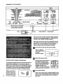
IMPORTANT PRECAUTIONS
2
The decal shown at the right has been
placed on your treadmill. If the decal Is
missing, or if it is not legible, please call
our toll-free HELPLINE to order a free replacement decal (see the back cover of
this manual). Apply the decal in the location shown.
J_ WARNI..NG!
• Never allow ch,ldren
to play on or around
• treadmill.
5torage latch must be
fully en.qaged before
treadmill is moved or
stored.
o
o II
© 1
o °11
3
BEFORE YOU BEGIN
Thank you for selecting the PROFORIVP CROSSWALK
PLUS treadmill. The CROSSWAIJ( PLUS treadmill
blends advanced technology with Innovative design to
let you enjoy an excellent form of cardiovascular exercise in the convenience and privacy of your home.
For your benefit, read this manual carefully before
using the treadmill. If you have additional questions,
please call our toll-free HELPL|NE .at1-800-736-6879,
Monday through Saturday, 7 a.m. until 7 p.m. Central
Time (excluding holidays). To help us assist you,
please note the product model number and eadal number before calling. The model number of the treadmill
is 831.297480. The sedal number can be found on a
decal attached to the treadmill (see the front cover of
this manual for the location).
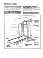
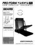
Before reading further, please review the drawing
below and familiarize yourself with the parts that are
labeled.
Book Rack
Accesso_Trey
Holder (Water
Bottle is not
Included)
Llpper Body
Arms
FRONT
BACK
Rear Roller
Adjustment Bolt
4
;ushloned Walking
Ptatform
RIGHT SIDE
ASSEMBLY
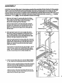
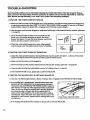
CAUTION: Read and follow step I below before removing the r_lnlng
fie (see drewlng 1). If the restral.nIng fie is removed prematurely, esdous bodily Injury may result. Assembly requires two people. Set the treadmill in a cleared ares and remove the packing materials except for the restraining tie. Do not dispose of the
pacldng materials until assembly is completed. Use the HARDWARE IDENTIFICATION CHART in the center of this
manual to identify the pads used in assembly. Assembly requires the Included allen wrench L,
a phillips
screwdriver
-=====_,
and two adjustable wrenches €1:_=_.
1. Slide the Left Upright (1) onto the left side of the Base
(59). It may be necessary to firmly push down on the
Left Upright until it is fully seated on the Base.
Remove the restraining tie from the Base.
Attach the left handrail to the Base (59) with a Handrail
Bolt (93), 3/8" Washer (67), and Handrail Nut (4). Do not
tighten the Handrail Bolt yeL Using the allen wrench,
tighten two Upright Screws (63) into the Left Upright (1)
and the Base.
59
Restraining
2. Slide the Right Upright (44) onto the right side of the
Base (59). It may be necessary to firmly push down
on the Right Upright until it is fully seated on the
Base. Be careful not to pinch the Wire Harness (25)
between the Right Upright and the Base.
Attach the right handrail to the Base (59) with a Handrail
Boll (93), 3/8" Washer (67), and Handrail Nut (4). Do not
tighten the Handrail Bolt yet. Using the allen wrench,
tighten two Upright Screws (63) into the Right Upright
(44) and the Base.
Hand tighten the Handrail Nuts (4) used in steps I and 2.
Using a wrench, tighten the Handrail Bolts (93) used in
steps 1 and 2. Remove the wire ties (not shown) attaching the Console Base (9) to the Right Upright (44).
3. Set the Console Base (9) on the Left and Right Updghts
(1, 44). Attach the Console Base with four Screws (75).
While one person carefully feed= any slack Wire Hamess
(25) down into the Right Upright (44), a second person
should carefully pull the slack Wire Harness from the
lower end of the Right Upright.
Align the holes !n the Book Rack (62) with those in the
Console BaseJ'9). Attach the Book Rack to the Console
Base with four Screws (75) as shown.
75
75
5
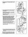
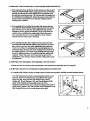
4. With the help of a second person, carefully lower the Left
and Right Uprights (1,44) until the handrails are resting
on the floor.
1
4
Attach six Base Pads (57) to the bottom of the Base (59)
in the indicated locations. Note: One extra Base Pad
may be included.
See drawing 4 above. With the help of a second person,
raise the Left and Right Updghts (1,44) until the Base
(59) is resting fiat on the floor.
Before moving the treadmill, see HOW TO MOVE THE
TREADMILL on page 11.
6. Insed two Resistance Bracket Bolts (107) with Bracket
WasherS (70) into the Left Updght (.1). Slide two Star
Washers.(.€03), a_,p_.r..(106),
,andtwo more Star
•Washers (103) onto the Bolts. Make sure that the
Spacer is turned so the widest slde is facing the Left
UpdghL Tighten the Bolts into the Resistance Bracket
(104) at the lower end of the left Upper Body Arm (96).
(Note: It may be necessary to loosen the Resistance
Knob [97] and pivot the Resistance BmckeL)
6
Attach the right Upper Body Arm (96) as desqdbed
above. Make sure that both Upper Body Arms are on the
correct side of the Console Base (9) as shown.
See drawing 2 on page 5. Feed the slack Wire Hameas
(25) into the Base (59).
7. Remove the backing from the Adhesive Clip (7"/). Press
the Adhesive Clip onto the Rear Roller Endcap (78) in the
indicated location. Press the Allen Wrench (76) into the
Adhesive Clip.
Make sure that all parts are tightened before you use the
treadmill. Note: To protect the floor or carpet, place a
mat under the treadmill. For Information
On ordering a
mat, see REPLACEMENT PARTS on the back cover.
"
76
OPERATION AND ADJUSTMENT
THE PERFORMANT
LUBE TM WALKING BELT
Your treadmill features a walking belt coated with
PERFORMANT LUBE TM, a high-performance lubricant.
IMPORTANT: Never apply silicone spray or other
substances to the walking belt or the walking platform. They will deteriorate the walking belt and
cause excessive wear.
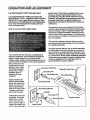
HOWTO
electric shock. This product is equipped with a cord
haying an equipment-grounding conductor and a
grounding plug. Plug the power cord into a surge
protector, and plug th.e surge protector into an eppropdate outlet that is properly Installed and
grounded In accordance with all local codes and
ordinances.
This product is for use on a nominal 120-volt circuit,
and has a grounding plug that looks like the plug Hlustrated in drawing 1 below. A temporary adapter that
looks h'kethe adapter illustrated in drawing 2 may be
used to connect the surge protector to a 2-pore receptacle as shown in drawing 2 if a propedy grounded outlet is not available.
PLUG IN THE POWER CORD
The temporary adapter should be used only until a
properly grounded outlet (drawing 1) can be installed
by a qualified electrician.
The green-colored dgid ear, lug, or the like extending
from the adapter must be connected to a permanent
ground such as a propedy grounded outlet box cover.
Whenever the adapter is used it must be held in place
Your treadmill, like any other type of sophisticated
by a metal screw. Some 2-pole receptacle outlet box
electronic equipment, can be seriously damaged by
covers ere not grounded. Contact a qualified elecsudden voltage changes in your home's power.
. _ , trician to determine if the outlet box cover is
Voltage surges, spikes, and noise Intederance can re.
grounded before using an adapter.
suit from weather conditions or from other appliances
being turned on or off.
To decrease the possibility of your tread1
/Grounded
Outlet Box
mill being damaged,
always use a surge
protector (not inGrounding Pin
cluded) with your
Grounding
treadmill.
Groundi.g
plug
+
Surge protectors are
sold at most hardware
stores and depadment
stores. Use only a ULlisted surge protector,
rated at 15 amps, with a
14-gauge cord of five
feet or less in length.
This product must be
grounded. If it should
malfunction or break
Grounded Outlet Box
Adapter
_.
.Grounding Pin i
Protector
(_
,
Grounding Plug
down, grounding provides a path of le_t resistance for electdc current to reduce the Ask of
Metal Screw
7
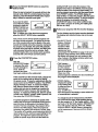
DIAGRAM OF THE CONSOLE
Displays
_..-..=
INSERT KEY
RESE'r SPEED
SE'I" SPEED
Note: If there is a thin sheet
of clear plastic on the face
of the console, remove it.
• Clip "
ON
OFF
"_ a_ _,
_"
L._9 J_J
17
Incline Buttons
__{Key
Pulse Sensor •
If the key is in the console, remove it. Make sure that
the power cord is properly plugged in. (See HOW TO
PLUG IN THE POWER CORDon page-7:)_
Next, step onto the foot rails of the treadmill. Find the
.clip attached to the key (see the drawing abo_,e), and
slide the dip onto the waistband of your clothing.
Follow the steps below to operate the console:
B
Insert the key fully into the power switch.
The four displays •
and the green manual mode
indicator will light..
B
STEP-BY-STEP
CONSOLE OPERATION
The treadmill console features a manual mode and four
preset workout programs. In the manual mode, the .
speed of the walking belt can be changed with the electronic speed control. When one of the preset programs
is selected, the console .will automatically control the
speed as it guides you through an effective workout.
8
Before operating the
console, make sure
thatthe on/off switch
near the power cord
is in the =on" position.
• B
Position
=On"
Reset the speed control.
Slide the speed control down to
the "RESET=position. Note:
Each time the walldng belt Is
stopped, the speed control
must be moved to the
"RESET" position before the
walking belt can be. restarted.
Set a speedsetttng.
Refer to the drawing above. Slide the speed control
upward to set a speed setting. Note: If the key was
just Inserted, the walking belt will not begin to
move yet.
B
Pressthe SELECTMODEbuttonto selectthe
desiredmode.
walking belt will move dudng the program. If the
program is tco easy or too difficult' move the apeed
control to s_ect a new maximum speed setting; To
stop the program temporarily, slide the speed co_ml
to the "RESET" position.The SPEED diaplay will _,
begin to flash. To restart the program, slide the speed
controlup to the dsstrad position.To end the program
before the program is completed, press the
START/STOP button. If you select a different program whl!e a program is running, the walking belt
will slow to a stop.
Whenthekeyis Inserted,the
console will be in the
manual mode. Note: If a preset program has been
selected, press the SELECT MODE button repeatedly to select the manual mode again.
If you want to select
one of the four preset
programs, press the
SELECT MODE button. The top red program indicator will
light. To select one of the other three programs,
press the SELECT MODE button repeatedly.
Note: There are two twenty-minute programs and
two thirty-minute programs. The graphs in the canter of the console show how the speed of the walkIng belt will change dudng the programs. Dudng the
top program, for example, the speed will gradually
Increase dudng the first ten minutes, and then gradually decrease during the last ten minutes. Each
program begins with a two-minute warm-up period,
and ends with a two-minute cool-down period.
I_
Press the START/STOP button.
START/STOP button
is pressed, the walk- ing belt will begin to
move. Hold the
handrails and care-
5
sr,_3-/stop
fully begin walking on the walking belt.
If the console is in the manual mode, change the
speed of the walking belt as desired by sliding
the speed control. To stop the walking belt, slide the
speed control to the "RESET" position. The SPEED
display will begin to flash. "to restart the walking :
belt, slide the speed control upward. Note: The
• walking belt can also be stopped by pressing the
START/STOP button; however, this will reset the
displays. To restart the walking belt, slide the speed
control to the =RESET" position, slide It upward, and
then press the START/STOP button.
If a preset program is selected;, the speed of the
walking bell will change automatically dudng the program as shown by the graphs in the center of the
console. The timeremaining in the program will be
shown in the TIME display. When the program is
completed, thewalking belt will slow to a stop. Note:
The position of the speed control determines both the
speed range and the maximum speed setting for the
program. The higher the speed control is sot, the
greater the speed range will be and the faster the
r_
Follow your progress with the monitor displays.
The four displays provide instant exercise feedback,
The displays are explained below and on the next
page,
• CALS./FAT CALS.
display--Displays
I F_IFI
the approximate
I-IL.tL-t I
numbers of both
CALS./FATCALS.
calories and fat
calories you have
burned (see FAT BURNING on page 14 for an explanation of fat calodes). Every seven seconds,
the display will change from one number to the
other. Arrows in the display will show which numbar is currently displayed.
When the console
LSin the manual
mode, the elapsed
time will be shown.
When one of the
.
/_38
TIME
preset programs is selected, the time remaining in
the program will be displayed.
Displays the speed
=_
of the walking belt,
in miles per hour or
-SPEED
kilometers per
,
hour. An MPH or a
KPH will appear in the display to show.which unit
of measurement is selected.
SPEEOdspay--I
I
To change the unit of measurement, hold down
the START/STOP button while inserting the key
into the console. An "_' (for English system*miles
per hour) or"M _ (for Metric system--kilometers per
hour) will appear in the CAL/FAT CAL display.
Press the SELECT MODE button to change the unit of measurement. Remove and then reinsert
the key.
• DISTANCE/
PULSEdisplay
Displaysthe
distanceyouhave
walkedor run.If
the MPH indicator
appears in the SPEED display, the distance will
be displayed In miles. If the KPH Indicator appears, the distance will be displayed In kilometers. Note: The DISTANCE/PULSE display also
shows your pulse when the pulse sensor is used.
When you are finished,
Step onto the foot
rails and remove
the key from the
console. Store the
key In a secure
place. In addition,.
move the on/off switch to the "o_ position..(See the
drawing near the bottom of page 8.)
THE INFORMATION
B
MODE
Measure your pulse, If'desired.
The console features an Information mode that keeps
To usethe pulse sensor, stand on the foot rails _nd " track of the total time and distance accumulated on the
treadmill To access this mode, hold down the START/
place your thumb on the pulse sensor as shown.
STOP button while inserting the key into the console.
The TIME display will show the total time. The DISThe pulse sensor
TANCE/PULSE display will show the total distance (if
is pressure-a_Pulse
the total distance exceeds 999, the thousands and ten
vated. Fully press
down the pulse
sensor. Do not
press too hard,
or the circulation
in your thumb
will be restricted,
and your pulse
will not be detected. Next, slightly raise your
thumb until the hesrt-shaped Indicator In the DISTANCE/PULSE display flashes steadily. Hold your
thumb at this level. After 5 to 10 seconds, your
pulse will be displayed.Hold your thumb on the
sensor for another 15 secondsfor the most accurate reading. If the displayed pulse appears to be
too high or too low, or if your pulse is not displayed,
lift your thumb off the sensor and allow the display
to reset. Press down again on the sensor as described above. Make sure that your thumb is pusi_
tioned as shown, and that you are applying the
proper amount of pressure to the pulse sensor.
Try the sensor several times until you become familIar with it. Remember to stand _'11while measuring
your pulse.
B
Change the Incline of the treadmill, If desired.
To change the incline, hold down
one of the incline
buttons until the desired incline is
reached.
10
remove the key.
thousands digits will be shown in the SPEED display).
The CAL/FAT CAt.: display will show an "E" or an =M,"
indicating miles or kilometers (see SPEED DISPLAY
on page 10). To exit the information mode, remove the
key from the console.
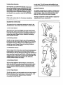
HOW TO USE THE UPPER BODY ARMS
As you exercise on
Body
the treadmill, you .. -.l:-Upper
can hold either the
handrailsor the
upper body arms.
The upper body
arms are designed
to exercise your
arms, shoulders,
and back for a total
body workout. Hold
one upper body
arm .with each
hand, and move
them forward and
back as you walk
on the treadmill.
To vary the intensity of your upper body exercise, the
resistance of the upper body arms can be adjusted. To
increase the resistance, turn the resistance knobs
clockwise; to decrease the resistance, turn the knobs
•counterclockwise.
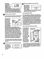
HOW TO FOLD AND MOVE THE TREADMILL
HOW TO FOLD THE TREADMILL FOR STORAGE
Before folding the treadmill, unplug the power cord. Caution:
You must be able to safely lift 45 pounds (20 kg) in order
to raise, lower, or move the treadmill.
1. Hold the treadmill with your hands In the locations shown
at the dghL To decrease the possibility of Injury, bend
your legs and keep your back streight- As you raise
the treadmill, make sure to rift with your legs rather
than your back. Raise the treadmill about halfway to the
vertical pos'_ion.
.
Move your dght hand to the position shown and hold the
treadmill firmly. Raise the treadmill until the storage latch
closes over the frame guide. Make sure that the storage
latch closes fully over the frame guide.
To protect the floor or carpet from damage, place a
mat under the treadmill Keep the treadmill out of direct sunlight. Do not leave the treadmill In the storage
position in temperatures above 85 ° Fahrenheit.
Closed
HOW TO MOVE THE TREADMILL
Before moving the treadmill, convert the treadmill to the storage position as described above. Make sure that the storage latch is closed fully over the frame guide.
1. Hold the handmJlSand place one foot on the base as shown.
2. Tilt the treadmill back until it mils freely on the front wheels.
Carefully move the treadmill to the desired location. Never
move the treadmill without tipping it back, or the base
pads may come off. To reduce the risk of Injury, use
extreme caution while moving the treadmill. Do not attempt to move the treadmill over an uneven surface.
3. Place one foot on the base, and carefully lower the treadmill until it is resting in the storage position.
HOW TO LOWER THE TREADMILL FOR USE
1" Hold the upper end of the treadmill with your dght hand as
shown. Using your left thumb, slide open the storage latch
and hold it open. Pivot the treadmill until the frame and
foot rail are past the storage latch.
2. Hold the treadmill firmly with both hands, and lower the
treadmill to the floor. To decrease the possibility of injury, bend your legs and keep your back straight.
Front Wheels
TROUBLE-SHOOTING
Most treadmill problems can be solved by following the simple steps below. Rnd the symptom that applies, and follow the steps listed. If further assistance Is needed, call our toil-fros HELPUNE at 1-800-736.
6879, Monday through Saturday, 7 am. until 7 p.m. Central Time (excluding holidays).
...
1. sYMPTOM: THE POWER DOES NOT TURN ON
a. Make sure that the power cord Is pl[Jgged into a surge protector, and that the surge protector is plugged into
a properly grounded outlet. (See HOW TO PLUG IN THE POWER CORD on page 7.) Use only a UL.-listed
surge protector, ra|ed at 15 stops, with a 14-gange cord of five feet or less in length.
b. After the power cord has been plugged in, make sure that the keyis fully Inserted into the console. (See step
1 on page 8.)
c. Check the cimuit breaker located on the treadmill near the
power cord. If the switch protrudes as shown, the circuit
breaker has tripped. To reset the circuit breaker, walt for five
minutes and then press the switch back in.
Tripped
d. Check the on/off switch located at the front of the treadmill
near the power cord. The switch must be In the =on"position.
Position
"On"
2. SYMPTOM: THE POWER TURNS OFF DURING USE
a. Check the circ=jitbreaker located on the treadmill frame near the power cord (see 1. c. above). If the circuit
bre;ake_has tripp_l,_Nait for five minutes and then press the switch back in.
b. Make sure that the power cord is plugged in.
c. Remove the key from the console. Reinsert the key fully into the console. (See step I on page 8.)
d. Check to make sure that the on/off switch is in the "on" position. (See 1. d. above.)
e. If the treadmill still will not ran, please call our toll-free HELPLINE.
3. SYMPTOM: THE WALKING BELT SLOWS WHEN WALKED ON
a. Use only a UL-listed surge protector, rated at 15 amps, with a 14-gauge cord'of five feet or less in length.
b. !f the walking belt is overtightened, treadmill performance may
decrease and the walking belt may be permanently damaged.
Remove the key and UNPLUG THE POWER CORD. Using the
allen wrench, tum both rear miler adjustment belts counterclockwise, 114of a tum. When the walking belt is properly tightened,
you should be able to lift each side of the walking belt 2-3
inches off the walking platform. Be careful to keep the walking
belt centered. Plug in the power cord, insert the key and run the .
treadmill for a few minutes. Repeat until the walking belt is propedy tightened.
Rear Roller Adjustment Bolts
c. If the walking belt still slows when walked on, please call our toll-free HELPLINE.
12
4. SYMPTOM: THE WALKING BELT IS OFF-CENTER WHEN WALKED ON
a. If the walking bell has shifted to the left, first remove the key and
UNPLUG THE POWER CORD. Using the 3/16" end of the allen
wrench, tum the left rear roller adjustment bolt clockwise, and
the dght bolt counterclockwise, 1/4 of a turn each. Be careful not
to overtighten the walking belt. Plug in the power cord, insert the
key and run the treadmill for a few minutes. Repeat until the
walking belt is centered.
b. ff the walking belt has shifted to the right, first remove the key
and UNPLUG THE POWER CORD. Using the 3/16" end of the
alien wrench, tum the left rear roller adjustment bolt counterclockwise, and the dght bolt clockwise, 1/4 of a turn each. Be
careful not to overtighten the walking bell Plug in the power
cord, insert the key and run the treadmill for a few minutes.
Repeat until the walking belt is centered.
a
b
c. If the walking belt slips when walked on, first remove the key
and UNPLUG THE POWER CORD. Using the 3/16" end of the
allen wrench, turn both rear roller adjustment bolls clockwise,
1/4 of a turn. When the walking boll is correctly tightened, you
should be able to lift each side of the walldng belt 2-3 inches off
the walking platform. The center of the walking bolt should just
touch the walking platform. Be careful to keep the walking bell
centered. Plug in the power cord, Insert the key and run the
•treadmillfor a few minutes. Repeat until the walking belt is propedy tightened.
5. SYMPTOM: THE TREADMILL SITS UNEVENLY ON THE FLOOR
a. Make sure that the six base pads are attached to the treadmill (see assembly step 5 on page 6).
6. SYMPTOM: ONE OF THE UPPER BODY ARMS SQUEAKS DURING USE
a. Correcting this problem requires a small amount of white madne grease, available at most hardware stores.
Turn the Resistance Knob (97) counterclockwise until ltcan be
removed. Remove the I_esistance Cone (98) and the Upper
Body Arm (96), along with the 3/8" Washers (67), Spdng
Washer (5), Thrust Washers (101 ), and Thrust Beadng (102).
(Note: If the Resistance Sleeve [99] comas out of the
Resistance Bracket [lo4], press It back In.) Apply a thin layer of
white rnadne grease to the outer surface of the Resistance Cone
(98). Reattach all parts in the order shown at the dghL
104
101
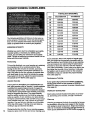
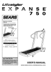
CONDITIONING
GUIDELINES
Training Zone (Beats/MIr_)
Age
Unconditioned
Conditioned
20
138-167
133-162
25
136-166
132-160
30
135-164
130-158
35
134-162
129-156
40
132-161
1.27-155
45
131-159
126-153
50
129-156
124-150
The following guidelines will help you to plan your exercise program. Remember--these are general guidelines. FOr more detailed information about exercise,
obtain a reputable book or consult your physician.
55
127-155
122-149
6O
126-153
121-147
65
125-151
119-145
EXERCISE INTENSITY
70
123-150
118-144
75
122-147
117-142
80
120-146
115-140
85
116-144
114-139
Whether you want to bum fat, strengthen your can:l]ovascular system, or increase your athletic performance, you can tailor your exercise to your specific
goals. The key to achieving the desired results Is to exercise with the proper intens_y.
Fat Burning
To bum fat effectivaly, you must exerdse at a relatively
low intensity level for a sustained period of time.
Dudng the first few minutes of exercise, your body
uses easily accessible carbohydrate calories for energy. Only after the first few minutes of exercise does
your body begin to use stored fat calories for energy.
If your goal is to bum fat, adjust the speed control on
the console to FAT BURN. (See page 8.)
Aerobic Exercise
If your goal is to strengthen your cardiovascular system, your exercise must be =aerobic." Aerobic exercise
is activity that requires large amounts of oxygen for
prolonged pedods of time. This increases the demand
on the heart to pump blood to the muscles, and on the
lungs to oxygenate the blood. The proper intensity
level for aerobic exercise can be foudd by using your
pulse as a guide:As you exercise, your pulse should
be kept at a level between 70% and 85% of your maximum possible heart rate. This is known as your training zone. You can find your training zone in the table
at the top of this page. Training zones are listed according to age and physical _ondRion.
14
Dudng the first few months of your exercise program,
keep your pulse near the low end of your training zone
as you exercise. After a few months of regular exercise, your pulse can be gradually increased until it is
near the middle of your training zone as you exercise.
You can measure your pulse using the pulse sensor.
Exercise for about four minutes, and then measure
your pulse immediately. If your pulse is too high or too
low, adjust the intensity of your exercise. It may also
be helpful to set the speed control on the console to
AEROBIC to help you maintain the proper intensity
level. (See page 8.)
_Performance Training.
if your goal is high performance athletic conditioning,
set the speed control on the console to PERFORMANCE to help you maintain the proper intensity level.
(See page 8.)
WORKOUT GUIDELINES
Each workout should include three pads: (1) a warmup, (2) training zone exercise, and (3) a cool-down.
Warm-up
Warming up prepares the body for exercise by increasing drculation, dalivedng more oxygen to the muscles
and raising the body temperature. Begin each workout
with 5 to 10 minutes of stretching and light exercise to
warm up (see SUGGESTED STRETCHES on page 15).
TrainingZoneExercise
to cool down. This will increase the flexibility of your
muscles and _11 help to prevent post-exercise problems.
Afterwarmingup, Increase
theintensityofyourexercise until your pulse is in your training zone for 20 to
60 minutes. (Dudng the first few weeks of your exercise program, do not keep your pulse in your training
zone for longer than 20 minutes.) Breathe regularly
and deeply as you exerolse--never hold your breath.
Exercise Frequency
To maintain or improve your condition, complete thr_workouts each week, with at least one day of rest between workouts. After afew months, you may complete up to five workouts each week if desired.
Cool-down
Finish each workout with 5 to 10 minutes of stretching
SUGGESTED
The key to success is to make exerdse a regular and
enjoyable part of your everyday life.
STRETCHES
The correct form for several basic stretches is shown in the
drawings below. Move slowly as you stretch--never bounce.
1. Toe Touch Stretch
Stand with your knees bentslightly and slowly bend forward
from your hips. Allow your back and shoulders to relax as you
reach down toward your toes as far as possible. Hold for 15
counts, then relax. Repeat 3 tirne_. Stretches: Hamstrings,
back of knees and back.
2. Hamstring Stretch
Sit with one leg extended. Bring the sole of the opposite foot
toward you and rest it against the inner thigh of your extended
leg. Reach toward your teas as far as possible. Hold for 15
counts, then relax. Repeat 3 times for each leg. Stretches:
Hamstdngs, lower back and groin.
3. Calf/Aehillas
Stretch
With one leg In front of the other, reach forward and place your
hands against a wall. Keep your back leg straight and your
back foot flat on the floor. Bend your front leg, lean forward and
move your hips toward the _all. Hold for 15 counts, then relax.
Repeat 3 times for each leg. To cause further stretching of the
achilles tendons, bend your back leg as well. Stretches:
Calves, achilles tendons and ankles.
4, Quaddoeps
Stretch
With one hand against a wall for balance, reach back and
grasp one foot with your other hand. Bdng your heel as close
to your buttocks as possible. Hold f_r 15 counts, then relax.
Repeat 3 times for each leg. Stretches: Quaddceps and hip
muscles.
5. Inner Thigh Stretch
Sit with the soles of your feet together and your knees outward.
Pull your feet toward your groin area as far as possible. Hold
for 15 counts, then relax. Repeat 3 times. Stretches:
Quaddceps and hip muscles.
3
Remove this HARDWARE IDENTIFICATION CHART, EXPLODED DRAWING, and PART LIST from the manual.
Save this page for future reference.
HARDWARE IDENTIFICATION CHART
The chart below is provided to help you identify the small parts used in assembly. The number in parenthesis
below each part refers to the key number of the part. The second number refers to the quantity used In assembly,
D@
3/8" Washer (67)-6
U©
Bracket Washer (70)-4
Screw (75)-8
Star Washer (103)-8
Upright Screw (63)-4
Handrail Nut (4)-2
_\\\\\1
Resistance Bracket Bolt (107)-4
D®
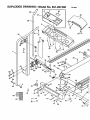
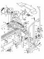
EXPLODED DRAWING--Model No. 831.297480
Rl19_
92
6
•
51
63
70
107
106
102
5
97
81
*'%
93
.o J°
67
71
73
66
72
6
19
113
64
15
116
34*
110
100
26
28
19
i
28
97
84
\
98
99
13
17
109
5
48
67
67
103
f
105
24
i
70
23
57
94
52 66
88
6
°°
41 22
!
"
i
56
6
104
PART LIST--Model No. 831.297480
Key No. Part No.
1
2
3
4
5
6
7
8
9
10"
11
12
13
14
15
16
17
18
19
20
21
22
23
24
25
26
27
28
29
30
31
32
33
34"
35
36
_
39
40
41
42
43
44
45
46
47
48
49
50
51
52
53
54
55
56
57
53
59
60
61
62
63
133O14
131882
135539
105477
128005
119425
131161
128113
131606
135192
119038
126134
124669
122812
014117
115523
120867
135194
120630
107503
130993
013307
NSP
013300
135195
134690
133333
125802
013322
109382
124695
102634
135197
133966
126747
133413
125198
119163
100498
016029
013601
112609
014127
133017
133685
130868
129168
131639
127098
131738
129734
130251
135199
129004
013430
129642
129740
013547
135726
130822
117806
131607
013484
Qty.
1
1
1
2
2
8
1
1
1
1
1
1
1
1
1
1
1
1
23
1
1
2
1
4
1
1
8
4
4
1
1
1
2
1
1
1
1
1
1
2
3
1
3
1
2
2
28
1
2
1
2
4
1
1
2
2
7
1
1
1
2
1
4
Description
Left Updght
Front Frame Cover
Incline Motor Guard
Handrail Nut
Spring Washer
3/8" Lock Nut
Speed Knob
Speed Potantiometer
Console Base
Console
Key/Clip
Motor Belt
Power Cord
Motor Tension Washer
Motor Tension Star Washer
InclineW_OT_
Motor Tension Nut
Motor Hood
Small Screw
Motor Pivot Bolt
• Choke
Incline Belt
Frame
Anchor Screw
Wire Harness
Motor-ControUerWire
Cover Clip
HoodAnchor
Frame Cover Screw
Circuit Breaker
Grommet
Ground Wire
Foot Rail
Motor/PuUey/Rywheel/Fan
Pulley/Flywheel/Fan
Motor
Controller
On/Off Switch
Magnet
4" Cable Tie
InclineTube/Incline Motor Bolt
Front Roller Adj. Bolt
AdjustmentWasher
Right Upright
Upright Spacer
Base Wheel Bolt
Belly Pan Screw
Belly Pan
Belt Guide
Storage Latch
Storage Latch Spdng
Frame Guide
Rear Frame Cover
Wire Harness Grommet
Upright Pivot Belt
Base Wheel
Base Pad
Motor Tension Bolt
Base
Safety Cover Connector
Incline Leg Wheel Bolt
Book Rack
Upright Screw
Rll A
Key No. Part No.
64
65
66
67
68
69
70
71
72
73
74
75
76
77
78
79
80
81
82
83
84
65
86
87
88
89
90
91 .
92-93
94
95
96
97
98
99
100
101
102
103,
104
105 :
106
107
108
109
110
_11"P
112
113
114
115
-11_
#
#
#
#
#
#
128903
116927
013576
014132
121576
126819 014068
133013
052012
100606
013342
126996
128457
016028
131635
133845
012056
131605
129639
01 6857
135201
165200
101174
131751
134510
129814
133598
116926
131753
124614
132681
105500
131593
126843
126828
126827
134650
102973
106896
014149
126773
126644
132583
132637
126960
125203
102959
117882
102955
120668
012152
119070
122.125
112083
112083
102246
107771
130426
133025
Qty.
1
1
8
10
2
4
6
1
2
2
2
18
1
1
1
1
4
1
1
4
1
1
8
8
1
1
1
1
1
2
1
•2
2
2
2
2
1
4
2
8
2
2
2
4
1
1
1
1
1
1
1
1
1
1
1
1
1
1
1
DeecrlpUon
Lift Board
Wire Tie Holder
Latch-Frame Guide Screw
3/8" Washer
Roller Endcap NUt
Plastic Stand-Off
Endcap/Bracket Washer
Incline Leg
Incline Leg Wheel
Rear Roller Endcap Screw
Adjustment Belt
Screw
Alien Wrench
Adhesive Clip
Rear Roller Endcap
Rear Roller
Incline Leg Nut
Latch Decal
Battery Cover
8" Cable Tie
Walking Belt
Walking Platform
Platform Screw
isolator
Incline Tube
Shock
Front Roller/Pulley
Releasable Cable Tie
Storage Latch Bracket
Handrail Bolt
Frame Guide Spacer
Foam Grip
Upper Body Arms w/Foam
Resistance Knob
Resistance Cone
Resistance Sleeve
Electronics Bracket
Thrust Washer
Thrust Beadng
Star Washer
Resistance Bracket
Resistance Belt
Res'_tance Bracket Spacer
Resistance Bracket Boll
Base Plug
Right Foot Rail
Small Bolt
Reed Switch Wire
Optic Switch
Optic Switch Bracket
Small NUt
Optic Disk
Optic Switch Nut
8" Blue Wire, 2 Female
4" Blue Wire, 2 Female
8" White Wire, 2 Female
8" White Wire, Male/Female
6" Green Wire
User's Manual
* Includes all pads shown in the box
# These pads are not illustrated
8EAR8
The model number and sedal number of your PROFORIvP CROSSWALK PLUS treadmill are listed on a decal attached to the frame.
•See the front cover of this manual to find the location of the decal.
Model No. 831.297480
QUESTIONS?
All replacement parts me available for immediate purchase or
special order when you visit your nearest SEARS Service Center.
To req!Jest service or to order parts by telephone, cell the toll-free
numbers listed at the left.
If you find that:
• you need help assembling or
operating the PROFORM •
CROSSWALK PLUS treadmill
• a part is missing
• or you need to schedule repair
service
When'requesting help or service, or ordering parts, please be prepared to provide the following information:
• The NAME OF THE PRODUCT (PROFORbP CROSSWALK
PLUS treadmill)
• The MODEL NUMBER OF THE PRODUCT (831.297480)
call our toll-free HELPLINE
1-800-736-6879
• The PART NUMBER OF THE PART (s_ethe EXPLODED
Monday-Saturday, 7 am-7 pm
Central Time (excluding holidays)
DRAWING and PART UST included in this manual)
• The DESCRIPTI_3N OF THE PART (see the EXPLODED DRAWING and PART UST included in this manual).
REPLACEMENT
PARTS
If parts become worn and need
to be replaced, call the following
t011-free number
1-800-FON-PART
(1-800-366-7278)
FULL 90 DAY WARRANTY
For 90 days from the date of purchase, if failure occurs due to defect in matadal or workmanship in this
SEARS TREADMILL EXERCISER, contact the nearest SEARS Service Center throughout the United
States and SEARS will repair or replace the TRF_h,DMILL EXERCISER, free of charge.
This warranty does not apply wh.enthe TREADMILL EXERCISER is used commercially or for rental purposes.
This warranty gives you specific legal dghts, and you may also have other dghts which vary from state
to state.
SEARS, ROEBUCK AND CO., DEPT. 817WA, HOFFMAN ESTATES, IL 60179
Part No. 133025 F04005-C
R1196A
Pdnted in USA © 1996 Seam, Roebuck and Co.