1
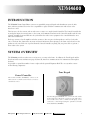
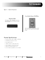
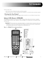
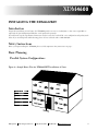
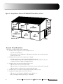
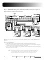
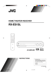
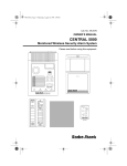
Xtreme Digital Music System XDM4600
4-Zone/6-Source
Owner’s Manual
XDM4600
SAFETY FIRST
READ ALL INSTRUCTIONS CAREFULLY BEFORE
INSTALLING OR USING THE XDM4600 SYSTEM
THE XDM4600 MUST BE INSTALLED BY M&S SYSTEMS DEALERS OR INSTALLERS, AND
MUST CONFORM TO ALL LOCAL BUILDING AND ELECTRICAL CODES.
Warning: Always follow these safety instructions.
Retain these instructions for future system reference.
• Read ALL safety and operating instructions before installing the XDM4600KIT.
• Adhere to all warnings on the XDM4600KIT and in these instructions. Follow all operating and installation instructions.
• CAUTION: These installation and servicing instructions are for use by qualified personnel only. To reduce the risk of electric
shock, do not perform any servicing other than that contained in the operating instructions unless you are qualified to do so.
• DO NOT attempt to service the XDM4600 yourself, as opening or removing covers may expose you to dangerous voltage or other
hazards. Refer all servicing to qualified service personnel.
The lightning flash with arrowhead symbol within an equilateral triangle is intended to alert the user to the presence of uninsulated
“dangerous voltage” within the product’s enclosure that may be of sufficient magnitude to constitute a risk of shock to persons.
The exclamation point within an equilateral triangle is intended to alert the user to the presence of important operating and maintenance
(servicing) instructions in the literature accompanying the product.
CAUTION
RISK OF ELECTRICAL SHOCK
DO NOT OPEN
CAUTION:
ADVERTISSEMENT:
TO PREVENT ELECTRICAL SHOCK
DO NOT REMOVE COVER. NO
USER-SERVICABLE PARTS INSIDE.
REFER TO QUALIFIED SERVICE
PERSONNEL.
HAUTE TENSION A L’INTERIEUR
DANGER POUR PERSONNES
NON QUALIFIEES.
• Locate the system away from heat sources such as radiators, heat
registers, stoves, or other heat producing products.
• DO NOT locate the system in the garage, the attic, or on any outside wall.
M&S Systems recommends an environmentally open placement of the
Central Controller for good airflow around the unit.
• Route power supply cords so they will not be walked on or pinched by items
placed near them.
• DO NOT expose the XDM4600 to moisture. Doing so can create fire or
shock hazards and impair the warranty.
• DO NOT place the Zone Keypad (XDM46K) unit in any wall cavity with
any other electrical wiring in the cavity. Avoid all other wiring.
• DO NOT overload wall outlets, extension cords, or integral convenience
receptacles as this can result in a risk of fire or electrical shock.
• DO NOT attach devices unauthorized for use with this system.
Authorized devices include:
- Audio components connected via a line level input.
- One pair of 8-ohm speakers per room station.
• Use only M&S Systems certified replacement parts and have them installed
by an M&S dealer or installer. Unauthorized substitutions can result in fire,
electric shock, or other hazards.
M&S Systems
!
2861 Congressman Lane
Dallas,Texas 75220
• Upon completion of any service or product repair, have the M&S Systems
dealer or installer conduct a safety check to ensure that the system is in proper
operating condition.
• Unplug the Central Controller (XDM46CC) from the wall outlet prior to
cleaning via a line level input/output. Use only a damp cloth to clean the
Central Controller and Zone Keypads. DO NOT use liquid cleaners or
aerosol cleaners.
• A polarized plug has two blades with one wider than the other. A grounding
type plug has two blades and a third grounding prong. The wide blade or the
third prong are provided for your safety. If the provided plug does not fit into
your outlet consult an electrician for replacement of the obsolete outlet.
DO NOT defeat the safety purpose of the polarized or grounding-type plug.
• For added protection for this product during a lightening storm, or when the
product is left unattended and unused for long periods of time, unplug it from
the wall outlet. This will prevent damage to the product due to lightening and
power-line surges.
• Press the power switch to the “ON” position to switch XDM46CC (or
XDM46EH) on. The Power Switch is a single-pole switch. This unit is not
disconnected from the AC power source as long as it is connected to the wall
outlet, even if this unit itself is turned off with the power switch. This state is
called the standby mode. In this state, this unit is designed to consume a very
small quantity of power.
REV. 12/13/04
800.877.6631
www.mssystems.com
i
TABLE OF CONTENTS
Safety First . . . . . . . . . . . . . . . . . . . . . . . . . . . . . . . . . . . . . . . . . . . . . . . . . . . . . . . . . .i
List of Figures . . . . . . . . . . . . . . . . . . . . . . . . . . . . . . . . . . . . . . . . . . . . . . . . . . . . . . .iii
Introduction . . . . . . . . . . . . . . . . . . . . . . . . . . . . . . . . . . . . . . . . . . . . . . . . . . . . . . . . .1
System Overview . . . . . . . . . . . . . . . . . . . . . . . . . . . . . . . . . . . . . . . . . . . . . . . . . . . . .1
System Specifications . . . . . . . . . . . . . . . . . . . . . . . . . . . . . . . . . . . . . . . . . . . . . . . . . . . . . . . . . . . . . . . . . . . . . . . . . . . .3
Using the XDM4600 . . . . . . . . . . . . . . . . . . . . . . . . . . . . . . . . . . . . . . . . . . . . . . . . . .4
Zone Keypad (XDM46K) . . . . . . . . . . . . . . . . . . . . . . . . . . . . . . . . . . . . . . . . . . . . . . . . . . . . . . . . . . . . . . . . . . . . . . . . .4
Infrared (IR) Remote (XDM46R) . . . . . . . . . . . . . . . . . . . . . . . . . . . . . . . . . . . . . . . . . . . . . . . . . . . . . . . . . . . . . . . . . .6
Door Station (DS3B2) . . . . . . . . . . . . . . . . . . . . . . . . . . . . . . . . . . . . . . . . . . . . . . . . . . . . . . . . . . . . . . . . . . . . . . . . . . .9
Installing the XDM4600KIT . . . . . . . . . . . . . . . . . . . . . . . . . . . . . . . . . . . . . . . . . . .10
Introduction . . . . . . . . . . . . . . . . . . . . . . . . . . . . . . . . . . . . . . . . . . . . . . . . . . . . . . . . . . . . . . . . . . . . . . . . . . . . . . . . . .10
Safety Instructions . . . . . . . . . . . . . . . . . . . . . . . . . . . . . . . . . . . . . . . . . . . . . . . . . . . . . . . . . . . . . . . . . . . . . . . . . . . . .10
Basic Planning . . . . . . . . . . . . . . . . . . . . . . . . . . . . . . . . . . . . . . . . . . . . . . . . . . . . . . . . . . . . . . . . . . . . . . . . . . . . . . . .10
Installing the Central Controller . . . . . . . . . . . . . . . . . . . . . . . . . . . . . . . . . . . . . . . . . . . . . . . . . . . . . . . . . . . . . . . . . .13
Installing the Audio Sources and IR Emitters . . . . . . . . . . . . . . . . . . . . . . . . . . . . . . . . . . . . . . . . . . . . . . . . . . . . . . . . .14
Installing the Zone Keypads . . . . . . . . . . . . . . . . . . . . . . . . . . . . . . . . . . . . . . . . . . . . . . . . . . . . . . . . . . . . . . . . . . . . . .16
Installing the Speakers . . . . . . . . . . . . . . . . . . . . . . . . . . . . . . . . . . . . . . . . . . . . . . . . . . . . . . . . . . . . . . . . . . . . . . . . . .18
Installing the Door Station . . . . . . . . . . . . . . . . . . . . . . . . . . . . . . . . . . . . . . . . . . . . . . . . . . . . . . . . . . . . . . . . . . . . . .19
Installing the Expansion Hub . . . . . . . . . . . . . . . . . . . . . . . . . . . . . . . . . . . . . . . . . . . . . . . . . . . . . . . . . . . . . . . . . . . . .19
Installing a Local Audio Source Wall Plate . . . . . . . . . . . . . . . . . . . . . . . . . . . . . . . . . . . . . . . . . . . . . . . . . . . . . . . . . .22
M&S Systems 2-Year Warranty . . . . . . . . . . . . . . . . . . . . . . . . . . . . . . . . . . . . . . . . .23
M&S Systems Registration Form . . . . . . . . . . . . . . . . . . . . . . . . . . . . . . .Inside Back Cover
ii
M&S Systems
2861 Congressman Lane
Dallas,Texas 75220
800.877.6631
www.mssystems.com
XDM4600
LIST OF FIGURES
Figure 1 —
Figure 2 —
Figure 3 —
Figure 4 —
Figure 5 —
Figure 6 —
Figure 7 —
Figure 8 —
Figure 9 —
Figure 10 —
Figure 11 —
Figure 12 —
Figure 13 —
Figure 14 —
M&S Systems
XDM4600KIT Components . . . . . . . . . . . . . . . . . . . . . . . . . . . . . . . . . . . . . . . . . . . . . . . . . . . . . . . . . . . . .2
Optional Components . . . . . . . . . . . . . . . . . . . . . . . . . . . . . . . . . . . . . . . . . . . . . . . . . . . . . . . . . . . . . . . . . .3
XDM46R Universal Learning Remote . . . . . . . . . . . . . . . . . . . . . . . . . . . . . . . . . . . . . . . . . . . . . . . . . . . . .6
Sample House Plan for XDM4600KIT Installation: 4 Zones . . . . . . . . . . . . . . . . . . . . . . . . . . . . . . . . . .10
Sample House Plan for XDM4600KIT Installation: 8 Zones . . . . . . . . . . . . . . . . . . . . . . . . . . . . . . . . . .11
Central Controller Wiring . . . . . . . . . . . . . . . . . . . . . . . . . . . . . . . . . . . . . . . . . . . . . . . . . . . . . . . . . . . . . .12
XDM4600KIT Wiring Scheme . . . . . . . . . . . . . . . . . . . . . . . . . . . . . . . . . . . . . . . . . . . . . . . . . . . . . . . . . .13
Wiring for Audio Sources and IR Emitters . . . . . . . . . . . . . . . . . . . . . . . . . . . . . . . . . . . . . . . . . . . . . . . .15
Zone Keypad Rough In . . . . . . . . . . . . . . . . . . . . . . . . . . . . . . . . . . . . . . . . . . . . . . . . . . . . . . . . . . . . . . . .16
Zone Keypad Wiring . . . . . . . . . . . . . . . . . . . . . . . . . . . . . . . . . . . . . . . . . . . . . . . . . . . . . . . . . . . . . . . . . .17
Door Station Wiring . . . . . . . . . . . . . . . . . . . . . . . . . . . . . . . . . . . . . . . . . . . . . . . . . . . . . . . . . . . . . . . . . .19
Back of the Expansion Hub . . . . . . . . . . . . . . . . . . . . . . . . . . . . . . . . . . . . . . . . . . . . . . . . . . . . . . . . . . . .20
4-Zone Expansion Hub Wiring . . . . . . . . . . . . . . . . . . . . . . . . . . . . . . . . . . . . . . . . . . . . . . . . . . . . . . . . . .21
Optional Local Audio Source Zone Wall Plate . . . . . . . . . . . . . . . . . . . . . . . . . . . . . . . . . . . . . . . . . . . . . .22
2861 Congressman Lane
Dallas,Texas 75220
800.877.6631
www.mssystems.com
iii
XDM4600
INTRODUCTION
The XDM4600 Xtreme Digital Music system is an expandable, integrated digital audio distribution system. It offers
music and intercom functions to four zones (expandable to eight) and allows communication with visitors at the
front door as well.
The four zones, the door station, and six audio sources connect to a single Central Controller. The Central Controller has
six analog line inputs for sourcing music to the system, and communication between the Central Controller and the zones
is digital. An infrared repeater built into the system allows the audio source equipment to be controlled from the zones
with a universal Remote.
Each zone contains a class-D amplifier and other circuitry to drive one pair of 8-ohm speakers as well as a local audio
source. The front door chime mutes any music and intercom function that is playing so the chime can be heard over the
speakers in each zone. Each zone is powered from the Central Controller, requiring only one power cable to go from a
house outlet to the system.
SYSTEM OVERVIEW
The XDM4600 provides six audio sources to four zones, or rooms, in the home. In addition, the Zone Keypads and the
Door Station have intercom functions (page all, listen all, front door communications) for communication throughout
the home.
It is possible to expand the number of zones to eight with the optional Expansion Hub. The core system kit consists
of the following components:
Zone Keypad
Central Controller
The Central Controller (XDM46CC) connects to six
audio sources in a central location and acts as a router to
control those sources
Four Zone Keypads (XDM46K) serve as intercoms and controls
for the audio sources. Each zone can select its own audio source.
A local audio source, such as a child’s own CD player, can be
connected to a Zone Keypad using the optional Local Audio
Source Wall Plate (XDMWP).
M&S Systems
2861 Congressman Lane
Dallas,Texas 75220
800.877.6631
www.mssystems.com
1
Figure 1 — XDM4600KIT Components
IR Remote
IR Emitters
The Universal Remote Control (XDM46R) is used to
control the audio sources. It is preprogrammed to control
the volume of the Zone Keypads, accepts programmed
macros and can control the audio equipment directly or
remotely through a Zone Keypad.
The IR Emitters (XDMIRE) connect the Central
Controller IR output to the audio equipment IR eye so the
IR Remote can be used to control that equipment from
the Zone Keypads. (Extra emitters can be purchased in
packages of six.)
Door Station
The Door Station (DS3B2) is installed at the front door and is used
as an intercom for communication with visitors. The system
accommodates one Door Station only. (The Door Station requires
rough-in kit ME3, which must be installed when pre-wiring is
done. The rough-in kit is shipped separately.)
2
M&S Systems
2861 Congressman Lane
Dallas,Texas 75220
800.877.6631
www.mssystems.com
XDM4600
Figure 2 — Optional Components
Local Audio Source Wall Plate
Expansion Hub
The Expansion Hub (XDM46EH) connects to
the Central Controller and expands the number
of zones to eight.
The Zone Wall Plate (XDMWP) allows a local
audio source to be connected to the local Zone
Keypad.
System Specifications
• Frequency Response: 20hz – 20KHz, +/- 0.5db max
• Total Harmonic Distortion: .2% max
• Power supply 110 volts
• 30 Watts a channel (8-ohm speakers only)
• Class D amplifiers reside with each keypad
• Fully functional keypad with IR receiver
• 4 stereo channels, expandable to 8 stereo channels
M&S Systems
2861 Congressman Lane
Dallas,Texas 75220
800.877.6631
www.mssystems.com
3
USING THE XDM4600
Zone Keypad (XDM46K)
From any Zone Keypad, you can talk and listen on the intercom, and you can control the music for the entire system
(party mode) or for the local zone only. With the universal Remote Control (XDM46R), you can control all audio
sources from a Zone Keypad.
Power
The POWER button on a Zone Keypad allows a user at a zone to turn the audio source on and off for the entire system,
or turn the audio source on and off at the local zone only. When the keypad power is on, the buttons are highlighted
with a soft blue backlight. When the power is off, the blue backlight is off.
Note:
When the power at a local zone is turned off, the intercom continues to function.
• To turn on the system music, press the POWER button on any Zone Keypad and hold it for at least 3 seconds. The
system automatically plays the audio sources that were previously selected at each keypad, and the music is heard
through all Zone Keypads.
• To turn off the system music, press the POWER button on any Zone Keypad and hold it for at least 3 seconds. The
music to all Zone Keypads is turned off.
• To turn on music for a local zone only, press and release, in less than 3 seconds, the POWER button on the Zone
Keypad. The system automatically returns to the source that was previously selected. The music is heard through the
local Zone Keypad only. To change the audio source, press one of the audio source buttons on the Zone Keypad.
• To turn off the music at a local zone only, press and release, in less than 3 seconds, the POWER button. All music is
turned off for the local zone. The intercom continues to function.
Volume
Music and intercom volume are independent of one another and are controlled separately.
Music Volume
The volume buttons on the Zone Keypad control the volume for that keypad only.
• To adjust the music volume, press VOLUME UP or VOLUME DOWN. The volume indicator lights show the
volume level.
• When the Zone Keypad is turned off and then turned back on, the music volume is reset to the default level.
• You can also adjust the music volume using the Remote Control volume buttons, which are preprogrammed
for this function.
Note:
If you go into learn mode and transfer volume functions from another remote,
this preprogrammed function is overridden and permanently lost.
Intercom Volume
When the LISTEN function is activated on the intercom, you can change the volume of the intercom.
• To adjust the intercom volume, press VOLUME UP or VOLUME DOWN.
• The set volume level is remembered and used the next time you enter Listen mode.
4
M&S Systems
2861 Congressman Lane
Dallas,Texas 75220
800.877.6631
www.mssystems.com
XDM4600
PRIVACY MODE ADDENDUM
Privacy Mode
From any zone keypad you can initiate privacy mode by pressing the volume up and down buttons
simultaneously. Once privacy is enabled the back light of the volume up and down buttons will be
more intense signifying that privacy mode is active.
To remove privacy mode from any zone keypad depress the volume up and down buttons simultaneously.
The back lighting of the volume up and down buttons will become intense signifying this mode has ended.
Operation Of Keypad While In Privacy Mode
• The volume buttons on the keypad still adjust music and intercom volume.
• All intercom functions will still be active. Follow operating instructions for these functions
-
Talk
-
Listen
-
Door Talk
• While the keypad is in privacy mode other zones will not be able to monitor or listen to that zone.
• When the zone keypad is turned off and then powered back on, the zone will remain in privacy
mode. When another zone initiates monitor the privacy initiated keypad even while in the off state
cannot be monitored.
Note: The only way to initiate and remove a keypad from privacy mode is to press both the volume
down button and volume up button simultaneously. Once the mode is activated the blue
back light will become more intense.
M&S Systems
2861 Congressman Lane
Dallas,Texas 75220
800.877.6631
www.mssystems.com
5
Listen
• To hear the sound and activity at all other zones, press the LISTEN button.
• The zone stays in Listen mode until you push any button, including LISTEN again, on the keypad.
• When you press LISTEN on a Zone Keypad, music to that zone is muted until you exit Listen mode.
Talk
• To talk to all other zones, press the TALK button.
• Release the TALK button when you are finished.
• When you press TALK, the music/audio to all zones is muted.
Door Talk
Allows users to talk and listen to visitors at the front door.
• Press TALK and LISTEN simultaneously to enter Door Talk mode. This allows you to talk to the Door Stations.
All other stations can hear the conversation.
• Release the TALK and LISTEN buttons to listen to the Door Station. The Listen mode is active for a total of
25 seconds after you release the TALK and LISTEN buttons. You may talk again at any time by pressing TALK
and LISTEN. Each time the buttons are released, you can listen for another 25 seconds, or until any zone
button is pressed.
• Door Talk mode is suspended at the end of the 25-second listening period, or if another button is pressed, except
for LISTEN or VOLUME, on any keypad.
Audio Source Buttons
The six audio source buttons and one LOCAL button on the Zone Keypad allow users to select an audio source for a
local zone or for all zones (Party Mode). When a source is selected, the blue backlight behind that button intensifies.
Note: You cannot control the details of the audio sources themselves using a Zone
Keypad. (i.e. you cannot change a CD track or a radio station.) However, if
you have a programmed XDM46R Universal Remote for specific functions,
like CD track changing, you can control the specific functions using the
universal remote control.
The audio source buttons are:
• TUNER
• SAT/CAB (Satellite and Cable)
• CD1
• CD2
• DVD
• MUSIC—Any auxiliary audio source that is connected to the Central Controller
• LOCAL—You can connect an audio source in each zone to the Zone Keypad.
This source is available to the local zone only and is not accessible by the entire system in Party Mode.
6
M&S Systems
2861 Congressman Lane
Dallas,Texas 75220
800.877.6631
www.mssystems.com
XDM4600
To select an audio source:
1. For a local zone, press and release the audio source button you prefer.
2. To play an audio source to all zones (Party Mode), press and hold, for 3 seconds, the audio source button you prefer.
Cleaning the Zone Keypad
Clean the zone keypad carefully using a cloth dampened with water only. Do not use any chemicals or spray cleansers.
Infrared (IR) Remote (XDM46R)
The XDM46R universal Remote Control, shown in Figure 3, manages all functionality of the audio source equipment.
It can be used directly with your audio equipment or, when the IR Emitters are installed, from a Zone Keypad in another
area of the house.
WARNING: THE VOLUME BUTTONS ARE PREPROGRAMMED TO CONTROL THE MUSIC VOLUME ON THE LOCAL
ZONE KEYPAD. IF YOU GO INTO LEARN MODE AND TRANSFER VOLUME FUNCTIONS FROM ANOTHER REMOTE,
THIS PREPROGRAMMED FUNCTION IS OVERRIDDEN AND PERMANENTLY LOST.
Figure 3—XDM46R Universal Learning Remote
A
B
C
D
E
F
G
H
I
J
K
OSD
INFRA-RED TRANSMITTER
INFRA-RED RECEIVER
DISPLAY (LCD) WINDOW
DEVICE BUTTONS
STORAGE BUTTONS
MACRO BUTTON
EDIT BUTTON
TIME/DATE BUTTON
LEARN BUTTON
CLEAR BUTTON
RESET BUTTON
- On Sceen Display
TIME - Display Current Time
REO.B - End Repeat
RTN
2861 Congressman Lane
Dallas,Texas 75220
- Record
REP. A - Start Repeat
- Audio/Video Mode
M&S Systems
REC
ZOOM - Zoom
- Return to Previous Page
800.877.6631
A/D
- Audio Channel
- Open Door
www.mssystems.com
7
Install Batteries
1. Remove the battery cover
2. Insert 4 AAA batteries. Follow the diagram to place them in the correct positions.
3. Close the battery cover until it clicks.
Set Time and Date
1. Press the EDIT button, then the TIME/DATE button. These buttons are located on the back of the remote.
Use a paperclip or similar tool to press these buttons. The display on the front of the remote shows SET HOUR.
2. Press VOLUME+ or VOLUME- to select the hour. The remote cycles through a 12 hour clock (AM and PM)
and then a 24 hour clock. A PM shows on the display for PM times. There is no display for AM.
3. Press CH+ and the VOLUME buttons to set the minutes, date, year, and day.
4. Wait a few moments and the remote returns automatically to its normal mode.
Learn Mode
The XDM46R is preprogrammed to control the volume at the Zone Keypads. You must transfer other signals from the
original audio equipment remotes by using Learn mode.
WARNING: THE VOLUME COMMANDS ARE PREPROGRAMMED. DO NOT LEARN THE VOLUME FUNCTIONS
FROM YOUR SOURCE REMOTES.
1. Press the LEARN button on the back of the Universal remote. Use a paperclip or similar tool to press this button.
The display shows LEARN blinking.
2. Press the device button of the audio source you want to transfer a signal for.
3. Press a storage button. This is the button that will be used to perform the signal you transfer. The word LEARN
stops blinking. The unit is now prepared to accept input from the original remote.
4. Place the original remote so that its infrared beam points at the bottom end of the XDM46R. The two remotes
should be 2-3 inches, or 5-8 centimeters, apart.
5. Press and hold the button on the original remote that contains the signal you want to transfer. When the information
has been transferred, the XDM46R display shows OK. Then the word LEARN starts blinking again.
6. Repeat steps 3-5 until all learning is complete.
7. When you are finished, wait 15 seconds and the XDM46R returns to its normal mode.
EXAMPLE
To transfer the signal that turns on the DVD player:
1. Press LEARN on the back of the XDM46R.
2. Press the DVD button on the front.
3. Press and hold the POWER button.
4. Point the original DVD remote at the XDM46R and press the POWER button on the original DVD remote.
Hold until the display shows OK.
To use the XDM46R to turn on the DVD player, press DVD, then POWER.
8
M&S Systems
2861 Congressman Lane
Dallas,Texas 75220
800.877.6631
www.mssystems.com
XDM4600
Note: If the display shows ERROR, repeat steps 3-5. Make sure you follow all steps
carefully.
Note: If the display shows NO DATA, there is no signal from the old remote.
Make sure the two remotes are close enough and lined up.
Edit Key Names
Each device key has a default name matching what is printed on the key, but you can change the name that appears
on the display. Each name can contain up to 8 characters.
1. Press the EDIT button on the back of the remote. Use a paperclip or similar tool to press this button. EDIT?
appears in the display.
2. Press the desired device or storage button whose display name you want to change. The current name for this
button appears in the display with the first character blinking.
3. Press VOL+ or VOL- to scroll through characters until you reach the character you want. You can press CLEAR
to clear the last character or insert a space. Names will be centered during operation.
4. Press CH+ to move forward to the next character or CH- to move back to the previous character.
5. When you are finished, press the EDIT button again or wait 15 seconds for the remote to go back to its
normal mode.
Note: Refer to the instructions that came with the XDM46R to see a list of the
available characters.
Program Macros
You can program macros into the XDM46R to perform a series of functions with just two key presses (MACRO +
assigned Storage or Device button). Each macro can be programmed to perform up to 20 steps.
To program a macro:
1. Press the LEARN button on the back of the remote. Use a paperclip or similar tool to press this button.
2. Press the MACRO button on the front panel of the remote. This puts you in Macro Learning mode.
The display shows MACRO?
3. Select a storage button (0-9) or a device button that will launch the macro.
4. Use the remote to walk through the steps you want the macro to perform.
- The default delay between steps when the macro is performed is 0.5 seconds. You can change this delay time
to anywhere from 1-99 seconds to allow for such things as device warm-up time. To change the delay time
between macro steps, press the button you want the delay to follow and hold it the amount of time you want to
delay. The display will count 1-99. Release the button when you reach the delay time you prefer.
Note:
An inserted delay does not count as one of the 20 possible macro steps.
5. Press the LEARN button on the back of the remote to finish the macro and return to normal mode.
M&S Systems
2861 Congressman Lane
Dallas,Texas 75220
800.877.6631
www.mssystems.com
9
EXAMPLE
OF PROGRAMMING A MACRO
To program a macro that turns on the tuner, turns on the CD player, opens the CD player drawer, waits 10 seconds
and closes the CD player drawer:
1. Press LEARN and MACRO.
2. Select CD1 as your macro storage key.
3. Press Tuner.
4. Press POWER.
5. Press CD.
6. Press POWER and hold for 5 seconds. This allows time for the CD player to turn on.
7. Press OPEN and hold for 10 seconds. This allows time for the drawer to open and for a CD to be inserted.
8. Press OPEN again. This closes the drawer.
9. Press LEARN. MACRO OK appears on the display.
To launch the macro, press MACRO and CD1.
Other Functions
Clear Stored Data
1. Press the CLEAR button on the back of the remote. Use a paperclip or similar tool to press the button.
2. Press the audio source button, storage key, or macro program you want to clear. If no button is pressed within
15 seconds, the remote exits Clearing Stored Data mode.
Reset the Remote
Press the RESET button on the back of the XDM46R. Use a paperclip or similar tool to press the button. After reset,
all data remains, but the clock and date have to be set again.
Low Battery Indicator
• When the batteries are low, a battery symbol appears on the display. The remote still operates.
• When the battery symbol starts blinking, all remote functions are locked until new batteries are installed.
Door Station (DS3B2)
• When someone presses the door chime, all music on the system is muted until the chime stops.
• The door chime can be heard in all zones, even if the Zone Keypad is turned off.
• Only one Door Station (DS3B2) can be used per system.
10
M&S Systems
2861 Congressman Lane
Dallas,Texas 75220
800.877.6631
www.mssystems.com
XDM4600
INSTALLING THE XDM4600KIT
Introduction
Designed for installation in new homes, the XDM4600 provides six sources of audio/music to four zones (expandable to
eight with the optional Expansion Hub that can be purchased separately).
If you follow the step-by-step illustrated instruction in this section, the result will be a successful professional-quality installation. If you need help with troubleshooting, please call our technical staff at 1-800-366-9422.
Safety Instructions
Before you begin installing the XDM4600, please read the important safety instructions on page i.
Basic Planning
Possible System Configurations
Figure 4—Sample House Plan for XDM4600KIT Installation: 4 Zones
M&S Systems
2861 Congressman Lane
Dallas,Texas 75220
800.877.6631
www.mssystems.com
11
Figure 5—Sample House Plans for XDM4600KIT Installation: 8 Zones
Layout Considerations
Plan where you will install the various components:
• Determine where the speakers in each zone will be located.
-
Consider sound distribution.
-
If the speakers are to be installed in a wall, make sure they don’t share a stud cavity with
speakers in other rooms.
• Determine the location in each room/zone for the keypad.
-
Consider convenient access, both manually and with the remote.
Avoid installing the keypad where direct sunlight will reach it. The infrared eye may not
recognize the remote’s command if sunlight interferes.
• Determine where the Central Controller will be located.
-
Make sure there is an electrical outlet nearby.
-
Make sure there are no heating elements or other heat sources located near the Controller.
-
Make sure there are no obstructions to wiring in the wall cavity.
• Determine where the zone line-level input/output wall plate will be located.
• Determine how wiring will be routed to each location.
12
-
Make sure you avoid wiring for 120/240V, security, dimmers, etc.
-
Plan so the length of wiring can be kept to a minimum.
M&S Systems
2861 Congressman Lane
Dallas,Texas 75220
800.877.6631
www.mssystems.com
XDM4600
System Wiring Considerations
• Use both CAT-5 and 16-gauge, 2-conductor wires for all runs from the Central Controller to the Zone Keypads.
• Use CAT-5 wires for the run from the Central Controller to the Door Station.
• Use 18-gauge, 2-conductor wire for all runs from the Zone Keypads to the speakers.
• When wiring the keypad, DO NOT confuse the 16-gauge, 2-conductor power wire that goes to the Central
Controller with the 18-gauge, 2-conductor wires that go to the speakers. Crossing these wires will result
in damage to the speakers and zone keypads.
• Keep all XDM4600 wiring away from 120/240V wires, security, dimmers, or other control wiring.
• Do not exceed 300 feet of CAT-5/16-gauge, 2-conductor wire run from the Central Controller to any Zone
Keypad.
• Label all wiring runs. The Zone Keypads and the Door Station both use CAT-5 wiring, but they use different
signals and voltages. Label the CAT-5 wiring, 18-gauge speaker wire and 16-gauge, 2-conductor power wire to
prevent Zone Keypad wires from being connected to the Door Station port, or the Zone power cable from being
plugged into the Zone speaker port.
• Do not staple wires. Stapled wires can cause shorts. Also, if a wire has been cut too short at one end, stapling
makes it impossible to pull additional wire through the wall.
• Do not splice wires. Splices are unreliable and defeat the signal isolation properties of the wires.
• Keep all system wires away from objects such as heating and air conditioning ducts, metal construction plates,
and anything else with sharp edges that can damage the wires.
Figure 6—Central Controller Wiring. NOTE Color codes are depicted reading labels from left
to right on the connectors.
120V / 60 Hz / 250W
M&S Systems
2861 Congressman Lane
Dallas,Texas 75220
800.877.6631
www.mssystems.com
13
Figure 7—XDM4600KIT Wiring Scheme. NOTE for detailed Keypad wiring refer to figure 10
under installing zone keypad section of the manual.
Figure 7 shows the system wiring schematic for the Central Controller (XDM46CC), four Zone Keypads (XDM46K) and their
speaker pairs.
How to read the schematic:
• CAT-5 cables are shown connecting the Central Controller to the Zone Keypads and the Door Station.
• 16-gauge, 2-conductor power wire is shown connecting the Central Controller to the Zone Keypads and 18-guage,
2-conductor speaker wire connecting the Zone Keypads to their speakers.
• At the top of the Central Controller, the line going from the Central Controller in the direction of the Expansion
Hub represents the connection cable.
Note: If the Expansion Hub is accidentally turned off, both the Expansion Hub and
Central Controller will need to be powered down. Then power up both, the
Expansion Hub and Central Controller, effectively rebooting the system.
14
M&S Systems
2861 Congressman Lane
Dallas,Texas 75220
800.877.6631
www.mssystems.com
XDM4600
Installing the Central Controller
The Central Controller has six analog audio inputs for sourcing music to the system. Communication between the
Controller and the zones is digital.
Location Considerations
• Do not place anything on top of the Central Controller that will interfere with the airflow out of the vents.
• Do not place the Central Controller near any strong heat source such as a heating vent or a heating element.
• Place the Central Controller as close as possible to the audio components. Make sure the audio components
can easily be connected to the back of the Central Controller.
• Place the Central Controller within six feet of a household power outlet.
Rough-In Considerations
• Keep all Central Controller wiring away from 120/240V wires, security, dimmers, and other control wiring.
• Allow enough length on all wires to reach a Central Controller located ten feet away from the wall port.
• Label all CAT-5 wiring: Zone 1, Zone 2, Zone 3, Zone 4, and Door Station.
• DO NOT confuse the Zone CAT-5 wires with the Door Station CAT-5 wires.
• Knot or fasten all wires in some manner to prevent them from slipping out through the back of the electrical
box located at the wall port.
Wiring Considerations
See Figure 6 for a detailed illustration of the back of the Central Controller.
• Attach the 16-gauge, 2-conductor power wiring to the removable power connector as indicated on the
connector label and as shown in the wiring connection detail.
• Attach the CAT-5 wires to the removable zone connectors as indicated on the connector label and as shown
in the wiring connection detail.
• Attach the CAT-5 wires to the removable Door Station connector as indicated on the connector label and
as shown in the wiring connection detail.
• DO NOT confuse the Zone CAT-5 wires with the Door Station CAT-5 wires.
Installing the Audio Sources and IR Emitters
IR commands are transferred from the Central Controller to the source equipment via mini IR Emitters. Six of these
are supplied with your system. You can purchase an additional package of six separately.
Locate the source inputs on the back of the Central Controller and connect the appropriate audio source cables.
Connect each source output, left and right, using quality audio source cables.
M&S Systems
2861 Congressman Lane
Dallas,Texas 75220
800.877.6631
www.mssystems.com
15
Figure 8—Wiring for Audio Sources and IR Emitters
• Line-level audio cables carrying audio to the Central Controller are shown connecting the audio sources to the
Central Controller.
• Line-level audio cables carrying audio out from the Central Controller are shown connecting the Central
Controller to the tuner audio component.
The Emitters are plugged into the IR Emitter ports on the back of the Central Controller as shown in Figure 8.
• Connect each IR Emitter cable to the corresponding IR output on the back of the Central Controller.
• Remove the adhesive back and position each IR repeater on the product you wish to control. Stick the repeater
directly over the audio equipment IR window. Extra adhesive backs are provided.
16
M&S Systems
2861 Congressman Lane
Dallas,Texas 75220
800.877.6631
www.mssystems.com
XDM4600
Installing the Zone Keypads
Location Considerations
• DO NOT install the electrical box in non-climate controlled locations such as outside the house, in outside
walls, or in a garage.
• DO NOT install the electrical box in stud cavities that contain other wiring, ductwork, air-return cavities,
piping, etc.
• DO NOT install the electrical box within 18 inches of dimmers, fluorescent light fixtures, security wiring,
or other control wiring.
• DO NOT install the electrical box within 2 inches of room corners.
Electrical Double-Gang Box Rough-In
• Mount one side of the double-gang electrical box to a wall stud.
-
The bottom of the box should be approximately 52 inches, or as requested, from the finished floor.
Wiring Considerations
• Keep all Zone Keypad wiring away from 120/240V wires, dimmers, and other control wiring.
• The 16-gauge, 2-conductor wire for power supply and 18-gauge, 2-conductor speaker wire enter the electrical box
on the left side, when you are looking into the box.
Figure 9—Zone Keypad Rough In, image shows (1) 16- gauge 2-conductor power wire, (2) 18gauge speaker wire and (2) CAT 5 cables, one for communication and the second for local source.
M&S Systems
2861 Congressman Lane
Dallas,Texas 75220
800.877.6631
www.mssystems.com
17
• The CAT-5 wire for communication and the line-level in/out enter the electrical box on the right side, when you
are looking into the box. NOTE two cat 5 cables are needed when using the local wall source in that zone, one for
communication and one for the local line-level in/out.
• Label all wiring: Power, right speaker, left speaker, line-level in, and line-level out.
• Knot or fasten all wires in some manner to prevent them from slipping out through the back of the electrical box.
• DO NOT confuse the 16-gauge power wire with the 18-gauge speaker wire.
Finishing the Zone Keypads
Figure 10—Zone Keypad Wiring
Figure 10 shows the wiring hookups for the backside connectors of the Zone Keypad (XDM46K).
How to read the schematic:
1. The 16-gauge (power) and 18-gauge (for the speakers), 2-conductor wires attach to the 1x6 connector. The
wire that provides power from the controller attaches where indicated by the label on the connector – the solid
red indicates the position of the positive wire while the striped red indicates the position of the negative wire.
The position of the speaker +/- L and +/- R is indicated by the L+, L-, R+ and R- lettering on the label.
2. The 1x10 connector attaches to the two CAT-5 cables. On the label, a heavy black line separates the connection
of the two wires. Any unused wires are cut off. Refer to the connector label for the proper position of each
color-coded wire. From top to bottom, the color code is as follows: blue/white, blue, green, orange, brown and
brown/white. This group is for the CAT-5 cable that goes to the wall plate. The remaining color codes are
orange, orange/white, green, and green/white. This group is for the CAT-5 cable that carries the controller
communication data.
18
M&S Systems
2861 Congressman Lane
Dallas,Texas 75220
800.877.6631
www.mssystems.com
XDM4600
How to Make the Connections
• Carefully strip insulation on wires from 3/16 to 1/4 inch. Do not strip more than 1/4 inch of insulation off
of wire. Strip approximately 1/4 inch of insulation from each wire conductor.
• Attach all wires to their specific location as labeled on the connectors and as shown in the wiring
connection detail.
• DO NOT confuse the 16-gauge power wire with the 18-gauge speaker wires. Crossing these wires will result
in damage to the speakers and zone keypads.
• Insert the Zone Keypad into the rough-in box. Make sure that none of the cables are pinched and all are clear
of the box.
• Screw the Zone Keypad into place using the 4 screws included with each unit.
• Snap the faceplate into place. The faceplates are interchangeable and they snap on and off easily.
Installing the Speakers
Allowable Speaker Configuration
• Use 8-ohm speakers only.
• DO NOT connect more than one pair of 8-ohm speakers to each Zone Keypad.
• DO NOT daisy-chain speakers. Each zone is designed to drive only one pair of 8-ohm speakers at the same time.
• DO NOT confuse the 16-gauge power wire with the 18-gauge speaker wires. Crossing these wires will result
in damage to the speakers and zone keypads.
Location Considerations
• DO NOT install speakers in outside walls.
• DO NOT install speakers in stud cavities that contain 120/240V appliance wiring, or within 18 inches of
dimmers, security wiring, and other control wiring.
• DO NOT place speakers in air return cavities or in walls that contain plumbing.
• Place in-wall speakers six to eight feet apart, but no closer than two feet to any adjacent wall or ceiling.
• DO NOT place in-wall speakers in the same stud space as in-wall speakers for other zones.
• Ceiling speakers should be spaced six feet apart for eight-foot ceilings and eight feet apart for ten-foot or greater
ceilings. Place them no closer than two feet to any adjacent wall.
• DO NOT place in-ceiling speakers close to fluorescent lights.
• Some type of protection is required for the back of in-ceiling speakers if blown insulation is used.
Wiring Considerations
• Use 18-gauge, 2-conductor wires for connecting the speakers to the Zone Keypad.
• Keep all speaker wiring away from 120/240V wires, security, dimmers, and other control wiring.
• DO NOT staple wires. Stapled wires can cause shorts. Also, if a wire has been cut too short at one end, stapling
makes it impossible to pull additional wire through the wall.
• DO NOT splice wires. Splices are unreliable and defeat the signal isolation properties of the wires.
M&S Systems
2861 Congressman Lane
Dallas,Texas 75220
800.877.6631
www.mssystems.com
19
Installing the Door Station
• Run CAT-5 wire from the Door Station to the Central Controller location.
• The recommended height for Door Station rough-in box is 48-inches from the ground to the bottom of the box.
• An ME 3 back box is required for new construction. It is shipped separately.
Figure 11—Door Station Wiring
Figure 11 shows the wiring hookups for the Door Station (DS3B2). The color-coded wires of the Door Station and the CAT-5
cable are matched up and attached with wire nuts.
An ME3 back box is required for the DS3B2 and must be installed at rough in.
Installing the Expansion Hub
The Expansion Hub is available as an optional component. It expands your system to eight zones.
Location Considerations
• DO NOT place anything on top of the Expansion Hub that will interfere with the airflow out of the vents.
• DO NOT place the Expansion Hub near any strong heat source such as a heating vent or a heating element.
• Place the Expansion Hub on top of the Central Controller. Because the Expansion Hub has feet, you can stack it
on top of the Central Controller without blocking airflow. The length of the cable that goes from the Central
Controller to the Expansion Hub is 6-8 inches.
• Place the Expansion Hub within six feet of a household power outlet.
20
M&S Systems
2861 Congressman Lane
Dallas,Texas 75220
800.877.6631
www.mssystems.com
XDM4600
Rough-In Considerations
• Keep all Expansion Hub wiring away from 120/240V wires, security, dimmers, and other control wiring.
• Allow enough length on all wires to reach an Expansion Hub located ten feet away from the wall port.
• Label all CAT-5 wiring: Zone 5, Zone 6, Zone 7, and Zone 8.
• DO NOT confuse the Zone CAT-5 wires with the Door Station CAT-5 wires.
• Knot or fasten all wires in some manner to prevent them from slipping out through the back of the electrical box
located at the wall port.
Wiring Considerations
• Attach the Expansion Hub cable from the Central Controller to the Expansion Hub.
• Attach the 16-gauge, 2-conductor power wiring to the removable power connector as indicated on the connector
label and as shown in the wiring connection detail.
• Attach the CAT-5 wires to the removable zone connectors as indicated on the connector label and as shown in
the wiring connection detail.
• DO NOT confuse the Zone CAT-5 wires with the Door Station CAT-5 wires.
Wiring the Expansion Hub
Figure 12—The wiring hookups for the backside connectors of the Expansion Hub (XDM46EH).
Note: If the Expansion Hub is accidentally turned off, both the Expansion Hub and
Central Controller will need to be powered down. Then power up both, the
Expansion Hub and Central Controller, effectively rebooting the system.
M&S Systems
2861 Congressman Lane
Dallas,Texas 75220
800.877.6631
www.mssystems.com
21
How to read the schematic for figure 12 (pg.20):
• The 1x8 power connector attaches to the 16-gauge, 2-conductor wire that provides power to each of the Zone
Keypads. The connector label shows the proper positions. Solid red indicates the location of the positive wires and
striped red indicates the location of the negative wires.
• The four 1x4 connectors attach to two of the four CAT-5 twisted pair wires and carry data between the Expansion
Hub and the Zone Keypads. The unused wires are cut off. The connector label shows the proper position of each
color-coded wire. From right to left, the color code is as follows: green and green/white, orange, orange/white.
Figure 13—4-Zone Expansion Hub Wiring. Figure 13 shows the system wiring for the Expansion
Hub (XDM46EH) and four Zone Keypads (XDM46K) and their speaker pairs.
How to read the schematic for figure 13:
• CAT-5 cables are shown connecting the Expansion Hub to the keypads and the keypads to the local audio source
wall plates. Refer to figure 10 under the installing the zone keypads section of the manual.
• 16-gauge, 2-conductor power wire is shown connecting the Central Controller to the Zone Keypads and 18-guage,
2 conductor speaker wire connecting the keypads to their speakers.
• The line going from the Expansion Hub in the direction of the Central Controller represents the connection cable.
22
M&S Systems
2861 Congressman Lane
Dallas,Texas 75220
800.877.6631
www.mssystems.com
XDM4600
Installing a Local Audio Source Wall Plate
With the optional Wall Plate, you can connect a local audio source; such as a child’s own CD player or television, to
the local Zone Keypad. Audio from the local source is accessible through the local Zone Keypad only. It is not available
for Party Mode. See Figure 14 for a wiring schematic.
• DO NOT install Wall Plates in stud cavities that contain 120/240V appliance wiring, or within 18 inches of
fluorescent lighting, dimmers, security wiring, and other control wiring.
• The wall plate is installed in a single gang electrical box.
• The wall plate uses a CAT 5 cable to connect to the keypad.
• DO NOT place Wall Plates in air return cavities or walls that contain plumbing.
• Place Wall Plates within six feet of the Zone Keypad. The Wall Plate can be located farther away, but may
result in adding noise to the system.
• Place the Wall Plate at the same height from the floor as household electrical outlets.
Figure 14—Optional Local Audio Source Zone Wall Plate
M&S Systems
2861 Congressman Lane
Dallas,Texas 75220
800.877.6631
www.mssystems.com
23
M&S SYSTEMS LIMITED 2-YEAR WARRANTY
M&S Systems warrants its products to be free of defects
for 2 years. Except for the AirVac Gold power units and
WaveGuide Speakers (See below.) The warranty period
begins on either (a) the date of purchase or installation
date of this product, or (b) the date of closing on a new
residence in which this product was originally installed.
The warranty extends to the original user of the product
and to each subsequent owner of the product during the
term of the warranty. M&S will repair or replace, at its
option, parts and materials at not charge. Parts supplied
under this warranty may be new or rebuilt at the option of
M&S Systems.
If, during the warranty period, the product appears to
have a defect, please call our toll free service number
(800-366-9422) prior to dismantling. Dismantling the
product prior to calling our service number may void the
warranty. Before returning any product to M&S Systems,
obtain a Return Authorization Number (RAN) from our
service department. M&S Systems will return the repaired
product freight prepaid within the continental United
States. ANY PRODUCT RETURNED TO M&S
SYSTEMS WITHOUT A RAN NUMBER WILL BE
REFUSED.
Under no circumstances shall M&S Systems be liable for
consequential, incidental or special damages arising in
connection with use, or inability to use this product. In no
event shall M&S Systems’ liability hereunder exceed the
cost of the product covered hereby. No person is authorized
to assume for us or obligate us for any other liability in
connection with the sale of this product. Some states do
not allow the exclusion or limitation of consequential,
incidental or special damages, so the above limitation or
exclusion may not apply to you. This limited warranty gives
you specific legal rights, and you may also have other rights,
which vary from state to state.
M&S Systems Limited 10-Year Warranty for AirVac
Gold Power Units and WaveGuide Speakers
M&S Systems offers a 10-Year Warranty on our AirVac
Gold power units and WaveGuide Spekaers. This warranty
is identical to the M&S Systems 2-Year Warranty, with the
exception that this warranty covers the AirVac Gold power
units and WaveGuide Speakers for 10 years instead of 2.
The M&S Systems 10-Year Warranty applies ONLY to the
AirVac Gold power units and WaveGiuide Speakers and to
no other M&S Systems, M&S or AirVac products or
8-ohm speaker products.
This limited warranty is in lieu of any other warranties,
express or implied, including any implied warranty of
merchantability or fitness for a particular purpose or
otherwise, and of any other obligations or liability on the
seller’s part. This limited warranty does not cover damage
caused by improper installation, acts of God, criminal acts,
the violation of applicable building or electrical codes or
the use of non-M&S wire, cable (excluding CAT-5 and
RG-6) or wall housings.
24
M&S Systems
2861 Congressman Lane
Dallas,Texas 75220
800.877.6631
www.mssystems.com
Thank you for purchasing this M&S music/communication product. Please fill out this form and return promptly so that we may register your purchase.
❏ Mrs.
❏ Ms.
❏ Miss
2. ❏ Married
❏ Single
1. ❏ Mr.
First Name:
Initial:
Last Name:
Apt #:
Address (Number and Street):
City:
State:
3.
Phone #:
5.
Model #:
7.
Store Name:
9.
4.
E-mail:
6.
❏ Purchased by you?
❏ Standard item in a new home?
❏ Upgrade item in a new home?
❏ Standard item in an existing home?
11. Is this product:
❏ An additional unit? ❏ A replacement unit?
If this product is a replacement, what is the approximate age in years
of unit being replaced? ___________
12. Did you:
Serial #: (Located on back side of unit)
8.
What are the top three (3) reasons influencing your purchase of this M&S product?
❏ M&S Systems’ Reputation
❏ Reputation of Retailer
❏ Builder Recommendation
❏ Style/Appearance
❏ Internet Advertisement
❏ Value for Price
❏ Quality/Durability
❏ Previous Experience
❏ Installation Availability
❏ Friend/Relative Recommendation
❏ Special Features
❏ Standard Option with House
❏ Warranty
❏ Ease of Operation
❏ Special Promotion
❏ Other, Expand: _____________________
10. Was this unit:
❏ Install this product yourself?
❏ Have it professionally installed?
❏ Have a friend install it?
13. If you answered the previous question with the second option, what best describes
your overall satisfaction with product installation and follow-up service?
❏ Delighted (definitely recommend the dealer/installer to others)
❏ Meets Expectations (may recommend to others)
❏ Failed to Meet Expectations (will never recommend dealer/installer to others)
Expand:______________________________________________________
14. Have you previously owned M&S products? ❏ Yes
Zip:
❏ No
15. Are the operating instructions clear so that you can operate your
M&S product?
❏ Yes
❏ No
If no, please expand:________________________________________
16. How did you hear about M&S Systems (or the company’s two product lines:
M&S and AirVac)?
❏ Magazine Article/Ad
❏ Newspaper Ad/Insert
❏ Yellow Pages
❏ Mailer
❏ Internet
❏ Dealer/Builder Showroom
❏ Friend
❏ Prior Owner
17. Which group best describes your age?
❏ 20-30
❏ 31-40
❏ 41-50
❏ 50 +
Thank you! We value your answers and input.
Date of Purchase: (MM DD YY)
18. Which group best describes your level of education?
❏ High School
❏ Some College
❏ Completed College
❏ Graduate School
19. Which best describes your family income?
❏ Under $30,000
❏ $31,000-$60,000
❏ $61,000-$100,000
❏ $101,000-$150,000
❏ $151,000-$200,000
❏ $200,000 +
20. Which best describes your home purchase?
❏ Spec Home
❏ Custom Home
❏ Existing Home
❏ $150,000 (or less)
❏ $151,000-$300,000
❏ $301,000-$450,000
❏ $451,000 +
21. In the last six (6) months, have you or has anyone
in your household:
❏ Purchased products through the mail?
❏ Purchased products through the web?
❏ Entertained outdoors?
❏ Traveled on vacation?
❏ Purchased a PC or PC software?
22. Would you be interested in learning about other
M&S Systems products such as:
❏ Central Vacuums
❏ Speaker/Home Theater
Comments:__________________________________________
___________________________________________________
___________________________________________________
___________________________________________________
___________________________________________________
115932-2
115951 Rev. B
Copyright © 2004 by M&S Systems