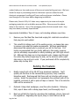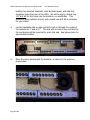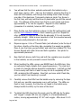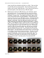
1
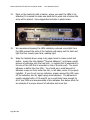
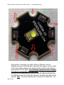
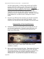
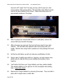
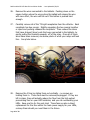
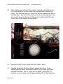
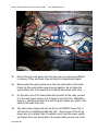
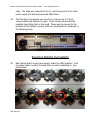
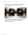
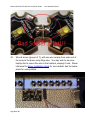
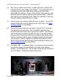
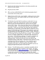
Red Sea Max 250 LED Retrofit Installation Guide - Last Updated 4/29/14
Congratulations on your purchase of a Steve’s LEDs retrofit kit! Please read
through this entire installation guide before unpacking your retrofit kit.
This kit assumes you have a basic knowledge of electronics, such as never touching a live electrical circuit under
any circumstances whatsoever, understanding polarity, wiring in series and parallel, electrical safety and handling,
and the use of basic handheld tools. Consider researching the internet or asking a friend if you are unfamiliar with
these terms. Please read all of the installation related documents such as the Terms and Conditions, Driver
Installation guide, and the LED installation guide before proceeding with building your kit. We are not responsible
for mistakes published in this guide, or installation errors as a result of mistakes published in this installation guide,
you are ultimately responsible for proper and safe installation. By proceeding with the installation, you are
accepting full responsibility of the safe and proper installation of your LED retrofit kit. Remember that your biggest
resources are your friends that are familiar with electronic device installation. Steve’s LEDs is available for support
during normal business hours.
WARNING: The biggest safety issue regarding this kit is not proper wiring, it is taking the appropriate precaution to
always wash your hands after handling the LED retrofit components. Most of the components contain leaded
solder, which has been known to cause a numerous health issues. Here it is: WARNING: This product contains
lead, a chemical known to the State of California to cause neurological damage, cancer and birth defects or other
reproductive harm.
LEAD IS GOOD!!! We use leaded solder because it requires a relatively low temperature to melt. The lower the
temperature we can keep our electronics and LEDs, the longer they last. I have heard of many people getting very
poor lifespan out of LEDs that have been soldered with lead-free solder (almost double the melting temperature of
lead solder). Once installed, you will not be handling your retrofit kit regularly, so it is not a health risk for you to
handle during day-to-day usage. Frankly, if I see an LED related product that is soldered with lead free solder, I
just don’t buy it because chances are that it will have reduced lifespan.
This guide is just that….a guide. There are many ways to install an LED retrofit
system correctly. This guide serves as an outline, based on our years of
experience, of the most efficient, safest, and most economical way to install your
kit.
Before unpacking your retrofit kit from the box, please be aware that mishandling
the LEDs is the #1 cause of permanent damage to the system. Putting a mere 2
ounces of pressure in the wrong spot can tear apart a fragile high power LED or
rip apart essential wiring. Be prepared to treat all of the components as if they
are as fragile as eggs while unpacking. The unpacking process should not be
Page 1 of 19
Red Sea Max 250 LED Retrofit Installation Guide - Last Updated 4/29/14
rushed; take your time and ensure all items are treated with great care. We have
listed the steps in painstaking detail so that even a person unfamiliar with
electronic component handling will have a safe and proper installation. Please
read though all of the steps before beginning installation.
Please note, Steve’s LEDs, LLC takes every opportunity to reuse and recycle
packaging materials such as bubble wrap and filler. We are proud to reduce
waste in this manner. Sorry if the packaging materials look second hand….they
may have been previously experienced!
Approximate Installation Time: 2 hours, not including adhesive cure time.
1.
Remove your Red Sea Max hood and unplug ALL electrical connections
that plug into wall outlets!
2.
This retrofit kit utilizes much of the existing wiring, so please take care
to remove only what this guide recommends. We have painstakingly
determined the easiest way to construct your kit for this tank. It is
highly recommended that you strictly adhere to this guide, however,
you are ultimately responsible for safely installing your LED light retrofit
kit. Although the steps are in chronological order, please read through
the entire step before beginning the step, as the contents within each
step may or may not be in order. If you purchased a 90% complete kit,
please skip to step #18.
Building the Heatsink
1.
Briefly inspect both of the 29.25” long aluminum heatsinks. You’ll
quickly see that due to the manufacturing process, many cosmetic
blemishes exist. Rest assured that these will not interfere with proper
cooling. Select the smoothest (not necessarily the prettiest) side of the
heatsink, and mark it with a piece of tape or marker. This is the side the
LEDs will be mounted to.
2.
Optional: Using black sandpaper, sand the entire heatsink. Following
that, wipe it down with a damp paper towel, and thoroughly dry it.
3.
Next we will drill the holes for mounting the heatsinks, drivers, fans and
fan regulators. Regarding the layout, keep in mind that we will be
Page 2 of 19
Red Sea Max 250 LED Retrofit Installation Guide - Last Updated 4/29/14
building two identical heatsinks, with identical layout, with the only
exception being the color of the LEDs. We will be using a brand new
1/8” drill bit for ALL holes into the heatsink, no substitutes. This
aluminum alloy heatsink is hard, and a brand new drill bit is necessary
for your safety.
4.
Lay the heatsinks side by side and drill a hole in through the center of
the heatsink at 1” and at 17”. The end with no hole is the end that the
fan and drivers will be mounted to, mark this end. See below photo for
approximate location.
5.
Place the driver underneath the heatsink, as shown in the previous
photo below.
Page 3 of 19
Red Sea Max 250 LED Retrofit Installation Guide - Last Updated 4/29/14
6.
You will see that the driver extends underneath the heatsink only a
short ways, approx. 3/8”. Flip over the heatsink, ensuring the driver is
flush with the heatsink, drill through the existing driver holes through
one side of the aluminum. Temporarily placing a single Torx Screw in
the first hole, will help hold the driver in place while you drill the second
hole. The distance of the driver from the fan is not crucial; just leave
approximately 2” for the fan regulator. Repeat for other heatsink
(remember it is identical, holes are NOT mirrored!).
7.
Place the fan over the heatsink as shown (in the flat configuration) and
use the Fan Installation Guide to finish mounting your fan. Repeat for
other heatsink. It does not affect the fan adversely if it is not mounted
perfectly straight. What is more important is that it is mounted securely
and feels solidly attached to the heat sink.
8.
Dispense approx. 0.2cc of Thermal Paste (not adhesive!) onto the top of
the driver, directly on the shiny side, spreading it as evenly as possible.
Place it over the holes you just drilled, and insert two included T20 Torx
Screws. Repeat with other driver and both regulators. See photo for
approximate placement.
9.
Now that both drivers, both fans and both fan regulators are mounted
to the heatsink, we can proceed to mount the LEDs.
10.
When handling the LEDs, ensure you NEVER touch the LEDs lens, they
are extremely fragile, despite their rugged appearance. The clear lens
is made of a complex silicone derivative encapsulant. I will tell you that
it has a mushy soft feel to it and it is easy to rub it completely off the
LED, rendering the LED useless. Now that you know what it feels like,
you can refrain from touching it yourself.
11.
Carefully remove the LEDs from the bubble wrap by removing the tape
first and very carefully unwrapping over a soft surface. The LEDs are
fixed in trays, however, the trays are not taped to the bubble wrap.
Always handle the LEDs, by the sides of the stars!
12.
To detach the LED stars from the panel, grip the LED star by the edge
and “wiggle” a single LED star very slightly, in a forward/backward
motion, moving approximately 15°-20° each wiggle. After about 10-15
Page 4 of 19
Red Sea Max 250 LED Retrofit Installation Guide - Last Updated 4/29/14
cycles, the LED star will detach with little to no effort. Take your time
for each LED with the remaining LEDs. Place the LED stars on a flat
surface, with the shiny metal side down. Do not stack the LED stars or
pile them together, treat each and every LED with respect.
13.
Decide how you want your LEDs laid out on your heat sink. Do not
apply adhesive yet! It is recommended that you mount the LEDs in
groups (arrays) of 7, end to end, facing the same direction, in similar
orientation, of similar color. This makes wiring simple, reduce wiring
errors, and provides a fast and safe installation. It will also give you
control over the color of your LED lighting system. Interlacing the LEDs
(white-blue-white-blue-white-blue) does not provide any better light
blending or advantage. Since the LEDs will be wired in series with 7
LEDs in each array, the LEDs will be attached in this fashion – positive
of LED-1 to the Negative of LED-2, positive of LED-2 to the negative of
LED-3, then the positive of LED-3 will be wired to the negative of LED4, using a single wire to connect each LED to the next. Knowing this,
orient the LEDs with the positive pad of one LED as close as possible
with the negative pad of the next LED. Mounting them side by side,
saves the trouble of stripping wire - just use bare wire to connect the
LEDs together. This also provides a bit of extra ‘punch’ to increase light
to the bottom of the tank and enhances shimmer. This does not result
in a spotlighting effect. We have found it is best to make one entire
heatsink of white LEDs and the second with all Royal Blue LEDs. For
the remainder of this guide, we will assume you have mounted your
LEDs as recommended. See below photo of recommended LED
orientation.
Page 5 of 19
Red Sea Max 250 LED Retrofit Installation Guide - Last Updated 4/29/14
14.
Mark on the heat sink with a marker, where you want the LEDs to be
attached. It is easiest to make one small dot on each side of where the
array will be placed. See exaggerated red dots in photo below.
15.
We recommend keeping the LEDs relatively centered, since light from
the LEDs nearest the ends of the heatsink will simply exit the tank and
light the floor around your tank, wasting light.
16.
Wipe the heatsink down using a dry paper towel to remove dust and
debris. Locate the tube labeled “Thermal Adhesive”, and place a small
amount of adhesive onto the heat sink - (a volume that is equivalent to
the size of the LED that is mounted on top of the star pad). Too much
adhesive is better than too little. You should see a small amount of
adhesive creep out from under the star, on all sides, when it is properly
installed. If you do not see any adhesive, please remove the LED, wipe
off the adhesive, and try again using more adhesive. The adhesive is
usually supplied with a 10% overfill, so you will likely have enough for
all of your LEDs and accommodate a few mistakes. See below photo for
an example of a proper amount of adhesive and more tips.
Page 6 of 19
Red Sea Max 250 LED Retrofit Installation Guide - Last Updated 4/29/14
More detail on mounting your LEDs: Place an LED star over the
adhesive you put on the heat sink, and place two fingers, one over each
of the shiny solder pads and in a swirling motion (1/8” or less motion),
apply pressure to the LEDs. Be extremely careful that your fingers
to not ever contact the LED lens itself. Continue to apply as much
pressure as you reasonably can until you feel the adhesive spread and
the LED star come into contact the heat sink, typically takes about 8 full
seconds TIP: You cannot get the star too close to the heat sink. You
Page 7 of 19
Red Sea Max 250 LED Retrofit Installation Guide - Last Updated 4/29/14
may feel a slight grinding, or metal to metal contact once the LED is
properly seated, this is what you want! If the swirl motion feels too
lubricated, you may not be applying enough pressure. You will not
damage the star itself by applying too much pressure. At least 10 lbs of
pressure is ideal. When the LED is properly seated, it will feel
“attached” to the heat sink and will be resistant to moving, this is a
good sign that you are mounting them properly. Remember, only apply
enough adhesive for one LED at a time! Working time is about 1
minute.
17.
Once all of your LEDs have been mounted, you must wait an absolute
minimum of 4 hours before you can solder them together. In the
meantime, let’s take apart the hood, and prepare it for the LED retrofit.
Dissassembly of the Hood Enclosure
18.
Unplug the hood from the wall and lift it off of the tank and set in on
your work bench upside down. Remove the clear plastic cover, also
known as the splash shield. Unscrew the front screws with your
fingers, see in photo below.
Lift the splash shield partially up, and it will slide out of the hinges
toward you with no effort. Set the splash shield aside until the
installation is complete.
19.
Next, we will remove the screw-hole plugs. These plugs seal the screws
into the hood. Insert a flathead screwdriver with a 3/16” wide head
into the slot of the plug. Do not twist the screwdriver, this will cause a
cosmetic blemish on the plug, but will not otherwise impact the
effectiveness of it. As you insert the screwdriver into the slot, press
Page 8 of 19
Red Sea Max 250 LED Retrofit Installation Guide - Last Updated 4/29/14
down at a 45° angle “into” the plug, and pry until it pops out. (Use
more pressure than prying action) This may take some effort as some
tend to be more stubborn than others. Please see below photo for
approximate locations of the plugs.
20.
After the plugs are removed and stored in a safe place, remove the
screws that were beneath the plugs.
21.
After all screws are removed, the hood will come apart in two main
sections. This will take some patience and some prying with your
hands. Refrain from using tools if possible as it may damage the hood
seams.
22.
Set the top half aside, we will not make any modifications to this.
23.
Using a pair of quality wire cutters or snippers, cut and remove every
plastic wire tie (zip-tie) that you see holding the bundles of wire
together.
24.
You’ll notice that there are 3 large ballasts, and two smaller ballasts.
The smaller ballasts on the right are for the moonlights and existing
fans – keep those intact.
25.
Remove the 3 larger ballasts by removing the screws. They are held in
place with a single screw on each side.
Page 9 of 19
Red Sea Max 250 LED Retrofit Installation Guide - Last Updated 4/29/14
26.
Remove the wires connected to the ballasts. Pushing down on the
square button where the wire enters the ballast will release the wire
with zero effort, the wire will fall out if the button is pushed hard
enough.
27.
Carefully remove all of the T5 Light receptacles from the reflector. Each
receptacle has two prongs. Slightly squeezing the two prongs together
or apart and pushing releases the receptacle. Then remove the wires
that have stripped (bare) ends that were connected to the ballasts, by
gently pulling the terminal upwards, off of the relay. Once all of those
wires have been removed, see below photo of what your relays will look
like - See photo below.
28.
Remove the 4 fans by sliding them out vertically – no screws are
holding them in. These fans must be removed/unplugged. If they are
left in place, they will actually reduce the flow from the high output
pressurizing fans on your LED heatsinks, and you risk overheating your
LEDs. Save one fan for the next step! These fans are also a direct
replacement for the fans within the main power supply for your LEDs,
so keep them should you need them in the future.
Page 10 of 19
Red Sea Max 250 LED Retrofit Installation Guide - Last Updated 4/29/14
29.
After selecting one of those fans you just removed, preferably the one
in the best shape of the four, slide it into the slot that is nearest the
relays. This will help keep your relay cool, without impeding the flow of
the other fans. See red circle in below photo for proper placement. The
fan needs to blow into the hood. Make sure it is fully seated! Plug the
fan into one of the original fan connectors.
30.
Remove the two screws holding the timer plate in place.
31.
Carefully hinge back the timer plate to expose the wiring. Find a
suitable place to mount the dimmer knobs if this is where you would
like them mounted. Drill ¼” holes into the plastic, and mount the
knobs, and run the leads out with approximately 40” of 24ga lead wire.
Page 11 of 19
Red Sea Max 250 LED Retrofit Installation Guide - Last Updated 4/29/14
32.
Now locate the main power supply power cord (thick black) that was
included with your kit. The ‘hot’ (black or blue wire) and the ‘neutral’
(brown or red wire), will use the included blade connectors. The ground
wire will have a butt connector on the ground wire. Use a crimper to
secure them to the ends as shown below.
33.
Drill a ¼” hole next to the existing power wire entrance, and feed the
wire end you just made through that hole. The end with the connectors
will be plugged into a relay, and the other end will plug into the main
power supply unit below the tank. On the main power supply, white =
“N,” black = “L,” and green = “
.”
34.
Route the cord ends with the connectors on them through the timer
box, and plug them into the first relay, as shown circled in the following
photo.
Page 12 of 19
Red Sea Max 250 LED Retrofit Installation Guide - Last Updated 4/29/14
35.
Ensure the plug ends going onto the relay are very secure and difficult
to remove, if they are loose, they will need to be adjusted/crimped.
36.
Disconnected the green/yellow wire from the metal plate in the hood.
Crimp the the green/yellow ground wires together, do not allow the
green/yellow wire to be exposed to anything else except each other.
37.
On the other end of the black cable that connects to the relay, connect
it to the main power supply unit, tinning the wire tips first. Black/Blue
goes to L, white/brown goes to N and the green/yellow wire goes to the
symbol that looks like a tree.
38.
The main power supply unit will not fit into the RSM250 hood, thus, it
will need to be mounted beneath the tank. Run two pair of the 22 ga
power wire (or a single 22ga 4 conductor wire) from the power supply,
up through the hood, along side of the power cable you just ran to the
Page 13 of 19
Red Sea Max 250 LED Retrofit Installation Guide - Last Updated 4/29/14
relay. The 22ga wire connects to the V+ and Comm ports of the main
power supply unit and will power the LED drivers.
39.
The final step to preparing your hood is to remove only 4 of the 9
screws holding the reflector in place. These screws will prevent the
heatsink from sitting flush in the hood. Please see the arrows for the
locations of the reflector screws, which are underneath the heatsinks in
the following photo.
Resuming Building the Heatsink
40.
Now that at least 4 hours have passed, solder the LEDs together. First
tin (place solder) on all of the pads that you will be soldering to. See
photo below.
Page 14 of 19
Red Sea Max 250 LED Retrofit Installation Guide - Last Updated 4/29/14
41.
Now strip the sheath from a considerable length of wire, approximately
4 feet, of 24ga wire. Solder small segments, connecting the LEDs
together. See photo below.
42.
Ensure that the small connecting wire is completely covered in solder as
in previous photo. A wire that is partially exposed presents a fire
hazard, this is known as a cold solder joint. See below photo for an
IMPROPER solder joint example.
Page 15 of 19
Red Sea Max 250 LED Retrofit Installation Guide - Last Updated 4/29/14
43.
Wire all arrays (groups of 7), with one wire coming from each end of
the array to the driver using 24ga wire. You may wish to use wireties/zip-ties to secure the wire to the heatsink, keeping it neat. Please
reference the Driver Installation Guide for more details. See the below
photo for wiring details.
Page 16 of 19
Red Sea Max 250 LED Retrofit Installation Guide - Last Updated 4/29/14
44.
After wiring all LEDs to the drivers, carefully place the completed LED
heat sink into the hood, inside of the reflector. You should see that the
mounting holes that you drilled earlier match up with the braces
underneath the reflectors. Using a 1/16” drill bit, drill through the heat
sink mounting holes and through the hood reflector braces – these are
pilot holes for your mounting screws. Mount the heatsinks to the hood
using the supplied stainless steel 1.5” screws.
45.
Find the wires to the dimmer knobs that were run earlier. Trim off the
excess and plug them into the dimmer ports on the driver. See Driver
Installation Guide for more details.
46.
Find the 22 ga wires that were run earlier. Strip off 3/16” of the end.
This end will go into the driver. Prior to inserting it into the driver,
connect the fan lead wire to the 22 ga wire first. NOTE: The maximum
size wire the driver connector can take is 22 ga, so you cannot solder
the ends of the 22 ga wire and the fan wire side by side (twisting them
together) and insert into the driver, the driver terminal will not grab it.
You may wish to splice it together at a different spot along the wire.
Plug in the 22 ga wires into the driver in their respective locations. See
Driver Installation Guide for more details.
47.
OPTIONAL STEP: To maximize airflow, look up the end of one heatsink,
you will see a flange of plastic directly in the path of the heatsink
exhaust – cut this flange out. You can slide out the fan grill vertically to
get to the flange. See flange circled in below photo.
Page 17 of 19
Red Sea Max 250 LED Retrofit Installation Guide - Last Updated 4/29/14
48.
Double check all electrical connections; one wrong connection can
destroy the entire system.
49.
Plug the unit into a GFCI.
50.
After you have verified that the unit is functioning properly place 2
screws back into the timer panel.
51.
Replace the top of the hood, screw together, replace screw cover plugs,
and replace the clear cover (splash shield) over the LEDs, and ensure
that the seal is good.
52.
To determine how much light to provide your corals with, it is very
important to watch your corals and their response to the LED light.
Start off at less than half dimmed down, and see how the polyps
respond after 5 days. If the polyps are balloon like and relatively clear,
they need more light. If they are small and dark, they are getting too
much light. If they are pure white, they likely have been bleached
(blasted with too much light), and will take about 3 months to recover
using a 30-40% light level. If they appear to be relatively normal, just
let them adjust to the LED spectrum for another 3-5 days. After that,
increase the intensity of the LEDs approx. 2-3% once every 3-4 days (or
1% every day) over the course of the next 2 months. If you rush this
process, it is highly probably that you will bleach and could even kill
your corals. Corals will take a minimum of 6 weeks to acclimate and
adjust to the new brighter LED light after you have completed
acclimating them. During this time their colors will enhance and
sometimes change as they adapt. Sometimes browns will turn to blues,
sometimes blues will turn to greens, etc. Every individual coral is
somewhat unique and as it adapts its colors may change. When
introducing new corals, you must restart this acclimation process, by
bringing the light intensity down to less than half.
53.
Optional - This LED lighting system is completely compatible with all
popular automated aquarium controllers on the market. We highly
recommend getting the Typhon LED Controller. There is no upgrade
that costs less that has such an amazing impact on your aquarium. It is
a simple light controller that allows you to simulate silky smooth
sunrises and sunsets. You can independently control up to 4 separate
Page 18 of 19
Red Sea Max 250 LED Retrofit Installation Guide - Last Updated 4/29/14
channels or color arrays of LEDs. You get to choose the dimming
duration, sunrise, sunset and intensity levels of each color right from
the on-screen backlit LCD display. Using this LED controller has many
other benefits. Since it simulates what the fish and corals experience in
the ocean, it encourages feeding responses, lowers stress levels,
increases immune systems, eliminates fish heart-attacks (cause by
instant on lights) and allows for faster acclimation of newly introduced
species. The only soldering required for installation on the Typhon is to
solder the extension wires. If you do not want to solder anything, then
you will want the Typhon extension, which is pre-soldered (assured to
be wired correctly!) for your convenience, and allows the total
installation time to be approximately 45-60 seconds. Please see the
Typhon page for more details. Using any other controller may require
the Steve’s LEDs Aquarium Controller Interface. Steve’s LEDs
recommends the Neptune Systems AquaController Apex and the Digital
Aquatics ReefKeeper. We highly recommend using the Typhon, even if
you have another aquarium controller.
Page 19 of 19