1
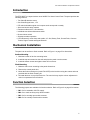
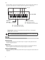
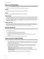
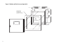
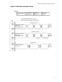
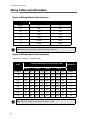
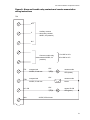
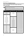
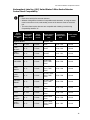
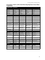
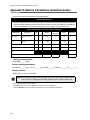
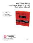
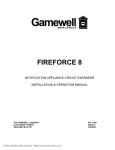
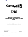
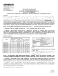
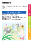
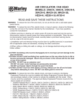
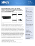
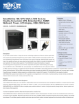
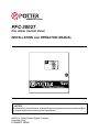
PFC-3002T
Fire Alarm Control Panel
INSTALLATION and OPERATION MANUAL
L NOTICE
All information, documentation, and specifications contained in this manual are subject
to change without prior notice by the manufacturer.
©2004 by Potter Electric Signal Company
November 2004
LT-514POT REV.0
PFC-3002T Installation and Operation Manual
Contents
List of Figures..........................................................................................................................
Introduction .............................................................................................................................
Mechanical Installation ...........................................................................................................
Function Selection ..................................................................................................................
Wiring .......................................................................................................................................
Detection Zone.....................................................................................................................
Signal Zone ..........................................................................................................................
Alarm and Trouble Relays....................................................................................................
Remote Annunciation...........................................................................................................
A.C. Power and Batteries.....................................................................................................
Trouble Indicators and Controls............................................................................................
Common Trouble LED .........................................................................................................
Buzzer/Buzzer Silence Switch .............................................................................................
Zone Trouble LED................................................................................................................
Battery Fault LED.................................................................................................................
Ground Fault LED ................................................................................................................
Signal Trouble LED ..............................................................................................................
Sequence of Operation ...........................................................................................................
Normal..................................................................................................................................
Alarm....................................................................................................................................
Signal Silence ......................................................................................................................
Reset/Lamp Test..................................................................................................................
System Checkout ....................................................................................................................
Power up and Troubleshooting .............................................................................................
Wiring Tables and Information...............................................................................................
Appendix A: Compatible Devices ..........................................................................................
Underwriter’s Laboratories Canada (ULC) Canadian 2-Wire Smoke Detector
Control Panel Compatibility..................................................................................................
Underwriter’s Labs Inc. (ULI) United States 2-Wire Smoke Detector
Control Panel Compatibility..................................................................................................
Underwriter’s Labs Inc. (ULI) United States Signaling Device Control Panel Compatibility.
Appendix B: Battery Calculations (Selection Guide)...........................................................
Warranty...................................................................................................................................
ii
1
1
1
2
2
2
2
3
3
3
3
3
3
3
3
3
4
4
4
4
4
4
4
8
10
10
11
13
14
15
i
List of Figures
List of Figures
Figure 1: Backbox and flush trim mounting details ....................................................................
Figure 2: Circuit Board Layout ...................................................................................................
Figure 3: Detection and signal wiring.........................................................................................
Figure 4: Wiring table for detection zone ...................................................................................
Figure 5: Wiring table for bells and horns ..................................................................................
Figure 6: Alarm and trouble relay contacts and remote annunciation wiring instructions ..........
ii
5
6
7
8
8
9
PFC-3002T Installation and Operation Manual
Introduction
The PFC-3002T is a supervised two-zone 24VDC Fire Alarm Control Panel. The panel provides the
following features:
• Two Class B detection zones
• One Class B signal zone, 1.7A
• DIP switch selectable signal circuit outputs such as temporal or steady
• Alarm and trouble relay contacts
• Remote trouble and A.C. ON indication
• Individual zone silence/disconnect switch
• Buzzer silence switch
• Subsequent alarm operation
• LED indicators for zone alarm and trouble, A.C. On, Battery Fault, Ground Fault, Common
Trouble, Signal Trouble and Signal Silenced
Mechanical Installation
The panel can be surface or flush mounted. Refer to Figure 1 on page 5 for dimensions.
Surface Mounting
1. Mark the location of the four mounting holes.
2. Install the top two screws into the wall and place the panel over the screws.
3. Install the bottom screws and tighten down all four screws.
Flush Mounting
1. Make the wall cut-out according to the panel dimensions.
2. Remove the control panel door.
3. Mount the flush mounting trim (model FA-102TR) to the back box using the screws and nuts
provided with the flush mounting kit.
4. Re-install the door on top of the flush trim. The cam lock may require a minor adjustment in
order to compensate for the flush trim.
Function Selection
The following jumpers are available for function selection. Refer to Figure 2 on page 6 for location.
• JW1: Cut for resettable +24V DC supply.
• JW2: Cut to make auxiliary relay disconnectable.
• JW3: Cut for normally open trouble contacts.
• JW4: Cut for normally closed trouble contacts.
1
Wiring
DIP switch DSW1 is used to set the preferred signal zone 1 output, the signal silence inhibit, and
the common trouble flash rate. The default output for the signal zone is temporal code.
not used
ON
DIP switch DSW1
1
2
3
4
5
6 7
8
Signal Zone
Trouble Buzzer and LED
ON - steady
OFF - temporal code (default)
ON - steady buzzer and LED
OFF - Pulsing Buzzer and LED (default)
ON - 1 minute signal silence inhibit
OFF - normal signal silence (default)
• Temporal Code: 3 rounds of 0.5 second ON, 0.5 second OFF, then 1.5 second pause.
• Steady: Signal on continuously.
Note: Any time the DIP switches in DSW1 are positioned (ON or OFF), the panel must
be reset by holding the Reset button for 5 seconds.
Wiring
Detection Zone
The system has two detection zones. Refer to Figure 3 on page 7 for wiring instruction and to
Figure 4 on page 8 for wire size.
Signal Zone
There is one signal zone available for bells and horns providing 1.7A of signal power. Refer to
Figure 3 on page 7 for wiring instruction and to Figure 5 page 8 on for wire size.
Alarm and Trouble Relays
Alarm and trouble relay contacts are provided. Refer to Figure 6 on page 9 for contact location and
designation.
2
PFC-3002T Installation and Operation Manual
Remote Annunciation
Annunciation outputs are provided for remote trouble indicator and buzzer. Refer to Figure 6 on
page 9 for wiring instruction.
A.C. Power and Batteries
The A.C. power is connected to the terminal block above the transformer.
Use Gel Cell or Sealed Lead-Acid type of batteries only. Connect the batteries after power up. Use
24V 4AH batteries for 24 hours standby and 5 or 30 minutes of alarm. For greater accuracy, use the
battery calculations chart located in Appendix B on page 14.
ELECTRICAL RATING: 120V, 60Hz, 1A
Trouble Indicators and Controls
Refer to Figure 2 on page 6 for the location of indicators and controls.
Common Trouble LED
The yellow Common Trouble LED will flash and the buzzer will sound for any trouble in the panel
(unless DSW1-8 is ON, then the Common Trouble LED will illuminate steadily and the buzzer will
sound).
Buzzer/Buzzer Silence Switch
The buzzer will sound intermittently for any trouble. For any alarm in the system the buzzer will
sound steadily. Operating the buzzer silence switch will silence the buzzer. Any subsequent alarm
or trouble will resound the buzzer. Operating the buzzer silence switch OFF normal will sound the
buzzer steadily.
Zone Trouble LED
The yellow Zone Trouble LED will illuminate steadily for an open loop in the zone. Refer to Figure 2
on page 6 for the location of indicators and control.
Battery Fault LED
Battery removal, low voltage and open battery leads will turn on the yellow Battery Fault LED and
the Common Trouble LED.
Ground Fault LED
Any ground fault of 10K ohms or less will turn on the yellow ground fault LED steadily, flashing the
Common Trouble LED and sounding the common trouble buzzer intermittently.
Signal Trouble LED
The yellow Signal Trouble LED will illuminate steadily for any open or short. (The LED is located
behind the display plate.)
3
Sequence of Operation
Sequence of Operation
Refer to Figure 2 on page 6 for the location of indicators and controls.
Normal
All indicators are normally OFF except for the green A.C. On LED.
Alarm
A red zone alarm LED will illuminate steadily for an incoming alarm.
Signal Silence
If the 60 second signal silence inhibit is selected, the signal cannot be silenced for 60 seconds after
an alarm initiation. Once the 60 seconds have expired, pushing the signal silence switch to the right
will silence all the bells and horns. Once the signal has been silenced, the signal silenced LED will
illuminate. If the switch is in the OFF normal position to the right while there is no alarm condition,
the panel will indicate trouble.
Reset/Lamp Test
Operating the reset switch will restore all latched functions in the panel. The smoke detectors will
reset if all products of combustion are cleared from their chambers. Holding the reset switch for five
seconds will cause the panel to preform a lamp test as well as reset the panel.
System Checkout
Before turning the power on,
1. Check all external wiring for opens, shorts or grounds.
2. Check that transformer cables are securely connected.
3. Check the A.C. power wiring for proper connection. To prevent sparking, do not connect
batteries.
4. Check that all switches are in the normal position to the left.
Power up and Troubleshooting
1. After completing all of the system checkout procedures, power up the panel. The A.C. On LED
should illuminate.The trouble buzzer should sound intermittently, the Common Trouble LED
should flash, indicating battery fault.
2. Connect the batteries carefully, observing the correct polarity.The Common Trouble LED
should extinguish. If the Common Trouble LED stays on, check the front panel for the
illumination of the following LEDs:
• Battery LED indicates that the battery voltage may be too low (below 20.4V).
• Ground Fault LED indicates a ground on one or more of the extended wires.
• Zone Trouble LED indicates an open loop or a signal silence switch is in the OFF normal
position to the right.
• Signal Trouble LED indicates an open loop or short in the signal zone.
4
Figure 1: Backbox and flush trim mounting details
1
11/
13 3/4”
10 3/8”
16”
1 1/ 4”
Optional flush
mounting trim
(model FA-102TR)
7 1/ 8”
12 3/4”
7/
32” dia.
mounting hole
2 7 /8 ”
5
+
-
+
1
+
-
-
JW4
SIGNAL
DETECTION
ZONE
2
1
JW3
COM
(-)
TB2
6
Figure 2: Circuit Board Layout
AUX.
ALARM RELAY
NO C NC
TRBL
RELAY
REMOTE ANNUNCIATION
TRL TRB A.C.
ON
24V
+
BUZZER SIL.
JW1
ZONE 1 SIL.
A.C. ON
JW2
ALARM
TRBL.
ZONE 1
TRBL.
ALARM
TRBL.
ZONE 2
ZONE 2 SIL.
SIG. SIL.
BATT.
F2
GND
2A
A.C.
TRANSFORMER
P1
SIG.1
P2
RESET
ON
BATTERY
F1
2A
1
8
P4
P3
MD-733
DSW1 DIP
SWITCHES
+
BATTERY
-
PFC-3002T Installation and Operation Manual
Figure 3: Detection and signal wiring
Legend
F Pull Station
S
Smoke
Detector
Heat
R Detector
F
Bell
Alarm threshold current is 21 mA.
Maximum loop resistance is 100 ohms.
TB2
+
22VDC 3mA STBY
5mV ripple
50 mA max. alarm
Detection zone 1
F
S
R
ELR
3.9K
1/2W
R
ELR
3.9K
1/2W
Detection zone 2
22VDC 3mA STBY
5mV ripple
50 mA max. alarm
F
S
+
24VDC unfiltered
1.7A max.
Signal zone
F
F
ELR
3.9K
1/2W
-
7
Wiring Tables and Information
Wiring Tables and Information
Figure 4: Wiring table for detection zone
Wire Gauge
Maximum Wiring Run to Last Device (ELR)
(AWG)
ft.
m
22
2990
910
20
4760
1450
18
7560
2300
16
12000
3600
14
19000
5800
12
30400
9200
Note: Maximum loop resistance should not exceed 100 ohms.
Figure 5: Wiring table for bells and horns
Signal circuit is rated for 1.7 amperes each.
Total Signal
Load
Maximum Wiring Run to Last Device (ELR)
18AWG
16AWG
14AWG
12AWG
0hms
Amperes
ft.
m
ft.
m
ft.
m
ft.
m
Ohms
0.06
2350
716
3750
1143
6000
1829
8500
2591
30
0.12
1180
360
1850
567
3000
915
4250
1296
15
0.30
470
143
750
229
1200
366
1900
579
6
0.60
235
71
375
114
600
183
850
259
3
0.90
156
47
250
76
400
122
570
174
2
1.20
118
36
185
56
300
91
425
129
1.5
1.50
94
29
150
46
240
73
343
105
1.2
1.7
78
24
125
38
200
61
285
87
1.0
Note: Maximum voltage drop should not exceed 1.8 volts.
8
Max Loop
Resistance
PFC-3002T Installation and Operation Manual
Figure 6: Alarm and trouble relay contacts and remote annunciation
wiring instructions
TS2
N.O.
C
Auxiliary common
alarm relay contacts
28VDC, 3A (resistive)
N.C.
Common trouble relay
contacts 28VDC, 3A
(resistive)
TRL
1.5K
unsupervised
24VDC, 50 mA max.
TRB
24VDC, 50 mA max.
A.C. ON
Cut JW4 for N.C.
remote trouble
LED (amber)
1.5K
unsupervised
Cut JW3 for N.O.
1.5K
remote trouble
buzzer
remote AC ON
LED (green)
24V+
24VDC, 250 mA max.
9
Appendix A: Compatible Devices
Appendix A: Compatible Devices
Underwriter’s Laboratories Canada (ULC) Canadian 2-Wire Smoke
Detector Control Panel
Notes:
• Reset time, hold for five seconds minimum.
• Whether mixing different models of compatible smoke detectors, or using the same
model on the same Circuit, total standby current of all detectors must not exceed 3
mA.
Make Model / Base
Make Model / Base
Make Model / Base
Mircom
Cerebrus Pyrotronics
Fenwal
MIR-525
D1-2
PSD-7131/70-201000-001
MIR-525T
D1-3/DB-3S
PSD-7131/70-201000-002
System Sensor
PSD-7131/70-201000-003
1400-A
PSD-7131/70-201000-005
2400-A
Mirtone
PSD-7130/70-201000-001
1451-A/B401B
73471
PSD-7130/70-201000-002
1451-A/B406B
73494
PSD-7130/70-201000-003
2451-A/B401B
73575
PSD-7130/70-201000-005
2451-A/B406B
73495/73486
PSD-7128/70-201000-001
1451DH/DH400A
73495/73487
PSD-7126/70-201000-002
2451-A/DH400A
73595/73486
PSD-7126/70-201000-003
C2W-BA
73595/73497
PSD-7126/70-201000-005
C2WT-BA
73594/73400
PSD-7129/70-201000-000
Edwards
73405/73400
PSD-7125/70-201000-001
6249C
73594/73401
PSD-7126/70-201000-002
6250C
73405/73401
PSD-7125/70-201000-003
6264C
PSD-7125/70-201000-005
6266C
CPD-7021/70-201000-001
6269C
Simplex
CPD-7021/70-201000-002
6270C
2098-9110
CPD-7021/70-201000-003
6269C-003
6270C-003
10
CPD-7021/70-201000-005
PFC-3002T Installation and Operation Manual
Underwriter’s Labs Inc. (ULI) United States 2-Wire Smoke Detector
Control Panel Compatibility
Notes:
• Reset time, hold for five seconds minimum.
• Whether mixing different models of compatible smoke detectors, or using the same
model on the same circuit, total standby current of all detectors must not exceed 3
mA.
• The below-listed smoke detectors are compatible with initiating circuits having
Compatibility Identifier "A".
Smoke
Detector
Make Model /
Base
Compatibility
Identifier
Head / Base
Rated
Standby
Current
System Sensor
Smoke Detector
Make Model /
Base
Compatibility
Identifier Head /
Base
Rated Standby
Current
Sentrol - ESL
1100
A - N/A
0.12 mA
429C
S10A - N/A
0.10 mA
1151/
B110LP
A-A
0.12 mA
429CT
S10A - N/A
0.10 mA
1151/
B116LP
A-A
0.12 mA
429CST
S11A - N/A
0.10 mA
1400
A - N/A
0.10 mA
429CRT
S11A - N/A
0.10 mA
1451/B401
A-A
0.12 mA
711U/701E,
701U, 702E,
702U
S10A - S00
0.10 mA
1451/
B401B
A-A
0.12 mA
712U / 701E,
701U, 702E,
702U
S10A - S00
0.10 mA
1451/
B406B
A-A
0.12 mA
713-5U / 701E,
701U, 702E,
702U
S10A - S00
0.10 mA
1451DH/
DH400
A-A
0.12 mA
713-6U / 701E,
701U, 702E,
702U
S10A - S00
0.10 mA
2100
A - N/A
0.12 mA
721U / 702E,
702U
S10A - S00
0.10 mA
2100T
A - N/A
0.12 mA
721UT / 702E,
702U
S10A - S00
0.10 mA
2151/
B110LP
A-A
0.12 mA
722U / 702E,
702U
S10A - S00
0.10 mA
2151/
B116LP
A-A
0.12 mA
731U / 702E,
702U, 702RE,
702RU
S11A - S00
0.10 mA
11
Appendix A: Compatible Devices
Smoke
Detector
Make Model /
Base
Compatibility
Identifier
Head / Base
Rated
Standby
Current
System Sensor (cont’d)
Smoke Detector
Make Model /
Base
Compatibility
Identifier Head /
Base
Rated Standby
Current
Sentrol - ESL (cont’d)
732U / 702E,
702U, 702RE,
702RU
2400
A - N/A
0.12 mA
2400TH
A - N/A
0.12 mA
2400AT
A - N/A
0.12 mA
Detection Systems Inc.
2400AIT
A - N/A
0.12 mA
DS250
B - N/A
0.10 mA
2451 /
B401B
A-A
0.12 mA
DS250TH
B - N/A
0.10 mA
2451 /
B406B
A-A
0.12 mA
DS282
B - N/A
0.10 mA
2451 /
DH400
A - N/A
0.12 mA
DS282TH
B - N/A
0.10 mA
2451TH /
B401B
A-A
0.12 mA
2451TH /
B406B
A-A
0.12 mA
2451 / B401
A-A
0.12 mA
2451TH /
B401
A-A
0.12 mA
4451HT /
B401B
A-A
0.12 mA
4451HT /
B406B
A-A
0.12 mA
Mircom
4451HT /
B401
A-A
0.12 mA
MIR-525U
FDT-1
0.10 mA
5451 /
B401B
A-A
0.12 mA
MIR-525TU
FDT-1
0.10 mA
5451 / B401
A-A
0.12 mA
5451 /
B406B
A-A
0.12 mA
(Continued from previous page)
12
S11A - S00
0.10 mA
PFC-3002T Installation and Operation Manual
Underwriter’s Labs Inc. (ULI) United States Signaling Device Control Panel
Compatibility
System Sensor - SpectrAlert
P2415
P2415W
P241575
P241575W
P2475
P2475W
P24110
P24110W
S2415
S2415W
S241575
S241575W
S2475
S2475W
S24110
S24110W
H12/24
H12/24W
MDL
MDLW
AS-2415W-24-FR
AS-241575W-FR
AS-2430W-FR
AS-2475W-FR
AS-24110W-FR
AS-2415C-FW
AS-2430C-FW
AS-2475C-FW
AS-24100C-FW
AH-24-R
AH-24-WP-R
NS-2415W-FR
NS-241575W-FR
NS-2430W-FR
NS-2475W-FR
NS-24110W-FR
NS4-2415W-FR
NS4-241575W-FR
NS4-2430W-FR
NS4-2475W-FR
NS4-24110W-FR
RS-2415W-FR
RSS-241575W-FR
RSS-2415W-FR
RSS-241575W-FR
RSS-2430W-FR
RSS-2475W-FR
RSS-24110W-FR
RSS-2415C-FW
RSS-2430C-FW
RSS-2475C-FW
RSS-24100C-FW
MT-12/24-ULC
MT-24-LS-VFRULC
MT-24-WS-VFR-ULC
AMT-12/24-RULC
AMT-24-LS-VFRULC
MB-G6-24-R
MB-G10-24-R
SM-12/24-R
AVP-4-15-1
AVP-4-15/75
AVP-4-30/75
AVP-4-110-1
GXS-4-15-1
GXS-4-15/75-W
GXS-4-30/75-W
GXS-4-15/75-C
GXS-4-110-1
GX90S-4-15-1
GX90S-4-15/75W
GX90S-4-30/75W
GX90S-4-15/75-C
GX90S-4-110-1
SHG24-15-1
SHG15/75-W
SHG24-30/75-W
SHG24-15/75-C
SHG24-110-1
GOT24
GOS24-15-1
GOS24-15/75
GOS24-15/75
GOS24-30/75
GOS24-110-1
GMH-24
GMS-24-15-1
GMS-24-15/75-W
GMS-24-30/75-W
GMS-24-15/75-C
GMS-24-110-1
WGMS-4/75
Wheelock
DSM-12/24-R
Gentex
Mircom
FH-240R
FH-240W
FHS-240R
FHS-240R/110
FHS-240W
FHS-240W/110
FS-240R
FS-240R/110
FS-240W
FS-240W/110
SDM-240
13
Appendix B: Battery Calculations (Selection Guide)
Appendix B: Battery Calculations (Selection Guide)
Use the form below to determine the required batteries.
IMPORTANT NOTICE
The main AC branch circuit connection for the Fire Alarm Control Unit must provide a dedicated
continuous power without provision of any disconnect devices. Use #12 AWG wire with 600-volt
insulation and proper over-current circuit protection that complies with the local codes.
Power Requirements (All currents are in amperes)
Model Number
Description
Qty
PFC-3002T
Fire Alarm, 2 Det, 1
Sig
X
RTI-1
Remote Trouble
Indicator
X
2-Wire Smoke Detectors
4-Wire Smoke Detectors
X
Standby
Total
Standby
Alarm
Total Alarm
0.076
=
0.135
=
♦
0.035
=
0.035
0.0001
=
* 0.090
X
=
Signal Load (bells, horns, strobes, and
etc.)
Total currents (Add above currents)
=
= 0.090
=
=
Standby
(A)
(B)
Total Current Requirement
ALARM (B)______ Amps.
Battery Capacity Requirement
([STANDBY (A) ______ ] X [(24 or 60 Hours) ________ ]) + ([ALARM (B) ______ ] X [♣Alarm in Hr.] ________) = (C) ________AH
Battery Selection
Multiply (C) by 1.20 to derate battery.
Note: Batteries BT-40 (4.0AH) and BT-80 (8AH) fit into the backboxes; all larger batteries
such as BT-120 (12AH) and the BT-180 (18AH) require an external battery box.
* Assuming three Initiating Circuits in alarm.
♣
♦
14
Use 0.084 for five minutes of alarm or 0.5 for thirty minutes of alarm as a multiplier figure.
Using the MIR-525/U 2-wire smoke detector. See Appendix "A", for other available smoke detectors .
PFC-3002T Installation and Operation Manual
Warranty
Potter Electric Signal Co., manufactured equipment is guaranteed to be free of defects in material and
workmanship for a period of one (1) year from the date of original shipment. Potter will repair or
replace, at its option, any equipment which it determines to contain defective material or workmanship.
Said equipment must be shipped to Potter prepaid. Return freight will be prepaid by Potter. We shall
not be responsible to repair or replace equipment which has been repaired by others, abused,
improperly installed, altered or otherwise misused or damaged in any way. Unless previously
contracted by Potter, Potter will assume no responsibility for determining the defective or operative
status at the point of installation, and will accept no liability beyond the repair or replacement of the
product at our factory authorized service depot.
Potter Electric Signal Company
2081 Craig Road
St. Louis, MIssouri
USA 63146-4161
Phone Toll Free: (800) 325-3936
Fax: (314) 878-7264
Telephone: (314) 878-4321
Web page: www.pottersignal.com
15