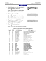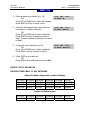
1
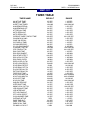
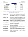
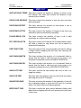
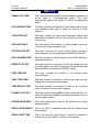
DCS 50si
TECHNICAL MANUAL
MMC: 110
PROGRAMMING
PART 2 NOVEMBER 2000
KEYSET ON/OFF
DESCRIPTION:
Allows the system administrator to set any of the keyset features listed below.
0.
AME BGM
This feature selects whether a station using Answer Machine
Emulation will hear their personal greeting or BGM while
callers are listening to the personal greeting. A BGM source
must be selected for this to work with CADENCE or the
SVMi-4 card.
1.
AME PSWD
If this option is set to YES, station users who have AME set
must enter their station password to listen to messages
being left.
2.
AUTO HOLD
Automatically places an existing C.O. call on hold if a CALL
button, trunk key or trunk route key is pressed during that
call.
3.
AUTO TIMER
Automatically starts the stopwatch timer during a C.O. call.
4.
HEADSET USE
When on, this feature disables the hook switch allowing a
headset user to answer all calls by pressing the ANS/RLS
button.
5.
HOT KEYPAD
When on, this feature allows the user to dial directory
numbers without having to first lift the handset or press the
SPK button.
6.
KEY TONE
Allows the user to hear a slight tone when pressing buttons
on their set.
7.
PAGE REJOIN
Allows the user to hear the latter part of page announcements if his keyset becomes free during a page.
8.
RING PREF.
When off, requires the user to press the fast flashing button
to answer a ringing call after lifting the handset.
PROGRAM KEYS
UP & DOWN
KEYPAD
SOFT KEYS
Used to scroll through options
Used to enter selections
Move cursor left and right
DCS 50si
TECHNICAL MANUAL
PROGRAMMING
PART 2 NOVEMBER 2000
MMC: 110
SPK
HOLD
ANS/RLS
Used to store data and advance to next MMC
Used to clear previous entry
Used to select ALL
ACTION
DISPLAY
1. Press TRSF 110
Display shows
[201] STN ON/OFF
AUTO HOLD :OFF
2. Dial keyset number (e.g., 205)
OR
Press UP or DOWN to select keyset and
press RIGHT soft key to move cursor
OR
Press ANS/RLS for All
[205] STN ON/OFF
AUTO HOLD :OFF
3. Dial option number from above list
(0–5, e.g., 3)
OR
Press UP or DOWN to select option and
press RIGHT soft key to move cursor
[205] STN ON/OFF
AUTO HOLD :OFF
4. Press UP or DOWN to select ON or OFF and
press left or RIGHT soft key to return
to step 3 above
OR
Dial 1 for ON or 0 for OFF
[205] STN ON/OFF
HOT KEYPAD :OFF
[ALL] STN ON/OFF
AUTO HOLD :?
[205] STN ON/OFF
HOT KEYPAD : ON
5. Press TRSF to store and exit
OR
Press SPK to store and advance to next MMC
Dial option number 0 from above list
at step 3
[205] STN ON/OFF
AUTO HOLD :OFF
Dial option number 1 from above list
at step 3
[201] STN ON/OFF
AUTO TIMER :ON
Dial option number 2 from above list
at step 3
[205] STN ON/OFF
HEADSET
:OFF
Dial option number 3 from above list
at step 3
[205] STN ON/OFF
HOT KEYPAD: ON
DCS 50si
TECHNICAL MANUAL
PROGRAMMING
PART 2 NOVEMBER 2000
MMC: 110
Dial option number 4 from above list
at step 3
[205] STN ON/OFF
KEY TONE
:ON
Dial option number 5 from above list
at step 3
[205] STN ON/OFF
PAGE REJOIN:ON
Dial option number 6 from above list
at step 3
[205] STN ON/OFF
RING PREF. :ON
DEFAULT DATA:
AME BGM OFF
AUTO HOLD OFF
AUTO TIMER ON
HEADSET OFF
HOT KEYPAD ON
KEY TONE ON
PAGE REJOIN ON
RING PREFERENCE ON
RELATED ITEMS: MMC 301 ASSIGN STATION COS
MMC 701 ASSIGN COS CONTENTS
CADENCE AME FEATURE
DCS 50si
TECHNICAL MANUAL
MMC: 207
PROGRAMMING
PART 2 NOVEMBER 2000
ASSIGN VM/AA PORT
DESCRIPTION:
Allows technician to change a “NORMAL” SLI ports to a VMAA port. VMAA ports will
receive inband signalling digits designated in MMC 726 (VM/AA Options) and will
also receive a true disconnect signal upon completion of a call. Only SLI boards, not
KDb-SLI, support disconnect signal. Do not set VMAA ports as “data ring” (MMC
208). This will delete inband signalling for voice mail integration. VMAA ports have
the equivalent of data secure written in the program and are always protected
against tones.
NOTE: This MMC is not used to assign CADENCE or SVMi-4 voice mail card ports.
Voice mail card ports are assigned as voice mail ports automatically when the DCS
detects a CADENCE or SVMi-4 card.
PROGRAM KEYS
UP & DOWN
KEYPAD
SOFT KEYS
SPK
HOLD
ANS/RLS
Used to scroll through options
Used to enter selections
Move cursor left and right
Used to store data and advance to next MMC
Used to clear previous entry
Used to select ALL
ACTION
DISPLAY
1. Press TRSF 207
Display shows
[209] VMAA PORT
NORMAL PORT
2. Dial station number (e.g., 205)
OR
Press UP or DOWN to select station
and press RIGHT soft key to move cursor
[205] VMAA PORT
NORMAL PORT
3. Dial 1 or 0 to select port type (1 = VMAA and
0 = NORMAL) OR
Press UP or DOWN to select option
Press RIGHT soft key
[209] VMAA PORT
VMAA PORT
DCS 50si
TECHNICAL MANUAL
PROGRAMMING
PART 2 NOVEMBER 2000
MMC: 207
4. Press TRSF to store and exit
OR
Press SPK to store and advance to next MMC
DEFAULT DATA: NORMAL PORT
RELATED ITEMS: MMC 726 VM/AA OPTIONS
CADENCE CVM8A CARD
SVMi-4 CARD
DCS 50si
TECHNICAL MANUAL
PROGRAMMING
PART 2 NOVEMBER 2000
MMC: 308 ASSIGN BACKGROUND MUSIC SOURCE
DESCRIPTION:
Assigns a background music source to the DCS 50si keysets. There are a total of 5
possible music selections (see below). One music connection is provided on the
KSU motherboard. This source can be switched between internal music source
(chimes) or an external source. A second external source is provided with the
addition of a SMISC card.
You may also select an Auto Attendant (AA) port to provide continuous play of a
specific recording. The AA port selected must be the last port on the SMISC2 card.
If selected, the Music on Hold will be the message defined in MMC 736 from the
port defined in this MMC.
If you have a CADENCE or SVMi-4 Voice Mail System installed you may also select
a voice mail recording as a music source. The recording must already been defined
in MMC 748 and will show up here as the voice mail port associated with the
recording.
OPTIONS
1. NONE: No Background Music.
2. INTERNAL CHIME “OLD FOLKS AT HOME”: This is entered as the directory
number of the music source on the KSU motherboard (3701).
3. EXTERNAL DEVICE: Music Source or Digital announcer. This is entered as the
directory number of an external music source located on the KSU motherboard
(3701) or a SMISC card (3702).
4. DIGITAL ANNOUNCEMENT ON SMISC2 CARD: This is entered as the
directory number of the last AA port of an SMISC2 card (3954).
5. VOICE MAIL SOUND FILE: If the 50si system has an optional CADENCE or
SVMi-4 card installed, up to 100 custom recorded sound files from the Voice Mail
card can be used for BGM sources. Select the voice mail port assigned in
MMC748. For information on creating the sound files see CADENCE/SVMi-4
System Administrator Manual-Recording greetings by number. If you select this
option be advised that VMMOH source requires one dedicated voice mail
port/channel.
DCS 50si
TECHNICAL MANUAL
PROGRAMMING
PART 2 NOVEMBER 2000
MMC: 308
PROGRAM KEYS
UP & DOWN
KEYPAD
SOFT KEYS
SPEAKER
HOLD
ANS/RLS
Used to scroll through options
Used to enter selections
Move cursor left and right
Used to store data and advance to next MMC
Used to clear previous entry
Used to select ALL
ACTION
DISPLAY
1.
Press TRSF 308
Display shows current setting
[201 ] BGM SOURCE
BGM SOURCE:NONE
2.
Dial keyset number (e.g., 205)
OR
Use UP or DOWN to scroll through keyset
numbers; press RIGHT soft key to move cursor
OR
Press ANS/RLS to select all stations
[205 ] BGM SOURCE
BGM SOURCE:NONE
3.
Enter source number (e.g., 3701)
OR
Press UP or DOWN key to make selection and
press RIGHT soft key to return to step 2
[205 ] BGM SOURCE
BGM SOURCE:3701
4.
Press TRSF to store and exit
OR
Press SPK to store and advance to next MMC
[ALL] BGM SOURCE
BGM SOURCE:?
DEFAULT DATA: NONE
RELATED ITEMS: MMC 309 ASSIGN STATION MUSIC ON HOLD
MMC 408 ASSIGN TRUNK MUSIC ON HOLD SOURCE
AUTO ATTENDANT PROGRAMMING
MMC 748 ASSIGN VMMOH
DCS 50si
TECHNICAL MANUAL
MMC: 309
PROGRAMMING
PART 2 NOVEMBER 2000
ASSIGN STATION MUSIC ON HOLD
DESCRIPTION:
This MMC is used to select what MOH source you will hear when another internal
station puts you on hold. There are a total of 5 possible music selections (see
below). One music connection is provided on the KSU motherboard. This source
can be switched between internal music source (chimes) or an external source. A
second external source is provided with the addition of a SMISC card.
In addition to “TONE” or a music source, you may also select an Auto Attendant
(AA) port to provide continuous play of a specific recording. The AA port selected
must be the last port on the card. If selected, the Music on Hold will be the message
defined in MMC 736 from the port defined in this MMC.
If you have a CADENCE or SVMi-4 Voice Mail System installed you may also select
a voice mail recording as a music source. The recording must already been defined
in MMC 748 and will show up here as the voice mail port associated with the
recording.
OPTIONS
1. NONE: No Music on Hold.
2. TONE: A repeated tone is played to the holding party.
3. INTERNAL CHIME “OLD FOLKS AT HOME”: This is entered as the directory
number of the music source on the KSU motherboard (3701).
4. EXTERNAL DEVICE: Music Source or Digital announcer. This is entered as the
directory number of an external music source located on the KSU motherboard
(3701) or a SMISC card (3702).
5. DIGITAL ANNOUNCEMENT ON SMISC2 CARD: This is entered as the
directory number of the last AA port of an SMISC2 card.
6. VOICE MAIL SOUND FILE: If the 50si system has an optional CADENCE or
SVMi-4 card installed, up to 100 custom recorded sound files from the Voice Mail
card can be used for MOH sources. Select the voice mail port assigned in MMC
748. For information on creating the sound files see CADENCE / SVMi-4 System
Administrator Manual-Recording greeting by number. If you select this option be
advised that each VMMOH source requires one dedicated voice mail
port/channel.
DCS 50si
TECHNICAL MANUAL
PROGRAMMING
PART 2 NOVEMBER 2000
MMC: 309
PROGRAM KEYS
UP & DOWN
KEYPAD
SOFT KEYS
SPK
HOLD
ANS/RLS
Used to scroll through options
Used to enter selections
Move cursor left and right
Used to store data and advance to next MMC
Used to clear previous entry
Used to select ALL
ACTION
DISPLAY
1. Press TRSF 309
Display shows current setting
[201 ] MOH SOURCE
MOH SOURCE:NONE
2. Dial keyset number (e.g., 205)
OR
Use UP or DOWN to scroll through keysets
Press RIGHT soft key to move the cursor
OR
Press ANS/RLS to select all stations
[205 ] MOH SOURCE
MOH SOURCE:NONE
3. Enter source number (e.g., 3701)
OR
Press UP or DOWN key to make selection
Press RIGHT soft key to return to step 2
[205 ] MOH SOURCE
MOH SOURCE:3701
[ALL] MOH SOURCE
MOH SOURCE:?
4. Press TRSF to store and exit
OR
Press SPK to store and advance to next MMC
DEFAULT DATA: NONE
RELATED ITEMS: MMC 308 ASSIGN BACKGROUND MUSIC SOURCE
MMC 408 ASSIGN TRUNK MUSIC ON HOLD SOURCE
MMC 748 ASSIGN VMMOH
DCS 50si
TECHNICAL MANUAL
MMC: 408
PROGRAMMING
PART 2 NOVEMBER 2000
ASSIGN TRUNK MUSIC ON HOLD SOURCE
DESCRIPTION:
Allows the System Administrator to select what a trunk caller will hear when that
trunk is placed on hold. There are a total of 5 possible music selections (see below).
In addition to “TONE” or a music source, you may also select an Auto Attendant
(AA) port to provide continuous play of a specific recording. The AA port selected
must be the last AA port on the SMISC2 card (3954). If selected, the Music on Hold
will be the message defined in MMC 736 from the port defined in this MMC.
If you have a CADENCE or SVMi-4 Voice Mail System installed you may also select
a voice mail recording as a music source. The recording must already been defined
in MMC 748 and will show up here as the voice mail port associated with the
recording.
OPTIONS
1. NONE: No Music on Hold.
2. TONE: A repeated tone is played to the outside party.
3. INTERNAL CHIME “OLD FOLKS AT HOME”: This is entered as the directory
number of the music source on the KSU motherboard (3701).
4. EXTERNAL DEVICE: Music Source or Digital announcer. This is entered as the
directory number of an external music source located on the KSU motherboard
(3701) or a SMISC card (3702).
5. DIGITAL ANNOUNCEMENT ON AA CARD: This is entered as the directory
number of the last AA port of an SMISC2 card. For further details on using an AA
port as an MOH source please see MMC 736.
6. VOICE MAIL SOUND FILE: If the 50si system has an optional CADENCE or
SVMi-4 card installed, up to 100 custom recorded sound files from the Voice Mail
card can be used for MOH sources. Select the voice mail port assigned in MMC
748. For information on creating the sound files see CADENCE / SVMi-4 System
Administrator Manual-Recording greeting by number. If you select this option be
advised that each VMMOH source requires a dedicated voice mail port/channel.
DCS 50si
TECHNICAL MANUAL
PROGRAMMING
PART 2 NOVEMBER 2000
MMC: 408
PROGRAM KEYS
UP & DOWN
KEYPAD
SOFT KEYS
SPK
HOLD
ANS/RLS
Used to scroll through options
Used to enter selections
Move cursor left and right
Used to store data and advance to next MMC
Used to clear previous entry
Used to select ALL
ACTION
DISPLAY
1. Press TRSF 408
Display shows current setting
[701 ] TRK MOH
MOH SOURCE:TONE
2. Dial trunk number (e.g., 704)
OR
Use UP or DOWN to scroll through trunks
Press RIGHT soft key to move cursor
OR
Press ANS/RLS to select ALL
[704 ] TRK MOH
MOH SOURCE:TONE
3. Enter source number (e.g., 3701)
OR
Press UP or DOWN key to select option
Press RIGHT soft key to return to step 2 above
[705 ] TRK MOH
MOH SOURCE:3701
[ALL] TRK MOH
MOH SOURCE:?
4. Press TRSF to store and exit
OR
Press SPK to store and advance to next MMC
DEFAULT DATA: TONE
RELATED ITEMS: MMC 308 ASSIGN BACKGROUND MUSIC SOURCE
MMC 748 ASSIGN VMMOH
DCS 50si
TECHNICAL MANUAL
PROGRAMMING
PART 2 NOVEMBER 2000
MMC: 501
SYSTEM TIMERS
DESCRIPTION:
Allows the technician to adjust individual timers as necessary.
NOTE: Certain timers are disabled when the value is “000”.
PROGRAM KEYS
UP & DOWN
KEYPAD
SOFT KEYS
SPK
Used to scroll through options
Used to enter selections
Move cursor left and right
Used to store data and advance to next MMC
ACTION
DISPLAY
1. Press TRSF 501
Display shows first timer value
AA INT DGT TIME
05 SEC →
2. Press UP or DOWN key to select timer and
press RIGHT soft key to move cursor
KMMC LOCK OUT TM
30 SEC → _
3. Enter new value using keypad; if valid, system
returns to step 2 with new value
KMMC LOCK OUT TM
30 SEC → 255
4. Press TRSF to store and exit
OR
Press SPK to store and advance to next MMC
DEFAULT DATA: SEE TABLE OF TIMERS AND VALUES
RELATED ITEMS: NONE
DCS 50si
TECHNICAL MANUAL
PROGRAMMING
PART 2 NOVEMBER 2000
MMC: 501
TIMER TABLE
TIMER NAME
DEFAULT
RANGE
AA INT DGT TIME*
AA NO ACT TIME*
ALERT TONE TIMER
ALM REM.INTERVAL
ALM REM.RING OFF
ATT.RECALL TIME
AUTO REDIAL INT.
AUTO REDIAL RLS.
CADENCE CARD TONE INT TIME
CALLBACK NO ANS
CAMP ON RECALL
CID DISPLAY TIME*
CID MSG RECEIVE*
CO–CO DISCONNECT
CONFIRM TONE TM
CRD TONE INT TM
DIAL PASS TIME
DISA DISCONNECT
DISA DTMF DETECT
DISA LOCK OUT/TM
DISA PASS CHECK
DISPLAY DELAY TM
DOOR LOCK RELES.
DOOR RING DETECT
DOOR RING OFF TM
E-HOLD RECALL TM
EXT.FWD DELAY TM
FIRST DIGIT TIME
HOK FLASH MAX TM
HOK FLASH MIN TM
HOOK OFF TIME
HOOK ON TIME
INQUIRY RELEASE
INTER DIGIT TIME
KMMC LOCK OUT TM
LCR ADVANCE TIME
LCR INTER DIGIT
OFF HOK RING INT
OFF HOOK SELECT
OHVA ANSWER TIME
OVERLAP INT DGT
PAGE TIME OUT
PAGE TONE TIME
PARK RCALL TIME
PC-MMC LOCK OUT
05 SEC
10 SEC
1000 MS
10 SEC
26 SEC
30 SEC
30 SEC
45 SEC
000 SEC
30 SEC
30 SEC
05 SEC
08 SEC
20 MIN
1000 MS
30 SEC
05 SEC
30 MIN
000 SEC
30 MIN
30 MIN
03 SEC
500 MS
50 MS
30 SEC
45 SEC
10 SEC
10 SEC
800 MS
350 MS
200 MS
1000 MS
30 SEC
10 SEC
30 SEC
05 SEC
05 SEC
15 SEC
05 SEC
10 SEC
7 SEC
20 SEC
500 SEC
45 SEC
5 MIN
1–25 SEC
1–25 SEC
100–2500 MS
1–255 SEC
1–25 SEC
1–255 SEC
1–255 SEC
1–255 SEC
001–255 SEC
1–255 SEC
1–255 SEC
1–25 SEC
1–25 SEC
0–255 MIN
100–2500 MS
001–255 SEC
1–25 SEC
1–255 MIN
0-255 SEC
1–255 MIN
1–255 MIN
1–255 SEC
100–2500 MS
10–250 MS
1–255 SEC
0–255 SEC
1–255 SEC
1–255 SEC
0010–2500MS
0010–2500MS
10–250 MS
100–2500 MS
1–255 SEC
10–255 SEC
100–255 SEC
1–255 SEC
1–255 SEC
1–255 SEC
0–255 SEC
1–255 SEC
1–15 SEC
1–255 SEC
100–2500
0–255 SEC
5–60 MIN
DCS 50si
TECHNICAL MANUAL
PROGRAMMING
PART 2 NOVEMBER 2000
MMC: 501
TIMER NAME
POWER DOWN TIME
RECALL DISCONECT
RECALL WAIT TIME
SMDR START/DP
SMDR START/DTMF
SYS HOLD RECALL
TRANSFER RECALL
UCDS AUDIO ALARM*
UCDS VISUAL ALAM*
DEFAULT
RANGE
2000 MS
45 MIN
15 SEC
30 SEC
15 SEC
45 SEC
15 SEC
0 SEC
0 SEC
1000–9000 MS
1–255 SEC
1–255 SEC
1–255 SEC
1–255 SEC
0–255 SEC
0–255 SEC
0–255 SEC
0–255 SEC
NOTE: Timers marked with an asterisk require optional hardware and/or software.
TIMER DESCRIPTIONS
AA INT DGT TIME
When the AA card is installed, this timer determines the
interdigit time for AA call processing. If this timer expires
before valid digits are received by the AA card, the call will
be routed to the AA invalid digits destination.
AA NO ACT TIME
When the AA card is installed, this timer determines the time
that the AA card will wait for a first digit for AA call
processing. If this timer expires before a digit is received, the
call will be routed to the AA no action destination.
ALERT TONE TIMER
This timer sets the duration of the attention tone preceding a
call to a keyset in the Voice Announce or Auto Answer
mode. This tone will also precede a forced Auto Answer call.
ALM REM INTERVAL
This timer controls the time length between ring attempts at
a station when alarm reminder is set.
ALM REM RING OFF
This timer controls the length of the ring cycle duration when
alarm reminder is set at a station.
ATT RECALL TIME
This is the length of time a transfer recall will ring at a station
before recalling the operator.
AUTO REDIAL INT
This timer controls the time between attempts after RETRY
dialing is set on a station.
AUTO REDIAL RLS
This timer controls the duration of a Ring No Answer
condition on a retry number dialed before the auto redial is
automatically canceled.
DCS 50si
TECHNICAL MANUAL
PROGRAMMING
PART 2 NOVEMBER 2000
MMC: 501
CALLBACK NO ANS
This timer controls the time before the callback is
automatically canceled when a callback detects Ring No
Answer.
CADENCE CARD TONE INT TIME
This is the call record tone interval time. An
entry other than zero will cause a tone to be
heard by all the parties in a recorded
conversation. The range for the tone is 001
(every second) to 255 (every 255 seconds). A
value of 000 means no tone.
CAMP ON RECALL
This timer controls the duration of time a camped-on call will
stay at a destination before recalling to the transferring
station.
CID DISPLAY TIME
The amount of time that the Caller ID information remains on
the keyset’s display.
CID MSG RECEIVE
The amount of time that the system will allow a valid
message from the C.O.
C.O.-C.O. DISCONNECT This timer monitors the duration of a unsupervised
conference; when it expires, both trunks are disconnected.
CONFIRM TONE TIME
The tone heard when a feature is activated or deactivated.
CRD TONE INT TM
This is the call record tone interval time. An entry other than
zero will cause a tone to be heard by all the parties in a
recorded conversation. The range for the tone is 001 (every
second) to 255 (every 255 seconds). A value of 000 means
no tone. Requires CADENCE CVM8A card.
DIAL PASS TIME
This timer monitors the duration of the time before
connecting the transmit of an analog station port to the trunk
side of an outgoing call.
DISA DTMF DETECT
This timer sets the time duration that DTMF can be received
on a DISA line.
DISA DISCONNECT
This timer controls the maximum duration of a DISA call.
DISA LOCK OUT TIMER This timer controls the duration of time a DISA call is not
allowed to be made after the DISA error counter has expired
(MMC 500).
DISA PASS CHECK
This timer defines the time period before the system clears
the incorrect passcode counter.
DCS 50si
TECHNICAL MANUAL
PROGRAMMING
PART 2 NOVEMBER 2000
MMC: 501
DISPLAY DELAY TIMER This timer controls the duration a display is shown in the
LCD display. This timer also controls the duration of time
that error tone is heard.
DOOR LOCK RELEASE
This timer controls the duration of time the door lock relay
will be activated.
DOOR RING DETECT
This timer controls the duration of time before a call is
answered by the door phone.
DOOR RING OFF TM
This timer controls the duration of ringing at the door ring
destination before automatically canceling.
E-HOLD RECALL TM
This timer controls the duration of time a call is held
exclusively at a station before recalling.
EXT. FWD DELAY TM
This timer controls the External Call Forward feature which
will allow a station to ring before the call is placed on
external call forwarding.
FIRST DIGIT TIME
This timer controls how long the system will wait for dialing
to begin before dropping the dial tone and returning the
user to error tone.
HOK FLASH MAX TM
This timer monitors the duration of a hookswitch flash to
ensure that the flash is valid and not a line noise or an
accidental hookswitch bounce (LONGEST DURATION).
HOK FLASH MIN TM
This timer monitors the duration of a hookswitch flash to
ensure that the flash is valid and not a line noise or an
accidental hookswitch bounce (SHORTEST DURATION).
HOOK OFF TIME
This timer controls the time before dial tone is sent to a
single line station.
HOOK ON TIME
This timer sets the minimum amount of time that the system
will recognize as an SLT hang up.
INQUIRY RELEASE
This timer monitors the duration of the interaction of the soft
key to determine when to return the LCD back to a normal
status. This timer affects only display phones.
INTER DIGIT TIME
This timer controls the grace period between dialing valid
digits before dropping the call and returning the user back
to error tone.
DCS 50si
TECHNICAL MANUAL
PROGRAMMING
PART 2 NOVEMBER 2000
MMC: 501
KMMC DIGIT TIME
This timer controls the grace period between programming
actions while in a programming session. The timer
automatically returns the system to secure programming
status.
LCR ADVANCE TIME
This timer controls the duration of time before selecting the
next allowable route when a station is allowed to route
advance.
LCR INTER DIGIT
This timer controls the grace period between dialing valid
digits before dropping the call and returning the user back
to error tone.
OFF HOOK RING
This timer controls the duration of time between ring bursts
to a user who has a camped-on call.
OFF HOOK SELECT
This timer controls the grace period before placing a
internal/external call as programmed in MMCs 306 and 307.
OHVA ANSWER TIME
This timer controls the time duration of an OHVA call before
automatic rejection.
OVERLAP INT DGT
This timer controls the amount of time the system will wait
for further digits to be dialed before selecting a BRI channel
when the BRI’s are defined as OVERLAP mode.
PAGE TIME OUT
This timer controls the duration of an external page
announcement.
PAGE TONE TIME
This timer controls the duration of tone burst heard over the
page prior to the page announcement.
PARK RECALL TIME
This timer controls the duration of time a call is parked
before recalling to the call park originator.
PC-MMC LOCK OUT
This timer monitors the PCMMC activity, drops the link if no
action is created by PCMMC and returns the system back to
secure program status.
POWER DOWN TIME
This timer monitors the power to the ROM pack to begin
shutdown status.
RECALL DISCONNECT
This is the time an attendant recall will ring before being
disconnected.
RECALL WAIT TIME
This is the time any recall (hold or transfer) continues to
recall at your station before it recalls to the operator.
DCS 50si
TECHNICAL MANUAL
PROGRAMMING
PART 2 NOVEMBER 2000
MMC: 501
SMDR START/DIAL
PULSE (ROTARY)
the
This grace period timer starts SMDR recording for rotary
dialing. This timer also controls the LCD duration timer on
the keysets. The duration time displayed and the SMDR time
duration will be the same.
SMDR START/DTMF
This grace period timer starts SMDR recording for touchtone
dialing. This timer also controls the LCD duration timer on
the keysets. The duration time displayed and the SMDR time
duration will be the same.
SYS HOLD RECALL
This timer determines the time calls can be left on hold
before recalling back to the holding station. This is a
system-wide timer. Setting timer to 000 will defeat this
feature and no recalling will take place.
TRANSFER RECALL
This timer determines the time transferred calls ring before
recalling. This is a system-wide timer.
UCDS AUDIO ALARM
When an AA card is installed and the digital UCD package
enabled, this counter determines the maximum number of
seconds a call has been waiting at the UCD group before
the UCD group’s SUPV key begins to flash along with an
audio alarm. For more UCD alarm conditions, see MMC 500.
UCDS VISUAL ALARM
When an AA card is installed and the digital UCD package
enabled, this counter determines the maximum number of
seconds a call at the UCD group before the UCD group’s
SUPV key begins to flash as an alarm. For more UCD alarm
conditions, see MMC 500.
DCS 50si
TECHNICAL MANUAL
MMC: 601
PROGRAMMING
PART 2 NOVEMBER 2000
ASSIGN STATION GROUP
DESCRIPTION:
This MMC is used to build all station groups except the operator group (for the
operator group see MMC 600).
The options for setting up these groups are as follows; A thru G.
A. TYPE: This is the type of group you are creating and can be one of the following:
1. NORMAL: Used to assign stations in a ring group. The members can be
stations, common bell contacts or Ring over Page relays.
2. VMAA: Used to group a number of voice mail port extensions. These must
have been defined in MMC 207 as VMAA ports or they cannot be entered
here. Check all programming in MMC 726 to ensure that the In band DTMF
codes are properly set.
3. AA: This is used to group a number of AA ports. An AA card must be
installed in the system to do this.
4. CADENCE: This is the voice mail group for CADENCE / SVMi-4 (the built in
Samsung Voice Mail cards). When a voice mail card is installed, group 529 is
created as a voice mail group.
5. UCD: Used to build a UCD group. The DCS 50si will support two methods of
UCD:
•
TYPE 1 UCD
The group NEXT destination (see below) is defined as an SLT port to
which you must connect some type of announcement device to play to
callers while they are on hold.
Please note that this type of UCD group has the following limitations:
a) The announcement device must be able to terminate the announcement with a hook flash and a transfer back to the UCD group.
b) Only one caller at a time can hear the announcement.
c) Each caller connected to the announcement must hear the announcement in its entirety.
DCS 50si
TECHNICAL MANUAL
PROGRAMMING
PART 2 NOVEMBER 2000
MMC: 601
d) It is possible that a new caller may “jump ahead” in the queue if a
previous caller is currently connected to the announcement device.
•
TYPE 2 UCD
The group NEXT destination (see below) is defined as an AA port or
group. This will only work if an SMISC 2 card has been installed in the
DCS.
The digital announcer in the SMISC 2 card will supply two recorded
announcements to callers in queue. The first announcement is played
only once, the second announcement will repeat for as long as the caller
is in queue.
This type of UCD group has the following advantages:
a) No external device need be installed to provide an announcement.
b) Multiple callers can hear the announcement(s) simultaneously.
c) Callers hearing the announcement will be transferred to a free UCD
group member (agent) as soon as the agent becomes available.
d) The callers place in queue is always maintained.
Additional programming for this type of UCD group is in MMC 607. There
is a maximum of 5 UCD groups available due to availability of system
resources.
B. RING MODE: Each group can have one of the following ring modes. This will
decide how calls are placed to the group.
1. SEQUENTIAL: The stations listed as “members” (see below) will be called
on a first available basis. Calls will first go to the first member, if the first
member is busy, calls will go to the second member, if the first member is
busy, calls will go to the second member etc. This type of group is useful for
placing the bulk of the incoming calls to a selected individual, with other
members only getting the calls when the first member is busy.
2. DISTRIBUTED: The first call will go to the first member, the second call will
go to the second member, the third call will go to the third member. This type
of group is useful for evenly distributing the call among all group members.
3. UNCONDITIONAL: Calls are placed to all group members simultaneously. If
a group member is busy, the can receive off hook ring if defined in MMC 300.
This ring mode option is not available for UCD or VMAA groups.
DCS 50si
TECHNICAL MANUAL
PROGRAMMING
PART 2 NOVEMBER 2000
MMC: 601
C. OVERFLOW: This is a timer value that will cause unanswered calls to a group to
begin also ringing the NEXT PORT ( see below) after this timer has elapsed. If
set to 000, no overflow will take place.
D. GRP TRANSFER: This is a timer that will determine how long C.O. calls
transferred to the group will ring there before recalling. If set to 000, no recall will
take place.
E. NEXT PORT: This is the station or group number that callers will also ring at if
the OVERFLOW feature has been programmed. The NEXT port can be defined
as:
1. COMMON BELL ( DN # 3603 - 3605).
2. RING OVER PAGE ( DN # 3601 - 3605).
F. MEMBER: List all members that are to be in the group. Up to 32 members are
allowed in each group, but stations can be assigned to multiple station groups.
G. WRAP UP: This is only available for UCD groups, and will make a UCD agent
unavailable to receive additional UCD calls after hanging up from the last one.
This is to allow agents to complete work associated with the previous call before
the next call begins ringing.
NOTES: When a group is called, or a caller is transferred to a group, ringback is
sent to the caller. A busy signal will not be returned even if all group members are
busy. Obviously UCD is an exception to this rule.
Calls to a group do not follow the call forwarding instructions of any stations in the
group.
FEATURE KEYS
0
1
2
3
4
5
6
TYPE
RING
OVERFLOW
GRP TRSF
WRAP-UP
NEXT PORT
MEMBER
Group type (Normal, VM/AA, UCD, AA)
Ring mode (Sequential, distributed or unconditional)
Overflow time (000 - 250 secs.)
Group transfer time (000 - 250 secs.)
Wrap-up time (timer only valid in type = UCD)
Overflow port (Any station, common bell or ring over page)
Group members (e.g., station 202, 225, 231)
DCS 50si
TECHNICAL MANUAL
PROGRAMMING
PART 2 NOVEMBER 2000
MMC: 601
RING MODES
0 SEQUENTIAL
The first idle station listed in the group will ring. If the first is
busy, the next idle station will ring.
1 DISTRIBUTED
The first call will ring the first station listed in the group. The
next call will ring the next station listed in the group.
2 UNCONDITIONAL All the stations listed in the group will ring. Busy stations will
receive off-hook ring. MAXIMUM 32 STATIONS RINGING.
PROGRAM KEYS
UP & DOWN
KEYPAD
SOFT KEYS
SPK
HOLD
Used to scroll through options
Used to enter selections
Move cursor left and right
Used to store data and advance to next MMC
Used to clear previous entry
ACTION
DISPLAY
1. Press TRSF 601
Display shows
[501] STN.GROUP
TYPE:NORMAL GRP
2. Dial group number (e.g., 505)
OR
Press UP or DOWN key to select group
Press LEFT soft key to move cursor to type
of group and DIAL group type (0–2, e.g., 1)
OR
Press UP or DOWN key to make selection
Press LEFT soft key to move cursor to TYPE
[505] STN.GROUP
TYPE:NORMAL GRP
3. Dial feature option number (0–6, e.g., 0)
OR
Press UP or DOWN key to make selection
Press RIGHT soft key to move cursor to
ring value
[505] STN GROUP
RING:SEQENTIAL
[505] STN GROUP
TYPE:VMAA
DCS 50si
TECHNICAL MANUAL
PROGRAMMING
PART 2 NOVEMBER 2000
MMC: 601
4. Dial ring option (0–2, e.g., 1)
OR
Press UP or DOWN key to make selection
Press LEFT soft key to move cursor
back to RING or press RIGHT soft key to
return to step 2
[505] STN GROUP
RING:DISTRIBUTE
5. Dial next feature option and continue
OR
Press UP or DOWN key to select option
OR
Press LEFT soft key to return to step 2
[505] STN GROUP
RING:DISTRIBUTE
6. Press TRSF to store and exit
OR
Press SPK to store and advance to next MMC
DEFAULT DATA: NORMAL GROUP
RELATED ITEMS: MMC 203 ASSIGN UA DEVICE
MMC 204 COMMON BELL CONTROL
DCS 50si
TECHNICAL MANUAL
PROGRAMMING
PART 2 NOVEMBER 2000
MMC: 701
ASSIGN COS CONTENTS
DESCRIPTION:
Similar to MMC 700 but does not allow a copy command. This MMC is primarily
used for creating a new class of service. If the unsupervised conference feature is
allowed, a programmed CONF key must be available to allow reentry into a
conference call.
PROGRAM KEYS
UP & DOWN
KEYPAD
SOFT KEYS
SPK
Used to scroll through options
Used to enter selections
Move cursor left and right
Used to store data and advance to next MMC
TOLL LEVEL OPTIONS
DIAL DIGIT
0
1
2
3
TOLL LEVEL
A
B
C
D
DIAL DIGIT
4
5
6
7
ACTION
TOLL LEVEL
E
F
G
H
DISPLAY
1. Press TRSF 701
Display shows
COS CONTENTS(01)
TOLL LEVEL:A
2. Dial COS (e.g., 06)
OR
Press UP or DOWN key to select COS
Press RIGHT soft key to move cursor to toll
level
COS CONTENTS(06)
TOLL LEVEL:A
3. Dial toll level (e.g., 2—see above list)
OR
Press UP or DOWN to select new TOLL level
OR
Press RIGHT soft key to advance to
COS options
COS CONTENTS(06)
TOLL LEVEL:C
DCS 50si
TECHNICAL MANUAL
PROGRAMMING
PART 2 NOVEMBER 2000
MMC: 701
4. Dial COS option (e.g., 09—see Caller ID
option list or Basic option list)
OR
Press UP or DOWN key to select option
Press RIGHT soft key to move cursor
COS CONTENTS(06)
09:DND
:YES
5. Dial 0 for NO or 1 for YES
OR
Press UP or DOWN key to select option
Press LEFT soft key to return to step 4
Press RIGHT soft key to return to step 2
COS CONTENTS(06)
09:DND
: NO
6. Press F key to enter MMC 700 if copy
of COS to another COS is required
Refer to MMC 700 for copying
COPY COS ITMES
COS 01→
→COS 10
7. Press TRSF to store and exit
OR
Press SPK to store and advance to next MMC
Table A. COS Feature List by Option Number
Basic
01
02
03
04
—
—
—
05
06
07
08
09
10
11
12
13
14
15
16
17
18
19
CID
01
02
03
04
05
06
07
08
09
10
11
12
13
14
15
16
17
18
19
20
21
22
LCD Display
AA CALER
ALM CLR
AUTO RDL
CALLBACK
CID ABND
CID INQR
CID INVT
CONFER
DALM CLR
DAY/NIGH
DIRECT
DISA
DND
DOOR
DSS
DTS
EXT FWD
FEATURE
FLASH
FOLOW-ME
FORWARD
GRP I/O
COS Option
Auto answer control by caller*
Alarm sensor ring answer
Retry on busy
Callback
Caller ID Abandon*
Caller ID Inquire*
Caller ID Investigate*
Conference
DISA alarm ring clear
Change day/night mode
Directory dial
Allow DISA use
Do Not Disturb
Door ring answer
Direct station select
Direct trunk select
External call forward
Feature key
Trunk flash
Call forward-follow me
Forward
Group in/out
DCS 50si
TECHNICAL MANUAL
PROGRAMMING
PART 2 NOVEMBER 2000
MMC: 701
Table A. COS Feature List by Option Number
Basic
20
21
22
23
24
25
26
27
28
29
30
31
32
33
34
35
36
37
38
39
40
41
42
43
44
45
46
47
48
49
50
51
52
53
54
55
56
57
58
59
60
61
CID
23
24
25
26
27
28
29
30
31
32
33
34
35
36
37
38
39
40
41
42
43
44
45
46
47
48
49
50
51
52
53
54
55
56
57
58
59
60
61
62
63
64
LCD Display
HOLD
HOT LINE
INTERCOM
MESSAGE
MM PAGE
NEW CALL
OHVAED
OHVAING
ONEA2
OPERATOR
OUT TRSF
OVERRIDE
PAGE 0
PAGE 1
PAGE 2
PAGE 3
PAGE 4
PAGE 5
PAGE 6
PAGE 7
PAGE 8
PAGE 9
PAGE ✱
PICKUP
SECURE
SSPD TOL
STN LOCK
STNGRP 01
STNGRP 02
STNGRP 03
STNGRP 04
STNGRP 05
STNGRP 06
STNGRP 07
STNGRP 08
STNGRP 09
STNGRP 10
STNGRP 11
STNGRP 12
STNGRP 13
STNGRP 14
STNGRP 15
COS Option
Hold
Hot line
Intercom call
Message
Meet me page
New call
Ohvaed
Ohvaing
1A2 emulation
Operator
Outgoing transfer
Overide
Page zone 0 PAGING
Page zone 1 PAGING
Page zone 2 PAGING
Page zone 3 PAGING
Page zone 4 PAGING
Page zone 5 PAGING
Page zone 6 PAGING
Page zone 7 PAGING
Page zone 8 PAGING
Page zone 9 PAGING
Page zone ✱ PAGING
Call pickup
Override secure
System speed dial toll check
Station locking
Station group 01 calling
Station group 02 calling
Station group 03 calling
Station group 04 calling
Station group 05 calling
Station group 06 calling
Station group 07 calling
Station group 08 calling
Station group 09 calling
Station group 10 calling
Station group 11 calling
Station group 12 calling
Station group 13 calling
Station group 14 calling
Station group 15 callling
DCS 50si
TECHNICAL MANUAL
PROGRAMMING
PART 2 NOVEMBER 2000
MMC: 701
Table A. COS Feature List by Option Number
Basic
62
63
64
65
66
67
68
69
70
71
72
73
74
75
76
77
78
79
80
81
82
83
84
85
86
87
88
89
90
91
92
93
94
95
96
97
98
99
CID
65
66
67
68
69
70
71
72
73
74
75
76
77
78
79
80
81
82
83
84
85
86
87
88
89
90
91
92
93
94
95
96
97
98
99
A0
A1
A2
LCD Display
STNGRP 16
STNGRP 17
STNGRP 18
STNGRP 19
STNGRP 20
STNGRP 21
STNGRP 22
STNGRP 23
STNGRP 24
STNGRP 25
STNGRP 26
STNGRP 27
STNGRP 28
STNGRP 29
STNGRP 30
SYS SPD
TRKGRP01
TRKGRP02
TRKGRP03
TRKGRP04
TRKGRP05
TRKGRP06
TRKGRP07
TRKGRP08
TRKGRP09
TRKGRP10
TRKGRP11
UNCO CNF
VMS AREC
VMS AME
VMSSTN01
VMSSTN02
VMSSTN03
VMSSTN04
VMSSTN05
VMSSTN06
VMSSTN07
VMSSTN08
COS Option
Station group 16 calling
Station group 17 calling
Station group 18 calling
Station group 19 calling
Station group 20 calling
Station group 21 calling
Station group 22 calling
Station group 23 calling
Station group 24 calling
Station group 25 calling
Station group 26 calling
Station group 27 calling
Station group 28 calling
Station group 29 calling
Station group 30 calling
System speed dial
Trunk group 01 calling
Trunk group 02 calling
Trunk group 03 calling
Trunk group 04 calling
Trunk group 05 calling
Trunk group 06 calling
Trunk group 07 calling
Trunk group 08 calling
Trunk group 09 calling
Trunk group 10 calling
Trunk group 11 calling
CO to CO conference
Auto Record
Answer Machine Emulator
CADENCE Port 01 calling
CADENCE Port 02 calling
CADENCE Port 03 calling
CADENCE Port 04 calling
CADENCE Port 05 calling
CADENCE Port 06 calling
CADENCE Port 07 calling
CADENCE Port 08 calling
DCS 50si
TECHNICAL MANUAL
PROGRAMMING
PART 2 NOVEMBER 2000
MMC: 701
DEFAULT DATA: ALL VALUES YES EXCEPT 32, 92 AND 93
RELATED ITEMS: MMC 700 COPY COS CONTENTS
MMC 702 TOLL DENY TABLE
MMC 703 TOLL ALLOWANCE TABLE
TOLL RESTRICTION
CADENCE CVM8A CARD
SVMi-4 CARD
DCS 50si
TECHNICAL MANUAL
MMC: 722
PROGRAMMING
PART 2 NOVEMBER 2000
STATION KEY PROGRAMMING
DESCRIPTION:
Allows the customizing of programmable keys on specific electronic keysets, AOM,
or 64 button module on the DCS 50si system. For keysets, buttons 1 and 2 are set
as CALL buttons by default. For AOMs and 64 button DSS boxes all buttons are set
as DS keys by default. Features are entered via dial pad keys by pressing the dial
pad number the required number of steps to select the feature. For example, for
OHVA, the number 6 is pressed three times. If the BOSS key is required, press 2 for
the first letter B and then use the UP or DOWN key to change the selection from
BARGE to BOSS.
DIAL KEYPAD
COUNT→
→
DIAL 2
DIAL 3
DIAL 4
DIAL 5
DIAL 6
DIAL 7
DIAL 8
1
AAPLAY
DICT
GPIK
LCR
MMPA
PAGE
TG
2
BARGE
DICT
HLDPK
LCR
NEW
REJECT
UA
3
CALL
FAUTO
IG
LCR
OHVA
SG
PROGRAM KEYS
UP & DOWN
KEYPAD
SOFT KEYS
SPK
HOLD
Used to scroll through options
Used to enter selections
Move cursor left and right
Used to store data and advance to next MMC
Used to clear previous entry
ACTION
DISPLAY
1. Press TRSF 722
Display shows
[201] KEY (KTS)
01:CALL1 →
2. Enter selected station number (e.g., 205)
OR
Press UP or DOWN key to select station
Press RIGHT soft key to move cursor
[205] KEY (64B)
01:CALL1 →
DCS 50si
TECHNICAL MANUAL
PROGRAMMING
PART 2 NOVEMBER 2000
MMC: 722
3. Enter selected key number (e.g., 18)
OR
Press UP or DOWN key to select key number
Press RIGHT soft key to move cursor
[201] KEY (KTS)
18:NONE →_
4. Using the dial keypad chart, press dial pad
key number to make a selection
OR
Press UP or DOWN key to make a selection
Press RIGHT soft key to advance cursor to
step 5 to enter extender if required or to return
to step 2
[201] KEY (KTS)
18:NONE →GPIK_
5. If required, enter extender (e.g.,03)
OR
Press UP or DOWN key to make a selection
Press RIGHT soft key to return to step 2
[201] KEY (KTS)
18:NONE →GPIK03
6. Press TRSF to store and exit
OR
Press SPK to store and advance to next MMC
DEFAULT DATA: SEE BELOW
RELATED ITEMS: MMC 107 KEY EXTENDER
Default 24 Button Keyset with or without Display
01:CALL1
07:NONE
13:NONE
19:CONF
02:CALL2
08:NONE
14:NONE
20:SPD
03:NONE
09:NONE
15:NONE
21:LNR
04:NONE
10:NONE
16:NONE
22:PAGE
05:NONE
11:NONE
17:NONE
23:CBK
06:TG9
12:NONE
18:NONE
24:MSG
Default 12 Button Keyset
01:CALL1
07:CONF
02:CALL2
08:SPD
03:NONE
09:LNR
04:NONE
10:PAGE
05:NONE
11:CBK
06:TG9
12:MSG
DCS 50si
TECHNICAL MANUAL
PROGRAMMING
PART 2 NOVEMBER 2000
MMC: 722
Default Add-On Module
01:DS
05:DS
09:DS
13:DS
17:DS
21:DS
25:DS
29:DS
02:DS
06:DS
10:DS
14:DS
18:DS
22:DS
26:DS
30:DS
03:DS
07:DS
11:DS
15:DS
19:DS
23:DS
27:DS
31:DS
04:DS
08:DS
12:DS
16:DS
20:DS
24:DS
28:DS
32:DS
Default 64 Button DSS Box
01:DS
05:DS
09:DS
13:DS
17:DS
21:DS
25:DS
29:DS
33:DS
37:DS
41:DS
45:DS
49:DS
53:DS
57:DS
61:DS
02:DS
06:DS
10:DS
14:DS
18:DS
22:DS
26:DS
30:DS
34:DS
38:DS
42:DS
46:DS
50:DS
54:DS
58:DS
62:DS
03:DS
07:DS
11:DS
15:DS
19:DS
23:DS
27:DS
31:DS
35:DS
39:DS
43:DS
47:DS
51:DS
55:DS
59:DS
63:DS
04:DS
08:DS
12:DS
16:DS
20:DS
24:DS
28:DS
32:DS
36:DS
40:DS
44:DS
48:DS
52:DS
56:DS
60:DS
64:DS
Default 7 Button Keyset
01:CALL1
04:NONE
02:CALL2
05:NONE
07:MSG
03:NONE
06:NONE
Programmable Key Assignments
AAPLAY:
AAREC:
ACCT:
ALARM:
AN/RLS:
BARGE:
AUTO ATTND MESSAGE PLAY*
AUTO ATTND MSG RECORD*
ACCOUNT
ALARM RING ANSWER
ANSWER/RELEASE
BARGE-IN
DCS 50si
TECHNICAL MANUAL
PROGRAMMING
PART 2 NOVEMBER 2000
MMC: 722
Programmable Key Assignments
BLOCK:
BOSS:
CALL:
CAMP:
CANMG:
CBK:
CID:
CONF:
CR:
CS:
CSNR:
DICT:
DIR:
DLOCK:
DND:
DP:
DS:
DT:
FAUTO:
FLASH:
FWRD:
GPIK:
HDSET:
HLDPK:
HOLD:
IG:
INQIRE:
ISPY:
LCR:
LISTN:
LNR:
MMPA:
MMPG:
MSG:
MUTE:
NEW:
NIGHT:
NND:
NXT:
OHVA:
OPER:
OHVA BLOCK
BOSS/SECRETARY
CALL BUTTON
STATION CAMP-ON
MESSAGE CANCEL
CALLBACK
CALLER ID*
CONFERENCE
CALL RECORD KEY
CALL STATUS
CALLER ID SAVE NUMBER REDIAL*
DICTATION
DIRECTORY
DOOR LOCK
DO NOT DISTURB
DIRECT PICKUP
DSS KEY
DTS KEY
FORCED AUTO ANSWER
FLASH
CALL FORWARD
GROUP PICKUP
HEADSET MODE
HOLD PICKUP
HOLD
IN/OUT OF GROUP
INQUIRE (CID)*
CID SPY*
LEAST COST ROUTING
GROUP LISTENING
LAST NUMBER REDIAL
MEET ME PAGE ANSWER
MEET ME PAGE
MESSAGE
MUTE
NEW CALL
NIGHT SERVICE
NAME NUMBER DATE (CID)
NEXT (CID)
OFF-HOOK VOICE ANNOUNCE
OPERATOR
DCS 50si
TECHNICAL MANUAL
PROGRAMMING
PART 2 NOVEMBER 2000
MMC: 722
Programmable Key Assignments
PAGE:
PAGPK:
PMSG:
REJECT:
RETRY:
REVW:
SETMG:
SG:
SNR:
SP:
SPD:
STORE:
TG:
TIMER:
UA:
VM:
VMADM:
VMAME:
VMMSG:
VT:
PAGE
PICKUP PAGE HOLD
PROGRAMMED STATION MESSAGE
OHVA REJECT
AUTO REDIAL ON BUSY
REVIEW (CID)*
SET MESSAGE W/O RING
STATION GROUP
SAVED NUMBER REDIAL
UCD SUPERVISOR
SPEED DIAL
STORE DISPLAYED NUMBER (CID)*
TRUNK GROUP
TIMER
UNIVERSAL ANSWER
VOICE MAIL MEMO*
VOICE MAIL ADMINISTRATION*
ANSWER MACHINE EMULATION*
VOICE MAIL MESSAGE KEY*
VOICE MAIL TRANSFER*
NOTE: Items marked with an asterisk require optional hardware and/or software.
DCS 50si
TECHNICAL MANUAL
PROGRAMMING
PART 2 NOVEMBER 2000
MMC: 723
SYSTEM KEY PROGRAMMING
DESCRIPTION:
This MMC is much like MMC 722 Station Key Programming. The main difference is
that this MMC is system-wide rather than on a per-station basis. Features are
entered via dial pad keys by pressing the dial pad number the required number of
steps to select the feature. For example, for OHVA, the number 6 is pressed three
times. If the BOSS key is required, first press 2 for the first letter B and then use the
UP or DOWN key to make the selection from BARGE to BOSS.
NOTE: Please remember that this program is system-wide.
DIAL KEYPAD
COUNT→
→
DIAL 2
DIAL 3
DIAL 4
DIAL 5
DIAL 6
DIAL 7
DIAL 8
1
AAPLAY
DICT
GPIK
LCR
MMPA
PAGE
TG
2
BARGE
DICT
HLDPK
LCR
NEW
REJECT
UA
3
CALL
FAUTO
IG
LCR
OHVA
SG
TYPE OF SET
DIAL
DIAL
DIAL
DIAL
0
1
2
3
24BTNS
12BTNS
32BTNS
7BTNS
PROGRAM KEYS
UP & DOWN
KEYPAD
SOFT KEYS
SPK
HOLD
Used to scroll through options
Used to enter selections
Move cursor left and right
Used to store data and advance to next MMC
Used to clear previous entry
DCS 50si
TECHNICAL MANUAL
PROGRAMMING
PART 2 NOVEMBER 2000
MMC: 723
ACTION
DISPLAY
1. Press TRSF 723
Display shows
SYS.KEY PROGRAM
TYPE:24 BTN SETS
SYS.KEY PROGRAM
2. Enter the type of set via dial pad (e.g., 2)
TYPE:24 BTN SETS
OR
Press UP or DOWN key to make selection and
press RIGHT soft key to move cursor
SYS.KEY PROGRAM
3. Enter key number (e.g., 18)
18:DS →
OR
Press UP or DOWN key to make selection and
press RIGHT soft key move cursor
4. Using the dial keypad chart, press the dial
pad key number to make a selection
OR
Press UP or DOWN key to make a selection
Press RIGHT soft key to advance cursor to
step 5 to enter extender if required
OR
Press LEFT soft key to return to step 3
SYS.KEY PROGRAM
18:DS →GPIK
5. If required, enter extender (e.g.,03)
OR
Press UP or DOWN key to make a selection
Press RIGHT soft key to return to step 2
Press LEFT soft key to return to step 3
SYS.KEY PROGRAM
18:DS →GPIK03
6. Press TRSF to store and exit
OR
Press SPK to store and advance to next MMC
DEFAULT DATA: SEE BELOW
RELATED ITEMS: NONE
Default 24 Button Keyset with or without Display
01:CALL1
07:NONE
13:NONE
19:CONF
02:CALL2
08:NONE
14:NONE
20:SPD
03:NONE
09:NONE
15:NONE
21:LNR
04:NONE
10:NONE
16:NONE
22:PAGE
05:NONE
11:NONE
17:NONE
23:CBK
06:TG9
12:NONE
18:NONE
24:MSG
DCS 50si
TECHNICAL MANUAL
PROGRAMMING
PART 2 NOVEMBER 2000
MMC: 723
Default 12 Button Keyset
01:CALL1
07:CONF
02:CALL2
08:SPD
03:NONE
09:LNR
04:NONE
10:PAGE
05:NONE
11:CBK
06:TG9
12:MSG
Default Add-On Module
01:DS
05:DS
09:DS
13:DS
17:DS
21:DS
25:DS
29:DS
02:DS
06:DS
10:DS
14:DS
18:DS
22:DS
26:DS
30:DS
03:DS
07:DS
11:DS
15:DS
19:DS
23:DS
27:DS
31:DS
04:DS
08:DS
12:DS
16:DS
20:DS
24:DS
28:DS
32:DS
Default 7 Button Keyset
01:CALL1
04:NONE
02:CALL2
05:NONE
07:MSG
03:NONE
06:NONE
Programmable Key Assignments
AAPLAY:
AAREC:
ACCT:
ALARM:
AN/RLS:
BARGE:
BLOCK:
BOSS:
CALL:
CAMP:
CANMG:
CBK:
CID:
CONF:
CR:
CS:
CSNR:
DICT:
DIR:
AUTO ATTENDANT PLAY*
AUTO ATTENDANT RECORD*
ACCOUNT
ALARM RING ANSWER
ANSWER/RELEASE
BARGE-IN
OHVA BLOCK
BOSS/SECRETARY
CALL BUTTON
STATION CAMP-ON
MESSAGE CANCEL
CALLBACK
CALLER ID*
CONFERENCE
CALL RECORD KEY
CALL STATUS
CALLER ID SAVE NUMBER REDIAL*
DICTATION
DIRECTORY
DCS 50si
TECHNICAL MANUAL
PROGRAMMING
PART 2 NOVEMBER 2000
MMC: 723
Programmable Key Assignments
DLOCK:
DND:
DP:
DS:
DT:
FAUTO:
FLASH:
FWRD:
GPIK:
HDSET:
HLDPK:
HOLD:
IG:
INQUIRE:
ISPY:
LCR:
LISTN:
LNR:
MMPA:
MMPG:
MSG:
MUTE:
NEW:
NIGHT:
NND:
NXT:
OHVA:
OPER:
PAGE:
PAGPK:
PMSG:
REJECT:
RETRY:
REVW:
SG:
SETMG:
SNR:
SP:
SPD:
STORE
TG:
TIMER:
UA:
DOOR LOCK
DO NOT DISTURB
DIRECT PICKUP
DSS KEY
DTS KEY
FORCED AUTO ANSWER
FLASH
CALL FORWARD
GROUP PICKUP
HEADSET MODE
HOLD PICKUP
HOLD
IN/OUT OF GROUP
INQUIRE (CID)*
CID SPY*
LEAST COST ROUTING
GROUP LISTENING
LAST NUMBER REDIAL
MEET ME PAGE ANSWER
MEET ME PAGE
MESSAGE
MUTE
NEW CALL
NIGHT SERVICE
NAME NUMBER DATE (CID)*
NEXT (CID)*
OFF-HOOK VOICE ANNOUNCE
OPERATOR
PAGE
PICKUP PAGE HOLD
PROGRAMMED STATION MESSAGE
OHVA REJECT
AUTO REDIAL ON BUSY
REVIEW (CID)*
STATION GROUP
SET MESSAGE W/O RING
SAVED NUMBER REDIAL
UCD SUPERVISOR
SPEED DIAL
STORE DISPLAYED NUMBER (CID)*
TRUNK GROUP
TIMER
UNIVERSAL ANSWER
DCS 50si
TECHNICAL MANUAL
PROGRAMMING
PART 2 NOVEMBER 2000
MMC: 723
Programmable Key Assignments
VM:
VMADM:
VMAME:
VMMSG:
VT:
VOICE MAIL MEMO*
VOICE MAIL ADMINISTRATION*
ANSWER MACHINE EMULATION*
VOICE MAIL MESSAGE KEY*
VOICE MAIL TRANSFER*
NOTE: Items marked with an asterisk require optional hardware and/or software.
DCS 50si
TECHNICAL MANUAL
PROGRAMMING
PART 2 NOVEMBER 2000
MMC: 724
DIAL NUMBERING PLAN
DESCRIPTION:
Provides the access codes and dialing plan needed for the operation of features
and programs. The system comes with a wide range of acceptable numbering plans
set as default and the option to customize the dialing plan. There is also an error
message provided because of the chance of duplicating an access/feature code.
Dialing codes are entered via the dial pad key by pressing the dial pad number the
required steps to select the feature. For example, for OHVA, the number 6 would be
pressed three times. NOTE: Please remember that this program is system-wide.
DIAL KEYPAD
COUNT→
→
DIAL 2
DIAL 3
DIAL 4
DIAL 5
DIAL 6
DIAL 7
DIAL 8
DIAL 9
1
ACCT
DICT
GPIK
LCR
MMPA
PAGE
TG
WCOS
2
BGM
DICT
HLDPK
LCR
NEW
REJECT
UA
WCOS
3
CAMP
FAUTO
IOG
LCR
OHVA
SG
WCOS
PROGRAM KEYS
UP & DOWN
KEYPAD
SOFT KEYS
SPK
HOLD
Used to scroll through options
Used to enter selections
Move cursor left and right
Used to store data and advance to next MMC
Used to clear previous entry
ACTION
1. Press TRSF 724
Display shows
DISPLAY
DIAL NUMBER PLAN
ACCT
:47
→
2. Using the chart, press dial pad key
DIAL NUMBER PLAN
number to make selection
DICT :NONE →_
OR
Press UP or DOWN key to make selection and
press RIGHT soft key to advance cursor
3. Enter digits (e.g., 68) via the dial keypad
DIAL NUMBER PLAN
DICT :NONE →68
DCS 50si
TECHNICAL MANUAL
PROGRAMMING
PART 2 NOVEMBER 2000
MMC: 724
4. Press LEFT soft key to enter change and
continue to make changes
OR
Press RIGHT soft key to enter and return to
step 2; if a error message appears indicating
SAME DIAL EXIST
CHANGE? Y:1,N:0
duplication of access code, enter 1 for YES for SAME DIAL EXIST
CHANGE? Y:1,N:0
change or enter 0 for NO for no change
5. Press TRSF to store and exit
OR
Press SPK to store and advance to next MMC
DEFAULT DATA: SEE BELOW
RELATED ITEMS: ALL PROGRAMS AND FEATURES
ABAND
ACCT
ALM
ALMCLR
AUTH
BARGE
BGM
BLOCK
BOSS
CAMP
CANMG
CBK
CONF
CB
DICT
DIR
DIRPK
DISALM
DLOCK
DND
FAUTO
FLASH
FWD
GRPK
HLDPK
IG
LCR
LISTN
LNR
NONE
47
NONE
57
✱
NONE
3701–3702
NONE
NONE
45
42
44
46
3603–3605
NONE
NONE
65
58
13
40
14
49
60
66
12
53
NONE
NONE
19
MMPA
MMPG
MODEM
MSG
NEW
NIGHT
OHVA
OPER
PAGE
PAGPK
PMSG
REJECT
RETRY
ROP
SETMG
SGP
SNR
SPEED
STN
TGP
TRK
UA
VMSCMT
VMSMSG
VMSOUT
VMSREC
VMSVAC
WCOS
56
54
359
43
NONE
NONE
NONE
0
55
10
48
NONE
NONE
3601–3605
41
500–529
17
16
201–299, 301–349
9, 80–89
701–799
67
NONE
NONE
NONE
NONE
NONE
59
NOTE: Items marked with an asterisk require optional hardware and/or software.
DCS 50si
TECHNICAL MANUAL
PROGRAMMING
PART 2 NOVEMBER 2000
MMC: 727
SYSTEM VERSION DISPLAY
DESCRIPTION:
Used only for system version display. This is a READ ONLY MMC.
PROGRAM KEY
SPK
Used to advance to next MMC
ACTION
DISPLAY
ROM VERSION
1. Press TRSF 727
Display shows software verson on SMEM card ‘99.04.20. V1.1
Press UP or DOWN key to select other
system versions
Basic 8 DLI ports on KSU motherboard
B.DLI VER:B.8DLI
NO VERSION DATA
Optional 2SLI card
O.SLI VER:O.2SLI
NO VERSION DATA
SMISC card. The software version is the
version of the AA software on the SMISC2
MISC. VER:MISC
’98.10.29 V1.0
KSU Expansion slot 1.
SLOT1 VER:3TRK
NO VERSION DATA
KSU Expansion slot 2.
SLOT2 VER:8DLI
NO VERSION DATA
KSU Expansion slot 3. This slot has a 4BRI
card installed
SLOT3 VER:4BRI
’99.04.13 V1.1
CADENCE / SVMi-4
SLOT7 VER:VM
’98.10.02 V1.0
DEFAULT DATA: NONE
RELATED ITEMS: NONE
DCS 50si
TECHNICAL MANUAL
PROGRAMMING
PART 2 NOVEMBER 2000
MMC: 740
VM CARD RESTART
DESCRIPTION:
This MMC is only used for the Samsung Plug In Voice Mail Card.
There are two options available in this MMC:
DOWNLOAD
When the CADENCE / SVMi-4 card starts, part of the power up procedure will
download data from the 50si to determine time, date, what mailboxes to create, and
system numbering plan. This must be done at least once, but once done this
download feature can be turned off to save boot up time.
CARD RESTART
If this option is set to YES the CADENCE / SVMi-4 card will immediately restart
according to the download OPTION SPECIFIED ABOVE.
PROGRAM KEYS
UP & DOWN
KEYPAD
SPK
Changes MMC data between YES and NO
0 and 1 will change data and advance to other option
Used to store data and advance to next MMC
ACTION
1. Press TRSF 740
Display shows
DISPLAY
VM CARD RESTART
DOWNLOAD ? YES
2. Dial 0 for NO to set option and advance
3. Display shows
4. Dial 0 for NO to set option and advance
5. Press TRSF to store and exit
OR
Press SPK to store and advance to next MMC
VM CARD RESTART
CARD RESTART? NO
DCS 50si
TECHNICAL MANUAL
PROGRAMMING
PART 2 NOVEMBER 2000
MMC: 740
DEFAULT DATA:
CARD RESTART: NO
DOWNLOAD: YES
RELATED ITEMS: NONE
DCS 50si
TECHNICAL MANUAL
PROGRAMMING
PART 2 NOVEMBER 2000
MMC: 741
ASSIGN MAILBOX
DESCRIPTION:
This MMC is only used for Samsung Plug In Voice Mail card. It assigns each station
or group as having a mailbox in a specific CADENCE / SVMi-4 group. When stations
or groups are assigned to a CADENCE / SVMi-4 group, during Voice Mail card
power up mailboxes will be created for each directory number with a “YES” entry.
( if MMC 740 is set to DOWNLOAD = YES )
Once the Voice Mail database has been created new boxes can be added:
a) Through Voice Mail administration,
b) By adding a new mailbox in this MMC.
A mailbox can be removed using this MMC only if it was created by this MMC.
A mailbox cannot be removed using this MMC if it was created by CADENCE
administration.
If a station that do not have an associated voice mail box, call the Voice Mail system
they will be answered by the Voice Mail system main greeting.
NOTE: The groups that are supported are 500 to 529 (529 being the Voice Mail
group). Mailboxes that are needed for people that do not have an extension must be
added through Voice Mail programming.
PROGRAM KEY
UP & DOWN
KEYPAD
SPK
Selects station number
Selects station number
Used to store data and advance to next MMC
ACTION
DISPLAY
1. Press TRSF 741
Display shows
[741] ASSIGN MBX
201 : YES
2. Dial station number
OR
Press UP or DOWN to scroll the number
[741] ASSIGN MBX
[225] : YES
DCS 50si
TECHNICAL MANUAL
PROGRAMMING
PART 2 NOVEMBER 2000
MMC: 741
3. Press RIGHT soft key to move cursor
[741] ASSIGN MBX
[225] : YES
4. Enter YES or NO
[741] ASSIGN MBX
[225] : NO
5. Press TRSF to store and exit
OR
Press SPK to store and advance
to next MMC
DEFAULT DATA: ALL STATIONS = YES
RELATED ITEMS: CADENCE CVM8A CARD
SVMi-4 CARD
DCS 50si
TECHNICAL MANUAL
PROGRAMMING
PART 2 NOVEMBER 2000
MMC: 745
VM DESTINATION
DESCRIPTION:
This MMC is only used for the Samsung Plug In Voice Mail card.
This MMC provides an emergency destination for trunk/station calls to group 529. If
the Voice Mail card is removed or is offline.
In addition any calls to a station forwarded to the Voice Mail card will not forward,
they will remain ringing at the “fwd from” station until answered.
The destination can be a station number or a group number. This destination is also
used for the HDD alarm destination (MMC 747).
PROGRAM KEY
UP & DOWN
KEYPAD
SPK
HOLD
Selects destination station number
Selects destination station number
Used to store data and advance to next MMC
Used to delete an entry
ACTION
DISPLAY
1. Press TRSF 745
Display shows
VM DESTINATION
DEST:500
2. Dial station number
OR
Press UP or DOWN to scroll to number
VM DESTINATION
DEST:213
3. Press TRSF to store and exit
OR
Press SPK to store and advance to next MMC
DEFAULT DATA: VOICE MAIL DESTINATION = 500
RELATED ITEMS: MMC 747 DRIVE ALARM
CADENCE CVM8A CARD
SVMi-4 CARD
DCS 50si
TECHNICAL MANUAL
PROGRAMMING
PART 2 NOVEMBER 2000
MMC: 746
VM HALT
DESCRIPTION:
This MMC is only used for the Samsung Plug In Voice Mail card.
This MMC is used to halt the Voice Mail card (take it offline). No calls will be
disconnected, however no new IN/OUT bound calls are established. It ensures that
there is no traffic on the Voice Mail card when it is removed from the system.
NOTE: THIS OPERATION SHOULD BE PERFORMED BEFORE REMOVING THE
VOICE MAIL CARD FROM THE DCS 50si SYSTEM. YOU CAN NOT HALT THE
VOICE MAIL CARD USING MMC 810.
PROGRAM KEY
UP & DOWN
SPK
HOLD
1 = processing, 0 = halt
Used to store data and advance to next MMC
Used to delete an entry
ACTION
DISPLAY
1. Press TRSF 746
Display shows
[746]VM HALT
STATUS:PROC
2. Enter 1 to halt
OR
0 to process to scroll to number
[746]VM HALT
STATUS:HALT
3. Display shows:
Press # to confirm
[746]VM HALT
ARE YOU SURE?:_
4. Display shows:
[746]VM HALT
STATUS:HALTED
5. Press TRSF to store and exit
OR
Press SPK to store and advance to next MMC
DEFAULT DATA: NONE
RELATED ITEMS: CADENCE CVM8A CARD / SVMi-4 – LED INDICATIONS
DCS 50si
TECHNICAL MANUAL
PROGRAMMING
PART 2 NOVEMBER 2000
MMC: 747
VM DRIVE ALARM
DESCRIPTION:
The MMC will generate an alarm message at the destination assigned in MMC 745
whenever the Voice Mail disk drive reaches a predefined threshold.
The threshold is measured in % full. This means that if the MMC is set for 80, the
alarm will be generated when the disk exceeds 80% of the available drive space.
PROGRAM KEY
KEYPAD
SPK
HOLD
Used to enter new threshold value
Used to store data and advance to next MMC
Used to delete an entry
ACTION
DISPLAY
1. Press TRSF 747
Display shows
[747]VM ALARM
THRESHOLD:80
2. Enter new threshold level
[747]VM ALARM
THRESHOLD:75
3. Press TRSF to store and exit
OR
Press SPK to store and advance to next MMC
DEFAULT DATA: 80%
RELATED ITEMS: MMC 745 VM DESTINATION
CADENCE CVM8A CARD
SVMi-4 CARD
DCS 50si
TECHNICAL MANUAL
PROGRAMMING
PART 2 NOVEMBER 2000
MMC: 748
ASSIGN VMMOH
DESCRIPTION:
This MMC is used to assign each a Music on Hold source for the 50si from a sound
file located on the CADENCE hard disk drive or SVMi-4 flash module. The 100
available sound files are defined as numbers 5000 to 5099, but are referred to in this
MMC as 00-99.
Make sure you record the sound file first. The next step is to assign the sound file to
a voice mail port. For example, if you record sound file 5025 you would associate 25
with a specific CADENCE or SVMi-4 port, e.g. 225. This will dedicate the port for use
only as MOH and remove it from group 529. Now 225 will show up as a valid music
source in MMC 308, 309 and 408.
Each Music on Hold source assigned here requires one DEDICATED CADENCE /
SVMi-4 port/channel.
Note: If the first CADENCE / SVMi-4 port is used for VMMOH, it must be disabled
before boot up since CADENCE / SVMi-4 and the 50si use port 1 during boot up to
exchange critical information. For this reason we suggest you use the last port(s) as
VMMOH ports.
PROGRAM KEY
KEYPAD
SPK
HOLD
UP and DOWN
Used to enter voice mail port or sound file number
Used to store data and advance to next MMC
Used to delete an entry
Used to select voice mail port or sound file number
ACTION
DISPLAY
1. Press TRSF 748
Display shows
SET VMMOH
[225] NOT USED
2. Press UP or DOWN to select CADENCE
port
SET VMMOH
[228] NOT USED
3. Move cursor to next field.
Press UP or DOWN to select sound file
SET VMMOH
[228] 25
4. Press TRSF to store and exit
OR
Press SPK to store and advance to next MMC
DCS 50si
TECHNICAL MANUAL
PROGRAMMING
PART 2 NOVEMBER 2000
MMC: 748
DEFAULT DATA: ALL CADENCE PORTS NOT USED FOR SOUND FILE
RELATED ITEMS: MMC 308 ASSIGN BACKGROUND MUSIC SOURCE
MMC 309 ASSIGN STATION MUSIC ON HOLD
MMC 408 ASSIGN TRUNK MUSIC ON HOLD SOURCE
CADENCE CVM8A CARD
SVMi-4 CARD
DCS 50si
TECHNICAL MANUAL
PROGRAMMING
PART 2 NOVEMBER 2000
MMC: 749
VM PORT IN/OUT
DESCRIPTION:
This MMC is used to assign each Voice Mail Port as used for incoming, outgoing or
both way calls. Note that this MMC must be sent to support outgoing calls if off
premises notification (beeper, outbound follow me of outbound notification) is used.
PROGRAM KEY
KEYPAD
SPK
HOLD
Used to enter new value
Used to store data and advance to next MMC
Used to delete an entry
ACTION
DISPLAY
1. Press TRSF 749
Display shows
VM IN / OUT
[225] IN
2. Press UP or DOWN to view options
VM IN / OUT
[225] OUT
3. Press UP or DOWN to select option
VM IN / OUT
[225] OUT
4. Press TRSF to store and exit
OR
Press SPK to store and advance to next MMC
DEFAULT DATA: ALL PORTS IN / OUT
RELATED ITEMS: CADENCE CVM8A CARD
SVMi-4 CARD