1
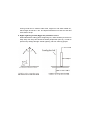
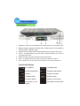
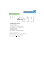
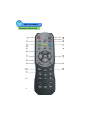
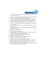
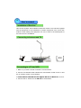
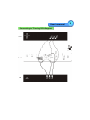
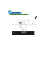
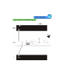
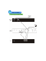
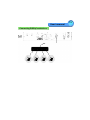
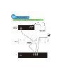
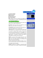
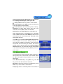
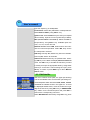
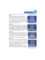
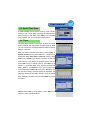
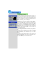
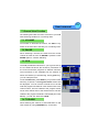
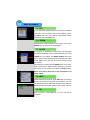
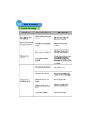
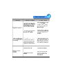
DVB
DBS-5500CI
Owner’s Manual
TRAXIS Corporation
Safety First
Please review the following safety precautions. If
this is the first time you have used a receiver, then
read t his manual before ins talling or using t he
receiver. If the receiver is not functioning properly,
please c ontac t your local dis tributor or sys tem
installer.
The lightning symbol in a triangle is used to alert you to the presence of dangerous voltage inside the receiver that may be sufficient to constitute a risk of
electric shock to anyone opening the case. It is also used to indicate improper
installation or handling of the receiver that could damage the electrical system
in the receiver or in other equipment attached to the receiver.
The exclamation point in a triangle is used to alert you to important operating
and maintenance instructions.Failure to follow these instructions could result in injury to you or damage to t he receiver.
Be careful with electricity:
Power outlet:
To prevent electric shock be sure the elec trical plug used on
the receiver’
s power cord matches the electrical outlet used to
supply power to the receiver. Connect the power cord only to a
power source that operates at 100~240 Volts AC, 50/60 Hz.
Power cord:
Be sure the power cord is routed so that it will not be stepped
on or pinched by heavy it ems.
Power
overloading:
Avoid overloading elec trical outlets or extension cords, which
otherwise could result in electric shock or fire.
Power plug:
If a t hree-prong power plug is provided with t he rec eiver, be
sure it is used with a properly grounded three-wire power
socket.
Light ning:
For protection from lightning, or when the receiver is left unattended for a long period, disconnect it from the power source.
P rotect ot her
equipment:
Unplug t he receiver before connecting any other equipment,
es pecially t he TV antenna connec t all equipment t o t he receiver before plugging any power cords t o the power source.
Power line:
Be s ure your TV antenna is not located near overhead power
lines, or where it might fall int o any power lines. Also be careful to avoid touching any such power lines when installing the
TV ant enna.
Also follow the se precautions:
Ventilation:
Do not bloc k the ventilation slots on the receiver, or place any
heavy object on top of it.
Blocking the air flow could damage the receiver. Arrange components s o that air can flow freely around the receiver.
Ensure t hat t here is adequate ventilat ion if the rec eiver is
placed in a s tand. Put the receiver in a properly ventilat ed
area, away from direct sunlight or any source of heat.
Overheat ing:
Avoid s tack ing the receiver on top of a hot component s uch
as a power amplifier.
Risk Of Fire:
Do not plac e t he rec eiver on top of any easily combus tible
material, suc h as carpet or fabric.
Proper
Connections:
Be sure all cables and equipment are connec ted to the receiver as described in t his manual.
Object Entry:
To avoid electric s hock , never stic k anything in the slots on
the case or remove t he cover.
Wat er
Expos ure:
To reduce the risk of fire or electric s hock, do not expos e the
rec eiver to rain or moisture.
The Way Of Prevent Satellite Receiving
Antenna From Hitting By Mine
Satellite receiving antenna is fit on where is higher, whic h is easily hit by mine.
Mine not only destroys t he device, but also makes a menace to people’
s safety.
So it is very important to fit on lightning rod on antenna.
1. The protection area of lightning rod
O
O
The protection area of lightning rod is 45 ~ 60 pie slice area under lightning rod.
The ant enna will be prot ec ted when it is in the pie s lice area. Higher t he
lightning rod fit . Bigger the protect ion area is. A ntenna must be fit in the protect ion area.
The distance between lightning rod and protected antenna should be more than
5m, because the faradism of lightning rod and its down-lead hit by mine can penetrate 2~3m air.
2. Wood pole lightning rod make and installation
Lightning rod is made up of (lightning rod’
s needlepoint), beanpole, grounded
down-lead and grounded object.
The second image is wool pole beanpole light ning rod. Needlepoint is made
of thicker brass wires and iron wires. The thick iron stick is better.
Beanpole may use wood pole or metal pole.
Grounded down-lead may us e t hic ker iron wires or other metal bar, which
upper part is connected with needlepoint,and its underpart is connected with
grounded object under ground, the connec tion must use jointing. Grounded
down-lead must use a whole wire, and select the shortest distance to connect
with grounded object. Try your best not to make it bend.
Grounded object is metal object under ground, which is usually made of steel
tube, angle iron and st eel needle etc. lts length should be 1~ 2m, and depth
should be more t han 2m. Grounded object of light ning rod can’t be used by
ot her grounded object at the same time. lt must be connect ed with ground
alone.
3. Metal pole lightning rod make and installation
The light ning rod beanpole made of met al pole may us e metal pole t o lead
mine electric c urrent, without any addit ional grounded down-lead. Lightning
rod’s needlepoint is connect ed with metal pole by weld. Grounded object
under ground can be made of steel tube, angle iron and st eel needle et c,
which lengt h should be 1~2m. The depth should be more t han 2m and dust
some salt in the pit.
4. Higher lightning rod fits, Bigger the protection area is.
When selec ted the setting plac e of lightning rod, users should try their best to
keep away from ways and entrances where people oft en pas s by, in order to
prevent step voltage brought around lightning rod from harming people.
Table of Contents
Safety Instructions .....................................................................................1
General Features........................................................................................2
Unpacking .................................................................................................3
General Information...................................................................................3
Front Panel ................................................................................................4
Rear Panel..................................................................................................5
Remote Control Unit ..................................................................................6
Installation of Receiver...............................................................................8
Connecting to Antenna and TV .................................................................8
Connecting to TV using RCA support........................................................9
Connecting to TV using S-VHS Support...................................................10
Connecting to TV using RF support ........................................................11
Connecting to another DVB.......................................................................12
Connecting DiSEqC switch box................................................................13
Connecting to TV using S/PDIF(COAXIAL) Support...............................14
MainMenu......................................................................................................15
1. Easy Tuning...............................................................................................15
2.Installation...................................................................................................16
2.1 Antenna Setting..................................................................................17
2.2 Manual Search....................................................................................19
2.3 Edit Satellite.......................................................................................20
2.4 Edit Transponder................................................................................22
2.5 Factory Default....................................................................................23
3. TV Channels...............................................................................................24
3.1 Edit Channels......................................................................................24
3.2 Set Favourites.....................................................................................26
3.3 Sort Channels.....................................................................................26
4. Radio Channels..........................................................................................27
5. System Setting............................................................................................27
5.1 System.................................................................................................28
5.2 OSD.....................................................................................................28
5.3 Select Time Zone...............................................................................29
5.4 Timer....................................................................................................29
5.5 About STB...........................................................................................30
5.6 Common Interface..............................................................................30
6. Parental Control..........................................................................................32
7. General View Function.............................................................................33
7.1 VOLUME.............................................................................................33
7.2 PAUSE...............................................................................................33
7.3 EPG.....................................................................................................33
7.4 TV/RADIO...........................................................................................33
7.5 SAT......................................................................................................34
7.6 ZOOM.................................................................................................34
7.7 AUDIO.................................................................................................34
7.8 INFO..................................................................................................34
7.9 OK......................................................................................................34
8. Update Software.........................................................................................35
9. Trouble Shooting........................................................................................36
10. Glossary of terms.....................................................................................38
11. Technical Specification.............................................................................41
12. Menu Structure.........................................................................................43
User’s manual
1
Safety Instructions
1.
Be s ure t o read this Us er's Manual before s tarting t he operation of t he
receiver.
2.
Do not open the cover. It is dangerous to t ouch the ins ide of t he receiver
due to possible elec tric haz ard.
3.
Use a soft cloth and a mild solution of washing-up liquid to clean the case.
4.
When t he reciver is unused for a long time, unplug the power cord from the
wall outlet.
5.
Do not connect or modify cables when t he reciver is plugged in.
6.
Do not use a damaged power cord that may cause a fire or an electric shock.
7.
Do not touch a power cord with wet hand. It may cause an electric shock.
8.
When connecting c ables , the receiver must have been powered off.
9.
Ensure a minimum distanc e of 5cm around t he apparat us for s uffic ient
ventilation.
10.
Ensure that t he ventilation is not impeded by covering the vent ilation openings with items, such as newspapers, table-cloths, curtains, etc.
11.
Do not place naked flame sources, such as lighted candles on the apparatus.
12.
Take attent ion to the environmental aspects of battery disposal.
13.
Use t he apparat us only in moderate climates( not in tropical climates)
14.
Do not expose the apparatus to dripping or splashing.
15.
Do not place objects filled with liquids, such as vases, on the apparatus.
The location of the markings is at the bott om of the apparatus.
16.
CAUTION
Danger of explosion if battery is incorrectly replaced.
Replace only with the same of equivalent type.
17.
Approval licence of CRT
18.
Ins truc tion for inst allation or use in a language acceptable to the country
where the apparatus is intended to be used.
19.
Current consumption is 150 mA
2
User’s manual
General Features
1.
Brilliant On Screen Graphic
2.
MPEG-2 & Fully DVB Compliant
3.
2 Slot common interfac e for V iac cess , Irdeto, Cry ptoWork s, Nagravision,
Conax, SECA and more.
4.
MPEG-2 Video (MP@ML), MPE G-1 Audio Lay erl, Layer2
5.
3~4 CH NTSC modulat or
6.
DiSE qC1.2 positioner for mult i-satellites (63 s atellites)
7.
C/K u band cont rol for eac h antenna
8.
User friendly and eas y-to-use menu sy stem
9.
Eas y and fast soft ware upgrade t hrough RS-232 port
10. LNB cont rolling logic (0/22K Hz Tone)
11. SCP S/MCPC receivable form C/Ku-band s atellites
12. Digital tuner with Loop-through
13. Wide symbol rate1~45Mbps & frequency input 950~2150MHz
14. DiSEqC1.2 support ed
15. User friendly OSD menu wit h full funct ion
16. 256 colors graphic user interface
17. Multi-language menu
18. 8-digit 7-s egment LED dis play
19. Variable aspect ratio(4:3,16:9) with Pan Vector or Letter Box
20. EPG(Electronic Program Guide) for on-screen channel information.
21. Small s creen picture on EPG
22. Capacity for storing multi c hannel(FTA .4000 channels, 1500 trans ponders)
23. 8 favorite groups and P arental Lock function.
24. Paus e and releas e pict ure.
25. Ant enna positioning help feature.
26. SCP C/MCPC receivable from C/Ku band satellite
27. Mult i LNB c ontrolled by DiSEqC1.2 and 22KHz.
28. S-VIDEO output.
29. S/PDIF(Coaxial and optical AC-3) output.
User’s manual
3
Unpacking
Unpack t he rec eiver and check to make sure that all of the following it ems
are included in the packaging.
1 x User’s Manual
1 x Remote Control Unit (RCU)
1 x Digital Satellite Receiver
1 x Audio/Video Cable
General Information
Throughout this manual you will notic e that t he everyday operation of your
Receiver is based on a series of user friendly on-screen displays and menus.
These menus will help you get the most from your Rec eiver, guiding y ou
through installation, channel selection, viewing and many other functions.
All functions can be carried out using the buttons on the remote control, and
some of the functions can also be carried out using the buttons on the front
panel.
Please be aware that new soft ware may change t he func tionalit y of t he
Receiver.
Should you ex perience any diffic ulties with the operat ion of y our Rec eiver,
pleas e c ons ult the relevant s ect ion of this manual, including the Problem
Solving, or alternatively call your dealer or a c ustomer service requirement.
4
User’s manual
Front panel
1.
POWER: Is us ed to switch between the working mode or the s tandby mode.
2.
Dis play (4-Digit/7-Segment): Displays the rec eived channel while operat ing
and time while in standby mode.
3.
Remot e Sensor: Detect s the infrared s ignals from the remote c ontrol unit.
4.
VOL+/-: To change volume, to move cursor, change numbers in the menu or
to change the choice.
5.
MENU: To enter into the main menu and exit all menus.
6.
CH+/ -: To change channel or move up and down within the menus.
7.
OK: To select an item in t he menu and confirm it or pop up channel list.
Front Panel Display
RF CHANNEL
LOA DER MODE
FLASH ROM ERROR
OPE NING GRE ETINGS
ERROR
UP DATE WA ITING
STANDB Y/TIME
RECEIVE DATA
TV/ RADIO MODE
SIGNA L IS RECEIVED
UP DATING IS FIN-
NO S IGNAL IS RECE IVED
IS HE D
User’s manual
Rear panel
1.
ANT IN: Input from terrestrial.
2.
To TV: Out put to TV.
3.
S-VIDEO: S-V ideo out put.
4.
S/P DIF(OPTICAL): AC-3 output(optical).
5.
S/P DIF(COAXIAL): AC-3 output(coaxial).
6.
AUDIO: Audio out put.
7.
VIDE O: Video out put.
8.
RS-232: S erial port to upgrade software.
9.
0/12V: 0/12V DC output.
10. IF OUT: IF output from LNB t o other digital tuner.
11. IF IN: IF input from LNB to digital tuner.
12. AC IN: AC power input (50/60Hz, 30W).
13. POWER ON/OFF( =On,
=Off).
5
6
User’s manual
Remote Control Unit
User’s manual
7
You can power on/off the rec eiver, operate on-screen menu, and use a variety of hot key function.
1.
POWER: Is used to switch between the working mode or the standby mode.
2.
EPG: To display the electronic TV/Radio program guide.
3.
AUDIO: To set the audio output mode and change the audio language.
4.
INFO: To display the current transmission information, signal strength and quality.
5.
PGUP: To move the cursor up by a page in the menu or channel list.
6.
SIGNAL: To show the signal strength and quality of the current program.
7.
VOL+/-: To adjust the volume level or change numbers, or move left and
right in the menu.
8.
CH+/-: To change channels in viewing mode or move the cursor up/down in
menu mode.
9.
MENU: To display the main menu in viewing mode and the TV/radio program
screen in menu mode.
10. ZOOM: To enlarge the picture.
11. SAT: To select satellite channel list.
12. NUMERIC KEY(0-9): To control the numerical operation and especially
change the program channel selection directly.
13. FAV+/-: To switch between the selected favorite channels.
14. MUTE: Turns the sound output on/off.
15. TV/RADIO: To switche between TV and radio programs.
16. PAUSE: To select or de-select picture freeze.
17. RECALL: To return to the previously selected channel.
18. PGDW: To move the cursor down by a page in the menu or channel list.
19. OK: To select an item in the menu and confirm it or pop up channel list.
20. EXIT: To exit from the menu or other onscreen displays.
21. FAV: To display the current favorite channel list, or to view general information see favorite channel list for more details.
8
User’s manual
Installation of Receiver
This section explains the ins tallation of Rec eiver. Refer to the manuals supplied
with the equipment for the installation of outdoor equipment s uch as the dish
antenna. W hen adding new equipment, be s ure to refer to the related parts of
the manual for t he ins tallat ion.
Connecting to Antenna and TV
Connecting to a TV and VCR
1. Refer to your video recorder manual for full inst ructions.
2. Connect one SCA RT cable between the main SCA RT socket on the TV and
the TV SCART socket on the Receiver.
3.Connectthe RF cable from the RF outputon the VCR to the RF IN on the TV.
4. Connect the TV ant enna to the ANT IN on the Receiver.
User’s manual
Connecting to TV using RCA Support
9
10
User’s manual
Connecting to TV using S-VHS Support
User’s manual
Connecting to TV using RF Support
11
12
User’s manual
Connecting to another DVB
User’s manual
Connecting DiSEqC switch box
13
14
User’s manual
Connecting to TV using S/PDIF(COAXIAL) Support
User’s manual
Main Menu
Once you have installed and connected the cables , the
menu will be displayed.
This menu consist s of 6 main menus as shown below.
Easy Tuning
Installation
TV Channels
Radio Channels
System Setting
Parental Control
During the Installation the OK key confirms a selection.
Use the CH+ /- key to move up or down from one line to
another line.
To escape the menu system at anytime, press EXIT key
on the RCU.
1. Easy Tuning
With its DiSEqC1. 0, the STB can drive four individual
LNB ’
s.S o, t his feat ure allows y ou t o search up to four
satellites at one time.
If you want to search the selected satellite, set the corresponding status t o be ON by us ing VOL+/- key.
Satellite name: Select one item in the first column by
using CH+ /- key and press VOL+/- key to pop up a list
box which lets you to select the desired satellite name.
Use CH+ /- key to select and press OK key to confirm.
Please make sure that the antenna of t he selected satellit e has been connect ed to one of LNB’s input ports.
DiSEqC: Press VOL+/- key to select the proper LNB’
s input port according to your sat ellite antenna connect ion.
15
16
User’s manual
LNB Frequency: ALL of the standard typical local oscillat ion frequenc y values are us er s pendable. P res s
VOL+/ - k ey to s elect t he desired one. lf Universal is
selec ted, bot h 9750 and 10600MHz are supported at
the same time.
Fast Tuni ng/Auto Tuning
After the above mentioned ones are s et c orrectly, S elect Fa st Tuning, search all c hannels. S elec t Auto
Tuni ng, search not only all channels , but also it c an
download new channels, the searching speed is slower
than Fast Tuning, press OK key, then the message“FTA
channels only?”will be displayed. So, one decision needs
t o be made before proc eeding to s earch. lf YES is
selected, only free t o air c hannels can be searc hed.
Ot herwise, s ystem will search all the channels . Once
you make a dec ision, Se arching new cha nnel s window will display on the screen, lf more than one satellite
are set to be ON, then eac h s atellite will be searched
one after the other. During searching, the searched channels are automatically sorted into two category: TV and
Radio. Two dy namic bars at the bot tom of t he window
reflect the signal strength and signal quality. lf you want
to st op s earching, please press EX IT k ey during this
proc edure. New s earc hed c hannels will be added to
channel list displayed by pressing OK key at the no menu
mode automatic ally.
2. Installation
Select Installati on in Main Menu by us ing CH+/ - key,
pres s OK key , you will see the sub-menu as shown. It
has 5 items:
User’s manual
Antenna Setting
Manual Search
Edit Satellite
Edit Transponder
Factory Default
Select the item you want to operate by using CH+/- k ey
and press OK key to enter the corresponding sub-menu.
2.1 Antenna Setting
You s hould s et the appropriate parameter values with
whic h you c an search channels here.
Sa t name : S elect the name of t he satellit e by using
VOL+/- key which needs to be searched.
Transponde r: Switch among all the trans ponders c arried on the satellite s hown in t he first item.
LNB frequency: All of the standard typic al local oscillat or frequencies are available and any unusual values
can simply be manually entered. Select t he desired one
from the preprogrammed options by using VOL+ /- k ey
or use numeric keys on the RCU to enter y our required
LNB frequency. If Universal is selected, both 9750 and
10600 MHz are support ed at the same t ime.
22KHz: ln cas e y ou need t o s upply 22K t one to your
LNB or antenna s witc h, s et 22KHz to be ON by using
VOL+ /- key. If the LNB frequency is set univers al, the
22KHz will operate automatically.
lf there is signal under the selec ted satellite, two dynamic bars at the bottom of the menu will reflect the signal strength and signal quality.
DiSEqC: If DiSEqC box is DiSEqC1.0, positioner should
be set disable. Since the STB is integrated with DiSEqC
17
18
User’s manual
1.2, it is possible to control an appropriate motor to driver
multiple antennas. Although you have entered correct values in Antenna setting menu, if your antenna is positioned
incorrec tly, you will not receive signal from the satellite.
So, the STB provides motorised setup in order to let you
adjust the antenna more accurately to direct it t oward a
satellite. Set Positioner to be Enable and press OK key,
the Posi ti oner s et up menu will be dis play ed on t he
screen.
Posi tion auto: Select Posi tion a uto, select the direction by using VOL+ /- key. During moving, Pres s any
key to st op if y ou want. If find the s ignal, it will st op
automatically. After finding the signal, you can use Move
steps to find the best position. When you have the best
position of the dish, select Save position to s ave.
Continuously Move: Please select this item and then
keep press ing VOL+/ - key on t he RCU to move your
ant enna east or wes t. Us e the signal strength and s ignal quality bars at the bottom of the sc reen to judge the
best position of t he antenna.
Ste p Siz e: The s etting range is from 1 to 10. Use
VOL+/- key to switc h among them.
Move Steps: Us e VOL+/- key to select the required
move steps.
Limit S et: Us e this item to s et the East and We st
limits of the motor. This should be used to prevent your
dish from hitting anything that may obstruct the pat h of
the dish. Highight this item and press VOL+/- key to move
your motor east or west limit, t hen press OK key on the
RCU to save.
To set the West Limit, follow the same steps as East Limit.
Warning: lf this item is disabled, your motor will be able
User’s manual
to move beyond any limits. Please take care in case there
are anything obstructing the path of your dish.
Save position: Save t he position of the satellite.
Go to position: Press OK key, t he motor will return
to the last position of the sat ellite.
Go to reference: The motorised system of factory.
FTA Onl y: FTA Only Yes, Searc h only free t o air
channels. FTA Only No, Search all channels.
Start search: Select Start search by using CH+/- key.
Select Sat/Network/TP by using VOL+/- key. Select Sat,
search satellite channels. Select Netw ork, search some
new channels from some transponders. Select TP, search
transponder channels.
Once OK key is pressed, Searching New Channels window will appear on the s creen. During searching, y ou
c an s ee the paramet er information of the searc hed
transponder. When searching is finished, the Antenna
Setting menu will appear instead of the Searching New
Channels window. The searched channels will be added
to the channel list displayed by using OK key at the nonmenu mode.
2.2 Manual Search
You should set the various parameter values beforehand.
Two dy namic bars at the bottom of the window reflect
t he s ignal st rength and s ignal quality of the current
parameters.
Select Manual Sea rch by using CH+/ - key, press OK
key, you will see the sub-menu as shown.
Sa t name : S elect the name of t he satellit e by using
VOL+/- key which needs to be searched.
Freque ncy: Select a valid transponder in the satellite or
19
20
User’s manual
input the frequency (0~20000) MHz.
Pol arisa tion: Select the polarisation of transponder between HOR and VER by using VOL+/- key.
Symbol rate: Press numeric keys to enter your required
value manually. Input the correct symbol rate (0~45000).
FEC (Forward Error Correction): Selec t the FEC of
transponder by using VOL+/- key. Available option are
Auto, 1/2, 2/3, 3/4, 5/6 and 7/8.
Network search: Select YES, Search some new c hannels from some transponders. Selec t NO, Only search
the transponder channels.
FTA Only: FTA Only Yes, Search only free to air channels.
FTA Only No, Search all channels.
Advanced: Manual PID entry are possible here. P ressing OK key on the RCU will display Adva nced Se arch
menu. Use CH+ /- key to activate the PID item y ou want
to modify and input the appropriate value by using numeri c k eys on the RCU. After finishing the input, press
OK key to confirm or press EXI T key to return Manual
Search menu.
2.3 Edit Satellite
This menu consists of two parts, the upper part showing
a list of the satellite name and the lower part listing four
command options which are used to add, delete, rename
and move the satellit e shown in the upper lis t. To scroll
the displayed satellite name, move the scroll bar on right
edge of the list box by using CH+/- key or PGUP/PGDW
key. S elec t some c ommand options and press OK t o
execute the c orresponding command.
Select Edit Satellite command by using CH+/- key, press
User’s manual
OK key, you will s ee the sub-menu as s hown.
Add
If your required satellite isn’
t listed, the adding command
enables you to add the new satellite to the list.
Select Add by using VOL+/- key, and press OK key, the
screen will display . After you input data, press OK key,
then a new sat ellite item will be dis play ed next to t he
last s atellit e it em, you should rename it by using Re name command explained below.
Delete
This command allows you to delete one or more satellites
from the satellite list. Select Delete by using VOL+/-key,
select a satellite you want to delete by using CH+/- key or
PGUP/PGDW key. Press OK key, you will see the submenu. If select Yes by using VOL+/- key, press OK key,
then delete the satellite, else cancel operation.
Rename
The command allows y ou to modify satellite name. selected Rename command by us ing VOL+/- key, select
a satellite by using CH+/- key, and pres s OK key, y ou
will see the sub-menu as shown. The operation for rename satellite is the same as Rename Channel.
Move
After s electing this command, a small input box will appear on the screen. you need to input a number wit hin
the rang from 1 to the total number of t he exist ing satellites by using nume ric keys on the RCU. After pressing OK key, the select ed satellite will be moved t o the
new location specified by your input.
Select Move command by using VOL+/- key, selec t a
satellite you want by using CH+/- key, Press OK key,
21
22
User’s manual
you will see the sub-menu as s hown.
2.4 Edit Transponder
Select Edit Transponder item on the Installation menu
by using CH+ /- key and pres s OK key to dis play Edit
Tra nsponder menu.
As soon as a satellite name is select ed by using CH+/key in the left satellite list, all the transponders which are
carried on the selected satellite are shown in the right list.
Satellite
This command gives you the access t o Edi t Sa tell ite
menu.
Add
The adding command allows you to add one or more transponders for the selected satellite.
First Select a satellite by us ing CH+/- key, then select
Add command by using VOL+/- key and press OK key to
display the Add Transponder menu. This menu lets you
to set relevant parameters of the added transponder. Please
operate as per the following specification.
1. Frequency: First use CH+/- key to highlight this item.
Use numeric on the RCU to input frequency. After finis hing the input, press OK key for comfirmation, then you
will exit from the edit mode.
2. Polarisation: Select the polarisat ion of the transponder by using VOL+/- key between HOR or VER.
3. Symbol rate: The operating methods are the same as
Frequency.
4. FEC: Select the appropriate FEC from the preprogrammed options, including Auto, 1/2, 2/3, 3/4, 5/6, 7/8.
After the above parameters are set, press OK k ey t o
return Edit Transponder menu. Then you c an see the
User’s manual
parameters whic h are set by you in the right list.
Edit
Select the transponder item you want to modify from the
right list, and use VOL+ /- key to s elect Edi t command.
The Edit Transponder window will appear on the screen
aft er pressing OK k ey. The operating methods are t he
same as Add command.
Delete
This command allows you to delete the existing transponders of the select ed satellite.
By using CH+/ - key, s elect t he unwanted trans ponder
item from the right list, then press VOL+ /- key to select
Delete command. Once OK key is pressed, a dialog box
which requires you to decide whether to delete the select ed item will appear on the screen. Choose Ye s and
press OK key to delet e, else cancel t he operation.
2.5 Factory Default
This menu cons ists of the Al l, Channel List and Load
Default Data. Use CH+/- key to select one item and press
OK key to ent er the corres ponding sub-menu.
Select All, all your s ettings and stored data are deleted.
The receiver is reset to original settings.
Select Channel list, your personal channel list is deleted.
Select Load Defa ult Data, if you have deleted a personal channel list, you must load company settings of the
channel list using Load default settings subsequently.
23
24
User’s manual
3 TV Channels
Select TV Channels in Main Menu by using CH+/- key,
pres s OK key , you will see the sub-menu as shown. It
has 3 items:
Edit Channels
Set Favourites
Sort Channels
This menu gives you access to options which allow you
to edit channels, set favourit es and s ort channels.
Move c ursor to the des ired opt ion by using CH+/ - k ey
and press OK key to enter the corresponding sub-menu.
3.1 Edit Channels
In the lower-right corner of the Edit Channels menu, you
can see a series of icons and a title bar showing the meaning to the highlighted icon. First press CH+/- key to select
one c hannel from the channel list at the left side of the
menu, t hen select s ome icon by using VOL+/- key and
press OK key to execute the corresponding command.
Play Channel
You can watch the selected channel in Graphic(PIG)mode
via the window at the left side of the menu.
Lock Channel
First select one channel from the channel list, then select
the second icon and press OK key, a password is required,
the default value is “0000”, then the selected channel will
be marked wit h
. Please note t hat y ou c an’
t view the
locked channel unless you input a right password.
Delete Channel
This command allows you delete one or more channels
permanently. First select the unwanted channel item,
User’s manual
then use VOL+ /- key to select the third icon.
symbol
will appear on t he selected channel item after press ing
OK key.
Note: The deleted channel can’t be watched unless
you search it again.
Move Channel
After s electing this command, a small input box will appear on the sc reen. You need to input a number wit hin
the range from 1 to the total number of the existing channels by using nume ric key on the RCU. After pres sing
OK key, the selected channel will be moved to the new
locat ion spec ified by your input.
Rename Channel
Select the channel whos e name needs to be modified
as you like, then selected Rena me icon and press OK
key. a keypad dialog consisting of a title bar, a alphabet
and five function will appear on the screen.
Caps on: Switc h capital and lowercase.
Back: Delete character one by one.
Canc el: Delete all charact ers.
Select character by using CH+/-, VOL+ /- or OK key to
rename channel. P ress OK command to confirm it.
Modify Channel
This command allows you to modify the PID values of
the s elected c hannel. First select one channel from the
channel list, then select the last icon and press OK k ey
to display Modify Channel window.
Modify various PID values as per the following steps:
1. Move curs or to highlight the item you want to modify
by using CH+/- key.
2. Select Modify command by using VOL+/- key.
3. Use numeric key to input.
25
26
User’s manual
4. After the whole PID value is s et, press OK k ey for
confirmation, then you will ex it from t he edit mode.
5. Move cursor to next item by using CH+/- key.
3.2 Set Favourites
In Set Favourites menu, popular programs can be added
to one of eight different favourite lists labeled them FAV1,
FAV2, FAV 3, FAV4, FAV5, FAV 6, FAV7 and FAV 8.
FAV1
First use VOL+/- key to select the name of the favourite
groups FAV1, press green key, you can rename favourite
group. Move cursor to highlight your favourit e channel
and press OK key, the select ed channel will be marked
with
. To cancel your selection, pres s OK key again.
Aft er finis hed, exit all menus, pres s FAV, you will s ee
favourite channels of FAV 1 group.
The operation for the FAV 2, FAV 3, FAV4, FAV5, FAV6,
FAV7 and FAV8 are the same as FAV 1.
3.3 Sort Channels
This feature allows y ou to sort channels as y ou like. In
Sort Channels menu, select the sort order you want by
using CH+/- key and press OK key to confirm. Meanwhile,
Edit Channel window where all the channels are arranged
according to your choice appears on the screen.
FTA--->CAS
Free to air channels will be listed ahead of the scrambled
channels.
User’s manual
Network
All the programs will be arranged ac cording to the s atel
lites’sequence.
Transponder
All the programs will be arranged according t o the t ransponders’sequence.
Favour--->No Favour
Favourit e channels will be lis ted ahead of the others.
Alphabet
All the channels will be s orted in alphabetic al order. in
other words, sort t he channels from A(a)~Z(z).
4 Radio Channels
Select Radio channel by using CH+/- key in Main Menu,
you will see t he sub-menu as shown. The operation for
the Radio Channels is the same as TV Channels. while
watching t he c hannel, to s witc h between TV and radio
modes press TV /RADI O on the RCU. To inc reas e or
decrease the volume, by using VOL+/- key either on the
RCU when watc hing TV or listening radio. When watching a channel, the video from the current channel is frozen as s oon as PAUSE key is pres sed. Pres s PAUSE
key again to continue watc hing.
5 System Setting
Select System Setting in Mai n Me nu by using CH+ /key, press OK key, you will see the sub-menu as shown.
It has 6 items:
System
OSD
Select Time Zone
27
28
User’s manual
Timer
About STB
Common Interface
Selec t the item you want to operate by us ing CH+/- k ey
and press OK key t o enter the corresponding sub-menu.
5.1 System
This menu consis ts of the following items:
Menu Language: Sy stem supports English, German,
French, Spanish, Portugal and Italian. Press VOL+/- key
to s elect the des ired language for menu.
Audio La nguage: Select the first language to listen if
this language is supported by current program. This depends on the trans mission of audio signal.
RF Channel
In case your TV is connect through RF modulator (VHF),
select output channel number you want.
RF System
NTSC M.
TV Syste m: S elec t your TV t ype between PAL, NTSC
and SECAM by using VOL+/- key.
TV Screen Format: Select your TV aspect ratio of output
video either 4:3, 16:9, Auto or 4:3 pan by using VOL+/- key.
5.2 OSD
Menu Color: Select your favourite color of menu by using VOL+/- key.
Transparency: You can adjust the transparency of the
menu from 1 to 10 by using VOL+/- key.
Need Help: As soon as YES is selected, usable k eys
and relevant specification are displayed at the bottom of
the menu.
User’s manual
5.3 Select Time Zone
In order to display the local time correctly, it may be necess ary to set a time offset indicating the difference between local t ime and GMT. press VOL+ /- key to select
your required from the preprogrammed options.
5.4 Timer
The t imer aut omatically turns on the receiver for certain
favour c hannel and adjusts the desired channel. Here
you can control the records for different datas and from
different channels.
Add you wanted channel to s et t imer, select Tim er in
Syste m S etting menu, press OK k ey , a t imer lis t is
displayed. Mark Add, Edit and De lete field by using
VOL+/- key depending on whether you want to carry out
timer sett ing. First select y ou want ed t o add channel,
pres s VOL+ /- key to swit ch c hannel, pres s OK k ey to
confirm it, input Data, Start , St op, Rpt and Source with
CH+ /-, VOL+/- and numeri c k eys . t hen input the desired values using numerical keys, press OK key to confirm the timer setting, the timer setting is displayed. The
new timer setting is included in the list. Carry out further
timer settings if you wish to do so. Press EXIT key to exit
the menu.
Note s: Select Rpt by us ing CH+/ -, pres s VOL+ /- t o
switch it. It has 5 kinds instance.
29
30
User’s manual
1x: Repeat once per day.
D: Repeat on the set day.
1W: Repeat once from monday to Sunday.
1~5: Repeat once on each day from Monday to Friday.
6~7: Repeat once on each day from Saturday to Sunday.
5.5 About STB
From here, y ou get not only the information about t he
hardware and t he software, but als o t he manufacture
name.
5.6 Common Interface
1. Preparing
To be able t o receive sc rambled digit al sat ellite channels you need a Smartcard and a Common Int erface CA
(Condit ional Acc ess) module from the Service P rovider
of y our choice.
The Smart card and t he PCMCIA module may also provide ac ces s to s pecial menus not des cribed in t his
manual. If s o, please follow t he inst ruc tions from t he
Service P rovider.
Only free to air channels are available without the
Smart card and PCMCIA Module.
Insert the P CMCIA Module in t he s lot of Rec eiver and
insert the S mart card to the P CMCIA module. This will
User’s manual
give you acces s to scrambled channels.
Note: Receiver has 2 slot s for PCMCIA Module.
2. Check Manager
Select Common Interface menu in the Main Menu page.
Then Receiver detec ts and shows the PCMCIA Module
names which you have inserted in the slot s. Then select
slot1 or slot2.
You will then s ee t he information provided by the Program provider.
Note: This informat ion may be different for each Program Provider.
31
32
User’s manual
6 Parental Control
The S TB provides an ac tive parental loc k func tion, allowing you to block specific menu setting by means of a
four-digit s ecurity code. Ac cessing the parental Control
menu is controlled by a password. The default value is
0000. If necessary, you c an change it.
Highlight the item you want to operate and press VOL+/key to select YES or NO. A password is required for the
menu which its corresponding item has been set to YES.
For example, if you set Installation Lock to be YES, t he
Install ation menu is acc essible only when a pass word
is entered. The password is 0000. You can change it as
per the following steps.
1. S et Change Passw ord to be YES by using VOL+/key.
2. To ent er the new password in the input box of Input
New P assword, pres s num eric key s on t he RCU
direc tly.
3. E nt er the new pas sword again in t he input box of
Confi rm P assword. Aft er finis hing hereinbefore set tings, press EXIT key to exit from this menu.
User’s manual
7 General View Function
The following describes the basic functions of your STB
while watc hing satellite TV or listening radio.
7.1 VOLUME
To increase or decrease the volume, use VOL+/ - k ey
eit her on the RCU when watc hing TV or listening radio.
7.2 PAUSE
When watching a channel, the video from t he current
channel is frozen as s oon as PAUSE is pressed. Press
PAUSE again to cont inue watching.
7.3 EPG
The STB provides EPG function for you to get access to
the TV Guide t hat shows the necess ary informat ion of
the current and future programs on different channels.
The information is only available from t he network to
which the channel you are watching. P ress gre en key,
you can setup the timer.
To see the EPG data, press EPG key on your RCU when
watching a channel. The Program Gui de window will
be dis played. You can s ee t he c hannel lis t on the left
side and program schedule for each channel next to the
channel name. The time related to the program schedule for each channel next to the channel name. The time
related to the program schedule is also displayed. Press
OK key, you will see detail of the EP G.
7.4 TV/RADIO
While watching the channel, to switch bet ween TV and
radio modes by using TV/RADIO key on the RCU.
33
34
User’s manual
7.5 SAT
If you searched channels from more than one sat ellite
and want t o have a channel list for each satellite, pressing SAT key for many times, then the channel list of each
satellite will be loop displayed.
7.6 ZOOM
Sometimes in order to watch TV clarity even more, press
ZOOM key, the picture will be enlarged.
7.7 AUDIO
If a program is broadcas t in more than one language,
the desired language can be selected directly by using
AUDIO key on the RCU. The AUDIO Setting menu lets
you to selec t the appropriate audio language and audio
mode. VOL+ /- key can also be us ed t o switch among
the options.
The switching is made with the AUDIO button. If the channels provider offers different Audio signals(e.g. stereo &
AC3), then you can chose the mode in the Audo window.
Note: This setting depe nds on the transmission of
audio signal.
7.8 INFO
While watching the channel, press INFO key on the RCU
and not only does t he channel name appear, but also
the satellite name as well as two dynamic bars reflecting
signal strength and signal quality of the c urrent channel.
7.9 OK
E xit all menus , pres s OK key, y ou can s ee all TV
progrmas.
User’s manual
35
8 Update Software
Update Software (receiver to receiver)
1. Connect master and s lave receivers with twisted RS-232C cable.
2. Power on t he master receiver and make it in standby mode.
3. A fter st art successfully, turn on slave receiver to begin update.
4. The panel of master receiver will dis play “H”and blink it.
5. Input the password “123”by remote cont rol to update t he software.
6. A fter update, it will dis play “-End”and “OK”on each panel.
7. Turn off s lave receiver, dis connect twisted RS -232C cable and restart it.
Notes: Input the password “123”to updat e the software.
Input the password “456”to update the data.
Input the password “789”to update the software and data.
Input the password “369”to copy the whole flash.
Update Software (Computer to receiver )
1. Connect your P C and receiver with twist ed RS-232C cable.
2. Turn on the receiver and make it in st andby mode.
3. Startup the software of “STB5518.ex e”on your P C, press “Select”key
and s elect “*.bin”, then select port. Press “start”on your P C. Upgrade will
begin.
4. After upgrade, t he rec eiver will display “-End”on panel.
5. Turn off the receiver, disconnect twisted RS-232C Cable and restart it.
Notes: You need a 9-pin twisted RS-232C cable(pin-2 t o pin-3,
pin-3 to pin-2, pin-5 to pin-5).
You can not turn off the slave receiver until it dis play
“-E nd”and “OK”on t he panel.
Important note: Due to new modification of flash to 16M, you need to press
POWER button to make receiver in standby mode before y ou update the
software from computer or receiver (mast er receiver only ).
36
User’s manual
9 Trouble Shooting
User’s manual
37
38
User’s manual
10 Glossary of terms
Acce ss
Authorisation to use t he coding system t o purchas e/order TV programmes.
AGC
Automatic Gain Cont rol.
Audio system
with digital satellite reception, the sound is transmitted in packages and is selected
either in a special audio mode or pre-selected by using the installation set-up. This
mak es it possible t o select bet ween several different languages in a film. The
number of choices is dependent on what is available in the signal.
DV B
The Digital Video Broadcast group was created to establish a technical framework for t he int roduction of digital video broadcasting syst ems.
EP G
Elect ronic Programme Guide. A soft ware that enables viewers to navigate easily
among the large number of channels provided by digital technology , in order to
select the service they desire.
FEC
Forward Error Correction. Correction of fault y bits in t he received signal.
GHz
The prefix giga means billion, and Hertz means cycles per second. Signals in the
GHz range are often called mic rowaves.
LNB (low-noi se block converter) or LNBF
An electronic unit mounted on the satellite dish. It receives the signals reflected by
the dish and converts them to signals that can be used by the Receiver.
L.O.
Local oscillat or part of the LNB. It converts from the satellite frequency down to a
frequency ac ceptable for t he Receiver.
MHz
The prefix mega means million, and Hertz means cycles per second.
User’s manual
39
MP EG
Moving Picture Experts Group. Body established by the International St andards
Organisation to provide the basis for a picture coding and compression system.
Netw ork
A number of digital channels trans mitted from one source. Grouped under separate headings in the channel list.
Parental control
A feat ure that allows parents t o “Lock ”programmes t hat they consider unsuitable for c hildren. A “Lock ed”channel or programme can only be “unlock ”with
the special parental access code.
PCR
Program Cloc k Reference.
Polarization
Polarization allows several programmes to be fit into the same frequency band. The
signals from a satellite are transmitted either with linear (vertical or horizontal) polarization or circular (right or left) polarization.
RF
Radio frequency (known as HF in some countries).
SERI AL RS 232
A serial communication standard data port.
Satellite dish
A dis h-s haped ant enna (reflec tor) t o receive signals from a satellite. The dish
focuses the signals into the LNB.
SCART
A 21-pin connector used for connection of the Receiver, VCR and TV. Also named
Euroconnector or P eritel connector.
Scrambled satellite TV programme
Some satellite TV programmes are trans mitted in scrambled form. A Smartc-ard,
and possibly a CA module will be needed to view such programmes.
40
User’s manual
Service provider
Is a c ompany t heat collect s a number of programms/servic es and distribut es
them to customers.
SNR
Signal to Noice Rat io. Signal quality meas ure.
Symbol rate
Size of the digital package transmis sion.
SW
Software.
TS
Transport stream.
VCR
Video Cas sette Recorder.
User’s manual
11 Technical Specification
COMMON INTERFACE
PCMCIA
2 Slot(Type1 or Type2)
DV B common(Interface standard)
VIDEO
Decoding
MPEG-2 & MEPG-1 compat ible
Bit rate
Max 15Mbps
Output
PAL/NTS C/SECAM/A UTO
Aspect ratio
4:3, 16:9, Auto or 4:3 Pan
Ac tive pix el
720x480 @ 30fps; 720x 576 @25fps
Output connect or
RCA, S -VIDEO
AUDI O
Decoding
MPE G-2/MPEG-1 layer I & II
Mode
Mono, Dual, Stereo, Joint stereo
Bit rate
Max 384K bps
Output connect or
RCA, S /PDIF(Optical)
DEMODULATOR
Demodulation
QPSK
Symbol rate
SCP C/MCPC
Outer code
RS (204, 188, 8)
Inner code
ALL DVB rates
Energy dispersion
DV B-S recommendation
INP UT SIGNAL
Frequency
950MHz ~ 2150MHz
Input level
-65dBm ~ -25dBm
Channel bandwidth
36MHz
Input sock ed
F-type connect or
RF MODULATOR
Input
F-type connect or
Output
F-type connect or
41
42
User’s manual
Band
VHF
TV S tandard
NTSC M
Output Channel
3~ 4(NTS C M)
LNB CONTROL
Power supply
13/ 18V(500mA max) polarizat ion with
short circuit protect ion
Polarized control
13/18V polarizat ion (vertical/horizontal)
DiSEqC control
DiS EqC 1.0 and DiSEqC 1.2
MI SCELLANEOUS
Supply voltage
100~240VAC, 50/60Hz
Power c onsumption
30 wat ts max
Operat ion temperature
+5 C to +40 C
St orage temperature
-20 C t o +70 C
Dimension(W xDx H)
280x 207x55 mm3
Weight
2.3Kg
o
o
o
o
User’s manual
12 Menu Structure
43