1
Installation
Slide
Instructions
In
Gas Cooktop
Safety
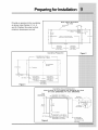
(MPORTANT
SAFETY(NSTRUCT(ONS
..............................................
m
[]
[]
m
[]
[]
[]
m
[]
[]
[]
m
[]
[]
[]
m
[]
[]
[]
m
[]
[]
))))))))))))))))))))))))))))))))))))))))))))))))))))))))))))_i!i
¸!!iiiiiiiiiiiiiiiiiiiiiiiiiiiiiiiiiiiiiiiiiiiiiiiiiiiiiiiiiiiiiiiiiiiiiiiiiiiiiiiiiiiiiiiiiiiiiiiiiiiiiiiiiiiiiiiiiiiiiiiiiiiii)
Safety Precautions
Do notattemptto
install oroperateyour
unit until you have readthesafety
precautions in this manual. Safety itemsthroughoutthis
manual are labeled with a
Warning or Caution based onthe risktype.
Definitions
_Thisisthesafetyalertsymbol.
iniuiyhazards.
injuryordeath.
Itisusedtoalertyoutopotentialpersonal
Obeyallsafetymessagesthatfollowthissymboltoavoid
possible
Safety 3
SAFETYPRECAUTIONS
[]
[]
[]
[]
[]
[]
[]
[]
[]
[]
[]
[]
[]
[]
[]
[]
[]
[]
[]
[]
[]
[]
,,%,
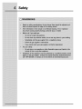
WARNING
•
Read all instructions
before using the appliance.
•
Improper installation, adjustment, alteration, service, or maintenance can cause
personal injury or property damage. Refer to these instructions and the
accompanying Use & Care Manual. For assistance or additional information,
consult a qualified installer, service agency, manufacturer (dealer), or the gas
supplier.
•
For your safety:
Do not obstruct the flow of combustion and ventilation air to the unit.
Keep appliance area clear and free from combustible material, gasoline and
other flammable vapors and liquids.
Do not use or attempt to use this appliance in the event of a power failure.
•
This unit is designed as a cooking appliance. Never use it for warming or heating
a room.
•
This appliance must be installed with the gas pressure regulator supplied with it.
•
Disconnect the electrical supply before installing or servicing the appliance.
•
This appliance must be grounded. Connect only to a properly grounded
electrical supply. Refer to "Electrical Requirements".
•
Install or locate this appliance only in accordance with these installation
instructions.
•
Use this appliance only for its intended use as described in this manual. Do not
use corrosive chemicals or vapors in this appliance. This type of appliance is not
designed for industrial or laboratory use.
•
As with any appliance, close supervision is necessary when used by children.
•
Do not operate this appliance if it has a damaged electrical cord, plug, conduit or
wires, if it is not working properly, or if it has been damaged or dropped.
•
This appliance should be installed and serviced only by qualified service
personnel.
•
Some products, such as whole eggs, and sealed containers, such as closed glass
jars, may explode and should not be heated on this cooktop.
Safety
Finding Information
READAND SAVETHESEINSTRUCTIONS
[]
[]
[]
[]
[]
[]
[]
[]
[]
[]
[]
[]
[]
[]
For toll-free telephone support in the U.S. and Canada:
1-877- 4ELECTROLUX
(1-877-435-3287)
For online support and Internet product
www.electroluxusa.com
information:
@2005 Eiectroiux Home Products, Inc.
Post Office Box 212378, Augusta, Georgia 30917, USA
All rights reserved. Printed in the USA
[]
[]
[]
[]
[]
[]
[]
[]
Finding Information
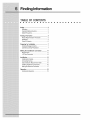
TABLEOF CONTENTS
Safety .....................................................................
2
Definitions...........................................................
2
ImportantSafetyInstructions
...............................
2
SafetyPrecautions ..............................................
3
Finding Information............................................
5
PleaseReadAndSaveThisGuide....................5
Questions?
..........................................................
5
TableOfContents...............................................
6
Preparing for Installation ...................................
7
VerifyingPackageContents................................
7
Cabinet/Counterop
Preparation..........................
7
Makingthe GaslElectricConnection ...............11
Requirements...................................................
11
L,P,GasConversion........................................
12
Installation ..........................................................
14
...........................................................................................................................
InstallingtheCooktop........................................
14
ConnectingtheGas ..........................................
14
Gasand ElectricRequirements
Table...............15
InstallingtheBurnerComponents.....................16
MakingtheElectricalConnection......................17
Operation............................................................
18
VerifyingtheOperation......................................
18
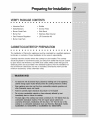
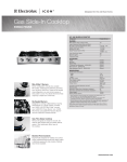
Preparingfor Installation
VERIFYPACKAGECONTENTS
[]
[]
[]
[]
• Literature
•
[]
[]
[]
[]
[]
[]
Pack
[]
[]
[]
[]
[]
[]
[]
[]
[]
[]
[]
[]
[]
[]
[]
[]
• Griddle
Bolts/Washers
• Simmer
Plate
• Burner Grate Pack
• Wok Stand
• Burner Set
• Stainless
• Gas Pressure
[]
Steel Cleaner
• LP Conversion
Regulator
Kit
• Burner Cap Pack
CABINET/COUNTER'FOP
PREPARATION
[]
[]
[]
[]
[]
[]
[]
[]
[]
[]
[]
[]
[]
[]
[]
[]
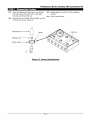
[]
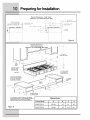
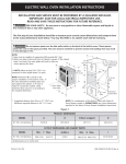
The installation of this built-in appliance must be completed by a qualified
technician or contractor. Proper installation is the owner's responsibility.
Carefully
check the location where the cooktop
is to be installed.
appliance
The cooktop
should be placed for convenient access, but away from drafts that may be caused
by open doors and windows or by HVAC duct outlets. Make certain that gas and
electrical power can be provided in the selected locations. Plan the installation so
that all minimum clearances are met or exceeded. Dimensions shown provide
minimum clearances,
unless otherwise noted.
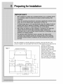
Preparing for Installation
Plan the installation so that the electrical
pressure
Figure 1
regulator
are accessible
E36GC76EPS: 36" (914mm) Minimum
E48GC76EPS: 48" (1219mm) Minimum
connection,
gas shut-off
stated
V
Minimum
30" {762turn)
......
5,8" (16turn) Overhar_g,
both sides
combustib]e side
wall both sides
/ _,2" (38ram)
Typical Cour_te_op
(457mm}
1
/8"
Q
®
J
H97mm)
7 3_4"
•
®
®
]
•
--
(g14mm)
/5 1_2rr
(393mm)
/254mm)
/0"
6
(see Figure
1). Locate
the electrical supply box
within reach of the included
Hood
Min to
valve, and
from the front of the cabinet and so that all of the
minimum required
dimensions are provided.
Dimensions apply to both
models unless otherwise
I
T
E48GC76EPS
30" (762mm)
28 /4"
(7/7mm)
J
48 inch long flexible cord so
the connection is accessible
when the cooktop
is in place.
Preparingfor Installation
Figure 3
++++++++++++++++++++++++++++++++++++++++++++++++++++++
Countertop
Cut-out
Dimensions
Cooktop is to be installed with Downdraft Vent
36" model: E36DD75ESS; 48" model: E48DD75SS)
(when
Hood
Vertical
non-combustible
surface
rear
wall
.,_
"_.
E36GC76EPS-33
_
E48GC76EPS
7/8"
- 43 1/2"
(860mm)
I_
(1105mm)
z _['_-.
_1
_
/
........ I
=
i21 3/8"
......
(543mm)
(716r_m)
I
i
I
I
Backsplash
i
I
Ii
Ii
/
/
Ii
|
Ii
Max.3/4"
(19ram)
_--_,
_[--]213/_+;
/'_
1_7_mm
1/4"
/
Min.
(6mm)
",,
_
_
flatledge
3" (76ram)
-5/8"
_
_E36
(16ram)
Figure 4
GC76EPS-34
E48GC76EPS-
'_-_
3/4'+ (883mm)/
46 3/4"
I
(1188mm)
E36GC76EPS
- 36"
(914rnm)
E48GC76EPS
- 48"
(1219mm)
--_
_
_._
6'+ (152mm)
Min.
to combustible
side
walls above the range
(both
sides)
iiiiiiiiiiii
t
T
I
i
,
i
"_
,,"
Preparing for Installation
Overall Dimensions
- Side Views
Clearance
to Combustible
Rear Wall
2½Ee4r_m]
OPTIONAL
STAINLESS
STEEL
BACKSPLASH
ACCBGO9
a6SI
Ea6GC76EPS:
ACCBD09
4SS_
E#SDC76EPS:
COMBUSTIBLE
REAR
FWALL
MATERIAL
TOP
OF
FINISHED
COUNTER_
743 E197mm]
Figure 5
Overall
Cutout
Clearance
Optional 9" stainless
steel backsplash
(attaches to wall)
to
Dimensions
Dimensions
_
............. _:_
Combusti
/
10" min. to nearest
combustible wall
(either side of unit)
Side inset s/8"
2 W' min. required distance
between rearedge of cooktop
and nearest combustible
surface above countertop.*
I,_3 Y2"
t/2" typical
countertop
edge
Suppo_
pla_orm
Openingto routegas /
and electricalsupply
* If 2 W' clearance can not be maintained, then optional
stainless steel backsplash or noncombustible backsplash
material must be used - otherwise this installation
will require custom cabinet and countertop dimensions.
Figure 6
Dimensions
Cooktop Model
A
B
C
D
E48GC76EPS
48" Min.
48"
46"
48"
E36GC76EPS
36" Min.
36"
34sA''
36"
Making the Gas/Electric Connection
[]
[]
[]
[]
[]
[]
[]
[]
[]
[]
[]
[]
[]
[]
[]
[]
[]
[]
[]
[]
[]
Gas SupplyRequirements
Check your local building codes for the proper method of installation. In the
absence of local codes, this appliance should be installed in accordance with the
National Fuel Gas Code ANSI Z223.1/NFPA 54. Be certain that the appliance being
installed is correct for the gas service being provided. Refer to the data plate
located on the bottom
of the cooktop
chassis.
[]
Making the Gas/ElectricConnection
LiQU(FIEDPETROLEUM(PROPANE)GAS CONVERS(ON
This appliance can be used with Natural Gas and Propane
the factory for use with natural gas.
Gas. It is shipped
from
A kit for converting to LP gas is supplied with your cooktop.
LP/PROPANE
GAS CONVERSION".
Follow the installation
The kit is marked "FOR
instructions which are
inside the envelope.
The conversion
must be performed by a
accordance
with the kit instructions and
Failure to follow instructions
could result
damage. The qualified agency performing
for the conversion.
qualified service technician
in
all local codes and requirements.
in serious injury or property
this work assumes responsibility
Making the Gas/Electric Connection
i
iiiiiiiiiiiiiiiiiiiiiiii
iiiiiiiiiiiiiiiiiiiiiiiiiiiiiiiiiiiiii
ElectricalSupplyRequirements
iiiiiiiiiiiiiiiiiiiiiiiiiiiiiiiiiiiiiiiii
iiiiiiiiiiiiiiiiiiiiiiiiiiiiiiiiiiiiiiiiiiiiiiiiiiiiiiiiiiiiiiiiiiiiiiiiiiiiiiiiiiiiiiiiiiiiiii
The correctvoltage,
frequencyand
amperage mustbe suppliedtothe
appliance
from an isolated, groundedcircuitwhich
isprotectedbyaproperlysizedcircuit
iiiiiiiiiiiiiiiiiiiiiiiiiiiiiiiiiiiiiiiiiiiiiiiiiiiiiiiiiiiiiiii
iiiiiiiiiiiiiiiiiiiiiiiiiiiiiiiiiiiiiiiiiiiiiiiiiiiiiiiiiiiiiiii
breakerortime-delayfuse,
iiiiiiiiiiiiiiiiiiiiiiiiiiiiiiiiiiiiiiiiiiiiiiiiiiiiiiiiiiiiiiii
HHHHHHHHHHHHHHHHHHHHHHHHHHHHHHHHHHHHHHHHHHHH
Thecooktopmustbeconnectedtothepowersupplywithcopperwireonly.
use of aluminum wire may result in unsatisfactoryconnections.
nonmetallic,
sheathedcoppercable(withagroundingwire)
The
Flexible armored
or
shouldbeusedto
supplyelectricalpowertothejunctionboxorreceptacle,
iiiiiiiiiiiiiiiiiiiiiiiiiiiiiiiiiiiiiiiiiiiiiiiiiiiiiiiiiiiiiiii
iiiiiiiiiiiiiiiiiiiiiiiiiiiiiiiiiiiiiiiiiiiiiiiiiiiiiiiiiiiiiiii
iiiiiiiiiiiiiiiiiiiiiiiiiiiiiiiiiiiiiiiiiiiiiiiiiiiiiiiiiiiiiiii
iiiiiiiiiiiiiiiiiiiiiiiiiiiiiiiiiiiiiiiiiiiiiiiiiiiiiiiiiiiiiiii
iiiiiiiiiiiiiiiiiiiiiiiiiiiiiiiiiiiiiiiiiiiiiiiiiiiiiiiiiiiiiiiiiiiiiii
The cooktop'sfactory-equipped,
matinggrounding-type
applicablestate,
receptacle
three-prong
grounding
inaccordancewith
plug mustbe
National
inserted into a
ElectricCodeand
municipalandlocalcodes,
iiiiiiiiiiiiiiiiiiiiiiiiiiiiiiiiiiiiiiiiiiiiiiiiiiiiiiiiiiiiiiii
iiiiiiiiiiiiiiiiiiiiiiiiiiiiiiiiiiiiiiiiiiiiiiiiiiiiiiiiiiiiiiii
iiiiiiiiiiiiiiiiiiiiiiiiiiiiiiiiiiiiiiiiiiiiiiiiiiiiiiiiiiiiiiii
iiiiiiiiiiiiiiiiiiiiiiiiiiiiiiiiiiiiiiiiiiiiiiiiiiiiiiiiiiiiiiiiiiiiiiiiiiiiiiiiiiiiiiiiiiiiiii
Becertaintolocatethejunctionboxorelectricaloutletsotheelectricalsupplymay
be easilydisconnected
inthe eventthatservice
becomes necessary.
extraslackinthecabletoallowthecooktoptoberemovedforservicing,
Also, provide
iiiiiiiiiiiiiiiiiiiiiiiiiiiiiiiiiiiiiiiiiiiiiiiiiiiiiiiiiiiiiiii
iiiiiiiiiiiiiiiiiiiiiiiiiiiiiiiiiiiiiiiiiiiiiiiiiiiiiiiiiiiiiiii
iiiiiiiiiiiiiiiiiiiiiiiiiiiiiiiiiiiiiiiiiiiiiiiiiiiiiiiiiiiiiiii
iiiiiiiiiiiiiiiiiiiiiiiiiiiiiiii
HHHHHHHHHHHHHHHHHHHHHHHHHHHHHHHHHHHHHHHHHHHH
Installation
INSTALLING
THECOOKTOP
m
[]
[]
m
[]
[]
[]
m
[]
[]
[]
m
[]
[]
[]
m
[]
[]
[]
m
[]
[]
[]
[]
[]
Place and center the cooktop within the cutout. Secure the cooktop to the
countertop utilizing the two (2) 1/4-20 bolts provided. Do not overtighten the
screws.
CONNECTING
THEGAS
m
m
[]
[]
[]
[]
Attach the gas pressure
inlet.
[]
[]
[]
regulator
[]
[]
(included
[]
[]
[]
[]
[]
with the cooktop)
[]
[]
to cooktop
[]
pipe nipple
Install a gas shut-off valve (not included with the cooktop) in the main gas supply
line in an accessible location near the cooktop.
Complete connection of the gas
supply to the cooktop by installing 1/2 inch flexible gas line (not included with the
cooktop) between the pressure regulator and the shut-off valve.
Installation
GAS AND ELECTR(CREQU(REMENTS
TABLE
[]
[]
[]
[]
[]
[]
Bll
[]
[]
[]
[]
[]
[]
[]
[]
Bll
[]
[]
[]
[]
[]
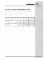
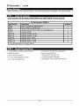
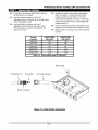
The required voltage, frequency and amperage ratings are listed on the product
data plate outside on the cooktop bottom. The gas and electric requirements
are
also shown in the table below.
((((((((((((((((((((((((((((((((((((((((((((((((((((((((((((((((,_
iiiiiiiiiiiiiiiiiiiiiiiiiiiiiiiiiiiiiiiiiiiiiiiiiiiiiiiiiiiiiiiiiiiiiii
_
Model No.
Electrical
circuit
required
Total
connected
load
Gas type
Manifold
pressure
Minimum gas
supply
pressure
Natural
4" Water Column
5" Water Column
Liquid Propane
10" Water Column
11" Water Column
Natural
4" Water Column
5" Water Column
Liquid Propane
10" Water Column
11" Water Column
E36GC76EPS
120VAC,
60Hz, 15A
0.7 Amps
(0.084 Kw)
E48GC76EPS
Installation
(NSTALUNGTHEBURNERCOMPONENTS
[]
[]
[]
[]
[]
[]
[]
[]
[]
[]
[]
[]
[]
[]
[]
[]
[]
[]
[]
[]
[]
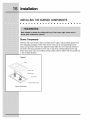
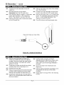
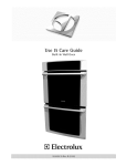
BurnerComponents
Remove the brass burner rings, porcelain burner caps, and porcelain grates from
their shipping packages. Place each burner ring onto its corresponding
burner
base, being certain that the four alignment tabs slide into the matching notches in
the base. Set each porcelain burner cap on top of its corresponding
burner ring.
Place each grate onto the cooktop, being certain that the rubber feet are positioned
in the locating dimples.
Figure 7
J
Grate
Burner Cap
J
Burner Ring
/Top Frame
........... Burner Head (Fixed)
Burner Components
[]
Installation
MAK(NGTHE ELECTR(CALCONNECT(ON
[]
[]
[]
[]
[]
[]
[]
[]
[]
[]
[]
Plug the three-prong plug from the appliance
polarized wall receptacle.
[]
[]
[]
[]
[]
into the properly
[]
[]
grounded
[]
[]
and
[]
[]
Operation
VER(FY(NG
THE OPERAT(ON
..............................................
m
m
[]
[]
[]
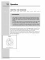
Before beginning
[]
[]
[]
[]
the test procedure,
[]
[]
[]
[]
[]
[]
[]
[]
[]
[]
ensure that the gas supply is turned
[]
[]
off at the
shut-off valve, all cooktop control valves are in the "OFF" position, and all burner
rings, burner caps, and grates are properly positioned on the cooktop.
Rotate one knob at a time counterclockwise
to the "LITE/Hr' position. Verify that all
ignitors spark continuously, then return the knob to the "OFF" position. Repeat for
all knobs. See Figure 8.
Figure 8
Burner
Control
Valve
[]
Operation
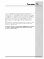
Turn on the main gas supply to the cooktop
by opening the gas shut-off valve. Test
each burner separately by pressing and turning one control knob at a time
counterclockwise
to the "LITE/Hr' position. All ignitors will spark simultaneously.
(It
will take approximately
four seconds for ignition to occur, at which time all igniters
will stop sparking. If ignition does not occur within four seconds, turn off the knob,
wait for at least five (5) minutes to allow any gas to dissipate, then repeat this
ignition test.) The control knob can then be rotated counterclockwise
from "HI" to
"LOW" to adjust the flame height progressively.
Repeat the ignition test for all
burners.
When installed properly, the flame will be steady
blue inner cone that will vary in length proportional
adjustment will not be necessary.
Read and understand the accompanying
this appliance. The Use & Care Manual
service and warranty information.
and quiet. It will also have a sharp,
to the burner size. Flame
Use & Care Manual prior to cooking
contains additional important safety,
with
iii
iiiiiiiiiiiiiiiiiiiiiiiiiiiiiiiiiiii
I
Professional
ICON
series
Liquid Petroleum Gas (LPG) Conversion
Instructions
Kit
Cooktop Models:
E36GC76EPS, E48GC76EPS
Model E36GC76EPS shown
----_ WARNING:
_
This conversion kit shall be installed by a qualified service agency in accordance
with the manufacturer's
instructions and all applicable codes and requirements
of
the authority having jurisdiction,
If the information
in these instructions is not
followed
exactly, a fire, explosion, or production of carbon monoxide may result
causing property damage, personal injury, or loss of life, The qualified service
agency is responsible for the proper installation of this kit, The installation is not
proper and complete until the operation of the converted appliance is checked as
specified in the manufacture's
instructions supplied with the kit,
CAUTION"
•
Before proceeding with the conversion, shut off the
gas supply to the appliance prior to disconnecting the
electrical power.
•
Do not reconnect electrical power until all leak tests
have been performed.
_
•
Only a qualified service technician
service this appliance.
should convert or
•
Be sure the unit is unplugged
proceeding with the conversion.
and coot before
IMPORTANT:
Read and save these instructions
for use by the building inspector.
for future use and
The cooktop will not operate properly unless the
regulator is converted according to these instructions.
The cooktop will not operate properly unless the
correct sized orifices and air shutters are installed for
each burner and valve and the air shutters for each
burner are properly adjusted.
After installing the LPG orifices, be sure to keep the
original factory installed orifices for future conversion
back to natural gas. See page 12 for instructions on
how to convert this appliance to natural gas from
LPG.
Part No. 100444 Rev. 3
[] Electrolux
I Ic o N
Before converting to LPG, install the cooktop in the cabinet according to the installation instructions provided.
LPG Conversion
Kit for Models
E36GC76EPS
and
Kit Part Number:
Part Number
E48GC76EPS
(36 and 48-Inch)
700208-1
65480
Description
LABEL, CONVERSION INFORMATION
86007
TOOL, REMOVAL, BURNER RING
100444
INSTALLATION INSTRUCTIONS r LPG CONVERSION KIT
76125*
92125-48
O-RING r BYPASS
ORIFICE, BYPASS, .48 MM
92125-61
ORIFICE, BYPASS, .61 MM
72427-86
ORIFICE r MAINr .86 MM
72427-112
ORIFICE r MAINr 1.12 MM
ORIFICE, MAIN, 1.18 MM
72427-118
quantity
2
1
1
6
2
4
2
2
2
* Provided assembled to the bypass orifices
I,."i | =I",_ ___ "-.,i+;..l
,_+ 1:._1<_,|_i i iL._,Ii [,_ F
• 1/8" flat blade and Phillips head screwdriver
° Thread-locker
• Needle-nose pliers
° 10 mm open end wrench
° Burner ring removal tool
(provided with conversion kit)
° 6" and 8" long adjustable wrenches
° U-tube manometer (calibrated)
° 6" (or 150 mm) pocket rule
° Leak detector: Gas or bubble forming fluid
Page 2
(Loctite 242 or equivalent)
Professional
3-1
If the cooktop is connected to a natural gas
supply line, close the gas supply valve.
3-2
Disconnect the cooktop power connector from
the electrical outlet.
Series Cooktop
LPG Conversion
3-3
Remove the grates from the top.
3-4
Remove all of the burner caps and burner rings
from top of the burner heads.
Remove grates-_
Burner cap
Burner ring-
Burner head--
Fiqure
3-1
Grate,
Burner
Kit
Cap, and Burner
Page 3
Rinq
Removal
[] Electrolux
[ mc o N
4-1
Locate the regulator. It is underneath the
cooktop, below the right rear burner.
4-2
Remove the regulator cap from the regulator.
Make sure that the regulator spring remains in
place.
4-3
Remove the spool from the cap and insert the
opposite side, The large end of the spool must
insert into the regulator first for LPG operation,
4-4
Replace the cap, inserting the end of the spool
into the center of the regulator spring,
Regulator spring
Spool: Direction
_
forLPG
_
Regulator cap
_
"_
\
Spool: Direction
for natural gas
Fiqure
4-1
Regulator Location
Requlator
Page 4
Conversion
Professional
5-1
Insert the large end of the burner ring removal
toot into the top of the left rear burner head.
Unscrew and remove the nut.
5-2
Remove the burner head, Slip the igniter wire off
of the burner as you remove it.
Removal toot
Retaining nut
Series Cooktop
5-3
Repeat steps 5-1 and 5-2 for the remaining
burners.
5-4
Lift out the spill tray.
Spill tray
Igniter
/
Burner head
Fiqure
5-1
LPG Conversion
Burner
Head
Page 5
Removal
Kit
[] Electrolux [ Ic o N
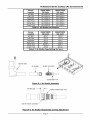
6-1
6-2
Make sure all knobs are in the off position,
Remove all of the burner knobs from the front of
the burner location, The bypass orifice's size is
stamped on its head,
the cooktop,
6-ai
6-4
6-5
bypass orifice from the right side of the valve
assembly,
Insert the bypass orifice and the attached o-ring
into the right side of the valve with the needle
nose pliers. Tighten into place with the fiat-blade
screwdriver.
6-6
Identify the appropriate bypass orifice from
Table 6-1. Match both the model number and
Repeat steps 6-1 through 6-5 for the remaining
burner valves,
6-7
Replace the knobs.
Insert the fiat-blade screwdriver into the valve
stem hole for the left rear burner, Unscrew the
Burner
E36GC76EPS
Location
Left Rear
{36-Inch)
61
E48GC76EPS
{48-Inch)
61
Left Front
48
48
Right Rear
48
61
61
61
61
Center Front
61
61
i
I
48
Right Front
Center Rear
Table 6-1
Bypass Orifice Sizes (x 100 mm)
Valve stem hole
J
__
Valve assembly
Bypass orifice
Fiqure
6-1
Bypass
Orifice
Page 6
Conversion
Professional
7-1
Remove the two screws that hold the left rear
burner base to the chassis.
7-2
Hold the shutter connector with the 8"
adjustable wrench. Remove the air shutter using
the 6" adjustable wrench.
7-5
Check to make sure that the compression nut is
tightened into the back of the shutter connector.
7-6
Repeat steps 7-1 through 7-5 for the remaining
burners.
Burner
E36GC76EPS
E48GC76EPS
Location
Left Rear
_36-Inch_
112
_48-Inch_
112
Left Front
86
86
Right Rear
86
86
Ricjht Front
Center Rear
112
118
112
118
Center Front
118
118
i
Main Orifice Sizes (X 100 mm)
Burner base
Compression nut
Main orifice
Air shutter (remove)
Shutter connector
Fiqure
7-1
Kit
orifice's size is stamped on its side, The shutter
and the burner base will be re-assembled after
pressure testing,
Hold the shutter connector with the 8"
adjustable wrench. Remove the main orifice
from the shutter connector using the 10 mm
open-end wrench.
Table 7-1
LPG Conversion
Replace the main orifice with the appropriate
size from Table 7-1, Match both the model
number and the burner location. The main
I
7-3
7-4
Series Cooktop
Main Orifice
Page 7
Conversion
[] Electrolux [ ic o N
I_'t
/ _ "Jl: -I
8-1
_:'_'1 D1 i iiI
_i i_-!-I
! I iC_II 1_-_ !-
Connect the U-tube manometer to the LPG
8-5
Make sure all knobs on the front of the cooktop
are in the off position.
supply line.
8-2
With electrical power to the cooktop
disconnected, open the LPG supply valve.
8-6
Connect the U-tube manometer to the left rear
burner's main orifice with 3/8" surgical tubing.
8-3
Verify that the pressure is above 11 inches water
column (WC) and below 1/2PSI. Consult the
factory if the pressure is not within the limits.
8-7
8-4
Close the LPG supply valve. Connect the cooktop
to the LPG supply line.
Open the LPG supply valve. Turn on the left rear
burner. The manometer should read 10 inches
WC +/- 1/2inch. Contact the factory if the
reading is not within the limits.
8-8
Turn off the burner and the gas supply valve.
Place end of tube over main orifice
7
Fiqure
9-1
8-1
Pressure
Determine the appropriate air shutter part
number for the left rear burner from Table 9-t
9-2
on page 9.
and burner
appears on
Thread the
9-3
connector about 6 turns (see Figure 9-1).
Reinstall the burner base.
9-6
Be sure to match the model number
location. The shutter part number
its side.
air shutter onto the left rear shutter
9-4
Measure the gap between the end of the shutter
connector and the opposite end of the shutter
opening with the pocket rule (see Figure 9-2).
9-5
Compare the measured gap to the gap listed in
Table 9-2 for the appropriate model number and
the burner location.
Test Set-up
Hold the shutter connector with the 8"
adjustable wrench. Adjust the air shutter using
the 6" adjustable wrench until the gap is to
within 1/16" (1.6 mm) of the gap indicated in
the table.
9-7
Secure the shutter with thread-locker
Figure 9-2).
9-8
Check to make sure that the compression nut is
still tightened into the back of the shutter
connector,
9-9
Repeat steps 9-I through 9-8 for the remaining
burners.
Page 8
(see
Professional
Series Cooktop
Burner
E36GC76EPS
E48GC76EPS
Location
Left Rear
_36-Inch_
HN A-0053-E
_48-Inch_
HN A-0053-E
Left Front
HN A-0052-E
HN A-0052-E
Right Rear
HN A-0052-E
HN A-0052-E
Right Front
Center Rear
HN A-0053-E
HN A-0053-E
HN A-0053-E
HN A-0053-E
Center Front
HN A-0053-E
HN A-0053-E
LPG Conversion
i
/
Table 9-1 Air Shutter
Burner
E36GC76EPS
E4BGC76EPS
Location
Left Rear
_36-Inch)
.38/9.7
_48-Inch)
.39/9.8
Left Front
.27/6.9
.12/3.1
Ric_ht Rear
.29/7.4
.18/4.7
Ric_ht Front
Center Rear
.39/9.9
.40/10.0
.38/9.6
.38/9.7
Center Front
.39/9.8
.40/10.1
Table
9-2
Air Shutter
Buiner base
Gaps Settings
(in/mm)
Shutter connector
Air shutter
_L_
Part Numbers
!
(
t
Compression nut
Fiqure
9-1
Air Shutter
Assembly
Shutter gap _
Apply thread-locker
here
I2-2
End of shutter connector"
Fiqure
9-2
Air Shutter
Reassembly
Page 9
and Gap Ad|ustment
Kit
[] Electrolux I Ic o N
10-1
Hake sure that all knobs on the front of the
10-4
cooktop are in the off position.
10-2
With electrical power to the cooktop
disconnected, open the LPG supply valve.
10-3
Using a gas leak detector or bubble forming leak
detection fluid, check the following for leaks:
• LPG gas supply connection
• All manifold connections
Re-assemble the burner heads, burner head
nuts, burner rings, and burner caps without the
spill tray in place. Be sure the igniter wire is
connected for each burner head.
10-5 Inspect all of the burner heads and verify that
the igniter for each head has not become
dislodged during re-assembly (see Figure 10-1
for the correct igniter orientation).
10-6 Connect the cooktop to the electrical outlet.
• All valve connections
10-7 Turn each burner on HIGH, one at a time.
Check for leaks around the valves (including the
bypass orifice) and the burner lines.
• Bypass orifices
Igniter
1
J
\
Burner head
/
Connect igniter wire here
Fiqure
10-1
Iqniter
Location
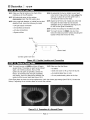
11-1 Turn each burner on HIGH and then off again,
several times. The igniter on each burner should
spark 2 to 5 times a second. If any of the
igniters do not spark as specified, contact the
factory. If the flame does not light repeatedly
and rapidly, check for obstructions between the
igniter and the burner head (see Figure 10-1).
and Connection
11-2 Make sure that the flame:
• Is stable.
• Does not waver or lift up from the burner.
• Is predominatety blue in color.
• Is not predominately yellow at the tips.
If the flame does not have the correct appearance, check the shutter gap settings (see STEP 9). Contact the
factory if adjusting the air shutters does not correct the problem.
Fiqure
11-1
Examples
of a Normal
Page 10
Flame
Professional
Series Cooktop
LPG Conversion
Kit
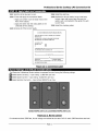
12-1 Wait for all the burners to coot.
12-4 Install the spill tray.
12-2 Fill out and apply the conversion labels:
12-5 Replace the burner heads, burner head nuts,
burner rings, and burner caps. Be sure the
igniter wire is connected to the igniter for each
burner head.
• Apply one where it can be easily read on the
floor of the chassis.
• Apply the other near the rating label on the
underside of the cooktop.
12-6 Install the cooktop grates.
12-3 Remove all of the burner heads.
CONVERSION
AFFIX THIS LABEL AS CLOSE
RATING
INFORMATION
AS POSSIBLE TO THE EXISING
PLATE.
FOR MODEL
NO., RATINGS
iNFORMATiON:
AND
SEE ORIGINAL
MANIFOLD
NAME
PRESSURE
PLATE,
GAS SUPPLY TYPE:
NATURAL GAS
[]
LP
[]
CONVERSION
KIT P/N.
THIS APPLIANCE
WAS CONVERTED ON
DAY/MONTH/YEAR
TO
GAS WITH KIT NO.
OF,
(INSTALLER)
WHICH
(COMPANY
NAME)
ACCEPTS THE RESPONSIBILITY THAT THIS CONVERSION
HAS BEEN PROPERLY MADE
Fiqure
I ;_lU
I itn[;1 il [I_'1_I l [__.1_.11To|z_ iili['r[i
12-1
Conversion
Label
_J[t[o] l 1.1[_[;] _| _[o] nT.
The ElectroIux Professional Series cooktop is equipped burners having the following ratings:
[]
Sealed power burner(s) - input rating: 17,000 BTU per hour.
[]
Sealed power burners - input rating: 15,000 BTU per hour.
[]
Sealed precision burner(s) - input rating: 8500 BTU per hour
E36GC76EPS
(36-Inch)
Fiqure
and E48GC76EPS
12-2
Burner
(48-Inch)
Layout
For elevations above 2000 feet, burner ratings are reduced at the rate of 4% for each 1000 feet above sea level.
Page 11
If it is necessary
to returnthe cooktopto naturalgasservice,repeatallofthe stepsin thisprocedure
usingthe
partsthat havebeenremoved.Usethe chartbelowto determine
the orificesizes,shuttergaps,andthe air
shutterpartnumbers.
Natural
Gas Conversion
Specifications
Burner
Bypass Orifice
Main Orifice
Air Shutter
Air Shutter
Location
Left Rear
_X 100 mm)
81
_X 100 mm)
184
Part No.
HN A-0053-E
Gap
.37/9.5
Left Front
72
135
HN A-0052-E
.09/2.3
Ric_htRear
72
135
HN A-0052-E
.09/2.3
Ricjht Front
Center Rear
81
81
184
194
HN A-0053-E
HN A-0053-E
.37 9.4
.37/9.5
Center Front
81
HN A-0053-E
.38/9.6
194
Model E36GC76EPS
(36-Inch)
Burner
Bypass Orifice
Main Orifice
Air Shutter
Air Shutter
Location
Left Rear
_X 100 ram)
81
_X 100 ram)
184
Part No.
HN A-0053-E
Gap
.38/9.6
Left Front
72
135
HN A-0052-E
.09/2.3
Right Rear
72
135
HN A-0052-E
.09/2.3
Ric_htFront
81
184
HN A-0053-E
.39/9.9
Center Rear
81
194
HN A-0053-E
.37/9.5
Center Front
81
HN A-0053-E
.38/9.7
194
Model E48GC76EPS
The Electrolux Group
USA • 250 Bobby Jones Expressway * Augusta, GA 30907
1-877-4electrolux
(1-877-453-8287)
• www.etectroluxusa.com
CANADA • 5855 Terry Fox Way • Mississauga,
1-800-888-4608
• www.electroluxca.corn
ON L5V 3E4
Page 12
(48-Inch)