1
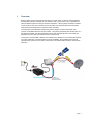
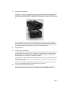
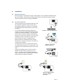
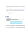
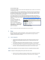
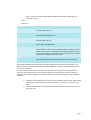
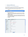
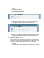
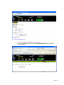
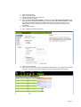
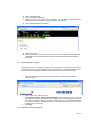
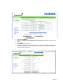
Automatic Link
Verification and
Restoral
iBoot BGAN Terminal Reboot
Version 1
05.11.2010
Automatic Link Verification and Restoral
iBoot BGAN Terminal Reboot
Contents
1 Overview
1 2 System Components
2 3 Key Features
2 3.1 Link Verification and Restoral
2 3.2 Local Terminal Verification and Restoral
2 3.3 Minimal Data Cost
3 3.4 Manual Control via Web & Telnet
3 3.5 Scheduled Power Control
3 4 5 6 Installation
4 4.1 Ethernet Connections
4 4.2 AC Power Connections
4 4.3 Mounting Options
5 4.4 Initial Configuration
5 Operation
5 5.1 5 8 6 Setup
6.1 7 Web Browser
Device Configuration
6 Configuring the BGAN terminal
8 7.1 Setting up BGAN – Thrane & Thrane EXPLORER 300/500/700
8 7.2 Setting up BGAN – Wideye™ Sabre™ I
9 7.3 Setting up BGAN – Hughes
12 Technical Specifications
14 8.1 Physical
14 8.2 Power
14 8.3 Compliance
14 8.4 Network
15 Automatic Link Verification and Restoral
iBoot BGAN Terminal Reboot
1
Overview
BGAN systems provide vital communication links for a wide variety of mission critical applications.
Knowing that the link is available when it is needed is vital to the success of any organization that
relies on BGAN systems for timely and accurate information. When systems are sited in unstaffed,
remote locations, the cost of downtime in lost information, and the time value of that information,
staff time and travel expenses for restoral becomes untenable.
The Automatic Link Verification and Restoral system is designed to insure that these critical
systems are available whenever they are needed. The system periodically tests the link status on a
pre-defined schedule, and with minimal data load and can automatically reboot the terminal and
peripheral devices if and when the link has been compromised.
The system is customizable to allow the user to balance the relative low cost of data traffic required
for system verification, with the timeliness of system availability. Both satellite facing and local
network facing systems can be tested to insure that no recoverable failure results in critical system
downtime.
Page 1
2
System Components
The system consists of an application optimized version of Dataprobe’s iBoot-G2 Network Enabled
Power Switch. The iBoot is designed for automatic and user control of A/C power via network
protocols (Web, Telnet, ICMP etc.). It is designed for worldwide power mains 100 – 240 VAC 50/60
Hz.
The standard iBoot-G2 has been optimized for BGAN terminal verification. These modifications
allow a minimum of data traffic to be used for link verification and allow scheduling of verification
tests to a wider range of time parameters. These changes are designed to minimize the data costs
of link verification while still providing timely reboot for restoral when required.
3
Key Features
3.1
Link Verification and Restoral
The iBoot uses ICMP ‘ping’ tests for link verification. Two IP addresses can be tested, each with its
own parameters as to frequency of tests. Typically one IP address would be across the satellite
link and another to the local terminal. Ping testing is the ideal way to provide link verification for
satellite systems, as it only requires 74 bytes in each direction.
Ping parameters set both the frequency of the pings from 1 second to 999 hours and the number of
tests to perform during each cycle. Any one valid response verifies the link availability to minimize
data traffic on good links.
Should the local or remote link be determined unavailable, the iBoot will power cycle the terminal,
wait for a user selectable time then re-test the system to insure rest oral.
3.2
Local Terminal Verification and Restoral
The second Ping test can be pointed to the local terminal for service availability. The frequency of
this test can be much higher, as there are no data charges associated with this connection.
Page 2
3.3
Minimal Data Cost
The minimal data cost of the system means that link verification testing is a low cost means to
insure high availability.
The system requires 74 bytes in each direction to validate connectivity with the target IP address.
Below is a network capture of a typical set of four ping verifications.
The following chart provides some examples of total data cost for various testing frequency.
Per Day
Per Month
Per Year
Every Hour
3552 Bytes
105.5 KB
1266 KB
Every 6 Hours
592 Bytes
17.6 KB
210 KB
Every 12 Hours
296 Bytes
8.8 KB
105.5 KB
Every 24 Hours
148 Bytes
4.4 KB
52.8 KB
Based on 74 bytes in each direction per ping.
3.4
Manual Control via Web & Telnet
In addition to the automatic link verification, the iBoot has an internal Web Server and Telnet
Server. By pointing a web browser or telnet client to the IP address of the iBoot, the administrator
can manually power control the unit, and manage the device.
3.5
Scheduled Power Control
The system can also use a real time clock (internal or NTP Server set) to provide scheduled power
control. Examples in this application could be:
•
Keep unused systems powered down until needed. In SCADA or other telemetry applications,
reporting may be done on a periodic basis. In this case, the system can be powered down to
conserve energy or minimize heat gain and powered up only when needed
•
Reboot on a scheduled basis. For system with known issues, it may be advisable to reboot once
a day, perhaps just prior to a daily transmission to insure terminal availability at the critical time.
Up to 8 schedules can be set with varying frequencies
Page 3
4
Installation
4.1
Ethernet Connections
iBoot-G2 supports 10/100 Ethernet using the cable supplied, or other suitable unshielded twisted
pair (Cat 5) cabling. Link (amber) and Activity (green) LEDs on the network connector indicate
when the network connection is properly established.
4.2
AC Power Connections
Connect the device to be powered ON and OFF to the
IEC receptacle marked A/C Output. An IEC 320 to
North American (NEMA 5-15) power cord is included
for connecting the iBoot-G2 outlet to the device to be
controlled.
If a cord with a different terminating receptacle is
required, be sure it is properly rated and meets all the
required local electrical standards. If the device to be
powered uses an IEC320 receptacle and detachable
power cord, an IEC to IEC extension cord can be used.
Connect 10/100 Ethernet
The iBoot-G2 can be connected to a power strip to
allow simultaneous control of multiple devices.
Make sure that the combined load of all controlled
devices does not exceed 12 Amps for 105-125VAC or
10 Amps for 210-240VAC.
An LED Indicator next to the Switched Outlet will be
On to indicate that the power is On at that outlet. This
LED will turn Off to indicate that the power is Off to the
outlet.
Outlet Cord for
North America
Connect the supplied power cord to the connector
labelled A/C Input, and the other end to your AC
source. If a power cord with a different terminating
plug is required, be sure it is properly rated and meets
all the required local electrical standards.
Source Additional
Outlet Cables
Locally
Page 4
4.3
Mounting Options
iBoot-G2+ is suitable for desktop or shelf mounting. A mounting kit for wall and DIN rail mounting is
also available.
4.4
Initial Configuration
The Device Management Utility (DMU), available online at http://dataprobe.com/support/iboot.html,
provides the easiest means to find and configure your iBoot-G2 for use. It can discover all the
iBoots on your network, display the current IP address of each, and allow setting of any valid IP
address.
Other ways to set the IP Address
1.
1.
1.
Automatically from a DHCP Server
Web Browser via the Set-up Page
CLI (Telnet & USB)
iBoot-G2 comes with factory installed IP address 192.168.1.254.
5
Operation
5.1
Web Browser
Password Protection
iBoot-G2 uses two username/password credential sets, one for normal power control (User) and
one that also provides access to the setup functions (Admin).
Default Credentials:
Role
Username (fixed)
Password (user set)
Administrator
admin
admin
User
user
user
Open your browser and enter the IP address of iBoot-G2 into the address bar. If you have changed
the IP address by any of the methods described, enter that address, otherwise, use the default IP
address 192.168.1.254
Enter the username and password as prompted. When the proper username/password is received
the Control and Status Page is displayed.
Page 5
Control and Status Page
Once the user is validated, the Control and Status is displayed. (Only one person can be connected
to the iBoot-G2 at a time.)
To control the power, click on the appropriate button. During power cycling, the Power Status bar
will indicate the temporary status, with a blue background. Once the cycle is complete, the status
bar will revert to its original condition. To abort a power cycle, click on either Power On or Power
Off buttons. iBoot-G2 will assume the status selected.
If the AutoPing features is in use, the page will also display the current status, OK or Failed, for
each AutoPing used, with a counter of how many times it failed and how many times the Action was
triggered. If connecting with the Admin credentials, reset buttons for the Fail and Trigger counters
are provided.
To access the Setup page, the
administrator credentials must be
used for the initial login.
When you are finished with iBoot,
click on Logout. A confirmation page
will be displayed. If another user is
logged into the iBoot-G2, an In Use
page will be displayed.
Device Setup Page
Note: For command line and DxP Protocol please refer to the user manual
6
Setup
iBoot-G2 setup section consists of several pages. Access any page via the buttons on the left of
the page. Each time a setting is changed click on the Save button for that page to save the
changes before moving to the next page.
6.1
Device Configuration
1. Under the Device settings option set a device name and set the cycle time. This is the
length of time the power will be off during a reboot, or on during a power burst. Save
changes.
2. Under Network settings enter IP address information accordingly. You can also change
from standard port settings for HTTP, telnet and set auto log off here. Save changes.
3. The AutoPing feature will ping a periodically. Enter the details for addresses, frequency and
scalar here. Fail counter will determine how many fails are occurred before a cycle.
NOTE: Pinging addresses over the air interface will result in chargeable data being created.
NOTE: Changes to AutoPing settings will only take effect with a reboot.
4. Next set the mode of operation accordingly to the table on the next page. Select from AND,
OR or Single. With And, both AutoPings need to exceed their fail count to trigger the
Page 6
Action. With Or, the Action will be triggered if either AutoPing fails. With Single, only
AutoPing 1 is used.
Action:
Select from
None
AutoPing not used
Power On – Latch
Upon triggering, iBoot-G2 will power on and remain so until changed via
the web, telnet, DxP, etc.
Power On – Follow
Upon triggering, iBoot-G2 will power on. When the ping response
returns, iBoot-G2 will power off.
Power Off – Latch
Upon triggering, iBoot-G2 will power off and remain so until changed via
the web, telnet, DxP, etc.
Power Off – Follow
Upon triggering, iBoot-G2 will power off. When the ping response
returns, iBoot-G2 will power on.
Power Cycle
Upon triggering, iBoot-G2 will cycle the power. iBoot-G2 will wait the
Ping Frequency x Fail Count; if the response does not return, the power
will be recycled again. This will continue until the ping response returns
or Auto Ping is turned off. Make sure your Auto Ping frequency is longer
than the time required to reboot your device.
Power Cycle Once
Upon triggering, iBoot-G2 will cycle power one time. It will not cycle
again automatically until the ping response returns and is lost again.
With AutoPing operational, the main iBoot-G2 page will display the current status of this feature. The
status will be OK to indicate that iBoot-G2 is receiving responses to the ping, or that the fail counter has
not yet been exceeded.
If the fail count has been exceeded, the status will change to FAIL. The Fail Counter will indicate the
number of times the failure has occurred, and the Trigger Counter indicates the number of times the
AutoPing action has been triggered. A counter reset button is provided when logging in with the Admin
password.
5. Under the event scheduling menu you can set up to 8 different power events. Set the initial
date and time, repeat cycle and the action to be taken. i.e. power on, off or power cycle.
Save.
6. It is recommended that you setup passwords under the password screen for access to the
IBoot unit. Save.
Page 7
7
Configuring the BGAN terminal
7.1
Setting up BGAN – Thrane & Thrane EXPLORER 300/500/700
The terminal needs to be configured to switch on when external power is connected; no Pointing is
required at power up and to automatically activate a data connection. The BGAN terminal and can be
configured from the EXPLORER™’s built-in web server (via a laptop’s web browser)
1.
Open your internet web browser and type the following IP address in the address bar:
192.168.0.1
2.
3.
Click on Settings and then LAN
Now you should see the web server interface. The screenshot below shows the settings
required as configured via the EXPLORER™’s web server interface, ensure you click apply
before leave the web page. Please consult your EXPLORER™ manual for more detailed
information.
NAT Mode Select Router
APN Select User Defined, enter the APN, user name and password provided by your SP in
order to get a Static IP address. NOTE: If no static IP address is used your IP address will
change every time you connect to the BGAN network. On the dashboard screen you can see
the IP address of you connection.
Automatic Activation select Enable.
Click Apply
4.
5.
6.
7.
Page 8
8.
Now your terminal is configured to start a Standard connection after you register on the
network.
9. Click on Setting on the left Menu.
10. Select the NO radio button for Pointing required at power up.
11. Select the YES radio button for the terminal will switch on when external power is connected.
12. Click APPLY before leaving the page.
13. Click on LAN from the menu on the Left.
14. Click on Port Forwarding select ENABLE.
15. Check the Active box and enter 80 for the Incoming port Range and the IP address you
configured in your iBoot-G2 ex. 192.168.0.X then for the destination port 80
16. Your configuration should look like this:
17. Click APPLY before leaving the page.
18. Restart your terminal, after properly pointing the terminal. The Explorer terminal will register
automatically on the BGAN network you will be connected automatically with a Standard
connection.
7.2
Setting up BGAN – Wideye™ Sabre™ I
The terminal needs to be configured to switch on when external power is connected; no Pointing is
required at power up and to automatically activate a data connection. The BGAN terminal and can
be configured from the Wideye™ Sabre I’s built-in web server (via a PC’s web browser).
2.
3.
Open your internet web browser and type the following IP address in the address bar:
192.168.1.35
Then you will prompt for the User Name: Admin Password: wideye. Now you should see
the screen below.
Page 9
4.
5.
Click on Auto Network registration upon power on
Select the AUTO radio button, and then click UPDATE SETTINGS. Your configuration
should look like this.
Page 10
6.
7.
8.
9.
10.
Click on the Data Icon
Click on Primary Profiles
Select the connection Type as Standard
Check mark ‘Set as default’
APN: APN Select User Defined APN, enter the APN, check Apply user defined APN, enter
the user name and password provided by your SP in order to get a Static IP address. NOTE:
If no static IP address is used your IP address will change every time you connect to the
BGAN network. On the Data Screen Connection Tab you can see the IP address of you
connection.
11. Click ‘Update Settings’
12. Your configuration should look like this
13. Click on Port Forwarding
14. Click Add, Enter the Incoming port 80 destination address the IP you assigned to the PNSC
192.168.1.X, Protocol TCP and the destination port 80. Check Enable and click Apply.
Page 11
15. Click on the Settings Tab
16. Select ‘Router Mode (Multi User)’
17. Check the box for ‘Auto PDP context Activation’. This will make the terminal start the
Standard connection automatically after you register on the network.
18. Your configuration should look like this
19. Reboot the terminal
20. Restart your terminal, after properly pointing the terminal. The Explorer terminal will register
automatically on the BGAN network you will be connected automatically with a Standard
connection.
7.3
Setting up BGAN – Hughes
The terminal needs to be configured to switch on when external power is connected; no Pointing is
required at power up and to automatically activate a data connection. The BGAN terminal and can
be configured from the Hughes™ HNS9201’s built-in web server (via a PC’s web browser).
1.
Open your internet web browser and type the following IP address in the address bar:
192.168.128.100
2.
3.
Click on ACA on the menu on the left.
Select ACA settings for TEs with Static IP address ‘ON’ for the range of 200 – 209. QoS
select Background. Enter the APN, user name and password provided by your SP in order to
get a Static IP address. NOTE: If no static IP address is used your IP address will change
every time you connect to the BGAN network. On the PDP Contexts screen you can see the
IP address of you connection
Click Apply
4.
Your configuration should look like this
Page 12
5.
6.
7.
8.
9.
Now click on SETUP.
Make sure Bypass Antenna Pointing and Auto Power On radio buttons are set to
ON.
Click Apply
Then Click Restart Terminal
Restart your terminal, after properly pointing the terminal. The Explorer terminal will
register automatically on the BGAN network you will be connected automatically
with a Standard connection.
Page 13
8
Technical Specifications
8.1
Physical
8.2
8.3
Height
2.0” 60mm
Width
3.2” 82mm
Depth
4.2” 107mm
Weight
8.6 oz 244g
MTBF
360,000 hours
Temperature
0 – 50 degrees C
Power
Input
IEC 320 C14
Input Cord
16AWGX3C 10A 250 UL/CSA/VDE Rated (1.25mm2X3C)
Voltage Range
Auto Sensing 105-240 VAC
Switched Receptacle
IEC 320 C13
Capacity
12 A Max at 105-125 VAC, 10 A Max at 210-240 VAC
Compliance
UL/cUL
UL60950 Listed I.T.E
File No. E225914
CE
Directives 89/336/EEC, 92/31/EEC and 93/68/EEC
EN 60950: 3rd Edition
EN 55022: 1998 Class B
FCC
Part 15 Class B
Page 14
8.4
Network
Dual 10/100 Unshielded Twisted Pair Ethernet Jacks.
IP Addressed, DHCP assigned or Static
Internal HTTP Web Server
Forms Processing Browser required
Telnet Server
Page 15