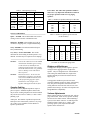
1
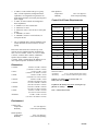
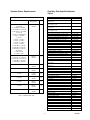
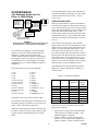
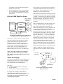
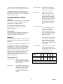
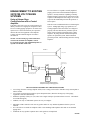
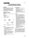
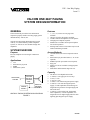
VSP – One-Way Paging
Issue 13
VALCOM ONE-WAY PAGING
SYSTEM DESIGN/INFORMATION
Features
GENERAL
•
These instructions provide the basic information
required to properly install a One-Way paging system
manufactured by Valcom, Inc.
•
•
•
•
Valcom One-Way Paging Equipment may be used
with any 1A2, Electronic Key, PABX Telephone
Systems, or with one or more dedicated single line
telephones.
•
SYSTEM OVERVIEW
Access Methods
Purpose
•
Provides telephone accessed single or multizone
paging.
•
Applications
•
•
•
•
1, 3, 6, 9, 19, 20 and 36 zone page units
available.
One-way all call to all speakers available.
Volume controls and amplifiers in each speaker.
No high power amplifier required.
Standard 22 or 24 AWG twisted pair telephone
wire used for speakers.
Existing house cables or feed cables may be used
without introducing crosstalk.
•
•
•
1A2
Electronic Key Systems
PABX
Stand alone systems
•
1A2 line button (line card not required on most
units).
Electronic Key System line button (C. O. circuit
required).
PABX loop trunk port (trunk circuit required).
Page port.
Station level access available (with appropriate
adapter).
Stand alone with dedicated single line sets.
Capacity
TELEPHONE
SYSTEM
•
•
•
•
•
•
VALCOM
ONE-WAY
CONTROL
UNIT
POWER
SUPPLY
ONE-WAY
SPEAKER
ASSEMBLY
•
ONE-WAY PAGING SYSTEM BLOCK DIAGRAM
FIGURE 1
1
All units are one talkpath and one link.
V-1094A, 1 zone (page port access only).
V-9937, 1 zone.
V-1101A, 1 zone.
V-2000, 1 zone with an integrated power supply.
V-2001A, 1 zone with an integrated power
supply, override capabilities and featuring two
integrated tone generators for night ringing and
time clock tones.
V-2003A, 3 zones with all call, background
music capabilities, override capabilities, two
integrated tones for night ringing and time clock
signaling plus integrated power supply.
947100
•
•
•
•
•
•
•
*
Horn Speakers:
Temperature
Humidity
V-2006A, 6 zones with all call, up to 3 group
calls, override capabilities, background music
capabilities, two integrated tone generators for
night ringing and time clock tones plus integrated
power supply.
V-2920*, 20 zones with all call, background
music capabilities.
V-1109RTVA, 9 zones with all call.
V-119RTVA, 19 zones.
V-119RTVA, with V-1118 all call, 18 zones plus
all call.
V-136RTHF*, 36 zones.
V-136RTHF*, with V-1134 all call unit, 34
zones plus all call.
Control Unit Power Requirements
Table 1
The V-136RTHF and V-2920 are handsfree page
control units that can also be used for one-way
paging.
Each of the units listed above will drive up to 40
Valcom one-way amplified speaker assemblies per
zone (150 on V-1094A, V-9937, V-1101A, V-2000,
V-2001A, V-2003A and V-2006A). Additional
speakers may be added to a zone by using a
V-1094A. Each V-1094A allows the addition of 150
more amplified speaker assemblies to that zone.
Dimensions
V-1094A:
V-9937:
V-2000:
V-2001A:
V-2003A:
V-2006A:
V-2920:
All Others:
-20 to +55 degrees C
0-95% non-precipitating
4.44"H x 2.75"W x 2.88"D
(11.28cm x 6.99cm x 7.32cm)
7.1"H x 4.7"W x 2.1"D
(18.03cm x 11.94cm x 5.33cm)
7.75"H x 5.8"W x 2.6"D
(19.69cm x 14.73cm x 6.6cm)
7.09"H x 9.0"W x 2.4"D
(18.0cm x 22.86cm x 6.1cm)
7.13"H x 10.00"W x 3.00"D
(18.1cm x 25.4cm x 7.62cm)
10.9"H x 13.00"W x 2.69"D
(27.7cm x 33.0cm x 6.83cm)
8.56"H x 11.0"W x 2.35"D
(21.7cm x 27.9cm x 6.0cm)
7.13"H x 5.9"W x 2.13"D
(18.11cm x 14.99cm x 5.41cm)
Control Unit
"A" Battery
(milliamps)
"B" Battery
(milliamps)
VPU
V-1094A
-
50
-1
V-9937
-
200
-4
V-1101A
50
100
-3
V-2000
Supplies 600 milliamps
+12
V-2001A
Supplies 1000 milliamps
+20
V-2003A
Supplies 1000 milliamps
+20
V-2006A
Supplies 1500 milliamps
+30
V-2920
A. C. Line Powered
0
V-1109RTVA
60
250
-6
V-119RTVA
60
250
-6
V-119RTVA/
V-1118
60
750
-16
V-136RTHF
90
500
-12
V-136RTHF/
V-1134
90
1500
-32
Notes for Table 1:
"A" Battery:
"B" Battery:
-21.5 to -26VDC filtered "talk" battery
-21.5 to -25VDC unfiltered "signal" battery
Filtered "A" battery may be used as both "A"
battery and "B" battery.
Unfiltered "B" battery may not be used in place of
filtered "A" battery.
VPU = Valcom Power Unit.
Environment
Control Units:
Temperature
Humidity
0 to +40 degrees C
0-85% non-precipitating
Inside Speakers:
Temperature
Humidity
-20 to +55 degrees C
0-95% non-Precipitating
2
947100
Speaker Power Requirements
One-Way Self-Amplified Speaker
Styles
Table 3
4" Ceiling Speaker
4" Recessed Ceiling Speaker (with backbox &
support rails)
4" Recessed Ceiling Speaker (with mounting
ring & support rails)
8" Recessed Ceiling Speaker (with backbox &
support rails)
8" Recessed Ceiling Speaker (with mounting
ring & support rails)
Black Track Style Speaker (1 watt version)
White Track Style Speaker (1 watt version)
Gray Track Style Speaker (1 watt version)
Black Track Style Speaker (5 watt version)
White Track Style Speaker (5 watt version)
Gray Track Style Speaker (5 watt version)
Black Pendant Speaker
White Pendant Speaker
Gray Pendant Speaker
Wall Speaker (black vinyl cover)
Wall Speaker (white vinyl cover)
8" Ceiling Speaker
8" Ceiling Speaker with knob
8" Ceiling Speaker with plastic grille
Wall Speaker (lt. brown open weave grille)
Wall Speaker (dark brown cloth grille)
Table 2
Speaker
Power
Requirements
VPU
V-1010C, V-1011BB,
V-1011MR,
V-1012BB, V-1012MR,
V-1013A-BK, V-1013A-W,
V-1013A-GY V-1016-BK,
V-1016-W
V-1020C, V-1020KNOB,
V-760C, V-763-BK,
V-763-W
V-1021C, V-1022C,
V-1023C, V-1024C,
V-1025C, V-1026C,
V-1027C, V-1028C,
V-1042-BK, V-1042-W,
V-1042-BR, V-1042-GY,
V-1080-BG, V-1080-GY,
V-1080-W,
V-1220, V-1222,
V-1224, V-1226
45 ma,
-24VDC
-1
V-1014A-BK, V-1014A-W,
V-1014-GY, V-1015A-W,
V-1015A-BK, V-1015A-GY,
V-1440-BK, V-1440-W,
V-1440-BR, V-1440-GY
300 ma,
-24VDC
-6
V-1030C/V-1030M
300 ma,
-24VDC
-6
V-1036C/V-1036M
900 ma,
-24VDC
-18
V-1038
1 Amp,
-48VDC
N/A
V-1039A
1 Amp,
-24VDC
-20
V-1050C
300 ma,
-24VDC
-6
V-1420
200 ma,
-24VDC
-4
V-1450
200 ma,
-24VDC
-4
Corner Speaker (lt. brown open weave grille)
Corner Speaker (dark brown cloth grille)
Bi-directional Corridor Speaker (lt. brown open
weave grille)
Bi-directional Corridor Speaker (dark brown
cloth grille)
Chandelier Speaker
Black Slimline Amplified Wall Speaker
White Slimline Amplified Wall Speaker
Brown Slimline Amplified Wall Speaker
Gray Slimline Amplified Wall Speaker
Desk Top Speaker
Black Desk Top Speaker
White Desk Top Speaker
5 Watt Horn
5 Watt Marine Horn
15 Watt Horn
15 Watt Marine Horn
30 Watt Horn
7 Watt Explosion-Proof Horn
5 Watt Bi-directional Horn
Beige Flex Horn
Gray Flex Horn
White Flex Horn
8" Dual Input Ceiling Speaker
Dual Input Wall Speaker
Dual Input Corner Speaker
Dual Input Bi-directional Corridor Speaker
Signature Series Ceiling Speaker
Black Signature Series Monitor Speaker
White Signature Series Monitor Speaker
Brown Signature Series Monitor Speaker
Gray Signature Series Monitor Speaker
Signature Series In-Wall Speaker
VPU - Valcom Power Unit
3
V-1010C
V-1011BB
V-1011MR
V-1012BB
V-1012MR
V-1013A-BK
V-1013A-W
V-1013A-GY
V-1014A-BK
V-1014A-W
V-1014A-GY
V-1015A-BK
V-1015A-W
V-1015A-GY
V-1016-BK
V-1016-W
V-1020C
V-1020KNOB
V-1021C
V-1022C
V-1023C
V-1024C
V-1025C
V-1026C
V-1027C
V-1028C
V-1042-BK
V-1042-W
V-1042-BR
V-1042-GY
V-760C
V-763-BK
V-763-W
V-1030C
V-1030M
V-1036C
V-1036M
V-1038
V-1039A
V-1050C
V-1080-BG
V-1080-GY
V-1080-W
V-1220
V-1222
V-1224
V-1226
V-1420
V-1440-BK
V-1440-W
V-1440-BR
V-1440-GY
V-1450
947100
The remaining number of power units required will
determine the quantity and model(s) of power supply
required. Reference the next section, "Valcom
Power Units".
SYSTEM DESIGN
1A2, Dedicated Single Line Set,
E-Key, or PABX Paging
Telephone T
System C.O.
Loop Start
R
Trunk Port
Valcom
Page
Control
Unit
- and/or -
Additional
Zones
(multi-zone
units only)
Valcom Power Units
Each page control/interface, speaker and peripheral
device has been assigned a Valcom power unit (VPU)
value. Products that provide power, such as the 2000
Series page control/interfaces or power supplies, have
power unit values indicated with a plus (+) sign.
Products that consume power have power unit values
indicated with a minus (-) sign. Products that neither
require nor provide power are indicated by a VPU of
zero (0).
Speakers
Power Supply
(if required)
One or more dedicated
single line telephone(s)
DIAGRAM 1
Block Diagram or Loop Start Trunk Port and/or Single Line
Telephone Access of a Valcom Page Control/Interface
After you have chosen the page control interface,
speakers and accessories for your application, simply
add up all of the Valcom power units [indicated by a
minus (-)] for each item that requires power. This
total tells you how much power you need. If you
have chosen a 2000 Series control/interface, subtract
the total power units provided by this controller from
your previous total. If you come out even, or you
have power left over, you paging system is complete.
However, if you come out with more VPUs required
than provided, you will need additional power.
To provide one-way paging on 1A2, E-Key PABX
Systems, or from one or more dedicated single line
telephones, you will need a page control unit,
one-way amplified speaker assemblies, and possible a
power supply. In most cases, page access will be via
a line button for 1A2, a loop trunk port for a PABX
or Electronic Key or via Tip and Ring on a singe line
telephone(s).
The additional power required will be provided by
adding one or more VALCOM power supplies as
listed in Table 4.
The control units may be any of the following.
1 zone
1 zone
1 zone
1 zone
3 zones w/all call
6 zones w/all call
9 zones w/all call
19 zones
18 zones w/all call
20 zones w/all call
36 zones
34 zones w/all call
V-1101A
V-9937
V-2000
V-2001A
V-2003A
V-2006A
V-1109RTVA
V-119RTVA
V-119RTVA/V-1118
V-2920
V-136RTHF
V-136RTHF/V-1134
Table 4 - Valcom Power Supplies
The speakers may be any of those listed in Table 3.
After you have selected the page control/interface and
the quantity and type of speakers for your system, use
Tables 1 and 2 to determine system power.
Part #
Voltage
Maximum
Current
VP-324
VP-624B
VP-1024
VP-2124
VP-4024C
VP-2048C
VP-412
VP-6124
-24VDC
-24VDC
-24VDC
-24VDC
-24VDC
-48VDC
-24VDC
-24VDC
250 ma.
600 ma.
1.0 amp
2.0 amp
4.0 amp
2.0 amp
4.0 amp
6.0 amp
Valcom
Power
Units
+6
+12
+20
+40
+80
N/A
+80
+120
There are several cases when more than one power
supply will be required:
Add up the total Valcom power units (VPU) that will
be required. Subtract any power units being provided
by page controls featuring integrated power (2000
Series).
1.
2.
4
When the power required exceed the maximum
output of the power supplies available: Add
additional supplies as required.
In large systems or systems with many horn
speakers: Locate separate power supplies near
groups of speakers. (Refer to Tables 8 and 10
947100
3.
The V-9940 is FCC registered for direct connection
to the public telephone network, and also carries U.L.
1459 approval. It will ring trip from 75 to 105
VRMS (20 to 30 hertz) ringing voltage.
for guidelines concerning maximum allowable
distances for power runs.
When the paging system is in several buildings
or on several floors of a single building, locate
power supply in each building or on each floor
being paged.
E-Key or PABX Page Port Access
Valcom One-Way
Amplified Speaker
Assemblies
Page Zone 1
Page Zone 2
Page Zone X
In V-1094A
V-2000
V-2001A
V-1094A
In V-2000
V-2001A
Out
With a single line telephone, the called party provides
the disconnect at the end of the conversation by going
"on hook". A station level page adapter, on the other
hand, has no way of "knowing" when the calling party
has finished speaking. This unit has to sense line
conditions in order to determine when it is time to
disconnect.
This line condition may be quiet line sensing, a strict
"time out" (disconnects after a selected period of
time) or open loop disconnect of at least 150
milliseconds. Open loop is a service provided by the
central telephone office and involves actually
disconnecting the telephone line from the C. O. for a
brief instant. In some cases the "quiet line" may also
be programmed via the PABX. "Quiet line" implies
that the PABX will not return any tones (dial tone,
busy tone, reorder tone . . . etc.) to the called station
at the completion of the station to station call. The
telephone system may be tested for a "no returned
tones" status with your test set; have someone call
you on a station and then ask them to hang up . . . if
you do not hear any tones, or if there is a delay of at
least 10 seconds before you hear any tones, then the
"quiet line" (i.e. audio sense time-out) may be used.
Out
Power Supply
DIAGRAM 2
Block Diagram of Multiple Zones of One-Way Paging
From Multiple Telephone System Page Ports
The Valcom V-1094A, V-2000 or V-2001A control
units may be used for page port access to Valcom
paging. Each of these units provide one zone of
one-way paging. If more than one page port is
available a V-1094A, V-2000 or V-2001A may be
used on each port for multizone paging. Refer to
Tables 2 and 3. For help in speaker and power
supply selection refer to the section titled "1A2,
Dedicated Single Line Set, E-Key, or PABX Paging" .
Ground start telephone lines are a good choice for use
with the V-9940 since a ground start line will not
return dial tone until a ground is applied to the ring
lead.
NOTE: Generally, Valcom dial select multizone
page units may not be used on page port output.
(The V-2003A and V-2006A may be used on certain
page ports).
Incoming C. O.
or Centrex line or
a PABX Station
Station Level
Page Adapter
or
Station level Paging
Page
Control /
Interface
The Valcom V-9940 Station level Page Adapters may
be utilized to provide access to a single or multiple
zone paging system via an incoming central office
line, Centrex//Essex line or PABX station.
Your Telephone or
Telephone System
This device.
1) Accepts a ringing phone line or station port.
2) Answers that line.
3) Provides line level audio to the paging system.
DIAGRAM 3
Block Diagram of Connections to a Valcom
Page Control/Interface
For a single zone of paging, Valcom One-way
Amplified Speakers may be directly connected to the
audio output of the station level page adapter.
Electrically, station level page adapters act like a
"self-answering" telephone.
5
947100
Corridor Speakers: Corridor speakers should be
mounted 8 to 12 feet high and
spaced 30 to 40 feet apart.
A default time is available when using the "open
loop" disconnect on the V-9940 (up to 64 seconds).
An additional feature of the V-9940 Station Level
Page Adapter is that multiple units may be linked
together for a common "all call" (accessed through a
separate "all call" V-9940).
Horn Speakers:
SYSTEM INSTALLATION
General
These instructions will provide a basic understanding
for wiring Valcom one-way paging equipment and
connecting it to a telephone system.
For specific wiring information, consult the
installation practice enclosed with the actual
equipment being used.
Track Style Speakers:
The 1 watt version will cover
an area up to 600 sq. feet.
These speakers should be
spaced approximately 20 feet
apart. Good quality page audio
will be heard up to 30 feet in
front of the speaker.
Precautions
Do not locate Valcom equipment or cabling within
18" of a power supply, electrical panel, or any
equipment that generates electrical noise.
Mounting
The 5 watt version will cover up
to 3,600 sq. feet. Depending
upon the height of the installed
speaker, good quality paging
will be heard up to 60 ft. in front
of the speaker.
The control equipment should be installed at the main
distribution frame with the telephone system common
equipment.
The V-1101A, V-1109RTVA, V-119RTVA, V-1118,
V-136RTHF and V-1134 may be mounted to the
backboard, in a 7" KTU rack, in a Valcom VM-101,
or mounting frames. A 66-type and 25-pair pigtail
with female amphenol connector are required for
connections to these units if the VM-101 or mounting
frames are not used. Other control units are wall
mount units with connections via either screw
terminals, integrated punch down block, or a user
supplied 66-type block.
Pendant Speaker:
The area covered by a pendant
speaker is determined by the
mounting height. Refer to Table
5 for speaker coverage.
Table 5 - Ceiling Height Spacing/Coverage
Ceiling
8 or
10
12
15
25
Height (ft.)
less
Spacing (ft.)
16
20
25
30
35
250
350
500 800 1000
Approximate
Coverage (ft2)
Wall Speakers: One per 600 sq. ft. spaced 20 ft. apart
Corridor Speakers (bi-directional): Spaced 35 ft. apart
Speaker Spacing
Ceiling Speakers: The area covered by a ceiling
speaker depends on the height of
the ceiling. Refer to Table 5 for
speaker coverage.
Wall Speakers:
Refer to Table 6 for horn
speaker coverage. The first
figure given is the side to side
distance between the speakers.
It is also the distance in front of
the speaker that you can expect
to hear a good quality page.
The second figure given is the
area being covered in square
feet.
A wall speaker will cover up to
600 square feet. Wall speakers
should be spaced 20 feet apart.
Good quality paging will be
heard up to 30 ft. in front of the
speaker.
6
947100
Table 6 - Horn Spacing/Coverage
Location
5 Watt
15 Watt
Quiet
110'
N/A
50-65db
(12,000 ft2)
Moderate
80'
N/A
65-80Db
(6,400ft2)
Noisy
50'
75'
80-90dB
(2,500ft2)
(5,600ft2)
30'
Very
45'
Noisy
(900ft2)
(2,000ft2)
90+dB
*Contact Valcom Technical Support
Power Pair: The cable runs specified in Tables 8
and 11 are very important and MUST be followed
for proper operation of the one-way paging
speakers.
30 Watt
N/A
N/A
Table 7 - Number of Speakers/Horns per Audio Run
Wire Run (Ft.)
22 AWG
24 AWG
120
150
100
120
150
200
60
100
400
30
50
800
15
25
1600
N/A
60'
(3,600ft2)
Noise Level Definitions
Table 8 - Number of Speakers per Power Run
(22 & 24 AWG)
Quiet: 50-65dB. This would include areas such as
waiting rooms or doctors' examination rooms.
Speaker/Horn Capacity
Moderate: 65-80dB. This includes areas such as
warehouses, shipping areas, or light manufacturing.
1 Watt
Interior
Speakers
60
30
15
7
3
Noisy: 80-90dB. This includes machine shops or
heavy manufacturing.
Very Noisy: Greater than 90dB. This would
include areas where talking to another person is very
difficult. Workers may be required to wear earplugs.
NOTE 1:
NOTE 2:
In areas the sound level exceeds 100dB,
consideration should be given to using
a code call unit (V-9923B) for tone
signaling instead of using voice paging.
In extreme ambient noise, it is generally
easier to identify a tone code than to
discern speech.
Reverberant Areas - To increase the
intelligibility of paging in reverberant
areas, horns should be mounted closer
to the people being paged, in effect,
mounted at a lower height, closer
together and angled towards the floor.
5W
15W
30W
8
4
2
1
0
2
1
0
0
0
2
1
0
0
0
Maximum
Wire
Run Distance
24
22
AWG AWG
100
200
400
800
1600
60
125
250
500
1000
See Table 12 for other wire gauge sizes.
Bridges and Backboxes
Ceiling speaker bridges provide support to prevent
ceiling tile from sagging from the weight of the
speaker. They are designed for use with standard 2'
wide ceiling tiles and distribute the weight of the
speaker assembly across the tile and onto the tile
support grid.
Ceiling speaker backboxes provide an acoustic
enclosure behind the speaker for better sound quality.
They also protect the speaker from debris in the
ceiling and meet most local fire codes for use in air
plenum return ceilings. See Table 9 for Speaker and
Bridge/Backbox compatibility.
Speaker Cabling
All Valcom one-way amplified speakers require 2
pairs to operate. Standard telephone station cable
may be used. Existing telephone wire and feed cables
may also be used. Refer to Tables 7, 8 and 11 when
planning a job.
Volume Adjustments
Master volume controls are located on most Valcom
page control units. Each one-way speaker assembly
also has its own volume control. When installing a
system, set the master control to 1/2 and all speaker
and horn volume controls to 1/2 volume. After
powering up the system, adjust the individual
speakers to the desired level.
Audio pair: The number of speakers looped on the
audio pair is not critical unless you have a very large
job. Table 7 gives guidelines for the number of
speakers per audio run.
7
947100
The master control may then be used to change the
volume of the entire system. If background music is
being supplied, the background music level should be
adjusted last. To provide volume control to a certain
room or area, V-1092 Wall Mount Volume Controls
may be added to a zone, or to a section of a zone.
number, contact person, and nature of the problem.
Send the unit to:
Valcom, Inc.
Repair & Return Dept.
5614 Hollins Road
Roanoke, VA 24019-5056
SYSTEM OPERATION
PROBLEM SOLVERS
Circuit Description
Automatic Volume Control
Each Valcom page control unit contains the circuitry
required to interface with a telephone system, plus a
preamplifier circuit, and in some cases dial select
circuitry and/or provisions for background music
switching. Each one-way amplified speaker assembly
contains a speaker, amplifier, and volume control in a
suitable baffle or housing. The speakers and control
units require a -24VDC power supply (-48VDC for
the V-1038) to operate.
The V-9932 Noise Sensing Volume Control monitors
the noise level fluctuations in an area by utilizing a
built-in microphone. When a page is made, the
V-9932 electronically locks onto the last noise level
sampled and automatically adjust the volume of up to
150 Valcom One-Way Self-Amplified Speakers in
order to compensate for the current ambient noise
level, thus eliminating the need for personnel to
manually adjust the paging speakers. The V-9932
should be mounted in the area that experiences the
fluctuating noise. If a single zone contains areas of
independently fluctuating noise levels, multiple
V-9932 units may be used (one per area).
• Each Noise Sensing Volume Control, V-9932,
can control up to 150 amplified speakers or horns
in a single zone.
• Multiple Noise Sensing Volume Controls,
V-9932, can be used on the same zone if desired.
• V-9932 can be connected to a zone output of any
Valcom One-Way Page Control/Interface or
Station Level Page Control.
• Not for use with background music without
additional equipment.
Connections from the control unit to the telephone
system are described in detail in the manual that is
shipped with the control unit.
The audio pair from the control unit to the speakers
may be looped (speakers wired in parallel) between
all speakers in a zone (See Table 7). A second pair
must be run to each speaker to supply the DC voltage
required for operation (See Table 11). Standard 22
or 24AWG telephone cable may be used for the
speakers.
When accessing a single zone control unit from the
telephone system, you will immediately be connected
to the speakers and allowed to page.
Digital Feedback Eliminator
The V-9963, Digital Feedback Eliminator, is
designed to prevent paging system feedback. When a
page is made into a zone, the V-9963 records the
page into digital memory. Upon completion of the
live page, the message is released to play over the
zone of speakers. Since the paging party has hung up
the telephone or released the microphone, offensive
feedback cannot occur.
• Each Digital Feedback Eliminator, V-9963, can
control up to 150 amplified speakers or horns in
a single zone.
• Multiple Digital Feedback Eliminators, V-9963,
can be used on multiple zone page controls.
• The V-9963 can be connected to a zone output of
any Valcom One-Way Page Control/Interface or
Station Level Page Control.
When accessing a multizone control unit from the
telephone system, you will receive Valcom dial tone
from the Valcom unit. After dialing the code for the
zone desired, you will be connected to that group of
speakers and allowed to page. All Valcom control
units automatically release when you hang up the
telephone.
TECHNICAL ASSISTANCE
Refer to the installation practices for the equipment
being used for troubleshooting information and
procedures. Assistance in troubleshooting is available
from the factory. Call (540) 427-3900 and ask for
Technical Support, or call (540) 427-6000 for
Valcom 24-hour Automated Support or visit our
website at http://www.valcom.com.
•
Valcom equipment is not field repairable. Valcom,
Inc. maintains service facilities in Roanoke, VA.
Should repairs be necessary, attach a tag to the unit
clearly stating company name, address, phone
8
Not for use with background music without
additional equipment.
947100
It is cost effective to expand a centrally amplified
paging system with Valcom distributed amplified
speakers. In many instances expanding a centrally
amplified paging system involves replacement of the
expensive central amplifier with a larger one in order
to provide the additional power that the speakers or
horns require.
ENHANCEMENT TO EXISTING
25/70/100 VOLT PAGING
SYSTEMS
Using a Valcom Page
Control/Interface with a Central
Amplifier
This also involves additional labor in re-balancing the
system. Adding high voltage type speakers to an
existing amplifier where the load is not configured
properly will cause distortion or premature system
failure, again requiring replacement of the central
amplifier. By using Valcom distributed amplified
speakers to expand the system, almost unlimited
growth is possible, without loading down the existing
amplifier.
Typically a zone from a one-way control unit may be
directly connected to a high power amplifier to allow
access to existing paging equipment. In certain cases
capacitors or a resistor network may be required to
interface the Valcom equipment to the amplifier.
Contact Valcom Technical Support if trouble is
encountered.
NOTE: Not all Valcom page control units have
control leads available for amplifier control.
Use Valcom One-Way Self-Amplified Speakers to
expand a 25/70/100V audio zone.
FIGURE 2
70 Volt Speakers
70
Volt
Amp
V-1094A
Inexpensive regular
twisted pair telephone
wire
1/4 watt
8 ohm
common
Tip
Ring
-24VDC
Add or use existing 70V
transformer tapped at 1/4 or
Gnd
-24VDC
Valcom
Power
Supply
One-Way
Amplified
Speakers
(up to 150)
Using Valcom One-Way Amplified Speakers
To Expand an Existing 70 Volt Paging System
•
•
•
•
•
•
•
ADVANTAGES OF DISTRIBUTED AMPLIFIED SYSTEMS
Low voltage, therefore existing telephone cable (Class 2 wiring) can be used to eliminate costly outside plant or
indoor conduit.
Low voltage operation means much less power dissipation (heat), therefore the longevity of the paging
equipment is increased dramatically.
Multizone capability of thirty-six (36) zones from a single trunk port. [Need more than 36 zones? Call and ask
for Technical Support.]
Talkback, one-way or combination systems are easy to configure.
Individual volume controls in each one-way speaker make for easy and fast adjustment after the system is
installed.
It is cost-effective to install one telephone cable versus installing both telephone cable and 70 volt shielded
paging cable.
Unlimited one-way speaker expansion since each speaker is self-amplified.
9
947100
•
•
•
•
•
Jobs requiring explosion-proof systems are easily accommodated.
Amplified one-way speakers can interface 70 volt systems without changing or adding central amplifier.
Many localities require conduit for "high voltage" (Class 1) conductors, this is rarely a necessity with a
distributed amplified system.
The rated output of a distributed amplified paging speaker or horn is always available due to the fact that the
actual audio signal amplification is accomplished on an individual basis. In a 70 volt system, the rated output is
only available if the central amplifier is actually providing a full 70 volts to the speaker or horn and the audio
signal line losses are negligible.
Background music is unaffected in zones that are not currently being paged.
Table 9
Ceiling
Speaker
Bridge
Backbox
Bridge/Backbox
Combo
Flamex®
Metal
V-1010C
V-9904M-5
V-9915M-5*
-
-
X
V-1020C,
V-1060A,
V-1220C
V-9914-5
or
V-9915M
V-9915*
or
V-9915M-5
V-9916
or
V-9916M
X
X
-
-
V-1021C
V-9914-5 or
V-9918
plaster ring
V-9915
V-9916
X
-
The V-9914-5 Bridge and the V-9915 Backbox are made of Borg-Warner Flamex® fire retardant (94-0) material.
The V-9904M-5, V-9914M-5, and V-9915M-5 metal bridges and backboxes may only be ordered in multiples of
five (5).
*Must use corresponding bridge.
10
947100
Table 10 - Valcom One-Way Page Control/Interface Feature Chart
Model #
Number of Zones
V-1094A
V-9937
V-1101A
V-2000
V-2001A
V-2003A
V-2006A
V-1109RTVA
1
1
1
1
1
3
6
9
V-119RTVA
V-2920
19
20
(18 w/V-1118)
Power Units
-1
Background Music
-4
-4
+12
+20
+20
+30
-6
✔
✔
✔
✔
✔
✔
✔
✔
✔
✔
All Call
Night Ringing Tones
Note 1
✔
✔
✔
Time Clock Tones
Note 1
✔
✔
✔
✔
✔
✔
✔
Power Supply Built In
✔
Battery Back-up Input
0
-12
✔
Add V-1118
(-10 power units)
✔
Add V-1134
(-20 power units)
✔
✔
✔
✔
✔
✔
✔
✔
✔
✔
✔
✔
✔
✔
✔
✔
✔
✔
Note 2
Note 2
✔
✔
✔
Inhibit (Speaker Cancel)
✔
Loop Start Trunk Access
✔
✔
✔
Gnd Start Trunk Access
1A2 Intercom Access
36
(34 w/V-1134)
✔
Group Call
Page Port Access
-6
V-136RTHF
✔
✔
✔
✔
✔
✔
Override Tip and Ring
Note 1: The V-9942 Tone/Ringer Module may be added to the V-9937 for tone capabilities.
11
Note 2: Works on selected telephone systems
947100
Table 11 - Distributed Amplified Speaker Power Wire Run Guide
Number of Speakers or Horns per Power Run
30 Watt
Horn
15 Watt
Horn
5 Watt
Horn
V-1038
V-1036M
V-1036C
V-1039A
V-1030M
V-1030C
V-1050C
Wire Run Length (feet)
Interior
Speakers
5 Watt
Spkrs.
1 Watt
Spkrs.
V-1015A
V-1014A
All other
interior type
speakers
26
24
22
20
18
16
14
12
2
2
8
8
60
35
60
100
160
250
400
640
1015
1
1
4
4
30
79
125
200
320
500
805
1285
2035
0
0
2
2
15
155
250
400
640
1010
1610
2570
4075
0
0
1
1
7
315
500
800
1280
2025
3220
5140
8150
0
0
0
0
3
630
1000
1600
2560
4050
6445
10285
16300
Example:
Using 22 AWG twisted pair wire, power can be provided to:
a total of 15 Valcom 1 watt interior speakers along a wire run of 400 feet.
- OR a total of 2 Valcom V-1030C 5 watt horns along a wire run of 400 feet.
- OR a total of 1 Valcom V-1036C 15 watt horn along a wire run 200 feet.
12
947100
Table 12 - Twisting Wire Pairs To Increase Effective Wire Gauge
Twisting 2 or more pairs of wire together will increase the effective wire gauge size. For example, twisting
2 pairs of 26 AWG wire together will provide a pair of wires that is approximately equal to a single pair of 23 AWG
wire; twisting 3 pairs of 26 AWG wire together will provide a pair of wires that is approximately equal to a single
pair of 21 AWG wire.
Reference Table 12 for additional effective AWGs.
AWG
Ohms*
Number of Pairs Twisted Together
2
3
4
5
6
Effective
AWG
Effective
AWG
Effective
AWG
Effective
AWG
Effective
AWG
30
103.2
27
25
24
23
22
29
81.83
26
24
23
22
21
28
64.89
25
23
22
21
20
27
51.47
24
22
21
20
19
26
40.81
23
21
20
19
18
25
32.37
22
20
19
18
17
24
25.67
21
19
18
17
16
23
20.36
20
18
17
16
15
22
16.14
19
17
16
15
14
21
12.80
18
16
15
14
13
20
10.15
17
15
14
13
12
19
8.051
16
14
13
12
18
6.385
15
13
12
17
5.064
14
12
16
4.016
13
15
3.184
12
* Indicates resistance per 1000 feet of single conductor wire at 20°C.
13
947100