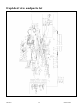
1
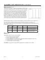
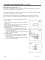
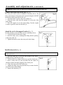
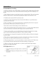
18" Scroll Saw
with Rotary Attachment
DO NOT RETURN TO STORE
Questions? Problems?
Please call our customer help line:
(888) 315-3080 M-F 8-5 CST or by
email:
[email protected]
SKU: 240-0041
Operation and Safety Instructions
Table of Contents
Technical data…………………………………………………………………………………….
2
General safety rules………………………………………………………………………………
3
Specific safety rules for the scroll saw…………………………………………………………...
5
Electrical information…………………………………………………………………………….
7
Know your scroll saw…………………………………………………………………………….
9
Assembly and adjustments……………………………………………………………………….
10
Operation…………………………………………………………………………………………
17
Maintenance………………………………………………………………………………………
21
Exploded view and parts list……………………………………………………………………………
22
Warranty…………………………………………………………………………………………..
25
Technical data
18" Scroll Saw with Rotary Attachment
240-0041
Motor:
120 V, 60 Hz, 2 A
Blade speed:
400-1,600 SPM
Rotary tool speed:
1,100-4,500 RPM
Maximum cutting capacity:
2” (5.1 cm) thick
Throat capacity:
18” (45.7 cm) long
Blade size:
5” (12.7 cm) pinned and pin-less
Blade stroke:
Work table bevel:
Work table size:
Rotary table size:
Chuck size:
3/4” (19 mm)
45º left and right
24-5/8”x13” (62.5x33 cm)
5-3/8”x7-1/16” (13.6x18 cm)
1/4” (6.35 mm)
240-0041
2
(888)315-3080
General safety rules
Safety is a combination of common sense, staying alert, and knowing how your power tool works.
SAVE THESE SAFETY INSTRUCTIONS.
WARNING: To avoid mistakes that could cause serious injury, do not plug in the power tool
until the following steps have been read and understood.
1. READ and become familiar with this entire instruction manual. LEARN the tool’s applications,
limitations, and possible hazards.
2. AVOID DANGEROUS CONDITIONS. Do not use power tools in wet or damp areas or expose
them to rain. Keep work areas well-lit.
3. DO NOT use power tools in the presence of flammable liquids or gases.
4. ALWAYS keep your work area clean, uncluttered, and well-lit. DO NOT work on floor surfaces
that are slippery.
5. KEEP BYSTANDERS AT A SAFE DISTANCE from the work area, especially when the tool is
operating. NEVER allow children or pets near the tool.
6. DO NOT FORCE THE TOOL to do a job that it was not designed to do.
7. DRESS FOR SAFETY. Do not wear loose clothing, gloves, neckties, or jewelry (rings,
watches, etc.) when operating the tool. Inappropriate clothing and items can get caught in
moving parts and draw you in. ALWAYS wear non-slip footwear and tie back long hair.
8. WEAR A FACE MASK OR DUST MASK as the operation produces dust.
WARNING: Dust generated from certain materials can be hazardous to your health. Always
operate this tool in a well-ventilated area and provide for proper dust removal. Use dust
collection systems whenever possible.
9. ALWAYS remove the power cord plug from the electrical outlet when making adjustments,
changing parts, cleaning, or working on the tool.
10. KEEP GUARDS IN PLACE AND IN WORKING ORDER.
11. AVOID ACCIDENTAL START-UPS. Make sure the power switch is in the OFF position before
plugging in the power cord.
12. REMOVE ADJUSTMENT TOOLS. Always make sure all adjustment tools are removed from
the power tool before turning it on.
240-0041
3
(888)315-3080
General safety rules
(continued)
13. NEVER LEAVE A RUNNING TOOL UNATTENDED. Turn the power switch to OFF. Do not
leave the tool until it has come to a complete stop.
14. NEVER STAND ON A TOOL. Serious injury could result if the tool tips or is accidentally hit.
DO NOT store anything above or near the tool.
15. DO NOT OVERREACH. Keep proper footing and balance at all times. Wear oil-resistant
rubber-soled footwear. Keep the floor clear of oil, scrap, and other debris.
16. MAINTAIN TOOLS PROPERLY. ALWAYS keep tools clean and in good working order.
Follow instructions for lubricating and changing accessories.
17. CHECK FOR DAMAGED PARTS. Check for alignment of moving parts, jamming, breakage,
improper mounting, or any other conditions that may affect the tool’s operation. Any part that is
damaged should be properly repaired or replaced before use.
18. MAKE THE WORKSHOP CHILDPROOF. Use padlocks and master switches and ALWAYS
remove starter keys.
19. DO NOT operate the tool if you are under the influence of drugs, alcohol, or medication that
could affect your ability to use the tool properly.
20. USE SAFETY GOGGLES AT ALL TIMES—that comply with ANSI
Z87.1. Normal safety glasses only have impact resistant lenses and are not
designed for safety. Wear a face or dust mask when working in a dusty
environment. Use ear protection, such as plugs or muffs, during extended
periods of operation.
240-0041
4
(888)315-3080
Specific safety rules for the scroll saw
WARNING: Do not operate the scroll saw until it is assembled, and you have read and
understand the following instructions and the warning labels on the scroll saw.
Before operating
1. Check for proper assembly and proper alignment of moving parts.
2. Understand the function and proper use of the ON/OFF switch.
3. Know the condition of the scroll saw. If any part is missing, bent, or does not operate properly,
replace the component before you use the scroll saw.
4. Determine the type of work you are going to be doing. Properly protect your body including your
eyes, hands, face and ears.
5. To avoid injury caused by pieces thrown accessories designed for this saw. Following the instructions
supplied with the accessory. The use of improper accessories may cause risk of injury.
6. To avoid contact with rotating equipment:
• Do not position your fingers where they could contact the blade if the workpiece should
unexpectedly shift or your hand should slip.
• Do not cut a workpiece too small to be held safety.
• Do not reach under the scroll saw table when the motor is running.
• Do not wear loose clothing or jewelry. Roll long sleeves above the elbow. Tie back long hair.
7. To avoid injury from accidental starting of the scroll saw:
• Make sure the switch is OFF and unplug the power cord from the electric outlet before changing
the blade, performing maintenance or making adjustment.
• Make sure the switch is OFF before plugging in the power cord to an electric outlet.
8. To avoid injury from a fire hazard, do not operate the scroll saw near flammable liquids, vapors or
gases.
9. To avoid back injury:
• Obtain help when it is necessary to raise the scroll saw more than 10 inches (25.4 cm). Bend your
knees when lifting the scroll saw.
• Carry the scroll saw by its base. Do not move the scroll saw by pulling on the power cord. Pulling
on the power cord could cause damage to the insulation or the wire connections resulting in
electric shock or fire.
240-0041
5
(888)315-3080
Specific safety rules for the scroll saw (continued)
When operating the scroll saw
WARNING: Use the rotary tool for sanding and grinding applications only. This
product is not recommended for drilling applications.
1. To avoid injury from unexpected scroll saw movement:
• Use the scroll saw on a firm level surface with adequate space for handling and supporting the
workpiece.
• Be sure the scroll saw cannot move when operated. Secure the scroll saw to a workbench or table
with wood screws or bolts with washers and nuts.
2. Before moving the scroll saw, unplug the power cord from the electric outlet.
3. To avoid injury from kickback:
• Hold the workpiece firmly against the tabletop.
• Do not feed the workpiece too fast while cutting. Only feed the workpiece at the rate the saw will cut.
• Install the blade with the teeth pointing downward.
• Do not start the saw with the workpiece pressing against the blade. Slowly feed the workpiece into
the moving blade.
• Use caution when cutting round or irregularly shaped work pieces. Round items will roll and
irregularly shaped work pieces can pinch the blade.
4. T avoid injury when operating the scroll saw:
• If you are not thoroughly familiar with the operation of scroll saws, obtain advice from a qualified
person.
• Before starting the saw, make sure the blade tension is correct. Recheck and adjust tension as need.
• Make sure the table is locked into position before starting the saw.
• Do not use dull or bent blades.
• When cutting a large workpiece, make sure the material is supported at the table height.
• Turn the saw OFF and unplug the power cord if the blade jams in the workpiece while being backed
out. This condition is usually caused by sawdust clogging the line you are cutting. If this happens,
turn OFF the scroll saw and unplug the power cord. Wedge open the workpiece and back out the
blade.
240-0041
6
(888)315-3080
Electrical information
Grounding instructions
IN THE EVENT OF A MALFUNCTION OR BREAKDOWN, grounding provides the path of least
resistance for electric current and reduces the risk of electric shock. This tool is equipped with an
electric cord that has an equipment grounding conductor and a grounding plug. The plug MUST be
plugged into a matching outlet that is properly installed and grounded in accordance with ALL local
codes and ordinances.
DO NOT MODIFY THE PLUG PROVIDED. If it will not fit the outlet, have the proper outlet
installed by a licensed electrician.
IMPROPER CONNECTION of the equipment grounding conductor can result in electric shock. The
conductor with the green insulation (with or without yellow stripes) is the equipment grounding
conductor. If repair or replacement of the electric cord or plug is necessary, DO NOT connect the
equipment grounding conductor to a live terminal.
CHECK with a licensed electrician or service personnel if you do not completely understand
the grounding instructions, or if you are not sure if the tool is properly grounded.
USE ONLY THREE-WIRE EXTENSION CORDS that
have 3-pronged plugs and outlets that accept the tool's
plug as shown in Fig. A. Repair or replace a damaged or
worn cord immediately.
Fig. A
1
3
2
- 3-prong
1. 3-pr1onged
plugplug 22.- Properly grounded
grounded outlet
outlet
3 - Grounding prong
3. Grounding prong
CAUTION: In all cases, make certain the outlet in question is properly grounded. If you are not sure if
it is, have a licensed electrician check the outlet.
240-0041
7
(888)315-3080
Electrical information
(continued)
WARNING: This power tool is for indoor use only. Do not expose to rain or use in damp
locations.
Guidelines for using extension cords
Make sure your extension cord is in good condition. When using an extension cord, be sure
to use one heavy enough to carry the current your product will draw. An undersized cord
will cause a drop in line voltage resulting in loss of power and overheating. The table below
shows the correct size to be used according to cord length and nameplate ampere rating. If in
doubt, use the next heavier gauge. The smaller the gauge number, the heavier the cord.
Minimum Gauge for Extension Cords (AWG)
(When using 120 V only)
Ampere rating
More than
Not more than
0
6
Total length of cord in feet (meters)
50 (15)
100 (30.4)
25 (7.6)
18
16
150 (45.7)
16
14
6
10
18
16
14
12
10
12
16
16
14
12
12
16
14
12
Not recommended
Make sure your extension cord is properly wired and in good condition. Always replace a
damaged extension cord or have it repaired by a qualified person before using it.
Protect your extension cords from sharp objects, excessive heat and damp or wet areas.
Use a separate electrical circuit for your tools. This circuit must not be less than a #12 wire
and should be protected with a 15 A time-delayed fuse. Before connecting the motor to the
power line, make sure the switch is in the OFF position and the electric current is rated the
same as the current stamped on the motor nameplate. Running at a lower voltage will
damage the motor.
WARNING: This tool must be grounded while in use to protect the operator from electric
shock.
240-0041
8
(888)315-3080
Know your scroll saw
A
B
C
D
E
F
G
H
I
J
On/off and light switches
Speed control knob
Dust blower and light
Lower blade holder
Bevel lock handle
Bevel adjustment knob
Base
Rotary tool cable
Rotary tool in clamp
Rotary tool dust port
K
L
M
N
O
P
Q
R
S
T
Rotary table
Blade tension lock lever
Rubber bearing cover
Motor
Storage compartment
Sawdust port
Saw table
Blade
Blade guard foot
Upper blade holder and knob
Assembly and adjustments
Unpacking (Fig. 1)
Unpack the scroll saw and all its parts, and compare against the list below. Do not discard the
carton or any packaging until the scroll saw is completely assembled.
CAUTION: Do not lift the saw by the arm that holds the blade. The saw will be damaged.
WARNING: To avoid injury from accidental starting, turn switch OFF and remove plug from
power source outlet before making any adjustments.
A
B
C
D
E
Scroll saw
Rotary tool
Rotary table with dust port (Assembled on the scroll saw)
Rotary table insert
Chuck key
Not shown:
Pin-less blade (1)
Allen wrench (3mm, 4mm & 5mm)
Extra brush (1 set)
Storage compartment (Fig. 2)
A storage location (1) for small accessories
240-0041
10
(888)315-3080
Assembly and adjustments
(continued)
Align the bevel indicator (Fig. 3-5)
The bevel indicator has been factory adjusted, it should be rechecked prior to use for best
operation.
1. Remove the blade guard foot (1) using a hex key
to loosen the screw (2).
2. Loosen the table bevel lock handle (3) and turn
the table adjustment knob (4) to move the table
until it is approximately at a right angle to the
blade.
3. Use a combination square (5) (not provided) to
set the table exactly 90º to the blade (6). If there
is space between the square and the blade adjust
the table angle until the space is closed.
4. Tighten the table bevel lock handle (3) to prevent
movement.
5. Loosen the screw (7) holding the bevel scale
pointer and position pointer to 0º. Tighten the
screw.
6. Attach the blade guard foot (1) and tighten the
screw (2).
240-0041
11
(888)315-3080
Assembly and adjustments
(continued)
WARNING: to reduce the risk of injury:
• When carrying the saw, hold it close to your body to avoid injury to your back. Bend your knees
when lifting the saw.
• Carry the saw by the base. Do not carry the saw by the power cord.
• Secure the saw in a position where people cannot stand, sit, or walk behind it. Debris thrown
from the saw could injure people standing, sitting, or walking behind it.
• Secure the saw on a firm, level surface where the saw cannot rock and there is adequate room for
handling and properly supporting the workpiece.
Blade guard foot adjustment (Fig. 6)
When cutting at angles, the blade guard foot should be adjusted so it is parallel to the table and rests flat
above the workpiece.
1. To adjust, loosen the screw (2), tilt the foot (1) so it is parallel to the
table, and tighten the screw.
2. Loosen the height adjustment knob to raise or lower the foot until it
just rests on top of the workpiece. Tighten the knob.
3. Loosen the horizontal adjustment knob (4) and move the foot
forward or backward as needed.
Attach the rotary tool table (Fig. 7 and 8)
1. Secure the rotary tool table (1) to the side of the saw using the four hex screws (2) and washers provided
with the table.
2. Place the rotary table insert (3) in the opening on the rotary
table.
Note: The rotary tool (4) attaches to the clamp located below the
rotary tool table.
240-0041
12
(888)315-3080
Assembly and adjustments
(continued)
Sawdust collection port (Fig. 9 and 10)
This scroll saw allows a hose or vacuum accessory (not provided)
to be connected to the dust chute (1) at the front of the saw and to
the dust chute (2) under the rotary tool table (30, if installed.
If excessive sawdust buildup occurs inside the base, use a wet/dry
vacuum cleaner or manually remove sawdust. This will keep your
saw cutting efficiently.
Adjusting the dust blower/light (Fig. 11)
For best results, the dust blower tube (1) should be adjusted to
direct air and light at the blade and workpiece.
240-0041
13
(888)315-3080
Assembly and adjustments
(continued)
Blade selection (Fig. 12)
This scroll saw accepts 5" length pin-end and pinless blades, with a
wide variety of blade thicknesses and widths. The type of material
and intricacies of cutting operations will determine the number of
teeth per inch. Always select the narrowest blades for intricate
(tight radius and curves) curve cutting and the widest blades for
straight and large curve cutting operations. The following table
represents suggestions for various materials. When purchasing
blades, refer to the back of the package for best use of blades on
various materials. Use this table as an example, but practice and
your own personal preference will be the best selection method.
When choosing a blade, use very fine, narrow blades to scroll cut in thin wood 1/4" thick or less.
Use wider blades for thicker materials but this will reduce the ability to cut tight curves.
Note: Thinner blades will have more possibilities for blade deflection when cutting angles are not
perpendicular to the table.
Teeth /inch
TPI
10-15
Blade width
Inch
0.110
Blade thickness
Inch
0.018
Blade/SPM
Material cut
500-1200
15-28
0.055-0.110
0.010-0.018
800-1700
30-48
0.024-0.041
0.012-0.019
Varies
Medium turns on ¼” to 1-3/4”
wood, soft metal, hardwood
Small turns on 1/8” to 1-1/2”
wood, soft metal, hardwood
Non-ferrous metal/hardwoods
using very slow speeds
Blade Care
To maximize the life of your scroll saw blades:
1.
2.
3.
4.
5.
Do not bend blades when installing.
Always set proper blade tension.
Use the right blade (see instructions on replacement blade packaging for proper use.)
Feed the workpiece correctly into the blade.
Use thin blades for intricate cutting.
CAUTION: Any and all servicing should be performed by a qualified service center.
240-0041
14
(888)315-3080
Assembly and adjustments
(continued)
Blade removal and installation (Fig. 13-15)
WARNING: To prevent personal injury, always turn saw OFF and disconnect the plug from the power
source before changing blades or making adjustments.
This saw uses pin-end and pin-less blades. Pin-end blades are thicker for stability and for faster assembly.
They provide faster cutting on a variety of materials.
Note: When installing pin-end blades, the slot on the blade holder must be slightly wider than the
thickness of the blade. After the blade is installed, the blade tension mechanism will keep it in place.
1. Loosen the blade tension by raising the blade tension lock lever (1).
2. To remove a blade:
Pinned: Lift the blade (2) out and away from the upper and lower
blade holders (3).
Pin-less: Loosen the upper and lower blade holders (3), and lift the
blade out and away from the blade holders.
CAUTION: Install the blade with the teeth pointed downward.
3. Install a pinned blade:
a. Hook a blade (2) in the recess of the lower blade holder.
b. Press down on the upper blade holder and insert the blade
into the slot on the upper holder.
c. Lower the blade tension lock lever (1). Make sure the blade is
properly located in the blade holders.
4. Install a pinless blade:
a. Place a blade (2) in the upper and lower blade holders (3).
b. Tighten the lower and upper blade knobs (4) by hand or
provided allen wrench.
c. Lower the blade tension lock lever (1). Make sure the blade is
properly located in the blade holders.
240-0041
15
(888)315-3080
Assembly and adjustments
(continued)
WARNING: Remove the saw blade before installing and/or using the rotary tool.
Connect the rotary tool to the saw (Fig. 16)
The rotary tool can be used as a handheld or stationary device. The
rotary tool connects to the motor and is operated using the ON/OFF
switch and variable speed dial on the saw.
1. Open the latch (1) on the rotary tool coupler (2).
2. Insert the inner cable into the opening (3) at the end of the
motor fitting.
3. Place the coupler (2) over the motor fitting. Turn the coupler
to ensure a good fit, and close the latch (1).
Attach the tool to the support bracket (Fig. 17)
Use this procedure to use the rotary tool as a stationary device.
1. Loosen the knob on the rotary clamp.
2. Insert the rotary tool (1) through the clamp and the opening
in the rotary table (2).
3. Tighten the knob to secure the rotary tool in the clamp.
Install rotary tools (Fig. 18)
WARNING: Use the rotary tool for sanding and grinding applications only. This product is not recommended for
drilling applications.
1. Place the chuck key (1) into the side keyhole of the chuck,
meshing the key with the gear teeth.
2. Turn the chuck key counterclockwise to open the chuck jaws.
3. Insert a rotary tool (2) (not provided) into the chuck far
enough to obtain maximum gripping of the chuck jaws.
4. Center the rotary tool in the chuck jaws.
5. Tighten the chuck jaws using the chuck key to ensure that the
tool will not slip while drilling.
6. Remove the chuck key (1).
Operation
Recommendations for cutting
A scroll saw is basically a curve-cutting machine. It can also be used for straight cutting and beveling
or angle cutting operations. Please read and understand the following items before attempting to use
the saw.
1. When feeding the workpiece into the blade do not force it against the blade. This could cause blade
deflection. Allow the saw to cut the material by guiding the workpiece into the blade as it cuts.
2. The blade teeth cut material ONLY on the down stroke.
3. Guide the wood into the blade slowly because the teeth of the blade are very small and remove
wood only on the down stroke.
4. There is a learning curve for each person using this saw. During that period of time it is expected
that some blades will break until you learn how to use the saw.
5. Best results are achieved when cutting wood one inch thick or less.
6. When cutting wood thicker than one inch, guide the wood very, very slowly into the blade and take
extra care not to bend or twist the blade while cutting in order to maximize blade life.
7. Teeth on scroll saw blades wear out and the blades must be replaced frequently for best cutting
results. Scroll saw blades generally stay sharp for 1/2 hour to 2 hours of cutting.
8. To get accurate cuts, be prepared to compensate for the blade's tendency to follow the wood grain
as you are cutting.
9. This scroll saw is primarily designed to cut wood or wood products. For cutting precious and nonferrous metals, the variable control switch must be set at very slow speeds.
10. When choosing a blade, use very fine, narrow blades to scroll cut in thin wood 1/4" thick or less.
Use wider blades for thicker materials but this will reduce the ability to cut tight curves.
11. Blades wear faster when cutting plywood or very abrasive particle board. Angle cutting in
hardwoods wears blades down faster.
LED Light switch (Fig. 19)
1. To turn on the light, press the light switch (1) to the ON (I)
position.
2. To turn OFF the light, press the light switch (1) to the OFF
(O) position.
240-0041
17
(888)315-3080
Operation (continued)
ON/OFF switch and speed control knob (Fig. 20)
Always wait for the saw or rotary to come to a complete stop before restarting.
1. To turn the saw or rotary on, press the switch (1) to the ON (I)
position.
2. Turn the variable speed knob (2) to adjust the blade speed or
rotary speed to the desired setting. Turning the control knob
clockwise increases speed; turning it counterclockwise reduces
speed.
3. To turn the saw off, press the switch (1) to the OFF (O) position.
Note: A small lock may be placed between the power switch and the
plastic switch guard (3) to prevent accidental operation. It is
recommended to lock the saw when not in use.
WARNING: To avoid injury from accidental start-ups, always turn the switch OFF and unplug the
scroll saw before moving the tool, replacing the blade, or making adjustments.
Freehand cutting (Fig. 21)
1. Lay out desired design, or secure design to the workpiece.
2. Raise the blade guard foot (1) by loosening the height
adjustment knob (2).
3. Position the workpiece against the blade and place the
blade guard foot against the top surface of the workpiece.
4. Secure the blade guard foot (1) by tightening the height
adjustment knob (2).
5. Remove the workpiece from the blade prior to turning the
scroll saw ON.
CAUTION: In order to avoid uncontrollable lifting of the
workpiece and to reduce blade breakage, do not turn the
switch on while the workpiece is against the blade.
6. Slowly feed the workpiece into the blade by guiding and
pressing the workpiece down against the table.
CAUTION: Do not force the leading edge of the workpiece into the blade. The blade will deflect,
reducing accuracy of cut, and may break.
7. When the cut is complete, move the trailing edge of the workpiece beyond the blade guard foot. Turn
the switch OFF.
240-0041
18
(888)315-3080
Operation (continued)
Angle cutting (bevel cutting) (Fig. 22)
1. Layout or secure design to workpiece.
2. Move the blade guard foot to the highest position by loosening
3.
4.
5.
6.
7.
the height adjustment knob (1). Retighten.
Tilt the table to the desired angle by loosening the table bevel
lock handle (2) and moving the table to the proper angle using
the degree scale and the pointer (3).
Tighten the table bevel lock handle (2).
Loosen the blade guard screw, and tilt the blade guard to the
same angle as the table. Retighten the blade guard screw. See
Hold down clamp adjustment'.
Position the workpiece on the right side of the blade. Lower the
blade guard foot against the surface by loosening the height
adjustment knob. Retighten.
Follow steps 5-7 under Freehand cutting.
Interior cutting (Fig. 23)
1. Lay out the design on the workpiece. Drill a 1/4" hole in the
workpiece.
2. Remove the blade. See Blade removal and installation.
3. Place the workpiece on the saw table with the hole in the
workpiece over the access hole in the table.
4. Install a blade through the hole in the workpiece.
5. Follow steps 3-7, under Freehand cutting.
6. When finished making the interior scroll cuts simply turn the
scroll saw OFF. Unplug the saw before removing the blade
from the blade holder. Remove the workpiece from the table.
240-0041
19
(888)315-3080
Operation (continued)
Rip or straight line cutting (Fig. 24)
1. Raise the blade guard foot (1) by loosening the height
adjustment knob (2).
2. Measure from the tip of the blade to the desired distance.
Position the straight edge parallel to the blade at that distance.
3. Clamp the straight edge to the table.
4. Recheck your measurements using the workpiece to be cut
and make sure the straight edge is secure.
5. Position the workpiece against the blade and place the blade
guard foot against the top surface of the workpiece.
6. Secure the blade guard foot in place by tightening the height
adjustment knob.
7. Remove the workpiece from the blade prior to turning the
scroll saw ON.
CAUTION: In order to avoid uncontrollable lifting of the workpiece and reduce blade breakage, do
not turn the switch on while the workpiece is against the blade.
8. Position the workpiece against the straight edge prior to touching the leading edge of the
workpiece against the blade.
9. Slowly feed the workpiece into the blade, guiding the workpiece against the straight edge and
pressing the workpiece down against the table.
CAUTION: Do not force the leading edge of the workpiece into the blade. The blade will deflect;
reducing accuracy of cut, and may break.
10. When the cut is complete, move the trailing edge of the workpiece beyond the blade guard foot.
Turn the switch OFF.
Quantity
2
1
1
240-0041
Tool needed
Description
Small C-clamp
Ruler or measuring tape
12” straight scrap of wood
(thickness to match workpiece)
20
(888)315-3080
Maintenance
WARNING: Always turn the switch OFF and unplug the power cord from the outlet before
maintaining or lubricating the scroll saw.
To ensure that the wood glides smoothly across the work surface, periodically apply a coat of paste
wax to the surface of the worktable. If the power cord is worn out or damaged in any way, replace it
immediately. Do not attempt to oil the motor bearings or service the motor's internal parts.
Lubrication
Lubricate the arm bearings after every 50 hours of use.
1. Turn the saw on its side and remove the cover.
2. Squirt a generous amount of SAE 20 oil (lightweight motor oil) around the shaft and bearing.
3. Let the oil soak in overnight.
4. Repeat the above procedure for the opposite side of the saw.
Brushes (Fig. 25)
Check the condition of the carbon brushes after 50 hours of
use. If the brushes are worn to 1/16” (2mm) in length,
replace them.
1. Loosen and remove the two brush caps (1) using a
flat-blade screwdriver.
2. Pull out each brush (2), inspect the brush and
replace if necessary. Replace both brushes even if
only one is damaged.
Note: After inspecting the brushes, be sure to install the
brushes into the same position that they were removed
from if you are not installing new ones.
3. Position the brushes into the motor. Tighten the
brush caps (1) snugly. Do not over tighten.
4. Run the saw for approximately 5 to 10 minutes to allow the brushes to “seat” themselves. If
the brushes are not seated correctly, the electric brake may not function correctly and could
damage the motor. While the brushes are seating, some sparking may be noticed in the motor.
This is normal for new brushes.
240-0041
21
(888)315-3080
Exploded view and parts list
240-0041
22
(888)315-3080
Exploded view and parts list (continued)
Part#
1
2
3
4
5
6
7
8
9
10
11
12
13
14
15
16
17
18
19
20
21
22
23
24
25
26
27
28
29
30
31
32
33
34
35
36
37
38
39
40
240-0041
Order #
240-0041-001
240-0041-002
240-0041-003
240-0041-004
240-0041-005
240-0041-006
240-0041-007
240-0041-008
240-0041-009
240-0041-010
240-0041-011
240-0041-012
240-0041-013
240-0041-014
240-0041-015
240-0041-016
240-0041-017
240-0041-018
240-0041-019
240-0041-020
240-0041-021
240-0041-022
240-0041-023
240-0041-024
240-0041-025
240-0041-026
240-0041-027
240-0041-028
240-0041-029
240-0041-030
240-0041-031
240-0041-032
240-0041-033
240-0041-034
240-0041-035
240-0041-036
240-0041-037
240-0041-038
240-0041-039
240-0041-040
Description
Screw ST4.2×12
Cover
Screw M4x12
Washer 4
Screw ST2.9×8
Circuit Board
Left Side Cover
Belt
Base
Power Cord Sleeve
Bolt M6x70
Washer 8
Bolt M8 x 25
Power Cord
Washer 5
Screw M5x25
Bolt M5x16
Spring Washer 5
Rotary Tool Dust Port
Screw M5x25
Rotary Table Support
Rotary Table
Rotary Table insert
Clamp Knob
Clamp
Screw M5x10
Dust Port
Left Housing
Knob
Plastic Cap
Hold Down Rod
Hold Down Bracket
Blade Guard Foot
Washer 6
Screw M6x10
Spring
Upper Retainer
Upper Rocker Arm
Tension Bolt
Screw M6x30
Qty
6
1
8
16
2
1
1
1
1
1
1
10
4
1
12
4
2
6
1
4
1
1
1
1
1
2
1
1
2
6
1
1
1
6
1
1
1
1
1
2
23
Part#
41
42
43
44
45
46
47
48
49
50
51
52
53
54
55
56
57
58
59
60
61
62
63
64
65
66
67
68
69
70
71
72
73
74
75
76
77
78
79
80
Order #
240-0041-041
240-0041-042
240-0041-043
240-0041-044
240-0041-045
240-0041-046
240-0041-047
240-0041-048
240-0041-049
240-0041-050
240-0041-051
240-0041-052
240-0041-053
240-0041-054
240-0041-055
240-0041-056
240-0041-057
240-0041-058
240-0041-059
240-0041-060
240-0041-061
240-0041-062
240-0041-063
240-0041-064
240-0041-065
240-0041-066
240-0041-067
240-0041-068
240-0041-069
240-0041-070
240-0041-071
240-0041-072
240-0041-073
240-0041-074
240-0041-075
240-0041-076
240-0041-077
240-0041-078
240-0041-079
240-0041-080
Description
Screw M5x25
Screw M6x20
Sleeve
Washer
Flat Washer 6
Blade Tension Lock Lever
Spring Pin M3x20
Left Carrying Handle
Switch Cover
ON/OFF Switch
Speed Control Knob
Speed Control Label
Right Carrying Handle
Nut M5
Nut M6
Right Housing
Cord Clamp
Screw M4x8
Spring Pin M5x12
Blade Holder
Blade
Screw M6x5
Lower Retainer
Nut M3
Spring Washer 3
Flat Washer 3
Bearing Washer (A)
Clamp Plate
Bearing 625-2Z
Connecting Link
Bearing Washer (B)
Cam
Screw M3x12
Flat Washer
Wheel
Retainer Sleeve
Screw M5x16
Wheel Shaft
Bearing
Snap Ring 32
(888)315-3080
Qty
4
2
1
1
2
1
1
1
1
1
1
1
1
4
2
1
4
4
4
2
1
3
1
1
1
1
1
2
2
1
1
1
1
1
1
1
2
1
2
1
Exploded view and parts list (continued)
Part #
81
82
83
84
85
86
87
88
89
90
91
92
93
94
95
96
97
98
99
100
101
102
103
104
105
106
107
108
109
110
111
112
113
114
115
116
117
118
119
120
240-0041
Order #
240-0041-081
240-0041-082
240-0041-083
240-0041-084
240-0041-085
240-0041-086
240-0041-087
240-0041-088
240-0041-089
240-0041-090
240-0041-091
240-0041-092
240-0041-093
240-0041-094
240-0041-095
240-0041-096
240-0041-097
240-0041-098
240-0041-099
240-0041-100
240-0041-101
240-0041-102
240-0041-103
240-0041-104
240-0041-105
240-0041-106
240-0041-107
240-0041-108
240-0041-109
240-0041-110
240-0041-111
240-0041-112
240-0041-113
240-0041-114
240-0041-115
240-0041-116
240-0041-117
240-0041-118
240-0041-119
240-0041-120
Description
Snap Ring 12
Screw M4x30
Wheel
Screw M5x8
Motor
Tool Box Cover
Dust Blower
Air Nozzle
Table Insert
Saw Table
Bevel Scale
Gear
Bevel Adjustment Knob
Table Bevel Lock Handle
Spring
Bolt
Bolt
Spring Washer 8
Screw M8x20
Lock Bolt
Rotary Connect
Locking Knob
Roll Pin
Spring
Shaft
Sawdust Port
Screw M4x16
Pointer
Pointer Holder
bracket
Cord Clamp
Spring Tube
Flex Shaft
Rotary Tool
Nut M8
Rubber Foot
Washer 15
Bearing
Sleeve
Bearing
Qty
1
2
1
1
1
1
1
1
1
1
1
1
1
1
1
1
1
6
2
1
1
1
1
2
1
1
2
1
1
1
1
1
1
1
4
4
1
1
1
1
24
Part #
121
122
123
124
125
126
127
128
129
130
131
132
133
134
135
136
137
138
139
140
141
142
Order #
240-0041-121
240-0041-122
240-0041-123
240-0041-124
240-0041-125
240-0041-126
240-0041-127
240-0041-128
240-0041-129
240-0041-130
240-0041-131
240-0041-132
240-0041-133
240-0041-134
240-0041-135
240-0041-136
240-0041-137
240-0041-138
240-0041-139
240-0041-140
240-0041-141
240-0041-142
Description
Rotary Shaft
Chuck
Clamp Clip
LED Light
Screw M6x16
Spring Washer 6
Air Hose
Pressure Plate
Air Bag
Spring Pin M4x8
Table Rock
Screw M5x16
Screw M5x16
Copper Sleeve
LED Circuit Board
Screw ST2.9x6
Lower Rocker Arm
Light Switch
Chuck Key
Wrench 4
Wrench 5
Wrench 3
Qty
1
1
1
1
4
5
1
1
1
1
1
2
5
4
1
2
1
1
1
1
1
1
(888)315-3080
Warranty
MASTERFORCE™ SCROLL SAW WARRANTY
3-MONTH MONEY BACK GUARANTEE:
This MASTERFORCE™ brand power tool carries our 3-Month Money Back Guarantee. If you are not
completely satisfied with your MASTERFORCE™ brand power tool for any reason within three (3)
months from the date of purchase, return the tool with your original receipt to any
retail
store, and we will provide you a refund – no questions asked.
3-YEAR LIMITED WARRANTY:
This MASTERFORCE™ brand power tool carries our famous No Hassle 3-Year Limited Warranty to the
original purchaser. If the tool fails within three (3) years from the date of purchase, simply bring this tool
and its sale receipt back to your nearest
retail store for a free equivalent replacement
within those three years. Notwithstanding the foregoing, this limited warranty does not cover any
damage that has resulted from abuse or misuse of the Merchandise. This warranty: (1) excludes
expendable parts including but not limited to blades, belts, bits, light bulbs, and/or batteries; (2) shall be
void if this tool is used for commercial and/or rental purposes; and (3) does not cover any losses, injuries
to persons/property or costs. This warranty does give you specific legal rights and you may have other
rights, which vary from state to state. Be careful, tools are dangerous if improperly used or maintained.
Seller’s employees are not qualified to advise you on the use of this Merchandise. Any oral
representation(s) made will not be binding on seller or its employees. The rights under this limited
warranty are to the original purchaser of the Merchandise and may not be transferred to any subsequent
owner. This limited warranty is in lieu of all warranties, expressed or implied including warranties or
merchantability and fitness for a particular purpose. Seller shall not be liable for any special, incidental,
or consequential damages. The sole exclusive remedy against the seller will be for the replacement of
any defects as provided herein, as long as the seller is willing or able to replace this product or is willing
to refund the purchase price as provided above. For insurance purposes, seller is not allowed to
demonstrate any of these power tools for you.
For questions / comments, technical assistance or repair parts –
Please Call Toll Free at: 1-888-315-3080 (M-F 8am – 5pm) CST
SAVE YOUR RECEIPTS.
THIS WARRANTY IS VOID WITHOUT THEM.
Printed in China
240-0041
25
(888)315-3080