1
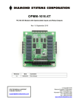
OPT MACHINE VISION TECH.CO. LTD
ADD:8 JingSheng Road, JingXia ChangAn DongGuan China 523853
TEL: 0769-82716188
FAX: 0769-81606698
E-mail:[email protected]
Website:Http://www.optmv.net
OPT-DPA1024E-4
LED lighting controller manual
OPT MACHINE VISION TECH.CO.,LTD.
Revised in Dec.2014
1
OPT MACHINE VISION TECH.CO. LTD
ADD:8 JingSheng Road, JingXia ChangAn DongGuan China 523853
TEL: 0769-82716188
FAX: 0769-81606698
E-mail:[email protected]
Website:Http://www.optmv.net
Copyright reserved
1、All the logos and names in this manual belong to OPT.
2、All copyright reserved by OPT company, the original author. Replication and distribution of the contents in any form,
anywhere without permission from our company is straightly prohibited. Revisions are subject to change without prior notice.
Caution and warning:
Caution and Warning
This product should be connected to 220V AC power supply. Please ensure that the power
switch controller is off when plugging in/out the power to prevent against electric shock.
Please read the manual carefully in advance and strictly follow the instructions when operating
the product.
In case of any abnormal situation, please contact us and never disassemble the product by
yourself.
Please make sure good ground for the controller to avoid electric shock.
Do not stare directly into the light given out from the LED since it do harm to your eyes. If a
specular object is used, please take care not to let reflected light to enter your eyes.
2
OPT MACHINE VISION TECH.CO. LTD
ADD:8 JingSheng Road, JingXia ChangAn DongGuan China 523853
TEL: 0769-82716188
FAX: 0769-81606698
E-mail:[email protected]
Website:Http://www.optmv.net
Contents
1、Overview ··················································································································5
1.1 Profile ···················································································································5
1.2 Selection guidance ····································································································5
1.2.1 Accessory selection guidance ···················································································5
1.3 Parameter description ·······························································································6
1.4 Panel description ·····································································································7
1.5 Function description ·································································································8
1.5.1 Automatically/Manually checking/setting the maximum current ··········································8
1.5.2 General/ Highlight trigger mode ················································································8
1.5.3 Error code ··········································································································8
1.5.4 Working mode switch ····························································································9
2、Installation Guidance·································································································10
2.1 DIN guide rail installation ························································································11
2.2 Screw installation ···································································································11
2.3 Installation size ······································································································11
3、Operation Instructions ·······························································································12
3.1 Wiring diagram ·····································································································12
3.2 Turn on light source ································································································12
3.3 Setting intensity ·····································································································13
3.4 External trigger ·····································································································13
4、Software Operation Instructions···················································································14
4.1 Software interface description ···················································································14
4.2 Software function description ····················································································18
5、Appendix A: Mechanical parameter ··············································································19
6、Appendix B: Programming Manual ··············································································23
1. Overview ···············································································································23
1.1. Configuration ······································································································23
1.2. Controller default settings ·······················································································23
1.3. Programming flowchart ··························································································23
3
OPT MACHINE VISION TECH.CO. LTD
ADD:8 JingSheng Road, JingXia ChangAn DongGuan China 523853
TEL: 0769-82716188
FAX: 0769-81606698
E-mail:[email protected]
Website:Http://www.optmv.net
1.4. Example programs ································································································24
2. Function Specification·······························································································27
2.1. Initializing a serial port ··························································································27
2.2. Releasing a serial port····························································································27
2.3. Creating an Ethernet connection (by IP) ······································································28
2.4. Creating an Ethernet connection (by SN) ·····································································28
2.5. Destroying an Ethernet connection ············································································29
2.6. Turning on channel(s) ····························································································29
2.7. Turning on multiple channels ···················································································30
2.8. Turning off channel(s) ···························································································30
2.9. Turning off multiple channels ···················································································31
2.10. Setting intensity ·································································································31
2.11. Setting multiple intensity ······················································································32
2.12. Reading intensity ································································································32
2.13. Setting the trigger pulse width ················································································33
2.14. Setting multiple trigger pulse width ··········································································33
2.15. Reading the trigger pulse width ···············································································34
2.16. Setting high brightness trigger pulse width ·································································34
2.17. Setting multiple high brightness trigger pulse width·······················································35
2.18. Reading the high brightness trigger pulse width ···························································35
2.19. Enable response ·································································································36
2.20. Enable checksum ································································································36
2.21. Enable back up when power off ···············································································36
2.22. Reading serial number ··························································································37
2.23. Reading IP configuration ·······················································································37
3. Appendices ·············································································································38
A FAQ (frequently asked questions) ··············································································38
B Macro Definitions for Error Codes ·············································································38
C Acronyms ··········································································································39
4
OPT MACHINE VISION TECH.CO. LTD
ADD:8 JingSheng Road, JingXia ChangAn DongGuan China 523853
TEL: 0769-82716188
FAX: 0769-81606698
E-mail:[email protected]
Website:Http://www.optmv.net
1、Overview
1.1 Profile
This digital power controller unit (No: OPT-DPA1024-4) is a digital constant current controller which possesses the
following functions: 256-levelled intensity adjustment (The adjustment for each channel is independent.); highlight triggering;
general triggering; trigger delay; automatically checks for light source maximum current (hot swapping light source);
manually setting the maximum output current; 100M Ethernet communication; RS232 communication.
1.2 Selection guidance
OPT - DPA 10 24 E - 4
Channel amount: 4
E: Network interface type: Ethernet
Output voltage: 24V
Input voltage: 1A
Controller type: digital current
Company name
1.2.1 Accessory selection guidance
1、Network cable:
Factory standard network cable: CAT6 or later, 3m length
Cable requirement: CAT6 or later, no longer than 50m
2、Router or switch
Choose well-known brands. The transmission speed is no less than 100Mbps
recommended type:
Router: NETGEAR (from USA) WGR614 (150Mbps)
Switch: NETGEAR (from USA) FS308(8 ports, 100M)
5
OPT MACHINE VISION TECH.CO. LTD
ADD:8 JingSheng Road, JingXia ChangAn DongGuan China 523853
TEL: 0769-82716188
FAX: 0769-81606698
E-mail:[email protected]
Website:Http://www.optmv.net
1.3 Parameter description
Item
Parameter
Input voltage
AC: 100-240V
Automatically checks
for load maximum
current
Connects 10mA-1A, 24V light source
Manually set the
maximum output
current
Range: 10mA - 1A
Adjustable intensity
level
256
Adjusted via front panel encoder or
software
Enabled
If the controller is short-circuited, the
short-circuit protection will turn off the
corresponding channel with error message
“ER2” from LED.
Overcurrent protection
Enabled
If overcurrent occurs, the overcurrent
protection will turn off the corresponding
channel with error message “ER1” from
LED.
General trigger mode
Intensity level: 0-255, adjustable
See Sect.1.5.6
Highlight trigger mode
The current is 1A for single channel.
See Sect.1.5.6
General trigger delay
1-999ms
Configurable by front panel encoder or
software
Highlight trigger delay
0.01-5.00ms
Configurable by front panel encoder or
software
Load capacity
1A/CH 2.2A/4CH
Can only connect 24V light source
Communication mode
RS232/Ethernet
Temperature controlled
fan
Fan activate at 20℃ and reaches
maximum RPM at 30℃.
Standby power
<3W
Insulation
AC 1500V at 1Min
leakage current < 10mA
Insulation resistance
DC 500V
Insulation resistance >20MΩ
Working temperature
-5-50℃
Short-circuit protection
Remark
6
OPT MACHINE VISION TECH.CO. LTD
ADD:8 JingSheng Road, JingXia ChangAn DongGuan China 523853
Dimension size
91*134.41*171mm
Weight
1kg
TEL: 0769-82716188
FAX: 0769-81606698
E-mail:[email protected]
Website:Http://www.optmv.net
1.4 Panel description
6、encoder
3、serial port
7、light source interface
2、working mode switches
4、100M Ethernet port
8、trigger port
Fig.1.1: front panel
9、power switch
Index
Panel
Description
Remark
1
4-digit LED
From left to right, the 1st digit equals the
channel index and the remaining three
digits are decimal representation of the
corresponding channel parameter. See
Sect.3.3 & 3.4.
2
Working mode switch
Switch working mode, see Sect. 1.5.6
3
Serial port
For communication with PC via RS232
4
100M Ethernet port
For communication with PC via Ethernet
7
OPT MACHINE VISION TECH.CO. LTD
ADD:8 JingSheng Road, JingXia ChangAn DongGuan China 523853
TEL: 0769-82716188
FAX: 0769-81606698
E-mail:[email protected]
Website:Http://www.optmv.net
5
AC input
Input: AC 100-240V 50/60Hz
6
Encoder
Adjust intensity and trigger delay
7
Light source interface
4 light source output and they are
independent with each other
8
Trigger port
Connected to external trigger source and
perform synchronous strobe
9
Power switch
Turn on/off controller power supply
The trigger delay is adjustable
1.5 Function description
1.5.1 Automatically/Manually checking/setting the maximum current
This feature is enabled by software only. By default the controller will automatically adjust the controller to light
sources with current 10mA-1A and voltage 24V. This feature can be overridden by software.
1.5.2 General/ Highlight trigger mode
The controller can enter the two modes by turning the working mode switches accordingly (For general trigger mode
switch 1 “OFF”, switch 2 “ON” while for highlight trigger mode, both switch 1 and switch 2 are “OFF”). Set the trigger
delay through adjusting the encoder or software. The range of the adjustable intensity is 0-255. Optocoupler isolation is built
in. For voltage 0-4V, the optocoupler isolation is not conductive and it becomes conductive when the voltage is within 7 -24V.
For default, it is positive edge triggered.
1.5.3 Error code
Code
ER0
Error description
Reaction
Recover
Not connected to any
light source
ER1
Overcurrent
ER2
Short-circuit
ER3
Overvoltage
Launch the overcurrent protection for the
corresponding channel and turn it off.
Launch the short-circuit protection for the
corresponding channel and turn it off
Launch the overvoltage protection for the
corresponding channel and turn it off.
8
Correct error and reboot
Correct error and reboot
Correct error and reboot
OPT MACHINE VISION TECH.CO. LTD
ADD:8 JingSheng Road, JingXia ChangAn DongGuan China 523853
TEL: 0769-82716188
FAX: 0769-81606698
E-mail:[email protected]
Website:Http://www.optmv.net
1.5.4 Working mode switch
Mode
Switch 1
Switch 2
General lighting mode
ON
ON
Automatically checks for load current once
ON
OFF
General trigger mode
OFF
ON
Highlight trigger mode
OFF
OFF
Note:(1) DPA1024E-4 controller can only connect 24V light source.
(2) The maximum current is 1A for single channel and 2.2A for 4 channels.
(3) When manually setting the maximum output current, never connect the controller to the light source with
current lower than the maximum output current. Otherwise, it may damage the light source because of current
mismatch.
(4) Automatically checks for load current once mode: When turning to this mode, the controller will recheck the
load maximum current once.
9
OPT MACHINE VISION TECH.CO. LTD
ADD:8 JingSheng Road, JingXia ChangAn DongGuan China 523853
TEL: 0769-82716188
FAX: 0769-81606698
E-mail:[email protected]
Website:Http://www.optmv.net
2、Installation Guidance
Index
Interface
Description
Remark
1
Screw hole
Install screw
2
DIN rail track
Standard DIN rail installation
10
OPT MACHINE VISION TECH.CO. LTD
ADD:8 JingSheng Road, JingXia ChangAn DongGuan China 523853
TEL: 0769-82716188
FAX: 0769-81606698
E-mail:[email protected]
Website:Http://www.optmv.net
2.1 DIN guide rail installation
1、Installation (Fig.2.1): (1) Lock the controller back panel DIN rail track to position 1 rail.
(2) Push down controller toward position 2.
position 1
position 2
Fig.2.2: Guide rail Uninstallation
Fig. 2.1: Guide rail installation
2、Uninstallation (Fig.2.2): (1) Pull down the controller.
(2) Push up toward position1.
2.2 Screw installation
Installation (Fig.2.3):
1、Secure back-plate against controller.
2、Tighten the screws.
3、Tighten the back-plate to fixtures or stations.
Fig.2.3: Screws installation
2.3 Installation size
Fig.2.4: DIN guide rail size
Fig.2.5: Screw size
11
OPT MACHINE VISION TECH.CO. LTD
ADD:8 JingSheng Road, JingXia ChangAn DongGuan China 523853
TEL: 0769-82716188
FAX: 0769-81606698
E-mail:[email protected]
Website:Http://www.optmv.net
3、Operation Instructions
3.1 Wiring diagram
PC
light source
RS232/Ethernet port
light source interface
light source controller
power supply input
trigger interface
接口
trigger signal
AC100-240V
Figure 6: Wiring diagram
Step1: Connect the light source to controller (See Fig. 6).
Step2: If the external trigger control is necessary, connect the external trigger source to the controller (See Sect. 3.4).
Step3: Connect power source (AC100-240V) and turn on the power source. If the digital LED displays channel index then
the power is on.
If one needs to adjust the intensity through software, please connect the controller with power off to PC via RS232 or
Ethernet. Run our Demo program or one’s own program (i.e. SDK also available). The parameters for channels can still be
overridden manually via front panel while communicating through serial port or Ethernet (i.e., both host computer and the
controller can be individually adjusted). There is no need to switch the working mode. For the introduction of our Demo
program, please refer to Sect. 4 – “software operation instruction” and Sect.6 – “program manual”.
3.2 Turn on light source
step1: Turn off the controller.
step2: Connect the light source.
step3: Turn on the controller.
12
OPT MACHINE VISION TECH.CO. LTD
ADD:8 JingSheng Road, JingXia ChangAn DongGuan China 523853
TEL: 0769-82716188
FAX: 0769-81606698
E-mail:[email protected]
Website:Http://www.optmv.net
3.3 Setting intensity
1、manually setting: Turn both the switch 1 and switch 2 on the front panel to “ON” position to enter the general lighting
mode. Push the encoder. The first digit of the LED will blink. Now one can choose the channel(s). Clock-wise turning the
encoder will increase the index of the channel whereas counter clock-wise turning will decrease the index. The remaining
digits indicate the intensity level (0-255) in decimal form (i.e., for the highest intensity, set the 2nd digit= 2, the 3rd digit= 5,
the 4th digit=5). Push the encoder again to store the value and the LED will stop blinking. Repeat above steps for the
remaining channels.
2、setting via software: See Sect.4 - “software operation instruction”
3.4 External trigger
There are 4 trigger interfaces. COM is the common external trigger negative input signal and TRIG 1、2、3、4 is the
external trigger positive input. Optocoupler isolation is built in. For voltage 0-4V, the optocoupler isolation is not conductive
and it becomes conductive when the voltage is within 7 -24V. For default, it is positive edge triggered.
The controller can enter general/highlight trigger mode by turning the working mode switches accordingly (For general
trigger mode switch 1 “OFF”, switch 2 “ON” while for highlight trigger mode, both switch 1 and switch 2 are “OFF”). The
trigger delay (1-999ms for general trigger mode/ 0.01-5.00ms for highlight trigger mode) can be adjusted through encoder or
software. A decimal point will appear under highlight trigger mode where maximum value will not exceed 5.00.
13
OPT MACHINE VISION TECH.CO. LTD
ADD:8 JingSheng Road, JingXia ChangAn DongGuan China 523853
TEL: 0769-82716188
FAX: 0769-81606698
E-mail:[email protected]
Website:Http://www.optmv.net
4、Software Operation Instructions
4.1 Software interface description
1
2
3
4、search device
5、check/modify
10
information
6、short command
communication
7、long command
communication
11、intensity value
8、multi-channel
12、channel switch
window
9、status bar
13、language
Fig.4.1: Main window
Index
Interface
Description
Remark
1
Choose communication mode
RS232 (serial port) or Ethernet communication
2
Choose device
For serial port communication, proper communication is
determined by serial port number. Ethernet communication is
determined by unique serial number (can be found on the
right-upper panel of the controller) of the controller.
3
(Dis)connection
After choosing the proper device, click “connect” to establish
communication or “disconnect” to destroy the communication.
4
Search device
Searching available devices.
5
Verify/modify information
Click “Detailed information”, one can verify or modify the
detailed communication parameters. For serial port
communication, one can verify serial port number and for
Ethernet communication, one can verify the IP configuration
but only the IP address can be modified.
6
short command communication
common functions for single channel communication
14
OPT MACHINE VISION TECH.CO. LTD
ADD:8 JingSheng Road, JingXia ChangAn DongGuan China 523853
TEL: 0769-82716188
FAX: 0769-81606698
E-mail:[email protected]
Website:Http://www.optmv.net
7
long command communication
common functions for multiple channel communication
8
multi-channel window
extension to control the intensity for 16 channels
9
status bar
Show the status of the communication
10
slider for setting intensity
The intensity of the corresponding channel can be adjusted by
moving the slider.
11
intensity value
Type in the intensity value to be set.
12
channel switch
Turn on/off the corresponding channel.
13
language
Switch language between Chinese and English.
1、choose function
2、choose channel
3、parameter setting
4、“OK” button
6、“Apply” button
5、“Cancel” button
Fig.4.2: Short command communication window
Index
Interface
Description
Remark
1
choose function
choose function
2
choose channel
choose channel(s) for operation
3
parameter setting
set the parameter for the corresponding function
4
“OK” button
send data then quit
5
“Cancel” button
quit
6
“Apply” button
send data
15
OPT MACHINE VISION TECH.CO. LTD
ADD:8 JingSheng Road, JingXia ChangAn DongGuan China 523853
TEL: 0769-82716188
FAX: 0769-81606698
E-mail:[email protected]
Website:Http://www.optmv.net
1
2
5、“Apply” button
3、“OK” button
4、“Cancel” button
Fig.4.3: Long command communication window
Index
Interface
Description
Remark
1
Choose function
Choose function
2
Choose channel
Tick the box to choose the channel for operation
3
“OK” button
Send data then quit
4
“Cancel” button
Quit
5
“Apply” button
Send data
16
OPT MACHINE VISION TECH.CO. LTD
ADD:8 JingSheng Road, JingXia ChangAn DongGuan China 523853
TEL: 0769-82716188
FAX: 0769-81606698
E-mail:[email protected]
Website:Http://www.optmv.net
1、 slider for adjust
intensity
2、intensity value
3、channel switch
Fig.4.3: Multi-channel window
Index
Interface
Description
Intensity setting slider
The intensity for each channel can be adjusted by
moving the slider.
2
Intensity value
choose the channel and type in the intensity value
3
Channel switch
Turn on/off the corresponding channel.
1
17
Remark
OPT MACHINE VISION TECH.CO. LTD
ADD:8 JingSheng Road, JingXia ChangAn DongGuan China 523853
TEL: 0769-82716188
FAX: 0769-81606698
E-mail:[email protected]
Website:Http://www.optmv.net
4.2 Software function description
Function
Operation
Show window
Set intensity
Choose the channel(s) (0 means all channels), set the
intensity within the range: 0-255
short/long
command
Set trigger pulse width
Choose the channel(s) (0 means all channels), set the
trigger pulse width within the range: 0-999 (unit: ms).
Then click “OK” or “Apply” button.
short/long
command
Set highlight trigger pulse
width
Choose the channel(s) (0 means all channels), set the
trigger pulse width within the range: 0-500 (unit:
0.01ms). Then click “OK” or “Apply” button.
short/long
command
Turn off channel(s)
Choose the channel(s) (0 means all channels), set the
trigger pulse width within the range: 0-500 (unit:
0.01ms). Then click “OK” or “Apply” button.
short/long
command
Turn on channel(s)
Choose the channel(s) (0 means all channels), set the
trigger pulse width within the range: 0-500 (unit:
0.01ms). Then click “OK” or “Apply” button.
short/long
command
Read intensity
Choose the channel then click “OK” or “Apply” button.
short command
Read trigger pulse width
Choose the channel then click “OK” or “Apply” button.
short command
Read highlight
pulse width
Choose the channel then click “OK” or “Apply” button.
short command
Read ID
Click“detailed information”, one can check the ID of
the controller.
check/modify
Click“detailed information”, one can check the Click
“detailed information”, you can check the ID of the
controller. of the controller.
check/modify
Read IP configuration.
check/modify
Static/ dynamic IP switch
DHCP check box. When it is ticked, the IP is dynamic.
Otherwise, it is static. Default setting is dynamic IP
factory IP address: 192.168.1.16
subnet Mask: 255.255.255
default gateway: 192.168.1.1
The IP need to be static.
check/modify
Set IP configuration.
trigger
information
information
information
information
18
OPT MACHINE VISION TECH.CO. LTD
ADD:8 JingSheng Road, JingXia ChangAn DongGuan China 523853
TEL: 0769-82716188
FAX: 0769-81606698
E-mail:[email protected]
Website:Http://www.optmv.net
5、Appendix A: Mechanical parameter
Front view
19
OPT MACHINE VISION TECH.CO. LTD
ADD:8 JingSheng Road, JingXia ChangAn DongGuan China 523853
TEL: 0769-82716188
FAX: 0769-81606698
E-mail:[email protected]
Website:Http://www.optmv.net
Left view
20
OPT MACHINE VISION TECH.CO. LTD
ADD:8 JingSheng Road, JingXia ChangAn DongGuan China 523853
TEL: 0769-82716188
FAX: 0769-81606698
E-mail:[email protected]
Website:Http://www.optmv.net
Back view
21
OPT MACHINE VISION TECH.CO. LTD
ADD:8 JingSheng Road, JingXia ChangAn DongGuan China 523853
TEL: 0769-82716188
FAX: 0769-81606698
E-mail:[email protected]
Website:Http://www.optmv.net
Top view
22
OPT MACHINE VISION TECH.CO. LTD
ADD:8 JingSheng Road, JingXia ChangAn DongGuan China 523853
TEL: 0769-82716188
FAX: 0769-81606698
E-mail:[email protected]
Website:Http://www.optmv.net
6、Appendix B: Programming Manual
1. Overview
This programming manual is a specification for OPT Digital Light Source Controller (OPT-DCA24E), which can
support both serial port and Ethernet communication (the latter is recommended).
1.1. Configuration
The controller has an default IP address: 192.168.1.16, which can be dynamically allocated by a router. In the case that
the IP address of your device(s) is not in the form of 192.168.1.X (X can be any integer within [0,255]), say 192.168.24.X,
we should configure the IP address of the controller accordingly (e.g., 192.168.24.X1).For a switch without DHCP Server,
we have integrated a tool in our demonstration program.
Please note the following things when using the controller:
1. Only one controller can be connected.
2. Make sure that here is no IP address conflict, i.e., one device one IP (include the controller). Otherwise,
the connection will not be established.
3. So far, the controller doesn’t support wireless connection.
1.2. Controller default settings
1. Baud rate: 9600.
2. The IP address of the controller is dynamically allocated.
3. No check word in communication commands.
4. Back up is enabled when power off .
5. Communication response is enabled.
1.3. Programming flowchart
23
OPT MACHINE VISION TECH.CO. LTD
ADD:8 JingSheng Road, JingXia ChangAn DongGuan China 523853
TEL: 0769-82716188
FAX: 0769-81606698
E-mail:[email protected]
Website:Http://www.optmv.net
a) an example flowchart for serial port communication b) an example flowchart for Ethernet communication
Figure 1: Flowcharts for the two types communication (Here, we simply take setting the intensity for example.),
respectively. All the steps within dashed rectangle, which are achieved with function codes, are replaceable.
1.4. Example programs
We recommend 20ms time interval between a pair of “Set” and “Read” operations, offering room for the controller to react.
1.4.1 An example in C#
using System;
using System.Collections.Generic;
using System.Linq;
using System.Text;
namespace OPTController
{
class Program
{
static private int IntensityValue = 0;
static void Main(string[] args)
{
24
OPT MACHINE VISION TECH.CO. LTD
ADD:8 JingSheng Road, JingXia ChangAn DongGuan China 523853
TEL: 0769-82716188
FAX: 0769-81606698
E-mail:[email protected]
Website:Http://www.optmv.net
OPTControllerAPI OptController = new OPTControllerAPI();
do
{
//OptController.InitSerialPort("COM1");
//Create an Ethernetconnection by IP address e.g. “192.168.1.16”
if (0 !=OptController.CreateEtheConnectionByIP("192.168.1.16") )
{
Console.WriteLine("Connection failed");
break;
}
//Set the intensity 0 to all channels
if (0 != OptController.SetIntensity( 0, 0))
{
Console.WriteLine("Failed to set intensity 0 for all channels");
break;
}
//Set the intensity 255 to channel 1
if (0 != OptController.SetIntensity( 0, 255))
{
Console.WriteLine("Failed to set intensity 255 for all channels ");
break;
}
//Read the intensity of the 1st chanel
if (0 != OptController.ReadIntensity( 1, ref(IntensityValue)))
{
Console.WriteLine(IntensityValue);
Console.WriteLine("Failed to read intensity for the 1st channels ");
break;
}
//Turn off all chanels
if (0 != OptController.TurnOffChannel( 0))
{
Console.WriteLine("Failed to turn off all channels");
break;
}
//Turn on all channels
if (0 != OptController.TurnOnChannel( 0))
{
Console.WriteLine("Failed to turn on all channels");
break;
}
} while (false);
25
OPT MACHINE VISION TECH.CO. LTD
ADD:8 JingSheng Road, JingXia ChangAn DongGuan China 523853
TEL: 0769-82716188
FAX: 0769-81606698
E-mail:[email protected]
Website:Http://www.optmv.net
//Destroy the connection
int ret = 0;
ret = OptController.DestoryEtheConnect();
if (0 != ret)
{
Console.WriteLine("Failed to destroy the connection");
}
else
{
Console.WriteLine("DONE");
}
Console.ReadKey();
}
}
}
Note: Please tick “Allow unsafe code” in (ProjectName — Properties — Build).
1.4.2 An example in VC++
//Connect to controller
OPTController_InitSerialPort(W2A(strCOMName.GetBuffer(0)), &m_OPTControllerHandle);
// OPTController_CreateEtheConnectionBySN(W2A(strSNe.GetBuffer(0)), &m_OPTControllerHandle);
// OPTController_DestoryEtheConnection(m_OPTControllerHandle);
// Turn on the 1st channel
OPTController_TurnOnChannel ( m_OPTControllerHanlde , 1 ) ;
//Turn off the 1st channel
OPTController_TurnOffChannel( m_OPTControllerHanlde , 1 ) ;
// Set the intensity 255 to the 3rd channel
OPTController_SetIntensity( m_OPTControllerHanlde ,3 , 255 ) ;
// Destroy the connection with the controller
// OPTController_DestoryEtheConnection(m_OPTControllerHandle);
OPTController_ReleaseSerailPort(m_OPTControllerHandle);
1.4.3 An example in VB
'Create a connection to the controller
26
OPT MACHINE VISION TECH.CO. LTD
ADD:8 JingSheng Road, JingXia ChangAn DongGuan China 523853
TEL: 0769-82716188
FAX: 0769-81606698
E-mail:[email protected]
Website:Http://www.optmv.net
Dim IPAddress As String
IPAddress = "192.168.18.20"
Dim controllerHandle As Integer
OPTControllerAPI.OPTController_CreateEtheConnectionByIP(IPAddress,controllerHandle)
'Turn on/off NO.1 channel
OPTControllerAPI.OPTController_TurnOnChannel(controllerHandle,1)
OPTControllerAPI.OPTController_TurnOffChannel(controllerHandle,1)
'Set intensity to NO.1 channel
OPTControllerAPI.OPTController_SetIntensity(controllerHandle,1,255)
'Read the intensity of NO.1 channel(channel range 1 to 16),before you read the intensity,you need to delay
Dim nIntensity As Integer
Threading.Thread.Sleep(100)
OPTControllerAPI.OPTController_ReadIntensity(controllerHandle, 1, nIntensity)
'Disconnect the controller
OPTControllerAPI.OPTController_DestoryEtheConnection(controllerHandle)
2. Function Specification
2.1. Initializing a serial port
1. Function: long OPTController InitSerialPort(char ∗comName, OPTController HANDLE *controller-Handle)
2. Description: initialize an available serial port
3. Input(s): comName – the name of the serial port. e.g., COM1
4. Output(s): controllerHandle – a handle of the controller
5. Return value:
• succeed: OPT SUCCEED;
• failed: OPT ERR INITSERIAL FAILED or OPT ERR SERIALPORT UNOPENED (see the error
code in Tab. 1).
6. See also: releasing a serial port
2.2. Releasing a serial port
1. Function: long OPTController ReleaseSerialPort(OPTController HANDLE controllerHandle)
27
OPT MACHINE VISION TECH.CO. LTD
ADD:8 JingSheng Road, JingXia ChangAn DongGuan China 523853
TEL: 0769-82716188
FAX: 0769-81606698
E-mail:[email protected]
Website:Http://www.optmv.net
2. Description: release an existing serial port
3. Input(s)
controllerHandle – the handle of the controller
4. Return value:
• succeed: OPT SUCCEED;
• failed: OPT ERR RELEASESERIALPORT FAILED (see the error code in Tab. 1).
5. See also: initializing a serial port
2.3. Creating an Ethernet connection (by IP)
1. Function: long OPTController CreateEtheConnectionByIP(char *serverIPAddress, OPTController Handle
*controllerHandle)
2. Description: create an Ethernet connection by IP address
3. Input(s)
char *serverIPAddress – the IP of the server. e.g., IP address of the device which is employed
as server§The server IP address can be 127.0.0.1
4. Output(s): controllerHandle – the handle of the controller
5. Return value
• succeed: OPT SUCCEED;
• failed: OPT ERR CREATEETHECON FAILED (see the error code in Tab. 1).
6. Remarks: connect to a server as a client. Before connecting, make sure that the controller is connected
to the LAN.
7. See also: destroying an Ethernet connection
2.4. Creating an Ethernet connection (by SN)
1. Function: long OPTController CreateEtheConnectionBySN(char *serialNumber, OPTController Handle
*controllerHandle)
2. Description: create an Ethernet connection by serial number
3. Input(s)
serialNumber – the serial number of the controller
4. Output(s): controllerHandle – the handle of the controller
5. Return value
• succeed: OPT SUCCEED;
28
OPT MACHINE VISION TECH.CO. LTD
ADD:8 JingSheng Road, JingXia ChangAn DongGuan China 523853
TEL: 0769-82716188
FAX: 0769-81606698
E-mail:[email protected]
Website:Http://www.optmv.net
• failed: OPT ERR CREATEETHECON FAILED (see the error code in Tab. 1).
6. Remarks:
• connect to a server as a client. Before connecting, make sure that the controller is connected to the
LAN;
• We recommend creating an Ethernet connection by SN (compared with by IP) because IP is likely
to be changed dynamically in LAN under the DHCP protocol. We have provided a tool (SearchForControllers.exe) to check SN.
7. See also: destroying an Ethernet connection
2.5. Destroying an Ethernet connection
1. Function: long OPTController DestroyEtheConnection(OPTController HANDLE controllerHandle)
2. Description: disconnect an existing Ethernet Connection
3. Input(s)
controllerHandle – the handle of the controller
4. Return value
• succeed: OPT SUCCEED;
• failed: OPT ERR DESTORYETHECON FAILED (see the error code in Tab. 1).
5. See also: creating an Ethernet connection
2.6. Turning on channel(s)
1. Function: long OPTController TurnonChannel(OPTController Handle controllerHandle, int channelIndex)
2. Description: turn on the specified channel(s)
3. Input(s):
• controllerHandle – the handle of controller;
• channelIndex – the index(es) of the channel(s) to be turned on, range: [0 – 16] (in decimal form, 0
for all channels).
4. Return value:
• succeed: OPT SUCCEED;
29
OPT MACHINE VISION TECH.CO. LTD
ADD:8 JingSheng Road, JingXia ChangAn DongGuan China 523853
TEL: 0769-82716188
FAX: 0769-81606698
E-mail:[email protected]
Website:Http://www.optmv.net
• failed: OPT ERR TURNONCH FAILED or OPT ERR CHINDEX OUTRANGE (see the error
code Tab. 1).
5. See also: turning off channel(s)
2.7. Turning on multiple channels
1. Function: long OPTController TurnOnMultiChannel(OPTController Handle controllerHandle, int* channelIndexArray, int length)
2. Description: turn on the specified multiple channels
3. Input(s):
• controllerHandle – the handle of controller;
• channelIndexArray -an array consists of the indexes of the channels to be turned on, range: [1 – 16]
(in decimal form);
• length – the length of the channel index array.
4. Return value:
• succeed: OPT SUCCEED;
• failed: OPT ERR TURNONCH FAILED or OPT ERR CHINDEX OUTRANGE (see the error
code in Tab. 1).
5. See also: turning off multiple channels.
2.8. Turning off channel(s)
1. Function: long OPTController TurnoffChannel(OPTController Handle controllerHandle, int channelIndex)
2. Description: turn off the specified channel(s)
3. Input(s):
• controllerHandle – the handle of controller;
• channelIndex – the index(es) of the channel(s) to be turned off, range: [0 – 16] (in decimal form, 0
for all channels).
4. Return value:
• succeed: OPT SUCCEED;
30
OPT MACHINE VISION TECH.CO. LTD
ADD:8 JingSheng Road, JingXia ChangAn DongGuan China 523853
TEL: 0769-82716188
FAX: 0769-81606698
E-mail:[email protected]
Website:Http://www.optmv.net
• failed: OPT ERR TURNOFFCH FAILED or OPT ERR CHINDEX OUTRANGE (see the error
code in Tab. 1).
5. See also: turning on channel(s).
2.9. Turning off multiple channels
1. Function: long OPTController TurnOffMultiChannel(OPTController Handle controllerHandle, int* channelIndexArray, int length)
2. Description: turn off the specified multiple channels
3. Input(s):
• controllerHandle – the handle of controller;
• channelIndexArray – an array consists of the indexes of the channels to be turned off, range: [1 –
16] (in decimal form);
• length – the length of the channel index array.
4. Return value:
• succeed: OPT SUCCEED;
• failed: OPT ERR TURNOFFCH FAILED or OPT ERR CHINDEX OUTRANGE (see the error
code in Tab. 1).
5. See also: turning on multiple channels
2.10. Setting intensity
1. Function: long OPTController SetIntensity(OPTController Handle controllerHandle, int channelIndex,
int intensity)
2. Description: set intensity for the specified channel(s)
3. Input(s):
• controllerHandle – the handle of controller;
• channelIndex – the index(es) of the channel(s), range: [0 – 16] (in decimal form, 0 for all channels);
• intensity –the intensity value, range: [0 – 255] (in decimal form).
4. Return value:
• succeed: OPT SUCCEED;
31
OPT MACHINE VISION TECH.CO. LTD
ADD:8 JingSheng Road, JingXia ChangAn DongGuan China 523853
TEL: 0769-82716188
FAX: 0769-81606698
E-mail:[email protected]
Website:Http://www.optmv.net
• failed: OPT ERR SET INTENSITY FAILED, OPT ERR CHINDEX OUTRANGE, or
OPT ERR PARAM OUTRANGE (see the error code in Tab. 1).
5. See also: reading intensity
2.11. Setting multiple intensity
1. Function: long OPTController SetMultiIntensity (OPTController Handle controllerHandle, IntensityItem*
intensityArray, int length)
2. Description: set intensities for the specified multiple channels
3. Input(s):
• controllerHandle – the handle of controller;
• intensityArray – an array consists of the intensities (and the indexes of the corresponding channels)
to be set, range: [0 – 255] (in decimal form);
• length – the length of the intensity array.
4. Return value:
• succeed: OPT SUCCEED;
• failed: OPT ERR SET INTENSITY FAILED or OPT ERR PARAM OUTRANGE (see the error
code Tab. 1).
5. See also: reading intensity.
2.12. Reading intensity
1. Function: long OPTController ReadIntensity(OPTController Handle controllerHandle, int channelIndex, int *intensity)
2. Description: read intensity of the specified channel
3. Input(s):
• controllerHandle – the handle of controller;
•
channelIndex – the index of the channel, range: [1 – 16] (in decimal form).
4. Output(s): intensity – the obtained intensity value
5. Return value:
• succeed: OPT SUCCEED;
32
OPT MACHINE VISION TECH.CO. LTD
ADD:8 JingSheng Road, JingXia ChangAn DongGuan China 523853
TEL: 0769-82716188
FAX: 0769-81606698
E-mail:[email protected]
Website:Http://www.optmv.net
• failed: OPT ERR READ INTENSITY FAILED or OPT ERR CHINDEX OUTRANGE (see the
error code in Tab. 1).
6. See also: setting intensity
2.13. Setting the trigger pulse width
1. Function: long OPTController SetTriggerWidth(OPTController Handle controllerHandle, int channelIndex, int triggerWidth)
2. Description: set trigger pulse width for corresponding channel(s)
3. Input(s):
• controllerHandle – the handle of controller;
• channelIndex – the index(es) of the channel(s), range: [0 – 16] (in decimal form, 0 for all channels);
• triggerWidth – the value of the trigger pulse width to be set, range: [1 – 999].
4. Return value:
• succeed: OPT SUCCEED;
• failed: OPT ERR SET TRIGGERWIDTH FAILED, OPT ERR CHINDEX OUTRANGE, or
OPT ERR PARAM OUTRANGE (see the error code in Tab. 1).
5. See also: reading the trigger pulse width
2.14. Setting multiple trigger pulse width
1. Function: long OPTController SetTriggerWidth(OPTController Handle controllerHandle, TriggerWidthItem*
triggerWidthArray, int length)
2. Description: set trigger pulse width for specified the multiple channels
3. Input(s):
• controllerHandle – the handle of controller;
• triggerWidthArray – an array consists of values of the trigger pulse width (and the indexes of the
corresponding channels) to be set, range: [1 – 999];
• length – the length of the trigger width array.
4. Return value:
33
OPT MACHINE VISION TECH.CO. LTD
ADD:8 JingSheng Road, JingXia ChangAn DongGuan China 523853
TEL: 0769-82716188
FAX: 0769-81606698
E-mail:[email protected]
Website:Http://www.optmv.net
• succeed: OPT SUCCEED;
• failed: OPT ERR SET TRIGGERWIDTH FAILED, OPT ERR CHINDEX OUTRANGE, or
OPT ERR PARAM OUTRANGE (see the error code in Tab. 1).
5. See also: reading the trigger pulse width
2.15. Reading the trigger pulse width
1. Function: long OPTController ReadTriggerWidth(OPTController Handle controllerHandle, int channelIndex, int* triggerWidth)
2. Description: read the trigger pulse width of the specified channel
3. Input(s):
• controllerHandle – the handle of controller;
• channelIndex – the index of the channel, range: [1 – 16] (in decimal form).
4. Output(s): triggerWidth –the obtained trigger pulse width;
5. Return value:
• succeed: OPT SUCCEED;
• failed: OPT ERR READ TRIGGERWIDTH FAILED or OPT ERR CHINDEX OUTRANGE (see
the error code in Tab. 1).
6. See also: setting the trigger pulse width and setting multiple trigger pulse width
2.16. Setting high brightness trigger pulse width
1. Function: long OPTController SetHBTriggerWidth(OPTController Handle controllerHandle, int channelIndex, int HBTriggerWidth)
2. Description: set high brightness trigger pulse width for corresponding channel(s);
3. Input(s):
• controllerHandle – the handle of controller;
• channelIndex – the index(es) of the channel(s), range: [0 – 16] (in decimal form, 0 for all channels);
• HBTriggerWidth – the value of the high brightness trigger pulse width to be set, range: [1 – 500].
4. Return value:
• succeed: OPT SUCCEED;
34
OPT MACHINE VISION TECH.CO. LTD
ADD:8 JingSheng Road, JingXia ChangAn DongGuan China 523853
TEL: 0769-82716188
FAX: 0769-81606698
E-mail:[email protected]
Website:Http://www.optmv.net
• failed: OPT ERR SET HBTRIGGERWIDTH FAILED, OPT ERR CHINDEX OUTRANGE, or
OPT ERR PARAM OUTRANGE (see the error code in Tab. 1).
5. See also: reading the high brightness trigger pulse width.
2.17. Setting multiple high brightness trigger pulse width
1. Function: long OPTController SetMultiHBTriggerWidth(OPTController Handle controllerHandle, HBTriggerWidthItem* triggerWidthArray, int length)
2. Description: set high brightness trigger pulse width for the specified multiple channels
3. Input(s):
• controllerHandle – the handle of controller;
• triggerWidthArray – an array consists of values of the high brightness trigger pulse width (and the
indexes of the corresponding channels) to be set, range: [1 – 500];
• length – the length of the high brightness trigger width array.
4. Return value:
• succeed: OPT SUCCEED;
• failed: OPT ERR SET HBTRIGGERWIDTH FAILED, OPT ERR CHINDEX OUTRANGE, or
OPT ERR PARAM OUTRANGE (see the error code in Tab. 1).
5. See also: reading the high brightness trigger pulse width
2.18. Reading the high brightness trigger pulse width
1. Function: long OPTController ReadHBTriggerWidth(OPTController Handle controllerHandle, int channelIndex, int* HBTriggerWidth)
2. Description: read the high brightness trigger pulse width of the specified channel;
3. Input(s):
• controllerHandle – the handle of controller;
• channelIndex – the index of the channel, range: [1 – 16] (in decimal form).
4. Output(s): HBTriggerWidth – the obtained high brightness trigger pulse width;
5. Return value
• succeed: OPT SUCCEED;
35
OPT MACHINE VISION TECH.CO. LTD
ADD:8 JingSheng Road, JingXia ChangAn DongGuan China 523853
TEL: 0769-82716188
FAX: 0769-81606698
E-mail:[email protected]
Website:Http://www.optmv.net
• failed: OPT ERR READ HBTRIGGERWIDTH FAILED, OPT ERR CHINDEX OUTRANGE(see
the error code in Tab. 1).
6. See also: setting high brightness trigger pulse width and setting multiple high brightness trigger pulse
width.
2.19. Enable response
1. Function: OPTController EnableResponse(OPTController Handle controllerHandle, bool isResponse)
2. Description: to set whether return value are needed or not
3. Input:
• controllerHandle –the handle of controller;
• isResponse –“true” means “need return value” while “false” stands for not.
4. Return value
• succeed: OPT SUCCEED;
• failed: OPT ERR UNKOWN (see the error code in Tab. 1).
2.20. Enable checksum
1. Function: OPTController EnableCheckSum(OPTController Handle controllerHandle, bool isCheckSum)
2. Description: to set whether checksum are needed or not
3. Input:
• controllerHandle –the handle of controller;
• isCheckSum –“true” means “need checksum” while “false” stands for not.
4. Return value
• succeed: OPT SUCCEED;
• failed: OPT ERR UNKOWN (see the error code in Tab. 1).
2.21. Enable back up when power off
1. Function: OPTController EnablePowerOffBackup(OPTController Handle controllerHandle, bool isBackup)
2. Description: to set whether backup are needed or not in the case of power off
3. Input:
36
OPT MACHINE VISION TECH.CO. LTD
ADD:8 JingSheng Road, JingXia ChangAn DongGuan China 523853
TEL: 0769-82716188
FAX: 0769-81606698
E-mail:[email protected]
Website:Http://www.optmv.net
• controllerHandle –the handle of controller;
• isBackup –“true” means “need backup” while “false” stands for not.
4. Return value
• succeed: OPT SUCCEED;
• failed: OPT ERR UNKOWN (see the error code in Tab. 1).
2.22. Reading serial number
1. Function: long OPTController ReadSN(OPTController Handle controllerHandle, char *SN)
2. Description: read the serial number (SN) of the controller
3. Input(s): controllerHandle – the handle of controller
4. Output(s): SN – the obtained serial number
5. Return value
• succeed: OPT SUCCEED;
• failed: OPT ERR READ SN FAILED (see the error code in Tab. 1).
2.23. Reading IP configuration
1. Function: long OPTController ReadIPConfig(OPTController Handle controllerHandle, char *IP, char
*subnetMask, char *defaultGateway)
2. Description: read IP configuration of the controller
3. Input(s): controllerHandle – the handle of controller
4. Output(s):
• IP – the obtained IP address;
• subnetMask – the obtained subnet mask;
• defaultGateway – the obtained default gateway.
5. Return value
• succeed: OPT SUCCEED;
• failed: OPT ERR READ IPCONFIG FAILED (see the error code in Tab. 1).
37
OPT MACHINE VISION TECH.CO. LTD
ADD:8 JingSheng Road, JingXia ChangAn DongGuan China 523853
TEL: 0769-82716188
FAX: 0769-81606698
E-mail:[email protected]
Website:Http://www.optmv.net
3. Appendices
A FAQ (frequently asked questions)
A.1 Why the controller does not respond properly to continuous operations?
We recommend 20ms time interval between a pair of “Set” and “Read” operations, offering room for the controller to
react.
A.2 Are there long delays during Ethernet connection?
No, there aren’t. If the connection isn’t established within 50ms (i.e. the timeout is 50ms.), then it failed.
A.3 Why the functions return error codes while in fact the corresponding operations are
successfully done?
Please check whether the responses from the functions are enabled (see how to enable response in Sect. 2.19).
A.4 Why the controller can’t find any available PC serial port or serial port connection
can’t be established?
If the PC is equipped with WIN7 OS, please try to run as administrator.
A.5 Why the controller can’t be opened (system errors are reported.)?
To tackle this problem, please install VS2008 runtime library.
A.6 Why the controller can’t be properly connected after modifying its MAC address?
Please reboot the controller after modifying its MAC address
B Macro Definitions for Error Codes
Table 1: Error code
Macro Name
Error Code
Remark
OPT SUCCEED
0
operation succeed
OPT ERR INVALIDHANDLE
3001001
invalid handle
OPT ERR UNKNOWN
3001002
error unknown
OPT ERR INITSERIAL FAILED
3001003
failed to initialize a serial port
38
OPT MACHINE VISION TECH.CO. LTD
ADD:8 JingSheng Road, JingXia ChangAn DongGuan China 523853
OPT ERR RELEASESERIALPORT
TEL: 0769-82716188
FAX: 0769-81606698
E-mail:[email protected]
Website:Http://www.optmv.net
3001004
failed to release a serial port
OPT ERR SERIALPORT UNOPENED
3001005
attempt to access an unopened serial port
OPT ERR CREATEETHECON FAILED
3001006
failed to create an Ethernet connection
OPT ERR DESTROYETHECON FAILED
3001007
failed to destroy an Ethernet connection
OPT ERR SN NOTFOUND
3001008
SN is not found
OPT ERR TURNONCH FAILED
3001009
failed to turn on the specified channel(s)
OPT ERR TURNOFFCH FAILED
3001010
failed to turn off the specified channel(s)
OPT ERR SET INTENSITY FAILED
3001011
failed to set the intensity for the specified channel(s)
OPT ERR READ INTENSITY FAILED
3001012
failed to read the intensity for the specified channel
OPT ERR SET TRIGGERWIDTH FAILED
3001013
failed to set trigger pulse width
OPT ERR READ TRIGGERWIDTH
3001014
failed to read trigger pulse width
3001015
failed to set high brightness trigger pulse width
3001016
failed to read high brightness trigger pulse width
OPT ERR READ SN FAILED
3001017
failed to read serial number of the controller
OPT ERR READ IPCONFIG FAILED
3001018
failed to read IP configuration of the controller
OPT ERR CHINDEX OUTRANGE
3001019
index(es) of channel(s) out of the range
OPT ERR WRITE FAILED
3001020
failed to write data
OPT ERR PARAM OUTRANGE
3001021
parameter(s) out of the range
FAILED
FAILED
OPT ERR SET HBTRIGGERWIDTH
FAILED
OPT ERR READ HBTRIGGERWIDTH
FAILED
Note: for acronyms, please refer to Tab. 2
C Acronyms
Table 2:
Acronyms
Acronym
Meaning
CH
channel
CON
connection
CONFIG
configuration
CUR
current
ERR
error
39
OPT MACHINE VISION TECH.CO. LTD
ADD:8 JingSheng Road, JingXia ChangAn DongGuan China 523853
1、screw hole
TEL: 0769-82716188
FAX: 0769-81606698
E-mail:[email protected]
Website:Http://www.optmv.net
ETHE
Ethernet
HB
high brightness
PARAM
parameter
SN
serial number
40