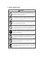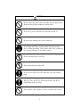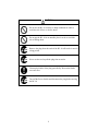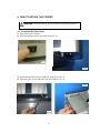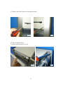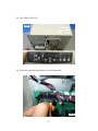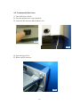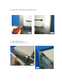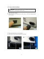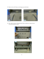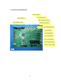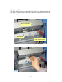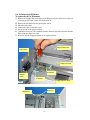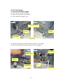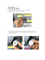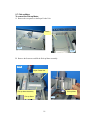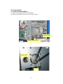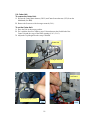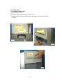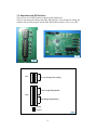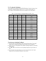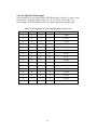
1
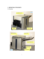
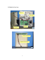
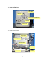
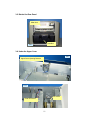
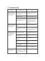
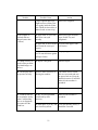
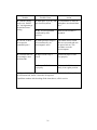
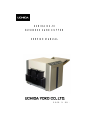
UCHIDA BC-10
BUSINESS CARD CUTTER
SERVICE MANUAL
CONTENTS
1. EXPLANATION OF SYMBOLS ··························································
3
2. SAFETY INSTRUCTIONS ···································································
4
3. DEFINITION OF THE PARTS ·····························································
7
3-1. Overview ··························································································
7
3-2. Behind the Front Cover ································································
8
3-3. Behind the Rear Cover ·································································
9
3-4. Behind the Front Panel ·································································
9
3-5. Behind the Rear Panel ·································································· 10
3-6. Under the Upper Cover ································································· 10
4. HOW TO DETACH THE COVERS ····················································· 11
4-1. To remove the Front Cover ·························································
11
4-2. To remove the Rear Cover ··························································· 14
4-3. To take off the Front Panel ··························································· 17
4-4. To take off the Rear Panel ···························································· 19
5. MAIN PARTS ························································································· 20
5-1. Pressure Roller Unit ······································································ 20
5-2. I/O Ports on the Mainboard ·························································· 21
5-3. Separate Pad ··················································································· 22
5-4. S1 Sensor and S2 Sensor ···························································· 23
5-5. DC Power Supply ··········································································· 24
5-6. Pick-up Roller ················································································· 25
5-7. Pick-up Motor ·················································································· 26
5-8. Stepping Motor ··············································································· 27
5-9. Cutter Unit ························································································ 28
5-10. Slitter Unit ······················································································ 29
2
6. TROUBLESHOOTING ········································································· 31
7. ADJUSTMENT ······················································································
35
7-1. To fix the paper skews ·································································· 35
7-2. Adjustment with DIP Switches ··················································· 37
7-2-1. To adjust the Top Margin ······················································ 38
7-2-2. To adjust the Card Length ···················································· 39
Please follow safety instructions on labels attached on the machine when you do service.
Be sure to turn off the Power Switch and remove the plug before touching the internal
parts of the machine.
1. EXPLANATION OF SYMBOLS
You will find following symbols in this Manual and on labels attached onto the
machine.
WARNING, which identifies a potentially hazardous situation which, if
not avoided, could result in death or injury.
CAUTION, which identifies a potentially hazardous situation which, if not
avoided, may result in minor or moderate injury or in property damage
incidents.
Prohibited
Do not
disassemble
Do not touch
with wet hands
Do not expose
to wet
conditions
Unplug
Need to
ground
General
instruction
Risk of electric
shock
3
2. SAFETY INSTRUCTIONS
WARNING
Connect the power cord directly into a wall-mounted outlet of
appropriate voltage. To avoid the risk of fires or electric shock, do
not connect to a multiple outlet strip.
Do not plug into an outlet of a voltage that is different from the
one marked on the serial tag. Operating on an incorrect voltage
can cause fires or electric shock.
Do not connect or disconnect the power cord with wet hands in
order to avoid electric shock or fires.
To avoid the risk of fires or electric shock, do not abuse the power
cord. Do not jput excessive weight on the cord, kpull without
holding the plug, lbend excessively, or mmodify the cord.
If a sheet is stuck in the Cutter Unit, jclear the error, kpress the
start button to open the cutter, and lturn off the Power Switch
before removing the paper.
Do not remove the transparent cover of the trash box. It is part of
the safety cover of the Slitter Unit, which keeps operator's hands
from being injured while the Card Stacking Box has been
removed.
Do not expose the BC-10 to rain or wet conditions in order to
avoid fires or electric shock.
If you notice a strange sound or smell while the BC-10 is running,
turn off the Power Switch immediately and remove the plug. Call
your supplier for repair.
4
CAUTION
Do not connect the power cord to an outlet when the plug is dusty.
Make sure the plug fits completely into the outlet.
Do not use a power cord that is not attached to the BC-10.
Do not use the attached power cord for other use.
To avoid the risk of fires or electric shock, do not operate the
BC-10 without grounding. If a three-hole outlet is not available, be
sure to ground the power cord with the adapter.
Do not disassemble the Cutter Unit.
Do not disassemble the Slitter Unit.
Be sure to turn off the Power Switch before removing jammed
paper.
When you move the BC-10, lift from the bottom. The BC-10
weighs about 46 lbs. (21.0kg).
Do not rub the edges of paper in order to avoid the risk of injury.
5
CAUTION
Do not use the BC-10 in dusty or damp conditions in order to
avoid the risk of fires or electric shock.
Do not put the BC-10 in an unstable place in order to avoid the
risk of falling down.
Remove the plug from the outlet if the BC-10 will not be in use for
a long period.
Never use the cord to pull the plug from an outlet.
Clean up the blades of the plug periodically. Dust on the blades
can cause fires.
Turn off the Power Switch and disconnect the plug before moving
the BC-10.
6
3. DEFINITION OF THE PARTS
3-1. Overview
3-1-1
Card Stacking Box
Trash Box
Front Cover
Operation Panel
Upper Cover
Paper Feeder Unit
Power Inlet
Power Switch
3-1-2
7
3-2. Behind the Front Cover
Cutter Unit
Left Frame
Mainboard
Front Cover
3-2-1
Operation Panel PCB
Operation Panel Harness
3-2-2
8
3-3. Behind the Rear Cover
Right Frame
Cutter Unit
Pulley to drive Conveying Rollers
Timing Belt
Stepping Motor
3-3-1
3-4. Behind the Front Panel
3-4-1
Stepping Motor
Trash Box Detector
DC Power Supply
Power Inlet
Power Switch
Front Panel
9
3-5. Behind the Rear Panel
Slitter Unit
Trash Box
3-5-1
3-6. Under the Upper Cover
3-6-1
Upper Cover Opening Detector
3-7-1
S3 Sensor
Cutter Unit Cover
10
4. HOW TO DETACH THE COVERS
WARNING: Be sure to turn the power off before removing any panel or
cover.
4-1. To remove the Front Cover:
1. Turn off the Power Switch.
2. Move the machine to the verge of the desk (4-1-2).
4-1-1
4-1-2
3. Loosen the two M3 Setscrews under the Front Cover (4-1-3).
4. Open the Upper Cover and remove the M3 Setscrew (4-1-4).
4-1-4
4-1-3
11
5. Remove the two M3 Setscrews from the Rear Panel.
4-1-5
4-1-6
6. Take off the Rear Panel.
7. Remove the M3 Setscrew (4-1-8).
4-1-7
12
4-1-8
8. Take off the Front Cover.
4-1-9
9. Pull out the Operation Panel harness from the Mainboard.
4-1-10
13
4-2. To remove the Rear Cover:
1. Turn off the Power Switch.
2. Move the machine to the verge of the desk.
3. Loosen the M3 Setscrews under the Rear Cover.
4-2-1
4-2-2
4. Open the Upper Cover.
5. Remove the M3 Setscrew.
4-2-3
14
6. Remove the two M3 Setscrews from the Rear Panel.
4-2-4
4-2-5
7. Take off the Rear Panel.
8. Remove the M3 Setscrew (4-2-7).
4-2-6
4-2-7
15
9. Take off the Rear Cover. There is no harness behind the Rear Cover.
4-2-8
16
4-3. To take off the Front Panel:
WARNING: Be sure to pull out the Power Cord before removing the Front
Panel in order to avoid the risk of electric shock.
1. Turn off the Power Switch.
2. Pull out the Power Cord from the Power Inlet. There is a DC Power Supply behind
the Front Panel.
4-3-1
4-3-2
3. Move the machine to the verge of the desk.
4. Remove the two M3 Setscrews under the Front Panel.
4-3-3
4-3-4
17
5. Remove the two M3 Setscrews in the upper part of the Panel.
4-3-5
4-3-6
6. Take off the Front Panel. Behind the Panel, there are harnesses connected to the
Power Inlet and Power Switch.
4-3-7
4-3-8
18
4-4. To take off the Rear Panel:
1. Turn off the Power Switch.
4-4-1
2. Remove the two M3 Setscrews from the Rear Panel.
4-4-2
4-4-3
3. Take off the Rear Panel.
4-4-4
19
5. MAIN PARTS
5-1. Pressure Roller Unit
To remove the Pressure Roller Unit:
1. Open the Upper Cover.
2. Lift the handle.
Upper Cover
Pressure Roller Unit
5-1-1
5-1-2
20
5-2. I/O Ports on the Mainboard
CN2: S3 Sensor
CN3: Cutter Sensor
CN1: S2 Sensor
CN4: Trash Box Detector
CN9: Operation Panel
CN5: Slitter Detectors
CN6: Upper Cover Opening Detector
CN7: S1 Sensor
CN13: Slitter Motor
CN12: Cutter Motor
CN11: Pick-up Motor
CN10: Stepping Motor
CN8: DC Power Supply
5-2-1
21
5-3. Separate Pad
The Paper Feeder Unit can be swung only 30° for safety’s sake. When you replace the
pad, insert a screwdriver between the Paper Feeder Unit and Paper Induction Deck to
keep the Paper Feeder Unit open.
Paper Feeder Unit
Separate Pad
Paper Induction Deck
5-3-1
5-3-2
22
5-4. S1 Sensor and S2 Sensor
To replace the S1 or S2 sensor:
1. Remove the Stopper Pin located next to the Hinge Pin on the left frame so that you
can swing up the Paper Feeder Unit wider than 30°.
2. Remove the M2 Setscrews and pick up the sensor.
3. Disconnect the cable.
4. Connect the cable to the new sensor.
5. Set the Sensor in the proper position.
6. Tighten the Setscrews. The standard clearance between the Sensor Bracket and the
Paper Induction Deck is 0.6mm
7. Be sure to put the Stopper Pin back to its regular position.
Paper Feeder Unit
Left Frame
Cutter Unit Cover
S2 Sensor
Magnet
Catch
S1 Sensor
Paper Induction Deck
5-4-1
Hinge Pin
Stopper Pin
5-4-2
23
5-5. DC Power Supply
To remove the DC Power Supply:
1. Take off the Front Panel (See 4-3).
2. Remove the Setscrews on both frames.
3. Take off the Power Supply Cover.
5-5-1
5-5-2
Power Supply Cover
Setscrew
Setscrew
Power Switch
Front Panel
4. Disconnect the Input and Output Cable from the DC Power Supply.
5. Remove the M3 Setscrews and pick up the DC Power Supply.
5-5-3
5-5-4
Input Cable
Output Cable
Setscrew
Fuse
Power Supply
Power Inlet
24
5-6. Pick-up Roller
To replace the Pick-up Roller:
1. Swing up the Paper Feeder Unit.
2. Keep the Paper Feeder Unit open with a screwdriver (See 5-3).
3. Remove the Setscrew and pull out the Roller.
5-6-1
Paper Feeder Unit
Setscrew
Pick-up Roller
4. Put a new Roller on the shaft. The Roller has a one-way clutch, so that it does not
rotate in the wrong direction. Make sure the clutch side faces the Setscrew (5-6-2).
5. Tighten the Setscrew.
5-6-2
5-6-3
One-way Clutch
Reverse side
25
5-7. Pick-up Motor
To remove the Pick-up Motor:
1. Remove the two panels on the Paper Feeder Unit.
Panels
5-7-1
5-7-2
2. Remove the Setscrews and lift the Pick-up Motor assembly.
5-7-3
Paper Feeder Unit
Pick-up Motor Assembly
Pick-up Motor
Pick-up Roller
5-7-4
26
5-8. Stepping Motor
To remove the Stepping Motor:
1. Disconnect the harness from the Main Board.
2. Remove the M4 Nuts. Take care not to drop the motor.
Stepping Motor
5-8-1
Stepping Motor harness
5-8-2
Stepping Motor
M4 Nuts
27
5-9. Cutter Unit
To remove the Cutter Unit:
1. Pull out the Cutter Motor harness (CN12) and Cutter Sensor harness (CN3) from the
Mainboard (See 5-2).
2. Remove the Setscrews with a hexagon wrench (5-9-1).
To set the Cutter Unit:
1. Place the Unit in the proper position.
2. Fix it with the Setscrews. Make a gap of 1.0mm between the fixed blade of the
Cutter Unit and the verge of the frame openings (5-9-2, 5-9-3).
3. Adjust the Top Margin after the setup is finished.
Cutter Unit
Right Frame
Hexagon Wrench
5-9-1
Left Frame
Thickness gauge (1mm)
5-9-2
28
5-9-3
5-10. Slitter Unit
To remove the Slitter Unit:
1. Open the Upper Cover.
2. Remove the M4 Setscrews from the Slitter Unit.
3. Remove the M3 Setscrews from the Rear Panel and take off the Panel from the
machine.
Upper Cover
Setscrews
Setscrews
5-10-1
5-10-2
Rear Panel
5-10-3
29
4. Pull out the Slitter Motor harness from the Connector.
Harness Connector
Slitter Unit
5-10-4
5-10-5
5. Hold the both sides of the Slitter Unit and swing up to remove it.
5-10-6
5-10-8
30
5-10-7
6. TROUBLESHOOTING
Troubles
1. The Display and
LEDs do not light up
when you turn on the
Power Switch.*
Possible Cause
Action
Connect the Power Cord
The Power Cord is not
properly connected to an outlet properly to an outlet and the
Power Inlet.
and the Power Inlet.
The Outlet is dead.
Make sure the outlet is alive.
An excessive electromagnetic
wave or static electricity is
affecting the machine.
Turn the power off and move
the machine away from the
possible source. Turn the
power back on after seven
seconds.
2. The BC-10 does not There is an error code in the
work when you press Display.
the Start button.*
The "Preset" number is set to
"0" with the "Preset" mode
being on.
Clear the error and restart.
3. The BC-10 does not The sheets are too thick.
start feeding sheets
when you press the
The lead edge of the sheets
Start button.*
curls too much.
Try thinner sheets (under 0.01"
or 0.25mm).
There is some silicone oil on
the sheets.
For a test cutting, select "10"
as the "Preset" number and try
cutting again. Refer to 6.8.
Straighten the lead edge of the
sheets.
Replace the sheets.
The friction of the paper is too Try some other paper with less
much.
friction.
The Pick-up Roller has worn
out to lose its grip.
Replace the Pick-up Roller.
The Separate Pad is worn out. Replace the Separate Pad.
4. A sheet stops after
moving slightly.
The sensor cannot detect
because the paper is irregular
(highly transparent or too
dark).
31
Use proper papers.
Troubles
Possible Cause
Action
You are trying to cut sheets
without a Cutting Mark while
the Cutting Mark function is
on.
Turn off the Cutting Mark
function or use the sheets with
a Cutting Mark.
The Cutting Mark is printed
with a dye-based inkjet printer,
so that the Sensor cannot
detect the Mark.
Trace the Cutting Mark with a
dark-colored pencil or marker
or print with a laser printer or
pigment-based inkjet.
Since the Paper Feeder Tray is Reset the Paper Feeder Tray
properly.
skewed, the sensor cannot
detect a sheet.
5. Two or more sheets
are fed at one time.
The humidity of the
atmosphere is so low as to
cause electrostatic problems.
Operate the BC-10 under
proper conditions. Keep the
humidity between 50 and 80%.
The sheets get stuck together
because of static electricity.
Fan the stack of sheets and
reload.
The BC-10 is not grounded.
Make sure the machine is
grounded.
The Separate Pad is worn out. Replace the Separate Pad.
6. The BC-10 stops in
the middle of cutting
and “E002” appears in
the Display
(repeatedly).
The Cutter blades have got
damaged and got partly dull
because something hard such
as a clip or a staple was cut.
Replace the Cutter Unit.
7. The cut edges are
not crisp.
The Cutter blades have worn
out. (When the long sides of
finished cards are not crisp.)
Replace the Cutter Unit.
The Slitter discs have worn
out. (When the short sides of
finished cards are not crisp.)
Replace the Slitter Unit.
32
Troubles
Possible Cause
Action
Remove the fragment.
A paper fragment has been
caught between a Slitter Disc
and a spring inside the Slitter
Unit. (When the short sides of
finished cards are not crisp.)
8. The lengths of
finished cards are
unequal (more than
0.15mm).
The paper curls or waves too
much to be conveyed
smoothly.
Remove the paper from the
Paper Feeder Tray and
straighten it.
The paper has so much friction Try some other papers with
less friction.
that it cannot be conveyed
properly.
Use proper papers.
The paper is so wide as to
have too much friction against
the Paper Guides.
9. Cutting accuracy is The layout is not good.
good, but the positions
of printed images are
uneven.
Redo the layout.
10. The Display does
not operate correctly.
Excessive static electricity is
affecting the machine.
Turn off the Power Switch.
Wait seven seconds and turn
the power back on. Keep the
humidity between 50 and 80%.
Make sure the machine is
grounded.
The BC-10 is out of order.
Call for service.
The BC-10 is not grounded
and affected by static
electricity.
Make sure the machine is
grounded.
11. Finished cards do
not accumulate neatly
in the Card Stacking
Box or cut fragments
get scattered in the
Trash box.
The atmosphere is too dry and Check the humidity and try a
static electricity affects.
humidifier if needed.
33
Troubles
Possible Cause
Action
12. With the cutting
mode set to “double
cut,” cut fragments go
forward and cause
fouling.
The atmosphere is too dry and Try a humidifier to make the
static electricity affects.
atmosphere more humid than
50%.
The BC-10 is not grounded
and affected by static
electricity.
Make sure the machine is
grounded.
13. The BC-10 does
not respond to
command inputs.*
The Onboard Microcomputer
has been affected by an
electromagnetic noise.
Turn off the Power Switch.
Wait seven seconds and turn
the power back on. This
procedure resets the
microcomputer.
14. Finished cards are
not rectangles, more
like diamonds.
The Paper Feeder Tray is
skewed.
Reattach the Paper Feeder
Tray properly.
The Pressure Roller Unit is not Make sure the Unit is set
set properly.
neatly in its regular position.
*1, 2, 3, and 13: If all of the items in each section have been checked and the problems
are still unresolved, the BC-10 needs to be repaired.
If problems continue after checking all the items above, call for service.
34
7. ADJUSTMENT
7-1. To fix the paper skews:
1. Make sure the Paper Feeder Tray is set properly.
Hopper Plate
Left Paper Guide
Right Paper Guide
7-1-1
2. While holding the M3 Nut under the Paper Feeder Tray, loosen the Left Paper Guide
Adjusting Screw.
3. Move the Left Paper Guide slightly to fix the paper skew.
4. Tighten the Screw.
Paper Feeder Tray
(Reverse side)
Left Paper Guide
Adjusting Screw
M3 Nut
7-1-2
35
7-1-3
If the above procedure does not work, loosen the Setscrews of the Pick-up Motor
Assembly and adjust the alignment.
7-1-4
Paper Feeder Unit
Pick-up Motor Assembly
Pick-up Roller
36
7-2. Adjustment with DIP Switches
There are two sets of DIP Switches in the left of the Mainboard.
Note: Do not change the setting of the SW1 DIP Switches. If you change the setting, the
machine will not work properly. All the SW1 DIP Switches must be set to “0 (or Off).”
7-2-2
7-2-1
1
SW1
2
3
Do not change the setting.
4
1
2
3
Card Length Adjustment
4
SW2
5
6
7
Top Margin Adjustment
8
: 1 (ON)
: 0 (OFF)
7-2-3
37
7-2-1. To adjust the Top Margin:
You can adjust the Top Margin with the SW2 DIP Switches. You have 16 steps (1 step:
0.125mm) by setting four toggle switches (#5, #6, #7 and #8). See the table 7-A.
Note: Changes of the DIP Switches affect the Top Margins of all Cutting Modes.
Table 7-A: Switch settings for Top Margin Adjustment (0=Off, 1=On)
#5
#6
#7
#8
Adjusting amount (mm)
0
0
0
0
-1.000
1
0
0
0
-0.875
0
1
0
0
-0.750
1
1
0
0
-0.625
0
0
1
0
-0.500
1
0
1
0
-0.375
0
1
1
0
-0.250
1
1
1
0
-0.125
0
0
0
1
±0.000
1
0
0
1
+0.125
0
1
0
1
+0.250
1
1
0
1
+0.375
0
0
1
1
+0.500
1
0
1
1
+0.625
0
1
1
1
+0.750
1
1
1
1
+0.875
*The other way of adjusting Top Margin:
1. Press the Adjust Top margin button on the Operation Panel and the “Top margin”
LED will turn on and the Top Margin value used in the last job will appear.
2. When you browse Cutting Modes, the standard Top Margin length for each Cutting
Mode appears.
3. Press p or q to increase/decrease the Top Margin length one step (0.25mm) at a
time.
4. Press the Adjust Top margin button to save the value and return to the Counter
Display. Refer to the Operation Manual for more details.
38
7-2-2. To adjust the Card Length:
You can adjust the Card Length with the SW2 DIP Switches. You have 16 steps (1 step:
0.125mm) by setting four toggle switches (#1, #2, #3 and #4). See the table 7-B.
Note: Changes of the DIP Switches affect the Card Lengths of all Cutting Modes.
Table 7-B: Switch settings for Card Length Adjustment (0=Off, 1=On)
#1
#2
#3
#4
Adjusting amount (mm)
0
0
0
0
-1.000
1
0
0
0
-0.875
0
1
0
0
-0.750
1
1
0
0
-0.625
0
0
1
0
-0.500
1
0
1
0
-0.375
0
1
1
0
-0.250
1
1
1
0
-0.125
0
0
0
1
±0.000
1
0
0
1
+0.125
0
1
0
1
+0.250
1
1
0
1
+0.375
0
0
1
1
+0.500
1
0
1
1
+0.625
0
1
1
1
+0.750
1
1
1
1
+0.875
39