1
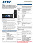
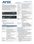
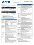
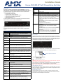
Installation Guide
Enova AVX-400-SP Cat5 Presentation Switcher
Overview
Enova AVX-400-SP Cat5 Presentation Switcher Specifications (Cont.)
The Enova AVX-400-SP Cat5 Presentation Switcher (FG1350-01) is a four input,
multi-format active presentation switcher with auxiliary line level audio input. The
AVX-400-SP (FIG. 1) is a Cat5 switcher with basic projector/display control via RS-232,
but with external control of the switcher via RS-232 or AxLink. This presentation
switcher incorporates the following:
• External serial or AxLink control
• Projector or display control via RS-232
• Integrated multi-format Cat5 audio/video switcher
• Audio mixer with an auxiliary line input facility
• Audio volume and tone control
• Built-in audio amplifier
For more information, consult the Enova AVX-400-SP Cat5 Presentation Switcher
Operation/Reference Guide available at www.amx.com.
Dimensions
(HWD):
Weight:
2.57 lbs (1.17 kg)
Certifications:
FCC Class B, CE, and IEC60950
Included
Accessories:
•
•
•
•
•
Optional
Accessories:
• UPX-CN+A Component Universal Transmitter Wallplate
(FG1402-52)
• UPX-CS+A Composite Universal Transmitter Wallplate
(FG1402-50)
• UPX-RGB+A RGB Universal Transmitter Wallplate (FG1402-51)
• Surface Mount Kit (KA2250-40) with mounting bracket
(62-2254-02)
• SP-08-AX 8-Button Keypad with AxLink (FG1311-08)
• CC-HD15 Male to HD-15 Male cable (FG10-2170-01)
FIG. 1 Enova AVX-400-SP Cat5 Presentation Switcher (front panel)
The following table lists the specifications for the AVX-400-SP Cat5 presentation
switcher:
Enova AVX-400-SP Cat5 Presentation Switcher Specifications
Power:
1.75" (4.45cm) x 9" (22.86cm) x 6" (15.24cm) HWD
12VDC, 4.4A supply
2 5-pin 3.5mm Phoenix connectors, for line-in/out (41-0336)
1 4-pin 3.5mm Phoenix connector, for AxLink (41-5047)
2 2-pin 5 mm Phoenix connectors, for speakers (41-0158-SA)
1 RS-232 3-pin 3.5mm Phoenix connector (41-0338)
1 PSN4.4, Power Supply, 4.4A, 3.5mm Phoenix, 13.5VDCA5
(FG423-45)
• Enova AVX-400-SP Cat5 Presentation Switcher Installation
Guide (93-1350-01)
• 1 Suppression Ferrite (04-0018-SA)
Audio Amplifier: Stereo 10W per channel with 7-band graphic equalization
Wiring and Connections
Enclosure:
Source Inputs
Metal with black matte finish
Front Panel Components:
Source Select
Button
1 button for toggling through the 4 inputs with each press
Source Select
LED Indicators
4 LED indicators which show which source has been selected
Source Inputs
(INPUTS 1-4)
4 RJ-45 connectors for source audio and video
LINE IN
Auxiliary Audio
Input
1 3.5mm Phoenix (5-pin) connector for use with external audio
equipment such as radio microphones and mixers.
AxLink DEVICE
DIP Switches
1 set of 8 DIP switches for setting the address of an AxLink device
AxLink Port
1 3.5mm Phoenix (4-pin) connector that provides data to external
control devices and allows the AVX-400-SP to be controlled from
a Master. A green AxLink LED indicates the state of the AxLink
port.
RS-232 Control
Port
1 3.5mm Phoenix (3-pin) connector that provides data to external
control devices
Configuration
Port (PROG)
1 type-B USB connector for configuring the switcher via AMX DCS
software
Power
Connector
1 3.5mm Phoenix (2-pin) connector
The Source inputs (FIG. 2) can accept video from devices such as PCs, DVD players,
satellite receivers, and video conference systems via Cat5 wallplates. You can use the
Source Input ports to connect RJ-45 cables to the port on a wall input plate which then
connects to an input device via composite, component, or RGB/VGA connector. The
LED beside each port lights red when its associated port is active.
FIG. 2 Front panel source inputs
When connecting to a wall input plate, use Cat5/5e/6 cable to connect from the source
input on the switcher to the RJ-45 connector on the wall input plate (FIG. 3).
Wall input plate RJ-45 connector
FIG. 3 Wall input plate RJ-45 connector
Rear Panel Components:
RS-232 Display
Control
1 male DB9 connector used to control a projector or display from
the AVX-400-SP
Audio Amplifier
Output
1 5.0mm Phoenix (4-pin) connector capable of delivering 2x10W
into 8 ohm variable stereo audio amplifier.
Line Level
Audio Output
1 3.5mm Phoenix (5-pin) connector provides the mixed audio at
Line Level
Composite
Output
1 RCA (Y) connector for connecting to a display device
VGA/RGB
Output
1 HD-15 connector for connecting to a display device.
Component
Output
1 HD-15 connector for connecting to a display device. You can
use breakout cable CC-HD15M-RCA3M (FG10-2170-03) to
connect to 3 x RCA Phono Sockets.
Operating
Environment:
Storage Temperature: -10º C to 70º C (14º F to 158º F)
Operating Temperature: 0º C to 40º C (32º F to 104º F)
Operating Relative Humidity: 5% to 85% non-condensing
Warning: DO NOT use Cat5 crossover cable for source input connections. Using Cat5
crossover cable may damage the presentation switcher.
Once connected, you can activate the connected source input by pressing the button on
the front of the wall input plate. See Switching Mode for more information.
NOTE: Extended Display Identification Data (EDID) is not passed by the AVX-400-SP.
HD-15 Output Connectors
Each AVX-400-SP has two HD-15 output connectors. The outputs enable you to use an
HD-15 to Component or standard VGA cable to send video to a display device such as
a projector or large screen monitor.
RS-232 Display Control
The RS-232 display control connector is used for controlling the switcher from an
RS-232 device such as a projector or large screen LCD. FIG. 4 shows the connector
pinouts for the rear RS-232 display control connector.
1 2 3 4 5
RS-232 pinouts (male connector)
Pin 2: RX signal
Pin 3: TX signal
Pin 5: GND
6 7
8 9
FIG. 4 RS-232 DB9 (male) connector pinouts for the rear Display Control connector
AxLink Port
All AVX-400-SP units have an AxLink port and adjacent status LED. This port allows the
unit to be controlled from any AxLink Master such as a NetLinx Integrated Controller. A
green LED shows AxLink data activity.
Note: The AVX-400-SP cannot be powered by this port or used to power other devices.
AxLink DEVICE DIP Switches
The 8-position AxLink DEVICE DIP switch sets the AxLink identification number for
your AxLink device. Consult the Enova AVX-400-SP Cat5 Presentation Switcher
Operation/Reference Guide for information on DIP switch settings.
Configuration Port
FIG. 7 AMX DCS window
FIG. 5 Configuration port (PROG)
The AVX-400-SP contains one low-speed type-B USB connector (labelled PROG)
located on the front of the unit. Use a standard USB cable to establish a connection
between the device and your PC's USB port. This connection enables you to program
the switcher by using AMX DCS software.
Warning: Install the DCS software on your PC before connecting a USB cable between
the PC and AVX-400-SP. Failing to do so may cause an installation error.
FIG. 8 AMX DCS window - Display tab
Power Connector
The AVX-400-SP uses a 12 VDC-compliant power supply to provide power to the
switcher through the front 2-pin 3.5 mm mini-Phoenix power connector.
Warning: This unit should only have one source of incoming power. Using more than
one source of power to the Controller can result in damage to the internal components
and a possible burn out. Apply power to the unit only after installation is complete.
Supression Ferrite Installation
If you are in a location with 240V of power, you must clip the supplied Suppression
Ferrite around the power cable (no tools required).
1
2
3
(complete)
FIG. 6 Installing the Suppression Ferrite
1.
Release the latch to open the plastic enclosure.
2.
Insert the power cable and close the enclosure.
AMX DCS Software
You can configure the AVX-400-SP and its functionality by using AMX DCS software.
The top of the window displays the device image of the front panel of the Enova
AVX-400-SP, and displays which inputs are valid by highlighting the source input.
Clicking on a highlighted port on the device image changes the active input. The active
source input is indicated by the illuminated red LED beside the source input. The
bottom half of the window features the Device Setup options (FIG. 7).
Enabling Display Control
Display control enables you to select a display to use for the output from your source
inputs. A display can be any type of video output device. After enabling display control,
you can select a make, type, and model of display. If your display is not available from
the options menus, see the Device Library Manager section in the Enova AVX-400-SP
Cat5 Presentation Switcher Operation/Reference Guide for information on adding your
specific device to the device library.
Perform these steps to enable display control:
1.
Click the Display tab on the AMX DCS window (FIG. 8).
2.
Click the Enabled check box to enable display control.
3.
Select a Make, Type, and Model display from their respective fields.
4.
Click Program Device to send the display device’s commands to the
presentation switcher.
Switching Mode
Setting the switching mode enables you to control how a source input is activated. You
can choose from Take-over mode, Toggle mode, and priority switching. Take-over mode
enables you to activate a source input by pressing the button on the corresponding wall
input plate. With toggle mode, if you press the button on any of the wall plates, then the
selected video input changes to the next available input.
Priority Switching
Priority switching enables you to establish a priority order for displaying each input
device. The input device with the highest priority will always be sent to the output
display as long as the input device remains powered on. When the power to the highest
priority input device is turned off, the signal from the next active input device appears on
the output display.
For example, you have a DVD player set at priority 1, a PC at priority 2, and a VCR at
priority 3. If the PC is always powered on, it’s output is sent to the display provided the
DVD player is currently powered off. When the DVD player is powered on, its output is
immediately sent to the display. Powering off the DVD player returns the PC’s output to
the display. The VCR’s output is only sent to the display if it is powered on, and the DVD
player and PC are both powered off.
Perform these steps to set up priority switching:
1.
In the Device Setup area, click the Display tab.
2.
Click the Priority Switching option button in the Switching Mode section.
3.
Use the options menus in the Priority Switching area to indicate the priority order
for each input device. The number you select from the drop-down menu is the
source input number on the presentation switcher. For example, if you want
source input 3 to have the highest priority, select 3 from the first menu.
4.
Click Program Device to send the new settings to the presentation switcher.
Updating Firmware
AMX DCS software provides a simple interface for updating your AVX-400-SP with the
latest available version of firmware. You must use a .bin file to upgrade the firmware
through AMX DCS software. The latest firmware files can be found at the Tech Center
at www.amx.com.
Perform these steps to update the firmware for your device:
1.
From the File menu, select Enova Firmware Update. The Enova Firmware
Update window opens.
2.
Click Go to AMX.com. A web browser opens and navigates to www.amx.com.
3.
Click Tech Center on the main page at AMX.com.
4.
Locate and download the latest firmware version (.bin) for your device. Make note
of the location to which you save the firmware file. When the download is
complete, return to the Enova Firmware update window.
5.
Click Select File, navigate to the location the firmware file was saved, and select
the file.
6.
Click Update. The firmware for the device is updated with the latest version.
7.
Click Close to close the window and return to the AMX DCS window.
For full warranty information, refer to the AMX Instruction Manual(s) associated with your Product(s).
4/11
©2011 AMX. All rights reserved. AMX and the AMX logo are registered trademarks of AMX.
AMX reserves the right to alter specifications without notice at any time.
3000 RESEARCH DRIVE, RICHARDSON, TX 75082 • 800.222.0193 • fax 469.624.7153 • technical support 800.932.6993 • www.amx.com
93-1350-01
REV: C