1
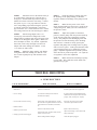
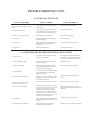
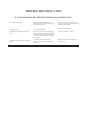
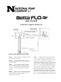
JET PUMP
INSTALLATION MANUAL
SHALLOW WELL JET PUMPS
STEP 1
Make sure the well is pumped clean and
that sand and grit are absent.
STEP 2
Before installing a shallow well or
centrifugal pump make sure the total suction lift does
not exceed 25 feet.
STEP 3
For convertible jet pumps attach the
ejector to the pump housing, making sure that the
1 1/4” and 1” tapped holes in the ejector match up
with the 1 1/4” and 1” tapped holes in the pump
housing.
STEP 4
Install a 1 1/4” foot valve on the bottom
of the suction pipe, on driven wells, where the well
casing is used as suction pipe, install a 1 1/4”
horizonal line check valve.
STEP 5
Install a sanitary well seal onto the top
of the 1 1/4” suction pipe to fit well diameter. Use
1 1/4” tee and a 1 1/4” plug at the top of the well seal
to support suction pipe in the well. Install 1 1/4”
union between well and 1” pressure pipe that will rest
on the well seal to support the pipes and ejector or jet
in well. A 1 1/4” tee or elbow can be used on the top
of the 1 1/4” suction pipe which needs to be slightly
higher than the 1” pressure pipe to make the connection to the pump housing. Install a compression
coupling on both suction & pressure pipes staggering
them apart from each other. Install 1 1/4” pipe into
the 1 1/4” tap in the pump housing. Install 1” pipe in
to the 1” tap in the pump housing. Join together with
SHALLOW WELL JET PUMPS
CONT.
two unions between the pump and the well. If
vertical pump is being used, adapt the 1 1/4” and 1”
pipes directly into the 1 1/4” and 1” taps in the pump
housing and adapt some type of supports or legs from
the foundation to brackets on the pump housing to
support the weight of the pipes, ejector or jet in the
well.
STEP 6
Prime pump by pouring water into the
discharge of the pump housing or automatic regulator
that is mounted on the discharge of pump.
STEP 7
Make sure pump is off! Check motor
decal and make sure motor is wired for voltage being
used. Make your wire connections in the pressure
switch.
STEP 8
Adjust regulator to maximum pressure,
and start the pump. When pressure builds up on the
pressure guage, start opening regulator slowly. The
pump will start discharging water and the pressure
will decrease. Continue to slowly open up regulator
until pump starts to charge tones or pump starts to
lose prime. At this point determine what your
operating pressure is by the reading on the pressure
guage. Adjust regulator back up about 5 pounds
above this tone or prime loss pressure. Put a jam nut
on regulator to secure adjustment.
STEP 9
Make connection on the discharge of
pump to the water tank. This connection can be
made with galvanized or pvc pipe.
DEEP WELL JET PUMP
DOUBLE PIPE
STEP 1
Make sure the well is pumped clean and
that sand and grit are absent.
STEP 2
Deep well pumps are always installed
with the ejector or jet attached to the bottom of the
suction and pressure pipe in the well. A foot valve
must be used if the ejector does not have a built in
check valve. A tail pipe may be used beneath the
ejector with the foot valve at the bottom of the tail
pipe.
STEP 3
Connect foot valve to bottom of jet with
1 1/4” galvanized nipple or full length of 1 1/4”
galvanized pipe. Connect 1 1/4” galvanized pipe to
1 1/4” tap in ejector or jet body. Connect 1” pipe to
the 1” tap in ejector or jet body. Keep adding pipes
until you reach the desired depth. As each pipe is
added fill each with water after lowering in well.
STEP 4
Install a double pipe sanitary well seal
at the top of the well to keep out contamination and
to support the pipe and ejector or jet in well.
STEP 5
Use 1” galvanized elbow on top of
pump. Connect suction pipe into tapped hole in
housing or ejector. Pump needs to be installed at an
uphill slope from the well with no dips or low spots
to eliminate the possibility of air pockets. Pump
needs to be mounted onto the foundation for
smoother and quieter operation and prolonged motor
life.
STEP 6
Prime the pump! Be sure the suction
pipe and pump housing are full of water with no
trapped air pocket in suction line.
STEP 7
Make sure power is off! Check motor
decal and make sure motor is wired for voltage being
used. Connect power voltage wire to terminals
marked line voltage in pressure switch. Connect
ground wire to ground terminal on pressure switch.
STEP 8
Start pump! If pressure does not build
after a reasonable time, stop the pump. Reprime and
start again. Allow pump to operate briefly to purge
air from the system. This procedure may have to be
repeated until pump builds up pressure.
STEP 9
Make connection on discharge of pump
to water tank. This connection can be made with
galvanized or pvc pipe.
DEEP WELL JET PUMP
SINGLE PIPE
STEP 1
Make sure the well is pumped clean and
that sand and grit are absent.
STEP 2
Deep well pumps are always installed
with the ejectors or jet attached to the bottom of the
suction pipe in the well. A foot valve must be used if
the ejector or jet does not have a built in check valve.
A tail pipe may be used beneath the ejector or jet with
the foot valve mounted on the bottom of the tail pipe.
STEP 3
Install foot valve to the bottom of the jet
or on the bottom of the tail pipe, if the tail pipe is
being used. Stretch leather cup washer to open up
leathers for a better seal in the well casing. Connect
the ejector or jet to 1 1/4” pipe and lower into the
well. Keep adding pipes and lowering the ejector or
jet into the well to the desired depth. Fill suction
pipe with water as it is lowered into the well. Fill the
well casing with water as each suction pipe is added.
STEP 4
Install casing adapter onto 1 1/4”
suction pipe, lossen the three flange bolts on the
adapter and lower adapter onto the well casing, being
careful not to damage the rubber gasket. Make sure
the well adapter is all the way around. Tighten the
three bolts, each evenly until tight. Fill the well
adapter with water making sure both the 1” and
1 1/4” holes are full of water.
STEP 5
Mount the pump onto the well adapter
with gaskets and bolts, making sure that the 1 1/4”
and 1” holes in pump line up with the holes in the
adapter.
STEP 6
Prime the pump by pouring water into
the discharge of the pump housing or automatic
regulator mounted in discharge of the pump on some
models.
STEP 7
Make sure the power is off! Check
motor decal and make sure the motor is wired for the
voltage being used. Make your wire connections in
the pressure switch.
STEP 8
Adjust the regulator to maximum
pressure, start the pump when the pressure builds up
on the pressure guage start opening the regulator
slowly. The pump will start discharging water and
the pressure will start decreasing as the discharge
flow increases. Continue to slowly open up the
regulator until pump starts to change tones or pump
starts to loose its prime. At this point determine what
your operating pressure is by reading the pressure
guage. Adjust the regulator back up about 5 pounds
above this tone or prime lost pressure. Use a jam nut
on regulator to secure this adjustment.
STEP 9
Make connection on discharge of pump
to water tank. This connection can be made with
galvanized or pvc pipe.
TROUBLE SHOOTING
A. PUMP WON’T RUN
CAUSE OF TROUBLE
HOW TO CHECK
HOW TO CORRECT
1. Blown fuse.
Check to see if fuse is ok
If blown, replace with fuse of proper size.
2. Low in voltage
Use voltmeter to check pressure switch or
terminals nearest pump
If voltage is under recommended minimum,
check the size of wiring from main switch on
property. If ok, contact power company.
3. Loose, broken or incorrect wiring.
Check wiring circuit against diagram. See that
all connections are tight and that no short circuits
exist because of worn insulation, crossed wire,
etc.
Rewire any incorrect circuits. Tighten
connections, replace defective wires.
Check to see that switch is closed
Repair or take to motor shop.
Check switch setting. Examine switch contacts
for dirt or excessive wear.
Adjust switch settings. Clean contacts with
emory cloth if dirty.
Remove tubing and blow through it.
Clean and replace if plugged.
4. Defective Motor
5. Defective pressure switch
6. Tubing to pressure switch clogged
TROUBLE SHOOTING CONT.
A. PUMP WON’T RUN CONT..
CAUSE OF TROUBLE
HOW TO CHECK
HOW TO CORRECT
7. Impeller or seal
Turn off power, then use screwdriver to turn
impeller or motor.
If impeller won’t turn, remove turn housing
and locate source of binding.
8. Defective start capacitor
Use an omhmmeter to check resistance across
capacitor. Needle should jump when contact
is made. No movement means an open
capacitor, no resistance means capacitor is
shorted.
Replace capacitor or take motor to a service
station.
9. Motor shorted out
If fuse blows when pump is started ( and
external wiring is ok) motor is shorted.
Replace Motor
B. MOTOR OVERHEATS AND OVERLOAD TRIPS OUT
Use voltmeter to check at pressure switch or
terminals nearest pump
If voltage under recommended minimum,
check size of wiring from main switch on
property. If ok, contact power company.
2. Motor wired incorrectly
Check motor wiring diagram
Reconnect for proper voltage as per wiring
diagram.
3. inadequate ventilation
Check air temperature where pump is located.
Iif over 100 degrees F overload may be
tripped out on external head
Provide adequate ventilation or move pump.
4. Prolonged low pressure delivery
Continuous operation at very low pressure
places heavy overload on pump. This can
cause overload protection to trip.
. 1. Incorrect line voltage
Install globe valve on dicharge line and
throttle to increase pressure
C. PUMP STARTS AND STOPS TOO OFTEN
1. Leak in the pressure tank
Apply soapy water to entire surface above
water line. If bubbles appear, air is leaking
from the tank.
Repair leaks or repair tank.
2. Defective air volume control
This will lead to a waterlogged tank. Make
sure control is operating properly. If not,
remove and examine for plugging.
Adjust switch settings. Clean with emory
cloth if dirty.
3. Leak on discharge side of system
Make sure all fixtures in plumbing system are
shut off. Then check all units (especially
ballcocks) for leaks. Listen for noise of water
running.
Repair leaks as necessary.
4. Leak on suction side of system
On shallow well units, install pressure guage
on suction side. On deep well systems, attach
a pressure guage to the pump. Close the
discharge line valve. Then using a bicycle
pump or air compressor, apply about 30 psi
pressure to the system. If the system will not
hold this pressure when the compressor is shut
off, there is a leak on the suction side.
Make sure above ground connections are
tight. Repeat test. If necessary, pull piping
and repair leaks.
5. Leak in foot valve.
Pull piping and examine foot valve
Repair or replace defective valve
TROUBLE SHOOTING CONT.
D- PUMP WON’T SHUT OFF
CAUSE OF TROUBLE
HOW TO CHECK
HOW TO CORRECT
1. Wrong pressure switch setting or setting
drift.
Lower switch setting. If pump shuts off this
was the trouble.
Adjust switch to the proper setting.
2. Defective pressure switch
Arcing may have caused switch contacts to
“weld” together in closed position. Examine
points and other parts of switch for defects.
Replace switch if defective.
3. Tubing to pressure switch clogged
Remove tubing and blow through it.
Clean and replace if plugged.
4. Loss of prime
When no water is delivered check prime of
pump and well piping.
Reprime if necessary
5. Low well level
Check well depth against pump performance
table to make sure pump and ejector are
properly sized.
If undersized, replace pump or ejector.
6. Plugged ejector
Remove ejector and inspect
Clean and reinstall if dirty
E - PUMP OPERATES BUT DELIVERS LITTLE OR NO WATER
1. Low line voltage
Use voltmeter to check at pressure switch or
terminals nearest the pump.
If voltage under recommended minimum,
check size to see if wiring from main switch
on property. If ok contact power company.
2. System incompletely primed
When no water is delivered, check prime of
pump and well piping.
Reprime if necessary.
3. Air lock in suction line.
Check horizontal piping between well and
pump. If it does not pitch upward from the
well to pump, an air lock may form.
Rearrange piping to eliminate air lock.
4. Undersized piping.
If system delivery is low, the discharge piping
and/or plumbing lines may be undersized.
Refigure friction loss.
5. Leak in volume control or tubing
Disconnect air volume control tubing at pump
and plug hole. If capacity increases, a leak
exist in the tubing of control.
Tighten all fittings and replace control if
necessary.
6. Pressure regulating wire stuck or
incorrectly set. (Deep well only)
Check valve setting, inspect valve for defects.
Reset, clean, or replace valve as needed.
7. Leak on suction side of system
On shallow well units, install pressure guage
on suction side. On deep well systems, attach
a pressure guage to the pump. Close the
discharge line valve. Then using a bicycle
pump or air compressor apply about 30 psi
pressure to the system. If the system will not
hold this pressure when the compressor is shut
off, there is a leak in the suction side.
Make sure above ground connections are
tight. Repeat test if necessary, pull piping and
repair leaks.
8. Low well level
Check well depth against pump performance
table to make sure pump and ejector are sized
correctly.
If undersized, replace pump or ejector.
9. Wrong pump-ejector combination.
Check pump and ejector models against
manufacture’s performance tables.
Replace ejector if wrong model is being used.
TROUBLE SHOOTING CONT.
E - PUMP OPERATES BUT DELIVERS LITTLE OR NO WATER CONT...
10. Low water level in well.
Shut off pump and allow well to recover.
Restart pump and note whether delivery drops
after continuos operation.
If well is “weak” lower ejector (deep well
pumps) use a tall pipe, or switch from shallow
well to deep well equipment.
11. Plugged ejector.
Remove ejector and inspect.
Clean, and reinstall if dirty.
12. Defective or plugged foot valve and/or
strainer.
Pull foot valve and inspect. Partial clogging
will reduce delivery. Complete clogging will
result in no water flow. A defective foot valve
may cause pump to loose its prime, resulting
in no delivery.
Clean, repair or replace if needed.
13. Worn or defective pump parts or plugged
impeller.
Low delivery may result from wear or
impeller or other pump parts. Disassemble
and inspect.
Replace worn parts on entire pump. Clean
parts if required.