1
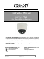
Instruction Manual
20Z704T-PZ10
Mini Speed Dome Camera
Prior to Using This Document: Videology reserves the right to modify the information in
this document as necessary and without notice. It is the user’s responsibility to be certain
they possess the most recent version of this document by going to www.videologyinc.com,
searching for the model number, and comparing revision letters on the respective
document, located in the document’s footer.
For technical assistance with this product, please contact the supplier from whom the
product was purchased.
Videology Imaging Solutions, Inc. USA
37M Lark Industrial Parkway
Greenville, RI 02828
Tel: 401-949-5332
Fax: 401-949-5276
Doc # INS 20Z704T-PZ10
Revision: B
Videology Imaging Solutions, B.V. Europe
Neutronenlaan 4
NL-5405 NH Uden, Netherlands
Tel: +31 (0) 413-256261
Fax: +31 (0) 413-251712
Issue Date: 08/13/2009
Page 1 of 40
Table Of Contents
`1. Document History.............................................................................................. 4
2. Important Safety Instructions ............................................................................. 4
3. Precautions ...................................................................................................... 5
4. Features .......................................................................................................... 6
5. Product & Accessories ........................................................................................ 7
5.1.
(10x/12x Zoom Models)............................................................................... 7
5.2.
Product & Accessories (Variable Focus Lens Model) .......................................... 7
5.3.
Options ..................................................................................................... 7
6. Parts Name & Functions ..................................................................................... 9
7. Installation ..................................................................................................... 10
7.1.
DIP Switch Setup ...................................................................................... 10
7.1.1.
Camera ID Setup ............................................................................... 10
7.1.2.
Communication Protocol Setup ............................................................. 10
7.1.3.
Termination Switch Setting .................................................................. 11
7.2.
Direct Installation on the Ceiling ................................................................. 12
7.3.
Installation using Ceiling Mount Bracket ....................................................... 13
7.4.
Installation using Wall Mount Bracket .......................................................... 14
7.5.
Cabling.................................................................................................... 15
7.5.1.
Power Connection............................................................................... 15
7.5.2.
RS-485 Communication....................................................................... 15
7.5.3.
Video Connection ............................................................................... 16
7.5.4.
Network Connection (Reserved for future network models)....................... 16
7.5.5.
Alarm Input Connection ...................................................................... 16
8. Check points before operation ........................................................................... 17
8.1.
Preset and Pattern Function Pre-Check......................................................... 17
8.2.
Starting OSD Menu ................................................................................... 17
8.3.
Reserved Preset........................................................................................ 17
8.4.
Preset ..................................................................................................... 18
8.5.
Swing ..................................................................................................... 18
8.6.
Pattern.................................................................................................... 19
8.7.
Group ..................................................................................................... 20
8.8.
Other Functions ........................................................................................ 20
9. OSD Display of Main Screen .............................................................................. 22
10.
Menu.......................................................................................................... 23
10.1.
General Rules of Key Operation for Menu .................................................. 23
10.2.
Main Menu............................................................................................ 23
10.3.
Display Setup ....................................................................................... 23
10.3.1.
Compass Direction Setup ................................................................. 23
10.4.
PRIVACY ZONE MASK Setup .................................................................... 24
10.4.1.
Privacy Zone Area Setup .................................................................. 24
10.4.2.
Privacy Zone Size Adjustment........................................................... 24
10.5.
CAMERA SETUP ..................................................................................... 25
10.5.1.
White Balance Setup ....................................................................... 25
10.5.2.
Auto Exposure Setup ....................................................................... 26
10.5.3.
White Balance Setup ....................................................................... 27
10.5.4.
Auto Exposure Setup ....................................................................... 27
10.6.
Motion Setup ........................................................................................ 28
10.6.1.
Parking Action Setup ....................................................................... 29
10.6.2.
Alarm Input Setup .......................................................................... 29
10.7.
PRESET Setup ....................................................................................... 30
10.7.1.
Edit Preset Scene ............................................................................ 31
10.7.2.
Edit Preset Label ............................................................................. 31
10.8.
Swing Setup ......................................................................................... 32
10.9.
Pattern Setup........................................................................................ 33
Doc # INS 20Z704T-PZ10
Revision: B
Issue Date: 08/13/2009
Page 2 of 40
10.9.1.
Edit Pattern....................................................................................
10.10.
Group Setup .........................................................................................
10.11.
Edit Group ............................................................................................
10.12.
System Initialize (10x Zoom Model) .........................................................
10.12.1.
Initial Configuration Table ................................................................
10.13.
System Initialize (Variable Focus Lens Model) ............................................
10.13.1.
Initial Configuration Table (Variable Focus Lens Model).........................
11.
Specifications ..............................................................................................
11.1.
Dimensions...........................................................................................
12.
Contact Information .....................................................................................
Doc # INS 20Z704T-PZ10
Revision: B
Issue Date: 08/13/2009
Page 3 of 40
33
34
34
35
36
37
37
38
39
40
1. Document History
Revision Issue Date Reason
Rev A
06-30-09
Initial release
Rev B
08-13-09
Section 4, 8.8, 10.5.2 revised
CN#
09-0101
09-0116
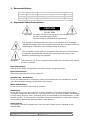
2. Important Safety Instructions
CAUTION
RISK OF ELECTRIC SHOCK
DO NOT OPEN
CAUTION:
To reduce the risk of electric shock, do not open covers.
No user serviceable parts inside.
Refer servicing to qualified service personnel.
This symbol is intended to alert the user to the presence of un-insulated
"dangerous voltage" within the product's enclosure that may be of sufficient
magnitude to constitute a risk of electric shock to persons.
This exclamation point symbol is intended to alert the user to the presence
of important operating and maintenance (servicing) instructions in the
literature accompanying the appliance.
WARNING:
To prevent the risk of fire or electric shock hazard, do not expose this camera
to rain or moisture.
Read Instructions
Read all of the safety and operating instructions before using the product.
Retain Instructions
Save these instructions for future reference.
Attachments / Accessories
Do not use attachments or accessories unless recommended by the manufacturer as they
may cause hazards, damage product and void warranty.
Water and Moisture
Do not use this product near water or moisture.
Installation
Do not place or mount this product in or on an unstable or improperly supported location.
Improperly installed product may fall, causing serious injury to a child or adult, and damage
to the product. Use only with a mounting device recommended by the manufacturer, or sold
with the product. To insure proper mounting, follow the manufacturer's instructions and use
only mounting accessories recommended by manufacturer.
Power source
This product should be operated only from the type of power source indicated on the
marking label.
Doc # INS 20Z704T-PZ10
Revision: B
Issue Date: 08/13/2009
Page 4 of 40
3. Precautions
Operating
• Before using, make sure power supply and others are properly connected.
• While operating, if any abnormal condition or malfunction is observed, stop using the
camera immediately and then contact your local dealer.
Handling
• Do not disassemble or tamper with parts inside the camera.
• Do not drop or subject the camera to shock and vibration as this can damage
camera.
• Care must be taken when you clean the clear dome cover. Especially, scratch and
dust will ruin your quality of camera.
Installation and Storage
• Do not install the camera in areas of extreme temperature, which exceed the
allowable range.
• Avoid installing in humid or dusty places.
• Avoid installing in places where radiation is present.
• Avoid installing in places where there are strong magnetic fields and electric signals.
• Avoid installing in places where the camera would be subject to strong vibrations.
• Never expose the camera to rain and water.
Doc # INS 20Z704T-PZ10
Revision: B
Issue Date: 08/13/2009
Page 5 of 40
4. Features
Camera Specifications
• CCD Sensor:
1/4" Interline Transfer CCD
• Zoom Magnification:
x10 Optical Zoom, x10 Digital Zoom (Max. x 100 Zoom) 10x Zoom Model
x12 Optical Zoom, x10 Digital Zoom (Max. x120 Zoom) 12x Zoom Model
Variable focus lens model (3.8mm~9.5mm), size 38x38 Variable Focus Lens Model
• True Day & Night Function with moveable IR cut filter
• Various Focus Mode: Auto-Focus / Manual Focus / Semi-Auto Focus.
(except the Variable Focus Lens model)
• Independent & Simultaneous Camera Characteristic Setup in Preset operation
Powerful Pan/Tilt Functions
•
Max. 360°/sec high speed Pan/Tilt Motion
Using Vector Drive Technology, Pan/Tilt motions are achieved in the shortest path.
•
As a result, time to target view is reduced dramatically and the video on the monitor
is very natural to watch.
•
For jog operation using a controller, since ultra slow speed 0.05°/sec can be
reached, it is very easy to position a camera to the desired target view. Additionally
it is easy to move the camera to a desired position with zoom-proportional pan/tilt
movement.
Preset, Pattern, Swing, Group, Privacy Mask and More…
• Max. 127 Presets are assignable and characteristics of each preset can be set up
independently, such as White Balance, Auto Exposure, Label and so on.
• Max. 8 set of Swing actions can be stored. This enables camera to move repetitively
between two preset positions with a designated speed.
• Max. 4 Patterns can be recorded and played back. This enables you to move the
camera from any PTZ trajectory recorded by the joystick movement as closely as
possible.
• Max. 8 set of Group actions can be stored. This enables you to move the camera
repetitively from a combination of Presets or Patterns or Swings. A Group is
composed of max. 20 entities of Preset/Pattern/Swings.
• Privacy Masks are assignable, so as not to intrude on other’s privacy. (4 Privacy
Zones)
PTZ (Pan/Tilt/Zoom) Control
• With RS-485 communication, a max. of 255 cameras can be controlled. Pelco-D or
Pelco-P protocol can be selected as a control protocol in the current version of
firmware.
OSD (On Screen Display) Menu
• OSD menu is provided to display the status of a camera and to configure the
functions interactively.
• The information such as Camera ID, Pan/Tilt Angle, Alarm Input and Preset can be
displayed on screen.
Alarm I/O Functions
• 4 alarm sensor inputs are available.
• To prevent external electric noise and shock completely, the alarm sensor inputs are
decoupled with a photo isolator.
• The signal range of sensor input is from DC 5.0 to 12.0 volts to adopt to various
applications.
Doc # INS 20Z704T-PZ10
Revision: B
Issue Date: 08/13/2009
Page 6 of 40
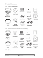
5. Product & Accessories
5.1.
(10x/12x Zoom Models)
Plastic Anchor
5.2.
Product & Accessories (Variable Focus Lens Model)
Plastic Anchor
5.3.
Options
Doc # INS 20Z704T-PZ10
Revision: B
Issue Date: 08/13/2009
Page 7 of 40
Ceiling Mount Bracket
Doc # INS 20Z704T-PZ10
Revision: B
Wall Mount Bracket
Issue Date: 08/13/2009
Page 8 of 40
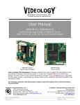
6. Parts Name & Functions
Main Unit / Surface Mount Bracket
Back of Main Unit
Dome Cover (Bubble)
Do not remove protection vinyl from the bubble before
finishing the installation process, thus protecting the bubble
from scratches or dust.
Selectable clear or smoke types.
Surface Mount Base
This is used to install the camera directly on the ceiling. After
separating this cover, attach this directly to ceiling.
Camera must be assembled at the last stage.
Fixing Screw
Fixes main unit to surface mount bracket.
Cabling Terminal Block
During installation, Power, Video, Communication, Alarm Input
cables are to be connected on to this cabling terminal block.
DIP Switch
Adjusts camera ID and protocols.
Focus Handle
Adjusting the focus lens (FAR/NEAR)
Zoom Handle
Adjusting the zoom lens (TELE/WIDE)
Service Monitor Connector
User service monitor connector assists setting the camera
angle and focus when installing
DC Level Volume
Adjusting the DC iris level
Doc # INS 20Z704T-PZ10
Revision: B
Issue Date: 08/13/2009
Page 9 of 40
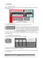
7. Installation
7.1.
DIP Switch Setup
Before you install the camera, you should set the DIP switches to configure the camera ID,
communication protocol.
7.1.1. Camera ID Setup
ID number of camera is set using dip switch. The example is shown bellow.
Pin
ID Value
ex) ID=5
ex) ID=10
1
1
on
off
2
2
off
on
3
4
on
off
4
8
off
on
5
19
off
off
6
32
off
off
7
64
off
off
8
128
off
off
The range of ID is 1~255. Do not use 0 as camera ID. Factory default of Camera ID is 1.
If you want to control a certain camera, you must match the camera ID with Cam ID setting
of DVR or Controller.
7.1.2. Communication Protocol Setup
Select the appropriate Protocol with DIP switch combination.
Switch State
P0
(Pin 1)
P2
(Pin 2)
P3
(Pin 3)
Protocol
OFF
ON
OFF
ON
OFF
OFF
ON
ON
Others
OFF
OFF
OFF
OFF
PELCO-D, 2400 bps
PELCO-D, 9600 bps
PELCO-P, 4800 bps
PELCO-P, 9600 bps
Reserved
If you want to control using a DVR or P/T controller, their protocol must be identical to the
camera. Otherwise, you cannot control the camera.
If you changed camera protocol by changing DIP S/W, the change will be effective after you
reboot the camera.
Doc # INS 20Z704T-PZ10
Revision: B
Issue Date: 08/13/2009
Page 10 of 40
Factory default of protocol is “Pelco-D, 2400 bps”.
7.1.3. Termination Switch Setting
Termination switch (Pin 4) is used in cases listed below.
• Long-distance communication between the controller and the camera (1-to-1
connection)
When the connecting distance between the two units is especially long,
communication errors may occur due to the impedance of transmission cable. In this
case, set the termination switch of both units to ON.
•
Controlling multiple cameras (Multiple connection)
The camera may not operate correctly if multiple cameras are connected and
controlled. In this case, set the termination switch of the controller and the last
connected camera to ON and the switch of other cameras is OFF.
Ex) Using the Terminating Resistance
Doc # INS 20Z704T-PZ10
Revision: B
Issue Date: 08/13/2009
Page 11 of 40
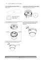
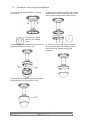
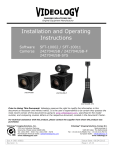
7.2.
Direct Installation on the Ceiling
1) To pass cables to upside of ceiling,
please, make about 50~60mm hole on the
ceiling panel.
2) Detach the marked part from the rubber
gasket and screw the surface mount bracket
to the ceiling with fixing screws.
You can use “Guide
Pattern” for the
making holes.
3) Wire cables to terminal block and connect
the terminal blocks to main unit.
4) Insert the main body into the surface
mount bracket with the molding lines on
each part being aligned and turning
clockwise.
5) Insert the fixing screw tightly and detach
the protection vinyl from dome cover.
Doc # INS 20Z704T-PZ10
Revision: B
Issue Date: 08/13/2009
Page 12 of 40
7.3.
Installation using Ceiling Mount Bracket
1) Screw ceiling mount bracket to ceiling
with screws.
2) Detach the marked part from the rubber
gasket and screw the mounting base to the
ceiling mount bracket with fixing screws.
You can use “Guide
Pattern” for making
holes.
3) Wire cables to terminal block and connect
the terminal blocks to main unit.
4) Insert the main body into the ceiling
mount bracket with the molding lines on
each part being aligned and turning
clockwise.
5) Insert the fixing screw tightly and detach
the protection vinyl from dome cover.
Doc # INS 20Z704T-PZ10
Revision: B
Issue Date: 08/13/2009
Page 13 of 40
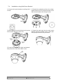
7.4.
Installation using Wall Mount Bracket
1) Screw wall mount bracket to ceiling with 3
screws.
2) Detach the marked part from the rubber
gasket and screw the mounting base to the
wall mount bracket with fixing screws.
3) Wire cables to terminal block and connect
the terminal blocks to main unit.
4) Insert the main body into the wall mount
bracket with the molding lines on each part
being aligned and turning clockwise.
5) Insert the fixing screw tightly and detach
the protect the vinyl from dome cover.
Doc # INS 20Z704T-PZ10
Revision: B
Issue Date: 08/13/2009
Page 14 of 40
7.5.
Cabling
7.5.1. Power Connection
Please, check the voltage and current capacity of rated power carefully. Rated power is
indicated in the back of main unit.
Rated Power
DC 12V
AC 24V
Input Voltage Range
DC 11V ~ 18V
AC 17V ~ 29V
Current Consumption
0.8 A
0.4 A
To the case of variable focus lens model is supported only DC12V/1A.
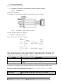
7.5.2. RS-485 Communication
For PTZ control, connect this line to a keyboard, or DVR, or other RS-485 control (i.e. PC).
To control multiple cameras, RS-485 communication lines are connected in parallel as shown
below.
Doc # INS 20Z704T-PZ10
Revision: B
Issue Date: 08/13/2009
Page 15 of 40
7.5.3. Video Connection
Connect with BNC coaxial cable
7.5.4. Network Connection (Reserved for future network models)
7.5.4.1.
NETWORK 1
Connect with LAN cable.
If LAN cable is not connected properly, This product can not be operate.
7.5.4.2.
NETWORK 2 (Reserved for supplier.)
DO NOT CONNECT WITH ANY DEVICE.
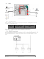
7.5.5. Alarm Input Connection
Sensor Input (open collector example)
Before connecting sensors, check driving voltage and output signal type of the sensor. Since
output signals of sensors are either Open Collector or Voltage Output type. In general, the
cabling must be done properly depending on which is used.
Signal
IN COM+
IN1−, IN2−, IN3−, IN4−
Description
Connect (+) cable of electric power source for Sensors to this
port as shown in the circuit above.
Connect output of sensors for each port as shown in the circuit
above.
If you want to use Alarm Input, the types of sensor must be selected in the OSD menu.
The sensor types are Normal Open and Normal Closed. If the sensor type is not selected
properly, the alarm can be activated in reverse.
Normal Open
Normal Close
Doc # INS 20Z704T-PZ10
Revision: B
Output Voltage is high state when sensor is activated
Output Voltage is high state when sensor is not activated
Issue Date: 08/13/2009
Page 16 of 40
8.
Check points before operation
Before power is applied, please check the cables carefully.
The camera ID of the controller must be identical to that of the target camera. The camera
ID can be checked by reading the DIP switch of the camera, or the boot window on powerup.
If your controller supports multi-protocols, the protocol must be changed to match that of
the camera.
If you changed the camera protocol by changing the DIP switch, the change will take effect
only after you reboot the camera.
Since the operation method can be different for each controller available, refer to the
manual for your controller if camera cannot be controlled properly. The operation of this
manual is based on the standard Pelco® Controller.
8.1.
Preset and Pattern Function Pre-Check
Check how to operate preset and pattern function with controller or DVR in advance to
operate camera function fully when using controller or DVR.
Refer to the following table when using standard Pelco® protocol controller.
< Go Preset >
< Set Preset >
< Run Pattern >
< Set Pattern >
Input [Preset Number] and press [Preset] button shortly.
Input [Preset Number] and press [Preset] button for more than 2
seconds.
Input [Pattern Number] and press [Pattern] button shortly.
Input [Pattern Number] and press [Pattern] button for more than 2
seconds.
If controller or DVR has no pattern button or function, use shortcut keys with preset
numbers. For more information, refer to Section 8.3 in this manual.
8.2.
Starting OSD Menu
Function Using the OSD menu, Preset, Pattern, Swing, Group and Alarm Input function can
be configured for each application.
Enter Menu <Go Preset> [95]
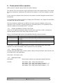
8.3.
Reserved Preset
Description
Some Preset numbers are reserved to special functions.
Function
<Go
<Go
<Go
<Go
Doc # INS 20Z704T-PZ10
Revision: B
Preset>
Preset>
Preset>
Preset>
[95] : Enters into OSD menu
[131~134] Runs Pattern Function 1 ~ 4
[141~148] Runs Swing Function 1 ~ 8
[151~158] Runs Group Function 1 ~ 8
Issue Date: 08/13/2009
Page 17 of 40
8.4.
Preset
Function
Max. 127 positions can be stored as Preset position. The Preset
number can be assigned from 1 to 128, but 95 is reserved for starting
OSD menu.
Camera characteristics (i.e. White Balance, Auto Exposure) can be set
up independently for each preset. Label should be blank and "Camera
Adjust" should be set to "GLOBAL" as default. All characteristics can be
set up in OSD menu.
Set Preset
<Set Preset> [1~128]
Run Preset
<Go Preset> [1~128]
Delete Preset
To delete Preset, use OSD menu.
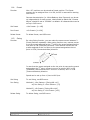
8.5.
Swing
Function
By using Swing function, you can make the camera move between 2
Preset positions repeatedly. When swing function runs, camera moves
from the preset assigned as the 1st point to the preset assigned as the
2nd point in CW (Clockwise) direction. Then camera moves from the
preset assigned as the 2nd point to the preset assigned as the 1st
point in CCW (Counterclockwise) direction.
In case that the preset assigned as the 1st point is same as the preset
assigned as the 2nd point, camera turns on its axis by 360° in CW
(Clockwise) direction and then it turns on its axis by 360° in CCW
(Counterclockwise) direction.
Speed can be set up from 1°/sec to 180°/sec.
Set Swing
To set Swing, use OSD menu.
Run Swing
Method 1) <Run Pattern> [Swing NO.+10]
ex) Run Swing 3: <Run Pattern> [13]
Method 2) <Go Preset> [Swing NO.+140]
ex) Run Swing 3: <Go Preset> [143]
Delete Swing
To delete Swing, use OSD menu.
Doc # INS 20Z704T-PZ10
Revision: B
Issue Date: 08/13/2009
Page 18 of 40
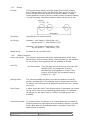
8.6.
Pattern
Function
A Pattern Function memorizes the path of the joystick controller
for an assigned time and relays the path exactly as it
memorized.
4 Patterns are available and a Maximum of 1200
communication commands can be stored in a pattern.
Set Pattern
Pattern can be created by one of following two methods.
Method 1) <Set Pattern> [Pattern NO.]
Pattern editing screen is displayed as below.
Movement by Joystick and preset movement can be
memorized in a pattern.
The total memory size is displayed in a progress bar.
To save the recording press NEAR, and to cancel press
the FAR key.
Method 2) OSD
Using OSD Menu: See the section “How to use OSD
Menu”.
Run Pattern
Method 1) <Run Pattern> [Pattern NO.]
ex) Run Pattern 2 : <Run Pattern> [2]
Method 2) <Go Preset> [Pattern NO.+130]
ex) Run Pattern 2: <Go Preset> [132]
Delete Pattern
Doc # INS 20Z704T-PZ10
Revision: B
To delete Pattern, use OSD menu.
Issue Date: 08/13/2009
Page 19 of 40
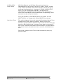
8.7.
Group
Function
The Group function allows running a sequence of Presets, Pattern
and/or Swings. Max 8 group can be stored. Each group can have a
max of 20 action entities, which can be preset, pattern or swing.
Preset speed can be set up and the repeat number of Pattern & Swing
in the Group setup. Dwell time between actions can be set up also.
Set Group
Use OSD Menu to create a Group.
Run Group
Method 1) <Run Pattern> [Group NO.+20]
ex) Run Group 7 : <Run Pattern> [27]
Method 2) <Go Preset> [Group NO.++150]
ex) Run Group 7 : <Go Preset> [157]
Delete Group
8.8.
To delete Group, use OSD menu.
Other Functions
Power (Up Action)
This function resumes the last action executed before power down.
Most actions, such as Preset, Pattern, Swing and Group, are available
for this function, but Jog actions are not available to resume.
Auto Flip
10x Zoom Model
If the tilt angle arrives at the top of tilt orbit (90°
straight down), the images are reversed
automatically and F appears in screen. If this
function is set to OFF, tilt movement range is
limited to 0° ~ 95°.
Parking Action
This function enables the ability to locate the camera to a specific
position automatically. If the operator doesn’t operate the controller
for awhile, the Park Time can be defined as an interval from 1 minute
to 4 hours.
Alarm Input
4 Alarm Inputs are used. If an external sensor is activated, the camera
can be set to move to a corresponding preset position. It should be
noted that the last alarm input is in effect if multiple sensors are
activated.
Privacy Zone Mask
To protect privacy, a maximum of 4 Privacy Masks can be created in
arbitrary position to hide objects such as windows, shops or a private
house. With Spherical Coordinates system, powerful Privacy Zone
Mask function is possible.
Doc # INS 20Z704T-PZ10
Revision: B
Issue Date: 08/13/2009
Page 20 of 40
GLOBAL/LOCAL
Image Setup
WB (White Balance) and AE (Auto Exposure) can be set up
independently for each preset. There are 2 modes, "Global" mode &
"Local" mode. The Global mode means that WB or AE can be set up
totally and simultaneously for all presets in "ZOOM CAMERA SETUP"
menu. The Local mode means that WB or AE can be set up
independently or separately for each preset in each preset setup
menu. Each Local WB/AE value should activate correspondingly when
camera arrives at each preset location.
During jog operation, Global WB/AE values are applied. All Local
WB/AE value do not change when Global WB/AE value changes.
Semi Auto Focus
This mode exchanges focus mode automatically between Manual Focus
mode and Auto Focus mode by operation. Manual Focus mode
activates in preset operation and Auto Focus mode activates during jog
operation. With Manual mode at presets, Focus data is memorized in
each preset in advance and camera calls focus data in correspondence
with presets as soon as camera arrives at a preset, eliminating focus
hunt.
Focus mode changes to Auto Focus mode automatically when jog
operation starts.
Doc # INS 20Z704T-PZ10
Revision: B
Issue Date: 08/13/2009
Page 21 of 40
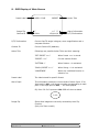
9. OSD Display of Main Screen
Preset Label
Image Flip
Camera ID
LABEL 12345
F
CAM 1
PRESET
Action Title
I: 1 ? ? ?
15/4/x1/N
Alarm Information
P/T/Z Information
P/T/Z Information
Current Pan/Tilt angle in degree, zoom magnification and a
compass direction.
Camera ID
Current Camera ID (Address).
Action Title
Followings are possible Action Titles and their meaning.
"SET PRESET ×××"
When Preset ××× is stored
"PRESET ×××"
Current camera Preset
"PATTERN ×"
When Pattern × is activated
"SWG×/PRESET ×××"
When Swing × is in activated
"UNDEFINED"
When any undefined function is
called to run
Preset Label
The Label stored for specific Preset.
Alarm Input
This information shows the current state of Alarm Input. If an
Input point is ON, it will show a number corresponding to each
point. If an Input point is OFF, '-' will be displayed.
Ex) Point 2 & 3 of inputs are ON, OSD will show as below
I:-23-
Image Flip
Doc # INS 20Z704T-PZ10
Revision: B
Shows that images are currently reversed by Auto Flip
Function.
(Only 10x Zoom model)
Issue Date: 08/13/2009
Page 22 of 40
10.Menu
10.1. General Rules of Key Operation for Menu
•
•
•
•
•
•
•
The menu items surrounded with “< >” always have a sub menu.
To enter all menu levels, press NEAR key.
To back up one menu level, press FAR key.
To move from item to item in the menu, use the joystick with Up/Down or
Left/Right motion.
Use NEAR key to select an item
To change a value of an item, use Up/Down of the joystick in the controller.
Press NEAR key again to save values or Press FAR key to cancel values.
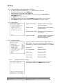
10.2. Main Menu
System Information
Displays system information
and configuration.
Display Setup
Enable/Disable of OSD display
on Main Screen.
Dome Camera Setup
Configure various functions of
this camera.
System Initialize
Initializes system configuration
and sets all data to factory
default configuration.
10.3. Display Setup
This menu defines Enable/Disable of OSD display on
Main Screen. If an item is set to be AUTO, the item is
displayed only when the camera position it is changed.
10.3.1.
Camera ID
[ON/OFF]
PTZ Information
[ON/OFF/AUTO]
Action Title
[ON/OFF/AUTO]
Preset Label
[ON/OFF/AUTO]
Alarm Input
[ON/OFF/AUTO]
Compass Direction Setup
Set North to assign compass direction as criteria.
Move camera and press NEAR button to save.
Doc # INS 20Z704T-PZ10
Revision: B
Issue Date: 08/13/2009
Page 23 of 40
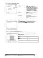
10.4. PRIVACY ZONE MASK Setup
Select area in image to mask.
Mask No
[1~4]
Select Mask number. If the
selected mask contains data, a
blank space appears beneath the
number selected. Otherwise,
“UNDEFINED” will be displayed.
10.4.1.
Display
[ON/OFF]
Enables or disables selected
mask in the image.
Clear Mask
[CANCEL/OK]
Deletes data in the selected
mask.
Privacy Zone Area Setup
Select EDIT MASK, then move camera to desired
scene. Then press NEAR to adjust mask size.
10.4.2.
Privacy Zone Size Adjustment
Adjust mask size. Use joystick or arrow buttons to
adjust mask size.
(Left/Right)
Adjusts mask width.
(Up/Down)
Adjusts mask height.
Press NEAR to save, or FAR to cancel.
Doc # INS 20Z704T-PZ10
Revision: B
Issue Date: 08/13/2009
Page 24 of 40
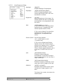
10.5. CAMERA SETUP
Setup the general functions of zoom camera module.
[AUTO/MANUAL/SEMIAUTO]
Focus Mode
Sets camera focus mode.
SEMIAUTO Mode
This mode changes focus mode
automatically between Manual Focus
mode and Auto Focus mode. Manual
Focus mode activates on preset
operation and Auto Focus mode
activates during jog operation.
With Manual mode at presets, Focus
data is memorized for each preset in
advance. Any additional activity in the
scene is ignored so the target stays
focused.
10.5.1.
Digital Zoom
[ON/OFF]
Sets digital zoom function to ON/OFF.
If this is set to OFF, optical zoom
function runs but zoom function stops
at the end of optical zoom
magnification.
Line Lock
[ON/OFF]
If Line lock sync is ON, video signal is
synchronized with AC power. Video will
fluctuate after setting is changed,
verifying the external sync.
White Balance Setup
Doc # INS 20Z704T-PZ10
Revision: B
WB Mode
[AUTO/MANUAL]
In Manual mode, Red and Blue level
can be set up manually
Red Adjust
[10~60]
Blue Adjust
[10~60]
Issue Date: 08/13/2009
Page 25 of 40
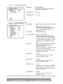
10.5.2.
Auto Exposure Setup
Backlight
[ON/OFF]
Enables Backlight Compensation
Day/Night
[AUTO1/AUTO2/DAY/NIGHT]
AUTO1 changes Day/Night mode
sooner than AUTO2, DAY is full color
and NIGHT is full B/W
Brightness
[0~100]
Adjusts brightness of the image. Iris,
Shutter Speed and Gain are adjusted
automatically in correspondence with
this value.
IRIS
[AUTO/MANUAL (0~100)]
If Iris is set to Auto, Iris should have
highest priority in adjusting AE and
Shutter Speed should be fixed.
If Iris is set to Manual, Iris should be
fixed and Iris has lower priority in
adjusting AE, in comparison with
others.
Shutter Speed
ESC/A.Flicker/Manual
(x2 ~ ×128 frames or 1/60
~1/120000 sec)
If Iris is set to Manual and Shutter
Speed is set to ESC, Shutter Speed
should have highest priority. If Shutter
Speed is set to A.Flicker, to remove
Flicker, Shutter Speed should be set to
1/100 sec. for NTSC and 1/120 for
PAL.
AGC
[OFF/NORMAL/HIGH]
Enhances image brightness
automatically in case that luminance
level of image signal is too low (Day or
Night mode only).
SSNR
[OFF/LOW/MIDDLE/HIGH]
Enhances images by deducting noises
when gain level of images is too high.
SENS-UP
[AUTO(2~128)/OFF]
Activates Slow Shutter function when
luminance of image (signal) is too
dark.
The higher the number, the slower the
shutter speed.
Doc # INS 20Z704T-PZ10
Revision: B
Issue Date: 08/13/2009
Page 26 of 40
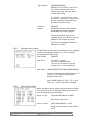
10.5.3.
10.5.4.
White Balance Setup
WB MODE
[AUTO/MANUAL]
In Manual mode, Red and Blue level
can be set up manually
RED ADJUST
[10~60]
BLUE ADJUST
[10~60]
Auto Exposure Setup
BACKLIGHT
DAY/NIGHT
SLOW SHUTTER
AE MODE
[OFF/C1/C2/L1/L2/U1/U2/D1/D2/R1/
R2]
Sets Backlight Compensation.
The reference position and the level
of BLC are selectable. Refer to the
table below. NOTE 1 next page)
[AUTO/DAY/NIGHT]
[OFF/2~128 FIELDS]
Activates SLOW SHUTTER function
when luminance of image (signal) is
too dark. Select the number of fields
to add together (integrate). It is only
available when DAY/NIGHT mode is
DAY.
[AUTO/SHUTTER/IRIS/AGC/MANUAL]
There are five modes of Auto
Exposure function.
With the exception of AUTO mode, all
modes can be selected when
DAY/NIGHT mode is DAY and SLOW
SHUTTER mode is OFF.
IRIS LEVEL
[0~255]
It can be set when AE is in IRIS
mode or MANUAL mode.
GAIN LEVEL
[0~255]
It can be set when AE is in AGC
mode or MANUAL mode.
SHUTTER SPD
[0~27]
It can be set when AE is in SHUTTER
SPEED mode or in MANUAL mode.
As for setting value, refer to the table
below. NOTE 2 next page)
BRIGHTNESS
[0~96]
It can be set when AE is not in
MANUAL mode.
NOTE 1) Backlight Compensation (weight refers to the amount of brightness compensation)
Doc # INS 20Z704T-PZ10
Revision: B
Issue Date: 08/13/2009
Page 27 of 40
Value
C1
L1
U1
D1
R1
Description
Low
Low
Low
Low
Low
weight
weight
weight
weight
weight
at
at
at
at
at
the
the
the
the
the
Value
center of the screen
left of the screen
upper of the screen
lower of the screen
right of the screen
C2
L2
U2
D2
R2
Description
High
High
High
High
High
weight
weight
weight
weight
weight
at
at
at
at
at
the
the
the
the
the
center of the screen
left of the screen
upper of the screen
lower of the screen
right of the screen
NOTE 2) Shutter Speed Table (NTSC)
Value
0
1
2
3
4
5
6
Description
1/60 sec
1/125 sec
1/150 sec
1/200 sec
1/250 sec
1/300 sec
1/350 sec
Value
7
8
9
10
11
12
13
Description
1/400 sec
1/450 sec
1/500 sec
1/600 sec
1/700 sec
1/800 sec
1/900 sec
Value
14
15
16
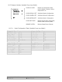
17
18
19
20
Description
1/1000 sec
1/1100 sec
1/1300 sec
1/1500 sec
1/1600 sec
1/1800 sec
1/2000 sec
Value
21
22
23
24
25
26
27
Description
1/2500 sec
1/2500 sec
1/3000 sec
1/3500 sec
1/4000 sec
1/6000 sec
1/10000 sec
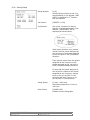
10.6. Motion Setup
Setup the general functions of Pan/Tilt motions.
Motion Lock
[ON/OFF]
Holds all motion setup configurations.
Note: If Motion Lock is set to ON, it is
impossible to set up and delete
Preset, Swing, Pattern and Group. It
is possible only to run those
functions.
To set up and delete those functions,
enter the OSD menu.
Doc # INS 20Z704T-PZ10
Revision: B
Power Up
Action
[ON/OFF]
Refer to “Other Functions" section.
Auto Flip
[ON/OFF]
Refer to “Other Functions" section.
Jog Max Speed
[1°/sec ~360°/sec]
Sets maximum jog speed.
Jog speed is inversely proportional to
zoom magnification. As zoom
magnification goes up, pan/tilt speed
goes down.
Issue Date: 08/13/2009
Page 28 of 40
Jog Direction
[INVERSE/NORMAL]
Setting this to ‘Inverse’, the view in
the screen is moving the same
direction with jog, panning, and in
reverse with tilting.
If ‘Normal’ is selected, the view in
the screen is moving in reverse of the
above: opposite direction panning,
and same direction tilting.
Freeze in
Preset
[ON/OFF]
Activates a function that holds the
image between preset selections,
eliminating the moving images.
As soon as camera stops at the
selected preset, the camera resumes
displaying live images at preset.
This function availability should be
different by models.
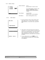
10.6.1.
Parking Action Setup
If Park Enable is set to ON, the camera runs an assigned
function automatically if there is no PTZ command
during assigned "Wait Time".
Park Enable
[ON/OFF]
Wait Time
Park Action
[1 minute ~ 4 hour]
The time is displayed with
"hh:mm:ss" format and you can
change this in 1 min increments.
[HOME/PRESET/PATTERN/SWING/GROUP]
Camera is activated to selected function. If
there is no PTZ command during the
assigned "Wait Time".
Note: HOME position is Pan 0, Tilt 0, and
Zoom x1 – Position cannot be changed
10.6.2.
Alarm Input Setup
Match the Alarm sensor output type and select a preset.
If an external sensor is activated, camera will move to
this corresponding preset position.
Alarm × Type
[Normal OPEN/Normal CLOSE]
Sets sensor input type.
Alarm × Action
[NOT USED/PRESET 1~128]
Assign Preset position to each Alarm
input.
Doc # INS 20Z704T-PZ10
Revision: B
Issue Date: 08/13/2009
Page 29 of 40
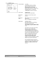
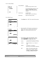
10.7. PRESET Setup
Preset Number
[1~128]
If a selected preset is already
defined, camera moves to predefined position and preset
characteristics such as Label and
Relay Outputs show on monitor. If a
selected preset is not defined,
“UNDEFINED” shows on monitor.
Clear Preset
[CANCEL/OK]
Delete current Preset data
Edit Preset
Scene
Redefine current Preset scene
position.
Edit Preset
Label
Edits Label to show on monitor when
preset runs.
MAX. 10 alphabets are allowed.
CAM Adjust
[GLOBAL/LOCAL]
WB (White Balance) and AE(Auto
Exposure) can be set up
independently for each preset. There
are 2 modes, "Global" mode & "Local"
mode.
The Global mode means that WB or
AE can be set up totally and
simultaneously for all presets in
"ZOOM CAMERA SETUP" menu and
the Local mode means that WB or AE
can be set up independently for each
preset in each preset setup menu.
Each Local WB/AE value should
activate correspondingly when
camera arrives at each preset
location. During jog operation, Global
WB/AE value will be reactivated.
All Local WB/AE values should not
change although Global WB/AE value
changes. If “Local’’ is selected, the
Menu to set WB/AE shows on the
monitor.
Doc # INS 20Z704T-PZ10
Revision: B
Issue Date: 08/13/2009
Page 30 of 40
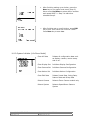
10.7.1.
Edit Preset Scene
1. Using the Joystick, move the camera to a
desired position.
2. By pressing NEAR key, save current PTZ data.
3. Press FAR key to cancel.
10.7.2.
Edit Preset Label
1. Edits the label to show on the monitor when the
camera arrives at presets. In Edit Label menu, a
vertical rectangular is the cursor. As letters are
entered, the cursor moves to the next space.
2. Using Left/Right/Up/Down of joystick, move
to an appropriate character from the Character
set. To choose that character, press the NEAR
key.
If you want to use blank, choose Space
character (" "). If you want to delete a character
before, use back space character ("
").
3. If you have finished the Label editing, move
cursor to "OK" and press NEAR key to save
completed label. To abort current entries, move
cursor to "Cancel" and press NEAR key.
Doc # INS 20Z704T-PZ10
Revision: B
Issue Date: 08/13/2009
Page 31 of 40
10.8. Swing Setup
Swing Number
[1~8]
Selects Swing number to edit. If a
selected Swing is not defined, "NOT
USED" is displayed in 1st Position
and 2nd Position
1st Position
[PRESET 1~128]
2nd Position
Set up the 2 position for Swing
function. If a selected preset is not
defined, "UNDEFINED" will be
displayed as shown below.
When swing function runs, camera
moves from the preset assigned as
the 1st point to the preset assigned
as the 2nd point in CW (Clockwise)
direction.
Then camera moves from the preset
assigned as the 2nd point to the
preset assigned as the 1st point in
CCW (Counterclockwise) direction.
In case that the preset assigned in
the 1st point is same as the preset
assigned as the 2nd point, camera
turns on its axis by 360° in CW
direction and then it turns on its
axis by 360° in CCW direction.
Doc # INS 20Z704T-PZ10
Revision: B
Swing Speed
[1°/sec ~180°/sec]
Sets Swing speed from 1°/sec to
180°/sec.
Clear Swing
[CANCEL/OK]
Deletes current Swing data.
Issue Date: 08/13/2009
Page 32 of 40
10.9. Pattern Setup
Pattern Number
[1~4]
Selects Pattern number to edit.
If a selected pattern number is not
defined, "UNDEFINED" will be
displayed under selected pattern
number.
10.9.1.
Clear Pattern
[CANCEL/OK]
Deletes data in current pattern
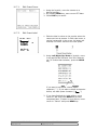
Edit Pattern
Opens editing pattern menu.
Edit Pattern
1. By using Joystick, move to start position with
appropriate zoom. To start pattern recording,
press NEAR key. To exit this menu, press FAR
key.
2. Move and/or zoom the camera with joystick of
controller or run preset function to memorize the
path for the selected pattern. The total memory
size is displayed in the display bar. Maximum
1200 communication commands can be stored in
a pattern.
3. To save data and exit, press NEAR key. To
cancel recording and delete the recorded data,
press FAR key.
Doc # INS 20Z704T-PZ10
Revision: B
Issue Date: 08/13/2009
Page 33 of 40
10.10. Group Setup
Group Number
[1~8]
Selects Group number to edit.
If a selected Group number is not
defined, "UNDEFINED" will be
displayed under selected Group
number.
Clear Group
[CANCEL/OK]
Deletes data in current Group
Edit Group
Opens edit Group menu.
10.11.Edit Group
1. Press Near key in “NO” list to start Group setup.
2. Note that MAX. 20 Functions are allowed in a
Group. Move cursor up/down and press the
Near key to select group number set up.
3. Set up Action, Dwell time and Option. Move
cursor Left/Right to select items and move
cursor Up/Down to change each value.
Doc # INS 20Z704T-PZ10
Revision: B
Action
[NONE/PRESET/SWING/PATTERN]
(###)
Select function # (i.e. Preset 1 ~
128)
DWELL
[0 second ~ 4 minutes]
Sets Dwell Time between functions
OPT
Option. Set preset speed when
preset is set in Action. Set the
number of repeats when Pattern
or Swing is selected in Action
Issue Date: 08/13/2009
Page 34 of 40
4.
After finishing setting up an Action, press the
Near key to one-upper level menu (Step 2).
Move cursor Up/Down to select Action number
and repeat Step 2 ~ Step 3 to edit other
selected Groups.
5.
After finishing set up on all Actions, press FAR
key to exit. Then cursor will move to “SAVE”.
Press Near key to save data.
10.12.System Initialize (10x Zoom Model)
Doc # INS 20Z704T-PZ10
Revision: B
Clear All Data
Deletes all configuration data such
as display, camera, motion setup
and so on.
Clear Display Set
Initializes Display Configuration
Clear Camera Set
Initializes Camera Configuration
Clear Motion Set
Initializes Motion Configuration
Clear Edit Data
Deletes Preset Data, Swing Data,
Pattern Data and Group Data
Reboot Camera
Reboots Zoom Camera module only
Reboot System
Reboots Speed Dome Camera
System
Issue Date: 08/13/2009
Page 35 of 40
10.12.1. Initial Configuration Table
Display Configuration
Camera ID
ON
PTZ Information
AUTO
Action Title
AUTO
Preset Label
AUTO
Alarm Input
AUTO
North Direction
Pan 0°
Privacy Zone
Undefined
Motion Configuration
Motion Lock
OFF
Power Up Action
ON
Auto Flip
ON
Jog Max Speed
120°/sec
Jog Direction
INVERSE
Freeze In Preset
OFF
Park Action
OFF
Alarm Action
OFF
Doc # INS 20Z704T-PZ10
Revision: B
Camera Configuration
Focus Mode
SemiAuto
Digital Zoom
ON
Line Lock
OFF
White Balance
AUTO
Image Flip
OFF
Backlight
OFF
Day&Night
AUTO1
Brightness
25
Iris
AUTO
Shutter
ESC
AGC
NORMAL
SSNR
MIDDLE
SENS-UP
AUTO (4 Frame)
User Edit Data
Preset 1~128
Undefined
Swing 1~8
Undefined
Pattern 1~4
Undefined
Group 1~8
Undefined
Issue Date: 08/13/2009
Page 36 of 40
10.13.System Initialize (Variable Focus Lens Model)
CLEAR ALL DATA
Deletes all configuration data
such as display, camera, motion
setup and so on.
CLEAR DISPLAY SET
Initializes Display Configuration
CLEAR CAMERA SET
Initializes Camera Configuration
CLEAR MOTION SET
Initializes Motion Configuration
CLEAR EDIT DATA
Deletes Preset Data, Swing Data,
Pattern Data and Group Data
REBOOT SYSTEM
Reboots Speed Dome Camera
10.13.1. Initial Configuration Table (Variable Focus Lens Model)
Display Configuration
CAMERA ID
ON
PTZ INFORMATION
AUTO
ACTION TITLE
AUTO
PRESET LABEL
AUTO
ALARM INPUT
AUTO
NORTH DIRECTION
Pan 0°
PRIVACY ZONE
UNDEFINED
Camera Configuration
DIGITAL ZOOM
ON
LINE LOCK
OFF
BACKLIGHT
OFF
DAY/NIGHT
ON
AGC MODE
AUTO
FLICKERLESS
OFF
SENS UP
AUTO
Motion Configuration
MOTION LOCK
OFF
PWR UP ACTION
ON
AUTO FLIP
ON
JOG MAX SPEED
120°/sec
JOG DIRECTION
INVERSE
PARK ACTION
OFF
ALARM ACTION
OFF
User Edit Data
PRESET 1~128
SWING 1~8
PATTERN 1~4
GROUP 1~8
Doc # INS 20Z704T-PZ10
Revision: B
Issue Date: 08/13/2009
Page 37 of 40
UNDEFINED
UNDEFINED
UNDEFINED
UNDEFINED
11. Specifications
Electrical
Image Sensor
Active Pixels (HxV)
Total Pixels (HxV)
Scanning System
Scanning Frequency (HxV)
Resolution
Sensitivity
Signal To Noise Ratio
Synchronization
White Balance
Day/Night
Shutter Speed
Video Output
Power Supply
Power Consumption
OSD Menu
20Z704T-PZ10 (NTSC) 21Z704T-PZ10 (PAL)
1/4" Interline transfer CCD
768 x 494 (380K)
752 x 582 (440K)
811 x 508 (410K)
795 x 596 (470K)
2:1 Interlace
15.734kHz x 59.94Hz
15.652kHz x 50Hz
500 TV Line (Color), 570 TV Line (B/W)
Color: 0.7 Lux @ F1.8, 0.005 Lux (Sens-up)
B/W: 0.02 Lux @ F1.8
50dB (AGC off, weight on)
Internal/line-lock
Auto/manual (red, blue gain adjustable)
Electronic sensitivity-up (DSS), ICR (AGC type)
Electronic
1/60 - 1/120,000 sec
1/50 - 1/120,000 sec
1.0Vp-p (75 Ohms, composite)
24VAC
Max. 3.5W
On/Off
Main Unit
Ceiling Mount
Environmental
Operation Temp
-30° C ~ 50° C (-22° F ~ 122° F)
Storage Temp
-20° C ~ 55° C (-04° F ~ 131° F)
Note: Isolation and lightning suppression protection is recommended for
communication, video and power lines
Mechanical
Dimensions (W x H)
Weight
Focus
Pan/Tilt Range
Pan/Tilt Speed
Pan /Tilt Preset
Pattern
Pan/Tilt Swing
Pan/Tilt Group
Privacy Zone
Lens
155.6mm x 192.8mm (6” x 7.6”) dome only
Approx. 805.5g (without optional accessories)
Auto/manual/semi-auto focus
Pan: 3600 endless rotation; Tilt: 1800
Manual: 10-3600/sec
Preset: 3600/sec
Swing: 10-1800/sec
128 positions with labels
4 patterns (about 5min/pattern)
8 swings (speed selectable: 10/sec-1800/sec)
8 groups (max. 20 entries)
ON/OFF (4 zone settings)
3.8mm – 38mm f1.8
Safety Standards
Accessories
Optional
Doc # INS 20Z704T-PZ10
Revision: B
CE, FCC
78V0027 Wall mount
78V0027P Pendant mount
Issue Date: 08/13/2009
Page 38 of 40
Wall Mount
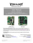
11.1. Dimensions
Main Unit & Surface Mount Bracket
Doc # INS 20Z704T-PZ10
Revision: B
Ceiling Mount Bracket
Issue Date: 08/13/2009
Page 39 of 40
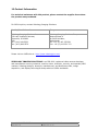
12.Contact Information
For technical assistance with this product, please contact the supplier from whom
the product was purchased.
For OEM inquiries, contact Videology Imaging Solutions:
North / South America:
Europe:
Videology Imaging Solutions Inc.
37M Lark Industrial Parkway
Greenville, RI 02828
USA
Tel: (401) 949-5332
Fax: (401) 949-5276
Videology Imaging Solutions Europe
Neutronenlaan 4
NL-5405 NH Uden,
Netherlands
Tel: +31 (0) 413 256 261
Fax: +31 (0) 413 251 712
Please visit our WEB-site at: http://www.videologyinc.com/
VIDEOLOGY IMAGING SOLUTIONS is an ISO 9001 registered video camera developer
and manufacturer serving industrial, machine vision, biometric, security, and specialty OEM
markets. Videology designs, develops, manufactures, and distributes video, image
acquisition, and display technologies and products to OEMs worldwide.
Doc # INS 20Z704T-PZ10
Revision: B
Issue Date: 08/13/2009
Page 40 of 40