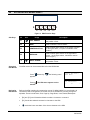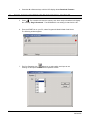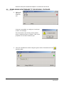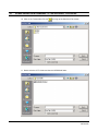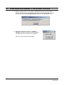
1
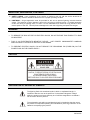
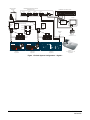
MXSYS04E Ethernet System Controller USER MANUAL MXMU000633 29/June/02 ISSUE DATE 1 14 July 2002 REVISIONS Preliminary release. . 2001 BY ULTRAK ALL RIGHTS RESERVED ULTRAK CORPORATE OFFICE 1301 WATERS RIDGE DRIVE LEWISVILLE, TX 75057 (972) 353-6500 www.ultrak.com ALL RIGHTS RESERVED. NO PART OF THIS PUBLICATION MAY BE REPRODUCED BY ANY MEANS WITHOUT WRITTEN PERMISSION FROM ULTRAK. THE INFORMATION IN THIS PUBLICATION IS BELIEVED TO BE ACCURATE IN ALL RESPECTS. HOWEVER, ULTRAK CANNOT ASSUME RESPONSIBILITY FOR ANY CONSEQUENCES RESULTING FROM THE USE THEREOF. THE INFORMATION CONTAINED HEREIN IS SUBJECT TO CHANGE WITHOUT NOTICE. REVISIONS OR NEW EDITIONS TO THIS PUBLICATION MAY BE ISSUED TO INCORPORATE SUCH CHANGES. REVXA ii MXMU000633 29/June/02 FCC COMPLIANCE STATEMENT INFORMATION TO THE USER: THIS EQUIPMENT HAS BEEN TESTED AND FOUND TO COMPLY WITH THE LIMITS FOR A CLASS A DIGITAL DEVICE, PURSUANT TO PART 15 OF THE FCC RULES. THESE LIMITS ARE DESIGNED TO PROVIDE REASONABLE PROTECTION AGAINST HARMFUL INTERFERENCE WHEN THE EQUIPMENT IS OPERATED IN A COMMERCIAL ENVIRONMENT. THIS EQUIPMENT GENERATES, USES, AND CAN RADIATE RADIO FREQUENCY ENERGY AND, IF NOT INSTALLED AND USED IN ACCORDANCE WITH THE INSTRUCTION MANUAL, MAY CAUSE HARMFUL INTERFERENCE TO RADIO COMMUNICATIONS. OPERATION OF THIS EQUIPMENT IN A RESIDENTIAL AREA IS LIKELY TO CAUSE HARMFUL INTERFERENCE IN WHICH CASE THE USER WILL BE REQUIRED TO CORRECT THE INTERFERENCE AT HIS OWN EXPENSE. CAUTION: CHANGES OR MODIFICATIONS NOT EXPRESSLY APPROVED BY THE PARTY RESPONSIBLE FOR COMPLIANCE COULD VOID THE USER’S AUTHORITY TO OPERATE THE EQUIPMENT. THIS CLASS A DIGITAL APPARATUS COMPLIES WITH CANADIAN ICES-003. CET APPAREIL NUMÉRIQUE DE LA CLASSE A EST CONFORME À LA NORME NMB-003 DU CANADA. REVXA iii MXMU000633 29/June/02 DECLARATION OF CONFORMITY To The European Community Council Directive 89/336/EEC ISSUED BY: ® Ultrak , Inc. 4465 Coonpath Road NW Carroll, OH 43112 USA Tel: (740) 756-9222 Fax: (740) 756-4237 ® MANUFACTURER: Ultrak , Inc. DATE OF ISSUE: May 23, 2002 TYPE OF EQUIPMENT: CCTV and Security Surveillance Equipment MODEL NUMBER: Alarm Interface Unit AIU-100 - may be followed by any number of alphanumeric characters. Auxiliary Interface Units* AIF-100/CO Central Control Unit CCU-100 - may be followed by any number of alphanumeric characters. CCU-150 – may be followed by any number of alphanumeric characters. CCU-200 – may be followed by any number of alphanumeric characters. Joystick Multiplexer MUX-100 – may be followed by any number of alphanumeric characters MUX-05 – may be followed by any number of alphanumeric characters Joystick Controller* JPD-100, JPD-101, JPD-200 - may be followed by any number of alphanumeric characters. KEGS5000 Small System Interface* MXSYS04E Video Matrix* SSI-100 - may be followed by any number of alphanumeric characters. Control Output Expander* COE-08, COE-16 - may be followed by any number of alphanumeric characters Control Receiver CRX-610/BX, CRX-801AX, CRX-801BX Control Transmitter* UCT-10 – may be followed by any number of alphanumeric characters. UltraKey* KEGSA – may be followed by any number of alphanumeric characters. *Standard EN60065 does not apply. STANDARDS TO WHICH CONFORMITY IS DECLARED: EN50081-1 Emissions Standard, and EN50082-1 Immunity Standard. EN55022 Radiated, Class A, EN55022 Conducted, Class A, IEC-1000-4-2, ESD, IEC-1000-4-3, RF Fields, IEC-1000-4-4, Fast Transients/Burst. EN60065 Safety Requirements for Mains Operated Electronic and Related Apparatus for Household and Similar General Use ® Ultrak , Inc. hereby declares that the models specified above conform to the directive and standard as specified. Donald L. Stephenson Compliance Engineer 517775-3 REVXA Rev. R iv October 2, 2001 MXMU000633 29/June/02 IMPORTANT SAFEGUARDS 1. READ AND FOLLOW INSTRUCTIONS – All of the safety and operating instructions should be read before the appliance is operated and followed during installation and operation.. 2. RETAIN INSTRUCTIONS – The safety and operating instructions should be retained for future reference. 3. HEED WARNINGS – All warnings on the product and in the operating instructions should be adhered to. 4. CLEANING – I Unplug the unit from the outlet before cleaning. Do not use liquid cleaners or aerosol cleaners. Use a damp cloth for cleaning. See cleaning procedures under Maintenance. 5. OBJECT AND LIQUID ENTRY – Never push objects of any kind into this equipment as they may touch dangerous voltage points or short-out parts that could result in a fire or electric shock. Never spill liquid of any kind on the product. 6. ACCESSORIES – Do not place this unit on an unstable stand, tripod, bracket, or mount. The unit may fall, causing serious injury to a person and serious damage to the unit. Use only with a stand, tripod, bracket, or mount recommended by the manufacturer, or sold with the product. Any mounting of the unit should follow the manufacturer’s instructions, and should use a mounting accessory recommended by the manufacturer. 7. WATER AND MOISTURE – Do not use this product near water. 8. POWER SOURCES – This unit should be operated only from the type of power source indicated on the marking label. 9. GROUNDING OR POLARIZATION – This unit must be connected to a true Earth ground. This product is equipped with a 3-wire grounding type plug; a plug having a third (grounding) pin. This plug will only fit into a grounding-type power outlet. This is a safety feature. If you are unable to insert the plug into the outlet, contact your electrician to replace your obsolete outlet. Do not defeat the safety purpose of the groundingtype plug. 10. OVERLOADING – Do not overload outlets and extension cords as this can result in a risk of fire or electric shock. 11. POWER CORD PROTECTION – Power supply cords should be routed so they will not be walked on or pinched by items placed on or against them. Pay particular attention to the cord at the electrical outlet and the point where the plug connects to the product. 12. SERVICING – Do not attempt to service this unit yourself as opening or removing covers may expose you to dangerous voltage or other hazards. Refer all servicing to qualified service personnel. Caution: Grounded wrist straps must be worn and proper ESD safety precautions observed when handling the electrostatic-sensitive printed circuit boards. 13. DAMAGE REQUIRING SERVICE – Remove power to the unit and refer servicing to qualified service personnel under the following conditions: a. If liquid has been spilled, or objects have fallen into the unit. b. If the unit does not operate normally by following the operating instructions. Adjust only those controls that are covered by the operating instructions as an improper adjustment of other controls may result in damage and will often require extensive work by a qualified technician to restore the unit to its normal operation. c. If the unit has been dropped or the enclosure has been damaged. d. When the unit exhibits a distinct change in performance - this indicates a need for service. 14. REPLACEMENT PARTS – When replacement parts are required, be sure the service technician has used replacement parts specified by the manufacturer or have the same characteristics as the original part. Unauthorized substitutions may result in fire, electric shock or other hazards. REVXA v MXMU000633 29/June/02 IMPORTANT SAFEGUARDS, CONTINUED 15. SAFETY CHECK - Upon completion of any service or repairs to this unit, ask the service technician to perform safety checks to determine that the unit is in proper operating condition. 16. LIGHTNING – Surge suppression must be provided for this unit to prevent lightning induced electrical surges. The warranty is void if damage is done to the unit due to electrical surges. For added protection of this unit during a lightning storm, or when it is left unattended and unused for long periods of time, remove power to the unit. This will prevent damage to the unit due to lightning and power-line surges. WARNING • TO REDUCE THE RISK OF FIRE OR ELECTRIC SHOCK, DO NOT EXPOSE THIS PRODUCT TO RAIN OR MOISTURE. • THIS IS AN ELECTROSTATIC-SENSITIVE DEVICE. USE PROPER CMOS/MOSFET HANDLING PRECAUTIONS TO AVOID ELECTROSTATIC DISCHARGE. • TO PREVENT ELECTRIC SHOCK, DO NOT REMOVE THE GROUNDING PIN (THIRD PIN) ON THE POWER PLUG ON THE POWER SUPPLY. CAUTION CAUTION RISK OF ELECTRIC SHOCK DO NOT OPEN CAUTION: TO REDUCE THE RISK OF ELECTRIC SHOCK, DO NOT REMOVE COVER (OR BACK). NO USER-SERVICEABLE PARTS INSIDE. REFER SERVICING TO QUALIFIED SERVICE PERSONNEL. EXPLANATION OF GRAPHICAL SYMBOLS The lightning flash with arrowhead symbol, within an equilateral triangle, is intended to alert the user to the presence of uninsulated "dangerous voltage" within the product's enclosure that may be of sufficient magnitude to constitute a risk of electric shock to persons. The exclamation point within an equilateral triangle is intended to alert the user to the presence of important operating and maintenance (servicing) instruction in the literature accompanying the product. REVXA vi MXMU000633 29/June/02 TABLE OF CONTENTS SECTION 1: INTRODUCTION ....................................................................................................................... 1 1.1 PRODUCT DESCRIPTION ................................................................................................................. 1 1.2 FEATURES........................................................................................................................................ 1 SECTION 2: CONNECTIONS ........................................................................................................................ 2 2.1 CONNECTIONS ................................................................................................................................. 2 MXSYS04E PORT CONNECTIONS .................................................................................................... 3 SECTION 3: INSTALLATION AND SETUP ..................................................................................................... 4 3.1 INSTALLATION DIAGRAMS ............................................................................................................... 4 3.2 SELECTING DEFAULT CONFIGURATIONS ..................................................................................... 10 Selecting defaults through the setup menus. ...................................................................................... 10 Setting defaults without the use of a keyboard .................................................................................... 10 MX-32128 Default............................................................................................................................. 10 MX-32128 Hybrid Default .................................................................................................................. 10 MX-1132 Default............................................................................................................................... 11 MX-1132 Hybrid Default.................................................................................................................... 11 Digital 1 Default ................................................................................................................................ 12 Digital 2 Default ................................................................................................................................ 12 3.3 KD6 SETUP ..................................................................................................................................... 13 KD6 Setup ....................................................................................................................................... 13 3.5 KEGS5000 SETUP ........................................................................................................................... 13 Check Compatibility of the KEGS5000 Firmware ................................................................................ 13 Selecting the correct KEGS5000 Firmware......................................................................................... 13 Changing the Address of the KEGS5000............................................................................................ 14 SECTION 4: OPERATION WITH A KEGS5000.............................................................................................. 15 4.1 LOGGING INTO THE SYSTEM......................................................................................................... 15 Booting the System........................................................................................................................... 15 Logging into the System.................................................................................................................... 15 Logging Out the System.................................................................................................................... 15 Default Passwords............................................................................................................................ 15 Operator Default Rights .................................................................................................................... 15 4.2 CONTROLLING MONITORS AND CAMERAS ................................................................................... 16 Selecting a Monitor ........................................................................................................................... 16 Selecting a Camera .......................................................................................................................... 16 4.3 PTZ OPERATION............................................................................................................................. 17 View/ Preshot Save........................................................................................................................... 17 View/ Preshot Recall......................................................................................................................... 17 Control of the KD6 through preshots .................................................................................................. 17 4.4 ACCESSING KD6 MENUS DIRECT.................................................................................................. 18 Soft Keys ......................................................................................................................................... 18 Accessing KD6 Menus ...................................................................................................................... 18 Navigating KD6 menus ..................................................................................................................... 18 4.5 ALTERNATE CAMERA AND PTZ CALL ............................................................................................ 19 Alternate Camera ............................................................................................................................. 19 PTZ Call........................................................................................................................................... 19 REVXA vii MXMU000633 29/June/02 4.6 SEQUENCES................................................................................................................................... 20 Running a Sequence ........................................................................................................................ 20 Default Sequences ........................................................................................................................... 20 Pausing a Sequence by moving the Joystick...................................................................................... 20 Controlling the Sequence Manually.................................................................................................... 21 Pausing and Resuming the Sequence................................................................................................ 21 Stopping a Sequence........................................................................................................................ 21 Exiting the Sequence Menu............................................................................................................... 21 4.7 ALARMS.......................................................................................................................................... 22 Accepting an Alarm........................................................................................................................... 22 Sequencing of Alarms....................................................................................................................... 22 Clearing an Alarm............................................................................................................................. 22 SECTION 5: PROGRAMMING...................................................................................................................... 23 5.1 NAVIGATING THE SETUP MENUS USING A KEGS5000.................................................................. 23 Enter Setup Mode............................................................................................................................. 23 Navigating the Menus ....................................................................................................................... 23 Editing Menus .................................................................................................................................. 24 5.2 SETTING THE TIME AND DATE ....................................................................................................... 24 5.3 SETTING CAMERA TITLES.............................................................................................................. 25 5.4 SETTING UP KDZ DOMES............................................................................................................... 26 Changing the PTZ Type from a KD6 to a KDZ.................................................................................... 26 Programming the address of the KDZ................................................................................................ 26 5.5 SAVING CHANGES.......................................................................................................................... 27 5.6 PROGRAMMING SEQUENCES........................................................................................................ 27 SECTION 6 UPDATING FIRMWARE ............................................................................................................ 29 6.1 DOWNLOADING NEW FIRMWARE TO THE KEGS5000.................................................................... 29 6.2 DOWNLOADING NEW FIRMWARE TO THE MXSYS04E................................................................... 34 Download files from website.............................................................................................................. 34 SETTING UP THE RFU DOWNLOAD PROGRAM.............................................................................. 34 DOWNLOADING A MXSYS04E BIN FILE TO THE MXSYS04E or MXSYS04E .................................... 35 SECTION 7: TROUBLESHOOTING AND MAINTENANCE ............................................................................ 37 7.1 TROUBLESHOOTING ...................................................................................................................... 37 7.2 PREVENTIVE MAINTENANCE ......................................................................................................... 37 SECTION 7: SPECIFICATIONS .................................................................................................................... 39 CONTACT NUMBERS ULTRAK OFFICES WORLDWIDE ............................................................................. 40 US SALES OFFICES.............................................................................................................................. 40 INTERNATIONAL OFFICES.................................................................................................................... 40 LIST OF FIGURES Figure 1: .Connections of the MXSYS04E ........................................................................................................ 2 Figure 2: MXSYS04E CONNECTIONS ........................................................................................................... 3 Figure 3: Default System Configuration – MX-32128 ......................................................................................... 4 REVXA viii MXMU000633 29/June/02 Figure Figure Figure Figure Figure Figure 4: 5: 6: 7: 8: 9: REVXA Default System Configuration – MX-32128 Hybrid.............................................................................. 5 Default System Configuration – MX-1132.......................................................................................... 6 Default System Configuration – MX-1132 Hybrid ............................................................................... 7 Default System Configuration – Digital 1 ............................................................................................ 8 Default System Configuration – Digital 2 ............................................................................................ 9 KD6 Function Keys........................................................................................................................ 18 ix MXMU000633 29/June/02 SECTION 1: INTRODUCTION 1.1 PRODUCT DESCRIPTION The MXSYS04E is a system controller designed to take advantage of the flexibility of the Maxpro range of hardware as well as integrate Ultraks’ latest range of digital products. The controller supports the Maxpro MX-32128 HD series subracks as well as the MX-1132 subracks with any combination of Maxpro cards. The MXSYS04E has 4 serial ports which can be software configured as RS-232, RS-485 or RS-422. The protocol used on each port is also software defined. The control software is powerful and flexible and includes PTZ control, Multiple keyboards with priority levels, flexible alarm handling, sequences, timed events and a powerful, yet simple, macro language A 10 base T Ethernet port provides TCP/IP connection with the KEGS002’s (Ultrakeys). The Ethernet also allows the matrix to control Ultrak’s range of digital products providing a true hybrid analog/digital solution. Firmware is uploaded from a PC making service and software upgrades simple. Configuration data can be uploaded or downloaded from the unit. The MXSYS04E is powered by an external, universal power supply. The MXSYS04E can be placed on a desk or 19” rack mounted using the brackets provided. 1.2 FEATURES The MXSYS04E controller includes the following features: REVXA • Full control of a fully loaded MX-32128 • 32 Titled Composite Video Outputs – MX-32128 • 32 Potential Free Alarm Inputs - MX-32128 • Control of up to 128 Ultrak domes - MX-32128 • 8 Open Collector Alarm Outputs – MX-32128 • Support for 8 keyboards (KEGS5000, KEGS5300 and KEGS002) • User programmable macros • Separate logins for Operators and Master Users (supervisors) • Sequences and Tours • Support for Ultrak’s digital range of products through the Ethernet connection 1 MXMU000633 29/June/02 SECTION 2: CONNECTIONS 9 2.1 8 7 6 5 4 3 2 1 CONNECTIONS Figure 1: .Connections of the MXSYS04E ID REVXA Usage Description 1 Power Power Connector – Direct from MXPS9. 2 Power Power Connector – From 9-12VDC Power Supply 3 Ethernet Port 10 Base T Ethernet Port 4 Down Load Port RS-232 Connection to PC for Firmware Downloads 5 Reset System Reset 6 Port 1 RS-232 \ RS-485 Serial Port 1 7 Port 2 RS-232 \ RS-485 Serial Port 2 8 Port 3 RS-232 \ RS-485 Serial Port 3 9 Port 4 RS-232 \ RS-485 Serial Port 4 2 MXMU000633 29/June/02 Figure 2: MXSYS04E CONNECTIONS 1 6 Looking into the Socket MXSYS04E PORT CONNECTIONS RS-323 RS-485 RS-422 SUBRACK CONNECTOR PORT 1,2,3,4 PIN 3, TX PIN 4, GND PIN 5, RX PIN 3, DPIN 4, GND PIN 5, D+ PIN 1, RX+ PIN 2, RX PIN 3, TXPIN 4, GND PIN 5, TX+ KEGS5300 CONNECTOR PORT 1,2,3,4 PIN 1, +9V PIN 3, TX PIN 4, GND PIN 5, RX PIN 6, GND PIN 1, +9V PIN 3, DPIN 4, GND PIN 5, D+ PIN 6, GND PIN 1, +9V PIN 3, TXPIN 4, GND PIN 5, TX+ PIN 6, GND KEGS5000 CONNECTOR PORT 1,2,3,4 PIN 2, RX PIN 3, TX PIN 4, +9V PIN 5, GND PIN 2, D+ PIN 3, DPIN 4, +9V PIN 5, GND PIN 2, TX+ PIN 3, TXPIN 4, +9V PIN 5, GND REVXA 3 MXMU000633 29/June/02 SECTION 3: INSTALLATION AND SETUP 3.1 INSTALLATION DIAGRAMS RS-485 PTZ Data 1 - PTZ 1-16 Alarm Inputs 1-8 PTZ ADDRESSES PTZ 1 -16: address 1-16, Port 1 PTZ Data 1 - PTZ 16-32 Alarm Inputs 9-16 PTZ Data 1 - PTZ 32-48 Alarm Inputs 17-24 24 N/O Alarm Inputs PTZ 17-32 address 1-16, Port 2 PTZ 33-48 address 1-16, Port 3 PTZ 49-64 address 1-16, Port 4 PTZ Data 1 - PTZ 49-64 PTZ 65-80 address 1-16, Port 5 PTZ 81-96 address 1-16, Port 6 PTZ Data 1 - PTZ 65-80 Alarm Outputs 1-8 8 N/O Relay Outputs PTZ 97-112 address 1-16, Port 7 PTZ Data 1 - PTZ 81-96 PTZ 113-128 address 1-16, Port 8 PTZ Data 1 - PTZ 97-112 PTZ Data 1 - PTZ 113-128 Output 1 Input 1 Monitor 1 RS-485 PTZ 1 128 Video Inputs 16 Video Outputs with Title / Time /Date Input 128 Output 16 Monitor 16 Flat ribbon cable - cross over PTZ 128 MX32128 HD SUBRACK Address 1 Flat ribbon cable cross over MXSYS04E Ethernet System Controller IP Address 10.5.1.80 Port 4 Port 3 Port 2 Port 1 Ultrak # RE-RTD12/5RT RS-485 PSU 12 VDC 500 mA + RS-485 Ultrak # RE-RTD12/5RT +12VDC RS-485 (D-) - RS-232 (RX) RS-485 (D+) RS-485 (D-) KEGS5000SystemController KEGS5000 - 1 Address 1 Keyboard 2 + RS-485 (D+) GND RS-232 (TX) RS-232 (RX) RS-232 (TX) GND +12VDC Flat Ribbon cable Crossover PSU 12 VDC 500 mA - Ethernet Crossover Cable RS-232 (RX) RS-485 (D+) RS-485 (D-) KEGS5000 System Controller KEGS5000 - 2 Address 2 Keyboard 3 KEGS5300 - 1 Address 3 Keyboard 4 Ultrakey -1 IP Address 10.5.1.81 Keyboard 1 Figure 3: Default System Configuration – MX-32128 REVXA 4 MXMU000633 29/June/02 3.1 INSTALLATION DIAGRAMS, CONTINUED RS-485 PTZ Data 1 - PTZ 1-16 Alarm Inputs 1-8 PTZ Data 1 - PTZ 16-32 Alarm Inputs 9-16 PTZ Data 1 - PTZ 32-48 Alarm Inputs 17-24 PTZ ADDRESSES PTZ 1 -16: address 1-16, Port 1 24 N/O Alarm Inputs PTZ 17-32 address 1-16, Port 2 PTZ 33-48 address 1-16, Port 3 PTZ 49-64 address 1-16, Port 4 PTZ Data 1 - PTZ 49-64 PTZ 65-80 address 1-16, Port 5 PTZ 81-96 address 1-16, Port 6 PTZ Data 1 - PTZ 65-80 Alarm Outputs 1-8 8 N/O Relay Outputs PTZ 97-112 address 1-16, Port 7 PTZ Data 1 - PTZ 81-96 PTZ 113-128 address 1-16, Port 8 PTZ Data 1 - PTZ 97-112 PTZ Data 1 - PTZ 113-128 Output 1 Input 1 Monitor 1 RS-485 PTZ 1 128 Video Inputs 16 Video Outputs with Title / Time /Date Input 128 Output 16 Monitor 16 Flat ribbon cable - cross over PTZ 127 MX32128 HD SUBRACK Address 1 Flat ribbon cable cross over MXSYS04E Ethernet System Controller IP Address 10.5.1.80 Port 4 Port 3 Port 2 ETHERNET 10/100 Base T Switch Port 1 Monitor 17 KN6000DU Client IP Address 10.5.1.10 Ultrak # RE-RTD12/5RT RS-485 PSU 12 VDC 500 mA + RS-485 Ultrak # RE-RTD12/5RT +12VDC RS-485 (D-) PSU 12 VDC 500 mA - + RS-485 (D+) GND RS-232 (TX) RS-232 (RX) - Flat Ribbon cable Crossover Ethernet Cable Camera 128 KD6-Digital IP Address 10.5.1.100 RS-232 (RX) RS-485 (D+) RS-485 (D-) KEGS5000SystemController KEGS5000 - 1 Address 1 Keyboard 2 RS-232 (TX) GND +12VDC RS-232 (RX) RS-485 (D+) RS-485 (D-) KEGS5000 System Controller KEGS5000 - 2 Address 2 Keyboard 3 KEGS5300 - 1 Address 3 Keyboard 4 Ultrakey -1 IP Address 10.5.1.81 Keyboard 1 Figure 4: Default System Configuration – MX-32128 Hybrid REVXA 5 MXMU000633 29/June/02 MX-440 8 Output Alarm Card Slot 16 Alarm Outputs 1-8 RD-316 PTZ Control Card Slot 12 MX-400 8 Input Alarm Card Slot 15 N/O Alarm Inputs 9-16 RD-316 PTZ Control Card Slot 13 MX-400 8 Input Alarm Card Slot 14 N/O Alarm Inputs 1-8 RD-85 32 x 1 Video Switch Card Slot 9 MX-205 Video Text Card Slot 10 RD-85 32 x 1 Video Switch Card Slot 7 MX-205 Video Text Card Slot 8 RD-85 32 x 1 Video Switch Card Slot 5 MX-205 Video Text Card Slot 6 RD-85 32 x 1 Video Switch Card Slot 3 MX-205 Video Text Card Slot 4 RD-85 32 x 1 Video Switch Card Slot 1 MX-205 Video Text Card Slot 2 MX32128 HD SUBRACK Address 1 PTZ 1 Address 1 RS-485 PTZ 16 Address 16 RS-485 PTZ 17 Address 1 Flat ribbon cable - cross over Monitor 5 Monitor 1 RD-105 CPU - Slot 0 PTZ 32 Address 16 Flat ribbon cable cross over MXSYS04E Ethernet System Controller IP Address 10.5.1.80 Port 4 Port 3 Port 2 Port 1 Ultrak # RE-RTD12/5RT RS-485 PSU 12 VDC 500 mA + +12VDC RS-485 (D-) PSU 12 VDC 500 mA - RS-232 (RX) RS-485 (D+) RS-485 (D-) KEGS5000SystemController KEGS5000 - 1 Address 1 Keyboard 2 Flat Ribbon cable Crossover RS-485 Ultrak # RE-RTD12/5RT + RS-485 (D+) GND RS-232 (TX) RS-232 (RX) RS-232 (TX) GND +12VDC - Ethernet Crossover Cable RS-232 (RX) RS-485 (D+) RS-485 (D-) KEGS5000 System Controller KEGS5000 - 2 Address 2 Keyboard 3 KEGS5300 - 1 Address 3 Keyboard 4 Ultrakey -1 IP Address 10.5.1.81 Keyboard 1 Figure 5: Default System Configuration – MX-1132 REVXA 6 MXMU000633 29/June/02 MX-440 8 Output Alarm Card Slot 16 Alarm Outputs 1-8 RD-316 PTZ Control Card Slot 12 MX-400 8 Input Alarm Card Slot 15 N/O Alarm Inputs 9-16 RD-316 PTZ Control Card Slot 13 MX-400 8 Input Alarm Card Slot 14 N/O Alarm Inputs 1-8 RD-85 32 x 1 Video Switch Card Slot 9 MX-205 Video Text Card Slot 10 RD-85 32 x 1 Video Switch Card Slot 7 MX-205 Video Text Card Slot 8 RD-85 32 x 1 Video Switch Card Slot 5 MX-205 Video Text Card Slot 6 RD-85 32 x 1 Video Switch Card Slot 3 MX-205 Video Text Card Slot 4 RD-85 32 x 1 Video Switch Card Slot 1 MX-205 Video Text Card Slot 2 MX32128 HD SUBRACK Address 1 PTZ 1 Address 1 RS-485 PTZ 16 Address 16 RS-485 PTZ 17 Address 1 Flat ribbon cable - cross over Monitor 5 Monitor 1 RD-105 CPU - Slot 0 PTZ 32 Address 16 Flat ribbon cable cross over MXSYS04E Ethernet System Controller IP Address 10.5.1.80 Port 4 Port 3 Port 2 ETHERNET 10/100 Base T Switch Port 1 Monitor 6 KN6000DU Client IP Address 10.5.1.10 Ultrak # RE-RTD12/5RT RS-485 PSU 12 VDC 500 mA + RS-485 Ultrak # RE-RTD12/5RT +12VDC RS-485 (D-) PSU 12 VDC 500 mA - + RS-485 (D+) GND RS-232 (TX) RS-232 (RX) - Flat Ribbon cable Crossover Ethernet Cable Camera 33 KD6-Digital IP Address 10.5.1.100 RS-232 (RX) RS-485 (D+) RS-485 (D-) KEGS5000SystemController KEGS5000 - 1 Address 1 Keyboard 2 RS-232 (TX) GND +12VDC RS-232 (RX) RS-485 (D+) RS-485 (D-) KEGS5000 System Controller KEGS5000 - 2 Address 2 Keyboard 3 KEGS5300 - 1 Address 3 Keyboard 4 Ultrakey -1 IP Address 10.5.1.81 Keyboard 1 Figure 6: Default System Configuration – MX-1132 Hybrid REVXA 7 MXMU000633 29/June/02 Flat ribbon cable cross over MXSYS04E Ethernet System Controller IP Address 10.5.1.80 Port 4 Port 3 Port 2 ETHERNET 10/100 Base T Switch Port 1 Monitor 1 KN6000DU Client IP Address 10.5.1.10 Ultrak # RE-RTD12/5RT RS-485 PSU 12 VDC 500 mA + RS-485 Ultrak # RE-RTD12/5RT +12VDC RS-485 (D-) PSU 12 VDC 500 mA - + RS-485 (D+) GND RS-232 (TX) RS-232 (RX) - Ethernet Cable Camera 1 KD6-Digital IP Address 10.5.1.100 RS-232 (RX) RS-485 (D+) RS-485 (D-) KEGS5000SystemController KEGS5000 - 1 Address 1 Keyboard 2 RS-232 (TX) GND +12VDC RS-232 (RX) RS-485 (D+) RS-485 (D-) KEGS5000 System Controller KEGS5000 - 2 Address 2 Keyboard 3 KEGS5300 - 1 Address 3 Keyboard 4 Ultrakey -1 IP Address 10.5.1.81 Keyboard 1 Figure 7: Default System Configuration – Digital 1 REVXA 8 MXMU000633 29/June/02 RS-485 Camera 1 KD6-Dome Address 1 Input 1 Camera 2 KD6-Dome Address 2 Input 2 Input 3 Input 4 KN6000DU Server IP Address 10.5.1.100 Camera 3 KD6-Dome Address 3 Camera 4 KD6-Dome Address4 Flat ribbon cable cross over MXSYS04E Ethernet System Controller IP Address 10.5.1.80 Port 4 Port 3 Port 2 ETHERNET 10/100 Base T Switch Port 1 Monitor 1 KN6000DU Client IP Address 10.5.1.10 Ultrak # RE-RTD12/5RT RS-485 PSU 12 VDC 500 mA + RS-485 Ultrak # RE-RTD12/5RT +12VDC RS-485 (D-) PSU 12 VDC 500 mA - + RS-485 (D+) GND RS-232 (TX) RS-232 (RX) - Ethernet Cable RS-232 (RX) RS-485 (D+) RS-485 (D-) KEGS5000SystemController KEGS5000 - 1 Address 1 Keyboard 2 RS-232 (TX) GND +12VDC RS-232 (RX) RS-485 (D+) RS-485 (D-) KEGS5000 System Controller KEGS5000 - 2 Address 2 Keyboard 3 KEGS5300 - 1 Address 3 Keyboard 4 Ultrakey -1 IP Address 10.5.1.81 Keyboard 1 Figure 8: Default System Configuration – Digital 2 REVXA 9 MXMU000633 29/June/02 3.2 SELECTING DEFAULT CONFIGURATIONS Selecting defaults through the setup menus. Setting defaults without the use of a keyboard The MXSYS04E has a number of default configurations pre-programmed. These can be recalled from the setup menu 14: Erase Settings to defaults. The Defaults are as in the above system diagrams. Select the required default and press Enter. Use the jogwheel to select Yes. Press Enter to accept this. The MXSYS04E will now erase all previous settings and reboot with the new configuration. The default configurations can also be set by simply pressing the reset button a predetermined number of times. Apply power to the MXSYS04E. Press the reset button the number of times indicated below to erase all settings and configuration and preset the unit for the default systems below. WARNING: ALL CONFIGURATION DATA WILL BE LOST MX-32128 Default After applying power press the reset button 5 times at a rate of 1 press a second. Figure 3 Default System Configuration MX-32128 shows the MXSYS04E controlling a MX32128 Maxpro HD Subrack. This configuration has the following features MX-32128 Hybrid Default • 128 Camera Inputs • 128 PTZ control • 16 Titled Monitor Outputs • 1 Ultrakey • 2 KEGS5000 Keyboards • 1 KEGS5300 Keyboard • 24 Alarm Input • 8 Alarm Outputs • 24 Pre configured Events • 32 Pre configured Sequences After applying power press the reset button 6 times at a rate of 1 press a second Figure 4 Default System Configuration MX-32128 Hybrid shows the MXSYS04E controlling a MX-32128 Maxpro HD Subrack and integrating a Digital Dome with a Digital Monitor. This configuration has the following features. • REVXA 127 Analog Camera Inputs 10 MXMU000633 29/June/02 MX-1132 Default • 1 Digital Camera Input • 128 PTZ control • 16 AnalogTitled Monitor Outputs • 1 Digital Monitor Output • 1 Ultrakey • 2 KEGS5000 Keyboards • 1 KEGS5300 Keyboard • 24 Alarm Input • 8 Alarm Outputs • 24 Pre configured Events • 32 Pre configured Sequences After applying power press the reset button 7 times at a rate of 1 press a second Figure 5 Default System Configuration MX-1132 shows the MXSYS04E controlling a MX-1132 Maxpro Subrack. This configuration has the following features. MX-1132 Hybrid Default • 32 Analog Camera Inputs • 32 PTZ control • 5 AnalogTitled Monitor Outputs • 1 Ultrakey • 2 KEGS5000 Keyboards • 1 KEGS5300 Keyboard • 16 Alarm Inputs • 8 Alarm Outputs • 16 Pre configured Events • 32 Pre configured Sequences After applying power press the reset button 8 times at a rate of 1 press a second Figure 6 Default System Configuration MX-1132 Hybrid shows the MXSYS04E controlling a MX-1132 Maxpro Subrack and integrating a Digital Dome with a Digital Monitor. This configuration has the following features. • REVXA 32 Analog Camera Inputs 11 MXMU000633 29/June/02 Digital 1 Default • 1 Digital Camera Input • 32 PTZ control • 5 AnalogTitled Monitor Outputs • 1 Digital Monitor Output • 1 Ultrakey • 2 KEGS5000 Keyboards • 1 KEGS5300 Keyboard • 16 Alarm Input • 8 Alarm Outputs • 16 Pre configured Events • 8 Pre configured Sequences After applying power press the reset button 9 times at a rate of 1 press a second Figure 7 Default System Configuration Digital shows the MXSYS04E controlling a Digital Dome with a Digital Monitor. This configuration has the following features. Digital 2 Default • 1 Digital Camera Input • 1 PTZ control • 1 Digital Monitor Output • 1 Ultrakey • 2 KEGS5000 Keyboards • 1 KEGS5300 Keyboard After applying power press the reset button 10 times at a rate of 1 press a second Figure 8 Default System Configuration Digital shows the MXSYS04E controlling a KN6000DU Digital Dome with a Digital Monitor. This configuration has the following features. REVXA • 4 Switched Digital Camera Inputs • 4 PTZ control • 1 Digital Monitor Output • 1 Ultrakey • 2 KEGS5000 Keyboards 12 MXMU000633 29/June/02 • 3.3 1 KEGS5300 Keyboard KD6 SETUP KD6 Setup The KD6 Dome must be set to operate in the Maxpro mode. DIP switch S4 must be set as follows. S4-1 ON S4-2 OFF S4-3 OFF S4-4 OFF Refer to page 4 of the Ultradome KD6 Operation and Programming manual (Ref 518584-2960) for more details. The address of the KD6 and KD6Z dome must be set to match the number of the camera. Camera 1 – address 1, Camera 2 – address 2 etc 3.5 KEGS5000 SETUP The KEGS5000 must have the correct firmware loaded to work with the MXSYS04E. Check Compatibility of the KEGS5000 Firmware Switch the power off and on again. Make a note of the version of the boot Manager then after the 5 second count down make a note of the KEGS5000 Firmware version. If the boot manager is Version 1.63 or higher then the KEGS5000 will contain a version of the firmware supporting the MXSYS04E. Proceed to SELECTING KEGS5000 FIRMWARE. KEGS5000 with boot manager versions older than Version 1.63 will only contain the standalone firmware. The correct firmware will have to be loaded into the controller. Download the latest version from the Download section on the Ultrak website www.ultrak.com. Refer to the KEGS5000 owner manual for instructions on updating this firmware. Selecting the correct KEGS5000 Firmware KEGS5000 controllers containing a Boot Manager version of 1.63 or higher will have two versions of the controller firmware loaded. 1 KEGS5000 Slave Version 02.00.23 or higher 2- KEGS5000 standalone Version 01.03.05 or higher To work with the MXSYS04E the keyboard must be in the Slave Mode. REVXA 13 MXMU000633 29/June/02 Reboot the KEGS5000 by cycling the power. Before the Boot Count down reaches zero. Press the [1] key Enter the password 1994. The display displays “Run Bank” on the top line and either “Standalone” or “Slave Mode” on the bottom line. Use the [F1] and [F5] keys to select between the two versions and select “Slave Mode”. Press to accept the Slave Mode. The keyboard will then display the version number, the address and then run. Note: The controller remembers which mode it is in and will always power up in the slave mode Changing the Address of the KEGS5000 The default address of the keyboard is set to 1. This is correct for the default configuration for Keyboard 1 when connected to the MXSYS04E. Keyboards 2 –8 will need to be changed to addresses 2 through 8 Reboot the KEGS5000 by cycling the power. Wait for the Boot count down to complete. Press the [F3] key when the Version number is displayed. The current address is displayed. Enter the new address using the numeric keys. Press save the address. to The keyboard display will go blank for a few seconds and then connect to the MXSYS04E REVXA 14 MXMU000633 29/June/02 SECTION 4: OPERATION WITH A KEGS5000 4.1 LOGGING INTO THE SYSTEM Booting the System After connecting powering to the MXSYS04E and the KEGS5000, the LCD display will first show the message “Keyboard is Off Line”. The display then changes to “MXSYS04E VAA Starting ….” Then changes to “System Login Enter PIN:” After connecting power to the MXSYS04E and the KEGS5000, the LCD display will first show the message: Keyboard is Off Line After 20 seconds the display changes to: NOTE: The MXSYS04E takes about 60 seconds to initialize. MXSYS04E VAA Starting….. Before the system can be used, an Operator must login using a password. Enter the password for the operator logging on System Login Enter PIN: Once the correct password has been entered, the Operator is logged in. The display shows which operator is logged in. No Mon. Selected Operator 1 Logging Out the System To change to a different operator or to logout press [F3] (Menu) Sel menu option <ent> to Log out Default Passwords Default Default Default Default Default Operator Default Rights Master Mode has access to all menus. Operator Mode allows access to all menus except those in which changes to system setup are involved. The table below shows which menus and functions are available for each operator by default. Logging into the System Press to log out. password for the Master is 1111 password for Operator 1.is 1231 password for Operator 2 is 1232 password for Operator 3 is 1233 password for Operator 4 is 1234 Description Operators 1-4 Master Preshots 0-9 only Preshots 0 99 0-64 KDZ 0-64 KDZ 0-99 KD6 0-99 KD6 Access to the KD6 Dome menus No Yes Access to the system Setup menu No Yes Save preshot (View) on KD6-Z and KD6 domes Recall Preshot (View) on KD6-Z and KD6 domes REVXA 15 MXMU000633 29/June/02 4.2 CONTROLLING MONITORS AND CAMERAS After logging in the system will not have an active monitor Selecting a Monitor Before a camera can be viewed or controlled a monitor must be active Example: Make monitor 1 the active monitor 1 Selecting a Camera or M1:Camera 1 Operator 1 1 All camera switching will go to the active monitor Example: Switch camera 2 to monitor 1 2 or Note: At anytime pressing the main menu REVXA No Mon. Selected Operator 1 M1:Camera 2 Operator 1 2 key will cancel the current operation and go back to the 16 MXMU000633 29/June/02 4.3 PTZ OPERATION Use the joystick to control the camera. View/ Preshot Save The first 9 preshots (Views) 1-9 are available as scratchpad preshots. These can be saved and recalled by the operator. Preshots (Views) 10-99 -KD6 and 10-64 -KDZ can only be recalled by the operator and not saved. To save a preshot or view, press (VIEW) Example: [number] [F5] 5 [F5] To save view 5, press Note: To save preshots 10-99 you have to log in as a Master User. View/ Preshot Recall To recall a preshot or view, press (VIEW) Example: Control of the KD6 through preshots To recall view 5, press [5] OR OR [number] 5 . . The KD6 can be controlled by recalling preshots. The KD6 must be set for the Maxpro mode as described in the section 3.2 above. The commands available are listed below. Refer to the KD6 owner manual for more details PreShot PreShot PreShot PreShot PreShot PreShot PreShot PreShot PreShot PreShot PreShot PreShot PreShot 80 81 82 83 84 85 86 87 88 89 90 91 92 PreShot 93 PreShot 94 PreShot 95 PreShot 96 PreShot 97-99 REVXA [number] Run PTZ Tour 1 Run PTZ Tour 2 Run PTZ Tour 3 Program PTZ Tour 1 Program PTZ Tour 2 Program PTZ Tour 3 Terminate PTZ Programming Mode Start VectorScan 1 Start VectorScan 2 Start VectorScan 3 Setup the Scan and Camera Toggles the error table display Toggles auto exposure on and off. The factory default is on. Toggles backlight compensation on and off. The unit must be in auto exposure mode for backlight compensation to function. Toggles between standard operation and nightshot mode. (Model CA470S4N, CA470S4P, CA480S4N, and CA480S4P cameras only). Toggles between freeze and unfreeze video Invokes the Flashback Function Reserved 17 MXMU000633 29/June/02 4.4 ACCESSING KD6 MENUS DIRECT F1 F2 F3 F4 F5 Figure 9: KD6 Function Keys Soft Keys ID Usage Description F1 LEFT ARROW Sends the Left command. Used to move the cursor and position of text F2 NEXT Used to select the next character F3 CENTER BUTTON Used to select option shown on the center of screen. (In the figure above, no option is available at this position.) F4 PREVIOUS Used to select option shown on the right side of screen. (In the figure above, it would be used to select Logout.) RIGHT ARROW Sends the Right command. Used to move the cursor and position of text. E Accessing KD6 Menus Icon The KD6 menus can be accessed direct from the KEGS5000. Press followed by appears. Press the following menu . The KD6 menu appears on the Select PTZ Func: Main Menu Sel Character: <A > monitor. Navigating KD6 menus Refer to the KD6 operation & programming manual, 518584-2960-M. for more details. All commands need to navigate the on-screen menus are available by scrolling through the Alphabet. These include Home, End, Page Up, Page Down, Insert, Delete, Backspace • [F2] and [F4] scroll forward and back to select a character or command • [F3] Sends the selected command or character to the KD6 • REVXA sends the lower case letter of the above character to the KD6 18 MXMU000633 29/June/02 • • Numeric keys 0-9 send the corresponding number to the KD6 • [F1] and [F5] send Left and Right commands to the KD6 • : and ? • • 4.5 sends the Esc character to the KD6 send Up and Down commands to the KD6 sends the Enter command to the KD6 exits the KD6 menu on the KEGS5000 ALTERNATE CAMERA AND PTZ CALL Alternate Camera Each camera can have an alternate camera associated with it. Pressing the key will route this camera to the active monitor, by default no alternate cameras are programed. PTZ Call Each camera can have an associated PTZ with corresponding preshot. Press the key to route this camera and recall the associated preshot to the active monitor, by default no alternate cameras are programed. REVXA 19 MXMU000633 29/June/02 4.6 SEQUENCES The MXSYS04E supports up to 32 sequences. Each sequence can contain 32 steps, each step contains the camera number, preshot, transfer time and dwell time. Transfer time is the time taken for the KD6 Dome to move from one preshot to another. Dwell time is the time between each step. Running a Sequence Default Sequences Press the 1 key, use the + and – keys to scroll through the list of sequences. Select Sequence Sequence 1 There are 32 default sequences as listed below. Sequence 1 Sequence 2 Sequence 3 8 Steps, Camera 1 – Camera 8, Dwell of 10 seconds, Preshot 1 on all Cameras 8 Steps, Camera 2 – Camera 9, Dwell of 10 seconds, Preshot 1 on all Cameras 8 Steps, Camera 3 – Camera 10, Dwell of 10 seconds, Preshot 1 on all Cameras Sequence Sequence Sequence Sequence 8 8 8 8 29 30 31 32 Steps, Steps, Steps, Steps, Camera Camera Camera Camera 29 30 31 32 – – – – Camera Camera Camera Camera 4, 5, 6, 7, Dwell Dwell Dwell Dwell of of of of 10 10 10 10 seconds, seconds, seconds, seconds, Press to start the sequence running forward or press the [F5] to run the sequence forward or [F1] to run the sequence backwards The display now changes to show the number of the sequence running in front of the camera name. Preshot Preshot Preshot Preshot 1 1 1 1 on on on on all all all all Cameras Cameras Cameras Cameras M1:S1 Camera 1 Operator 1 M1:S1 Camera 7 Operator 1 The Camera number will now change as the sequence runs. Pausing a Sequence by moving the Joystick REVXA Moving the joystick will automatically pause the sequence. The display will indicate this by displaying Sp in front of the camera number 20 M1:Sp Camera 7 Operator 1 MXMU000633 29/June/02 4.6 SEQUENCES, CONTINUED Controlling the Sequence Manually Press the 1 key to enter the Sequence menu. The top lines shows the sequence number and the current step in the sequence. Press the [F5] key to pause the sequence and step the sequence manually in the forward direction. The display will indicate that the sequence has been paused and display the current step in the sequence. Sequence 1:4 Pause >>> Stop Sequence 1:4 Run Paused Stop Press [F1] to step to the previous step and [F5] to step to the next step. Pausing and Resuming the Sequence Press the 1 key to enter the Sequence menu. The [F2] key will toggle between pausing and running the sequence. The >>>> or <<<< show the direction the sequence is running in Sequence 1:4 Pause >>>> Stop Sequence 1:4 Run Paused Stop Stopping a Sequence Exiting the Sequence Menu REVXA Press the Press 1 to enter the Sequence menu. Press [F4] to stop the sequence running Select Sequence: Sequence 1 To exit the sequence menu press the Clear key M1:Camera 4 Operator 1 21 MXMU000633 29/June/02 4.7 ALARMS By default, alarm inputs are programmed for normally open operation. Closing the contact for Alarm 1 will switch Camera 1 to the Alarm Monitor. By default, this is Monitor 4. The buzzer on the keypad will activate. Accepting an Alarm Sequencing of Alarms Clearing an Alarm REVXA Press the Alarm key to accept the alarm. The buzzer will switch off and the camera will be transferred to the Alarm Accept Monitor. By default this is Monitor 1 Should more than one alarm be triggered before the key is pressed the cameras will sequence on the Alarm Monitor with a 3-second dwell time. The Alarm with the highest priority will be transferred to the Accept Monitor Pressing the key again will clear the Alarm Camera from Monitor 1 and the next alarm will be transferred to Monitor 1 22 MXMU000633 29/June/02 SECTION 5: PROGRAMMING 5.1 NAVIGATING THE SETUP MENUS USING A KEGS5000 Note: To enter the setup mode the user must have rights to do so. By default only the Master user can edit the menus Enter Setup Mode Press [F3] to access setup menus. Navigating the Menus Keys Usage / Description When navigating the root menu, steps to the next menu. PLUS + When editing text, inserts a space after the cursor. When in a menu, used to toggle through any options. When navigating the root menu, steps to the previous menu. MINUS When editing text, deletes the character above the cursor. When in a menu, used to toggle down through any options. When navigating the menus, enters the selected menu. ENTER When editing text, accepts the text and moves to the next menu item. When in a sub menu, accepts the current values and moves to the next menu item. When in the root menu, used to exit out of the programming mode. CLEAR When editing text, used to erase the value to the left of the cursor. When in a sub menu, used to erase the value to the left of the cursor. When the sub menu contains no value, used to exit the sub menu and move up one level. RECORD REVXA When editing a submenu, scrolls through a list of special characters. Use this key to select commas, periods and other special characters. 23 MXMU000633 29/June/02 5.1 NAVIGATING THE SETUP MENUS USING A KEGS5000, CONTINUED Keys Editing Menus 5.2 Usage / Description [F1] Move the cursor left. [F2] Move down through character set. Used to select a character when entering name. [F3] Used to enter the setup mode.and to log an operator out. [F4] Move up through the character set. Used to select a character in a name or value. [F5] Move the cursor right. SETTING THE TIME AND DATE 1. Press [F3] to enter the setup menu 2. Press + until menu 12: Set system time and date is displayed. Press 3. Use the [F1] and [F5] keys to move the cursor to the digit to be changed. Enter the new value using the Sel menu option <ent> to Log out 12:Set system time and Date Ent date (DD/MM/ YYYY):12/03/2002 numerice keys. Press 4. Use the [F1] and [F5] keys to move the cursor to the digit to be changed. Enter the new value using the numeric keys. Press . The system will go back to Ent Time,24h(HH: MM:SS):06:15:25 the Root menu. 5. Press to exit the setup menus. Note: Entering an illegal value will cause the keyboard to beep and jump back to the start of editing the time date. REVXA 24 MXMU000633 29/June/02 5.3 SETTING CAMERA TITLES By default all 32 cameras are named Camera 1 through Camera 32. Camera names can be changed to more meaningful descriptions. 1. Press [F3] to enter the setup menu. 2. Press + Sel menu option <ent> to Log out until the menu 3: Set up Camera Properties is displayed. Press . 3: Set up Camera Properties. 3. Press + and to select the camera to be edited. The [001] shows the camera number followed by the current camera name. Press . Sel. Camera: [001]Camera 1 4. Use the [F1] and [F5] keys to move the cursor to the Edit Camera name Camera 1_ digit to be changed or press the key to erase the character to the left of the cursor. Use the [F2] and [F4] keys to scroll through the alphabet. After each character is selected press the [F5] key to move the cursor to the right. Numbers are entered direct from the keyboard. Press when done. 5. Press Sel Video Parent [002]MX-32128 to exit this sub-menu and return to the Select Camera menu. Use + to select another camera to edit or press to exit the Camera setup menu and return to the root menu. Note: Before these changes will take effect they must first be saved. See section on Saving Changes. REVXA 25 MXMU000633 29/June/02 5.4 SETTING UP KDZ DOMES Changing the PTZ Type from a KD6 to a KDZ By default all domes are configured as KD6 domes. To use the KDZ with the MXSYS04E the default must be changed from KD6 to KDZ. Press [F3] to enter the setup menu. This is the root menu. Press the + Sel menu option <ent> to Log out or to select 5: Set up PTZ Cam Properties. 5: Set up PTZ Cam Properties or to select the PTZ to be changed. Press Select PTZ : [001] PTZ 1 or to select KDZ. Press Sel. PTZ Type Ultrak KDZ Press Press the Press the + + Enter the serial number of the KDZ. This is written on the side of the KDZ. It is also on a card supplied with the dome. The number must be 8 digits long. The A is replaced with a 0 Ent KDZ Ser #: 02354497 Press Programming the address of the KDZ Press 6 times, accepting the defualts of each menu, untill the message PTZ Settings Competed is flashed on the screen. The display changes to: Select PTZ : [001] PTZ 1 The KDZ dome does not have DIP switches to set the address as is the case with the KD6. Instead, the address is sent from the MXSYS04E to the KDZ to reprogram the address from the default of 1. The serial number entered above is needed for this and must be entered. Select PTZ : [001] PTZ 1 Press the [F5] (right arrow) key. This will send the new address to the dome. There is no indication that this has been sent. Presing the [F]5 key again will simply send the information another time NOTE: The KDZ dome must be connected to the Port 4 Select PTZ : [001] PTZ 1 . Press below. REVXA to get to the root menu. Save settings as described 26 Sel menu option, <ent> to log out MXMU000633 29/June/02 5.5 SAVING CHANGES Before any changes to the setup menus will take effect they must first be saved. From the root menu use the + and to select menu 16: Save 16 Save Settings to NV Memory Settings to NV Memory. Press Press the Press + to change the No to Yes. Save Settings Yes to save the settings The system will reboot if necessary or Save settings and return to the Root menu. Press 5.6 REVXA Save Settings No Saving Settings System will reboot to exit the setup menus. PROGRAMMING SEQUENCES 1. Press [F3] (MENU) to enter the setup mode. Sel menu option <ent>to Log out 2. Press the + or until menu 10 Set Sequences and Guard Tours selected. 10:Set Sequences and Guard Tours 3. Press Sel Sequence: 1:Sequence 1 to enter this menu. 27 MXMU000633 29/June/02 5.6 PROGRAMMING SEQUENCES, CONTINUED 4. Press 5. Press + or to select the sequence to edit. to edit this sequence. Edit the sequence name if required. Press . Sel Sequence: 2:Sequence 2 Edit Seq. Name Sequence 2 6. Press to accept the Sequence Type. Sel Seq. Type: Scan Sequence 7. Press to accept the SALVO as NONE. Ent Salvo Slaves NONE 8. Enter the Source group of the Sequence. (Must be the same source group as the Camera.) Press . 9. Press + or to select the step in the sequence to be edited. Press 10. Press + or to edit this step to select the camera for this step. 11. Press to edit the values for this step. PS = Preshot, Xfer = Transfer time, Dwl = Dwell Time Ent Seq. Source Grp:1 Select Step to Edit [1]Camera 9 Sel Sequence Cam Camera 9 PS,Xfer,Dwl,Type 001,000,005,N In this example, Preshot =1, Transfer time = 0, Dwell Time = 10, and Type = Normal 12. Use the [F1] or [F4] key to move the cursor to the value to be edited. Enter a value using the numeric keys. Use the (RECORD) key to select the comma (,) between the values and to select the last character N, S, or E. The last character tells the system how to interpret this step. N = normal step S = this step must be skipped over E = this step is the last step in the sequence REVXA 28 MXMU000633 29/June/02 SECTION 6 UPDATING FIRMWARE 6.1 DOWNLOADING NEW FIRMWARE TO THE KEGS5000 The KEGS5000 can have new firmware downloaded through the RS-232 port. This is done through a simple windows program called Ultrak Code Server. To download the latest version of the Code Server visit the download section on the Ultrak Webster (www.ultrak.com) or go directly to http://www.ultrak.com/download_software.shtm. Click on CCTV and follow the instructions to download the Ultrak Code Server. To download the latest version of the KEGS5000 firmware, click the latest version and select “Run from Server.” This will open winzip and install the firmware to the default directory (C:\Program Files\Ultrak Code Server\CCTV\KEGS5000). If Code Server was installed to a different drive, select the drive prior to installing. The latest version will be saved to your computer. GND RS-232 (RX) Connect the KEGS5000 to COM1 or COM2 of your PC. (Refer to the diagrams below for correct download cable connections.) +12VDC 1. 1 6 RS-232 to PC To KEGS5000 RS-232 (TX) DB-9 Female rear view of connector RS-485 (D+) 5 RS-485 (D-) 9 RS-232 Download cable connections REVXA 2. Disconnect power from the KEGS5000. Reconnect the power and, before the timer reaches zero, press 1 on the controller. This will put the controller into the download mode. 3. Enter the Master password. (Assuming it has not been changed from the default, enter 1994.) 29 MXMU000633 29/June/02 4. 6.1 REVXA Press the ç or è arrow keys until the LCD display shows Download Firmware. DOWNLOADING NEW FIRMWARE TO THE KEGS5000, CONTINUED 5. Press . The controller will clear the memory and, when ready to download, will display the message “Begin Download.” The KEGS5000 is now waiting for data from the PC. 6. From the START bar on your PC, select ProgramsàUltrakàUltrak Code Server. The following window appears. 7. The Port Properties icon allows you to select which serial port to use. Clicking on this opens the CommPort Properties window: 30 MXMU000633 29/June/02 Select the serial port the download adapter is connected to and click OK. 6.1 DOWNLOADING NEW FIRMWARE TO THE KEGS5000, CONTINUED 8. Click on the red dot to enable the port. If the port is unavailable, you will get an “Invalid port number” error message. This is because the port is being used by another device, usually the mouse or a modem. Click on the properties icon and select a different port. 9. If the port is available the red dot changes to green and the Transmit Hex file icon becomes visible. REVXA 31 MXMU000633 29/June/02 6.1 DOWNLOADING NEW FIRMWARE TO THE KEGS5000, CONTINUED 10. Click on the Transmit Hex File icon to bring up the Send Hex File window. 11. Double click the CCTV folder and then the KEGS5000 folder. REVXA 32 MXMU000633 29/June/02 6.1 DOWNLOADING NEW FIRMWARE TO THE KEGS5000, CONTINUED 12. Select the latest version (in this example, KEGS5000 2V0.hex) and click OPEN. The Sending Hex File window displays, indicating the file being transmitted and the progress of the download. “Download Busy” appears on the KEGS5000 LCD. 13. When the download is complete, a Transfer Complete window will display and the KEGS5000 will restart with the new version of the software. Click OK to close the Ultrak Code Server. REVXA 33 MXMU000633 29/June/02 6.2 DOWNLOADING NEW FIRMWARE TO THE MXSYS04E Download files from website The MXSYS04E can have new firmware downloaded through the RS-232 port. This is done through a simple windows program called Ultrak Code Server. To download the latest version of the RFU DOWNLOAD PROGRAM visit the download section on the Ultrak website (www.ultrak.com) or go directly to http://www.ultrak.com/download_software.shtm. Click on CCTV and follow the instructions to download the RFU PROGRAM. To download the latest version of the MXSYS04E firmware, Right click the latest version and save this to the same directory as the RFU program on your PC. SETTING UP THE RFU DOWNLOAD PROGRAM Double click the RFU.exe file, the following window opens Click Setup then Communications select the Com port you will be using to download the firmware and make sure the rest of the settings are below. REVXA 34 MXMU000633 29/June/02 Click OK Click Setup then Boot Strap Loaders. The following window opens. Click the button with the three dots next to Cold Loader and browse to the folder where you copied the MXSYS04E files. Click on the COLDLOAD.BIN file and click OK Repeat the same for the Pilot BIOS Click OK when done. The above procedure only needs to be done once DOWNLOAD ING A MXSYS04E BIN FILE TO THE MXSYS04E or MXSYS04E REVXA Connect the RS-232 cable supplied with the MXSYS04E or MXSYS04E from the Download port to the Com port on the PC Double click the RFU.exe file to open the downlaod utility. Click on File then Load Flash Image. The following window opens. 35 MXMU000633 29/June/02 Click on the button with the three dots to browse to the folder which contains the downlaoded files. Select the version of the file to be downloaded, (SysX_XXX.BIN) click OK and OK again to start the download. A window will open showing the progress of the download. When complete unplug the cable from the rear of the unit. Press the reset buuton. NOTE: The MXSYS04E will not run with the RS-232 cable connected to the PC. This places the unit in a download mode. REVXA 36 MXMU000633 29/June/02 SECTION 7: TROUBLESHOOTING AND MAINTENANCE 7.1 TROUBLESHOOTING If problems occur at the initial installation phase, verify the unit is installed correctly and the connectors are seated fully into the interconnecting equipment. Because this unit is just one part of an overall system, it may be necessary to verify that the other equipment types have been installed and are operating correctly before assuming the problem exists with the MXSYS04E controller. If problems still exist after verifying correct installation and the problem has been isolated to the controller, then it must be removed for servicing. THERE ARE NO USER-SERVICEABLE PARTS. REFER SERVICING TO QUALIFIED PERSONNEL ONLY. 7.2 PREVENTIVE MAINTENANCE Use of preventive maintenance allows detection and correction of minor faults before they become serious enough to cause equipment failure. As a result, major repairs can be avoided, and the equipment can be maintained in an operable condition with a minimum of maintenance. Periodically perform the following. REVXA 1. Inspect all interface connecting cabling for deterioration or other damage. 2. Clean the front panel with a soft cloth using any mild commercial cleaner. 37 MXMU000633 29/June/02 NOTES: REVXA 38 MXMU000633 29/June/02 SECTION 7: SPECIFICATIONS REVXA Input Voltage 9-12V dc Power 6W Control Ports RJ-11 connector with 1xRS-485 and 1xRS-232 port Communication Speed RS-232: 1200 baud RS-485: 9600 baud Operating Distances 4000 ft (219 m) with RS-485 and 32 devices 50 ft (12.7m) maximum with RS-232 Ambient Temperature 32°F to 122°F (0°C to 50°C) Ambient Humidity 0~95% (non-condensing) Construction Extruded aluminum Finish Light gray powder coating Dimensions 13W x 3.75H x 6.875D inches (330W x 95H x 175D mm) Weight 3 lbs. (1.36kg) 39 MXMU000633 29/June/02 CONTACT NUMBERS ULTRAK OFFICES WORLDWIDE US SALES OFFICES Ultrak Worldwide Support Center Sales & Technical Support 1301 Waters Ridge Drive Lewisville, TX 75057 (800) 796-2288 • (972) 353-6400 (972) 353-6500 (Corporate Office) FAX: (972)353-6670 [email protected] ABM Data Systems – An Ultrak Co. 9020 Capital of Texas Highway North Suite 540 • Austin, TX 78759 (512) 345-6900 (800) 767-7067 (Sales) FAX: (512) 345-3252 INTERNATIONAL OFFICES Ultrak Asia 221 Henderson Road #06-18 Henderson Building Singapore 159557 • China +65 (2) 734 126 FAX: +65 (2) 734 139 Ultrak Asia Pacific 18-20 Ledgar Road • Balcatta, Western Australia 6021 • Australia +61(8) 9240 3888 FAX: +61(8) 9240 8040 Ultrak Germany Großenbaumer Weg 8 • D-40472 Düsseldorf, Germany + 49 (0) 211 415090 FAX: + 49 (0) 211 424019 [email protected] Ultrak Italy Via Treviso • 2/4 31020 San Vendemiano Treviso, Italy + (39) 0438 36 51 FAX: + (39) 0438 370471 [email protected] Ultrak Poland Ul. Niedzialkowskiego 24 71-410 Szczecin, Poland + 48 (0)91 423 20 61 FAX: + 48 (0)91 423 20 63 Ultrak Switzerland Ch. Du Closalet 4 • 1023 Crissier Switzerland + 41 (0)21 671 04 01 FAX: + 41 (0)21 671 04 02 [email protected] Ultrak South Africa Unit 6 • Galaxy Park • 17 Galaxy Avenue Linbro Park • 2046 • Johannesburg, South Africa + 27 (0)11 608 2251 FAX: + 27 (0)11 608 1929 Ultrak UK Carnoustie House • The Links Kelvin Close • Birchwood Warrington, WA3 7PB, UK + 44 (0)1925 844 200 FAX: + 44 (0) 19 258 44 201 [email protected] [email protected] REVXA 40 MXMU000633 29/June/02