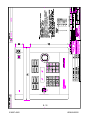
1
JPD100PLO
JOYSTICK
CONTROLLER
USER’S MANUAL
Ultrak®, Inc.
4465 Coonpath Road
Carroll, OH 43112
(800) 443-6680•(740) 756-9222•FAX (740) 756-4237
518007-4960
KEMU040020
April 25, 2001
WARNING
NOT FOR OUTDOOR USE.
TO REDUCE A RISK OF FIRE OR ELECTRIC SHOCK, DO
NOT EXPOSE THIS PRODUCT TO RAIN OR MOISTURE.
WARNING
THIS IS A CLASS A PRODUCT. IN A DOMESTIC
ENVIRONMENT, THIS PRODUCT MAY CAUSE RADIO
INTERFERENCE IN WHICH CASE THE USER MAY BE
REQUIRED TO TAKE ADEQUATE MEASURES.
NOTE
THIS EQUIPMENT HAS BEEN TESTED AND FOUND TO
COMPLY WITH THE LIMITS FOR A CLASS A DIGITAL
DEVICE, PURSUANT TO PART 15 OF THE FCC RULES.
THESE LIMITS ARE DESIGNED TO PROVIDE
REASONABLE PROTECTION AGAINST HARMFUL
INTERFERENCE WHEN THE EQUIPMENT IS OPERATED
IN A COMMERCIAL ENVIRONMENT. THIS EQUIPMENT
GENERATES, USES, AND CAN RADIATE RADIO
FREQUENCY ENERGY AND, IF NOT INSTALLED AND
USED IN ACCORDANCE WITH THE INSTRUCTION
MANUAL, MAY CAUSE HARMFUL INTERFERENCE TO
RADIO COMMUNICATIONS.
OPERATION OF THIS
EQUIPMENT IN A RESIDENTIAL AREA IS LIKELY TO
CAUSE HARMFUL INTERFERENCE IN WHICH CASE THE
USER WILL BE REQUIRED TO CORRECT THE
INTERFERENCE AT HIS OWN EXPENSE.
518007-4960
KEMU040020
April 25, 2001
Manual History
Issue 1 – April 25, 2001
©2001 BY ULTRAK®, INC.
ALL RIGHTS RESERVED
PRINTED IN THE UNITED STATES OF AMERICA
ULTRAK®, INCORPORATED
4465 COONPATH ROAD NW
CARROLL, OHIO 43112
(740) 756-9222
(800) 443-6681 TECHNICAL SUPPORT (TOLL FREE USA)
ALL RIGHTS RESERVED. NO PART OF THIS PUBLICATION MAY BE REPRODUCED BY ANY MEANS WITHOUT WRITTEN
PERMISSION FROM ULTRAK®, INCORPORATED.
THE INFORMATION IN THIS PUBLICATION IS BELIEVED TO BE ACCURATE IN ALL RESPECTS. HOWEVER, ULTRAK®,
INCORPORATED CANNOT ASSUME RESPONSIBILITY FOR ANY CONSEQUENCES RESULTING FROM THE USE
THEREOF. THE INFORMATION CONTAINED HEREIN IS SUBJECT TO CHANGE WITHOUT NOTICE. REVISIONS OR NEW
EDITIONS TO THIS PUBLICATION MAY BE ISSUED TO INCORPORATE SUCH CHANGES.
518007-4960
KEMU040020
April 25, 2001
DECLARATION OF CONFORMITY
To The European Community Council Directive 89/336/EEC
®
ISSUED BY:
Ultrak , Inc.
4465 Coonpath Road NW
Carroll, OH 43112
USA
Tel: (740) 756-9222
Fax: (740) 756-4237
MANUFACTURER:
DATE OF ISSUE:
TYPE OF EQUIPMENT:
Ultrak , Inc.
December 22, 1995
CCTV and Security Surveillance Equipment
MODEL NUMBER:
Alarm Interface Unit
AIU-100 - may be followed by any number of alphanumeric characters.
Auxiliary Interface Units
AIF-100/CO
Central Control Unit
CCU-100 - may be followed by any number of alphanumeric characters.
CCU-150 – may be followed by any number of alphanumeric characters.
CCU-200 – may be followed by any number of alphanumeric characters.
Joystick Multiplexer
MUX-100 – may be followed by any number of alphanumeric characters
MUX-05 – may be followed by any number of alphanumeric characters
Joystick Controller*
JPD-100, JPD-101, JPD-200 - may be followed by any number of
alphanumeric characters.
Small System Interface*
SSI-100 - may be followed by any number of alphanumeric characters.
Control Output Expander
COE-08, COE-16 - may be followed by any number of alphanumeric
characters
Control Receiver
CRX-610/BX, CRX-801AX, CRX-801BX
®
*Standard EN60065 does not apply.
STANDARDS TO WHICH
CONFORMITY IS DECLARED:
EN50081-1 Emissions Standard, and EN50082-1 Immunity Standard.
EN55022 Radiated, Class A, EN55022 Conducted, Class A, IEC-1000-42, ESD, IEC-1000-4-3, RF Fields, IEC-1000-4-4, Fast Transients/Burst.
EN60065 Safety Requirements for Mains Operated Electronic and
Related Apparatus for Household and Similar General Use
®
Ultrak , Inc. hereby declares that the models specified above conform to the directive and
standard as specified.
Donald L. Stephenson
Compliance Engineer
517775-3
518007-4960
Rev. O
August 25, 1999
KEMU040020
April 25, 2001
IMPORTANT SAFEGUARDS
1.
Read Instructions - All the safety and operating instructions should be read before the unit is
operated.
2.
Retain Instructions - The safety and operating instructions should be retained for future reference.
3.
Heed Warnings - All warnings on the unit and in the operating instructions should be adhered to.
4.
Follow Instructions - All operating and use instructions should be followed.
5.
Cleaning - Unplug the unit from the outlet before cleaning. Do not use liquid cleaners or aerosol
cleaners. Use a damp cloth for cleaning. See cleaning procedures under Maintenance.
6.
Water and Moisture - Do not use this unit near water or in an unprotected outdoor installation, or
any area which is classified as a wet location.
7.
Accessories - Do not place this unit on an unstable stand, tripod, bracket, or mount. The unit may
fall, causing serious injury to a person and serious damage to the unit. Use only with a stand,
tripod, bracket, or mount recommended by the manufacturer, or sold with the product. Any
mounting of the unit should follow the manufacturer’s instructions, and should use a mounting
accessory recommended by the manufacturer.
8.
Power Sources - This unit should be operated only from the type of power source indicated on the
marking label.
9.
Grounding or Polarization – The power supply supplied with this unit may be equipped with a
polarized alternating-current line plug (a plug having one blade wider than the other). This plug
will fit into the power outlet only one way. This is a safety feature. If you are unable to insert the
plug fully into the outlet, try reversing the plug. If the plug should still fail to fit, contact your
electrician to replace your obsolete outlet. Do not defeat the safety purpose of the polarized plug.
Alternately, this unit may be equipped with a 3-wire grounding-type plug, a plug having a third
(grounding) pin. This plug will only fit into a grounding-type power outlet. This is a safety feature.
If you are unable to insert the plug into the outlet, contact your electrician to replace your obsolete
outlet. Do not defeat the safety purpose of the grounding-type plug.
10.
Power-Cord Protection - Power supply cords should be routed so that they are not likely to be
walked on or pinched by items placed upon or against them, paying particular attention to cords
and plugs, convenience receptacles, and the point where they exit from the appliance.
11.
Overloading - Do not overload outlets and extension cords as this can result in a risk of fire or
electric shock.
12.
Object and Liquid Entry - Never push objects of any kind into this unit through openings as they
may touch dangerous voltage points or short-out parts that could result in a fire or electric shock.
Never spill liquid of any kind on the unit.
13.
Servicing - Do not attempt to service this unit yourself as opening or removing covers may expose
you to dangerous voltage or other hazards. Refer all servicing to qualified service personnel.
14.
Damage Requiring Service - Unplug the unit from the outlet and refer servicing to qualified service
personnel under the following conditions:
a.
b.
c.
518007-4960
When the power-supply cord or plug is damaged.
If liquid has been spilled, or objects have fallen into the unit.
If the unit has been exposed to rain or water.
KEMU040020
April 25, 2001
d.
e.
f.
If the unit does not operate normally by following the operating instructions. Adjust only
those controls that are covered by the operating instructions as an improper adjustment of
other controls may result in damage and will often require extensive work by a qualified
technician to restore the unit to its normal operation.
If the unit has been dropped or the enclosure has been damaged.
When the unit exhibits a distinct change in performance - this indicates a need for
service.
15.
Replacement Parts - When replacement parts are required, be sure the service technician has
used replacement parts specified by the manufacturer or have the same characteristics as the
original part. Unauthorized substitutions may result in fire, electric shock or other hazards.
16.
Safety Check - Upon completion of any service or repairs to this unit, ask the service technician to
perform safety checks to determine that the unit is in proper operating condition.
17.
Lightning - For added protection of this unit during a lightning storm, or when it is left unattended
and unused for long periods of time, unplug it from the wall outlet and disconnect the cable
system. This will prevent damage to the unit due to lightning and power-line surges.
518007-4960
KEMU040020
April 25, 2001
SAFETY PRECAUTIONS
CAUTION
RISK OF ELECTRIC
SHOCK, DO NOT OPEN
CAUTION: TO REDUCE THE RISK OF ELECTRICAL SHOCK, DO NOT OPEN
COVERS. NO USER SERVICEABLE PARTS INSIDE. REFER SERVICING TO
QUALIFIED SERVICE PERSONNEL.
This label may appear on the bottom of the unit due to space limitations.
The lightning flash with an arrowhead symbol, within an equilateral triangle, is intended to
alert the user to the presence of uninsulated “dangerous voltage” within the product’s
enclosure that may be of sufficient magnitude to constitute a risk of electric shock to
persons.
The exclamation point within an equilateral triangle is intended to alert the user to
presence of important operating and maintenance (servicing) instructions in the literature
accompanying the appliance.
220-240 Vac, 50 Hz power cords, input and output, must comply with the latest versions
of IEC Publication 227 or IEC Publication 245.
WARNING
TO PREVENT FIRE OR SHOCK HAZARD, DO NOT
EXPOSE THIS UNIT TO RAIN OR MOISTURE.
518007-4960
KEMU040020
April 25, 2001
HANDLING ELECTROSTATIC-SENSITIVE DEVICES
ATTENTION
OBSERVE PRECAUTIONS
FOR HANDLING
ELECTROSTATIC
SENSITIVE
DEVICES
WARNING
ELECTROSTATIC SENSITIVE DEVICE. USE PROPER
CMOS/MOSFET HANDLING PRECAUTIONS TO AVOID
ELECTROSTATIC DISCHARGE.
NOTE: Grounded wrist straps must be worn and proper
ESD safety precautions observed when handling the
electrostatic-sensitive printed circuit boards.
518007-4960
KEMU040020
April 25, 2001
SUPPLEMENTAL DATA
FOR
JPD-100PLO
The JPD100PLO Joystick Controller is a JPD100P controller with a special lockout
feature. The JPD100PLO requires firmware, part number 518007-4980.
The lockout feature allows an operator to enter a lockout code and leave the controller
inoperable until the code is entered again to unlock the controller. Use the following
procedure to lock and unlock the controller.
Press OPT
Press 2 (CNTL)
Press 3 (LOCKOUT)
The JPD100PLC display prompts you to enter a code. This code can be any 4-digit
code.
LOCKOUT FEATURE
ENTER CODE-
Enter the 4-digit code using the numeric keypad on the controller then press ENT.
518007-4960
S-1
KEMU040020
April 25, 2001
The JPD100PLC display prompts you to re-enter the code to verify it.
LOCKOUT FEATURE
RE-ENTER CODE-
Re-enter the same 4-digit code and press ENT. If you enter the same code, the
JPD100PLO displays the following message.
CONTROLLER LOCKED
ENTER CODE-
The controller is inoperable until an operator enters the 4-digit code that was entered to
lock the controller.
To unlock the controller, enter the 4-digit code entered to lock the controller and
press ENT. The message, “CONTROLLER UNLOCKED” flashes on the display and
the JPD100PLO returns to normal operation.
NOTE: If the JPD100PLO is powered down while in the locked mode, the unit will be in
the locked mode upon power-up.
RECOVERING FOR A LOST CODE
Perform the following procedure to recover from a lost code.
1)
Power down the JPD100PLO.
2)
Set the jumpers on the controller board for address 8. See paragraph 3.6 of this
manual for setting addresses.
3)
Power up the JPD100PLO.
518007-4960
S-2
KEMU040020
April 25, 2001
TABLE OF CONTENTS
Page
SECTION 1. INTRODUCTION ....................................................................................1-1
1.1
GENERAL ......................................................................................................1-1
1.2
DESCRIPTION...............................................................................................1-1
1.3
INSTALLATION/SET-UP ...............................................................................1-2
1.3.1
MUX-100 Multiplexer AND CCU-100B Central Control Unit ...................1-2
1.3.2
MSI-100 Medium System Interface Unit .................................................1-2
1.3.3
CCU-200 Communications Control Unit .................................................1-3
1.4
DEFINITIONS OF TERMS .............................................................................1-4
1.5
OPERATION ..................................................................................................1-6
1.6
SPECIFICATIONS .........................................................................................1-7
SECTION 2. OPERATION ..........................................................................................2-1
2.1
CONTROLS AND INDICATORS....................................................................2-1
2.1.1
Top Panel Controls and Indicators..........................................................2-1
2.1.2
Rear Panel Controls and Indicators ........................................................2-9
2.2
OPERATION ................................................................................................2-11
2.2.1
LCD Display Language Selection .........................................................2-13
2.2.2
Setting the Address in the KD6 Z-Series Dome....................................2-14
2.2.3
Primary Control Camera and Control Monitor. ......................................2-15
2.2.4
Secondary Control Camera And Monitor. .............................................2-21
2.2.5
Switch Secondary Control To Primary Control......................................2-25
2.2.6
Call Up Any Camera To Any Monitor. ...................................................2-26
2.2.7
PreShots ...............................................................................................2-28
2.2.7.1 Program PreShots .............................................................................2-28
2.2.7.2 List Programmed PreShots ...............................................................2-30
518007-4960
i
KEMU040020
April 25, 2001
TABLE OF CONTENTS
Page
2.7.2.3 Go To PreShot ..................................................................................2-31
2.2.8
VectorScans..........................................................................................2-33
2.2.8.1 Programming VectorScans in the KD6 Z-Series Dome.....................2-33
2.2.8.2 List VectorScans ...............................................................................2-34
2.2.8.3 List VectorScan Contents ..................................................................2-35
2.2.8.4 Run VectorScan ................................................................................2-36
2.2.8.5 Stop VectorScan ...............................................................................2-38
2.2.9
Sector ID's.............................................................................................2-39
2.2.10
Freeze/Unfreeze Video & Flashback Function (KD6 UltraDome only)..2-40
2.2.11
Tours (KD6 UltraDome only).................................................................2-41
2.2.11.1 Programming Tours...........................................................................2-41
2.2.11.2 Run Tour ...........................................................................................2-42
2.2.11.3 Stop Tour...........................................................................................2-43
2.2.12
MultiCall Control (00-255). ....................................................................2-44
2.2.13
Auxiliary Contact Output Control (ON/OFF). .........................................2-50
2.2.14
Alarm Control (Enable/Disable/Acknowledge) ......................................2-53
2.2.15
Manual Control of SmartScan. ..............................................................2-56
2.2.16
Find Home. ...........................................................................................2-57
2.2.17
Joystick Diagnostics..............................................................................2-58
2.2.18
Camera ID Display on Monitor. .............................................................2-60
2.2.19
Pan, Tilt Azimuth Display/Error Log Display..........................................2-62
SECTION 3. INSTALLATION AND INTERCONNECTIONS.......................................3-1
3.1
GENERAL ......................................................................................................3-1
3.2
HANDLING PROCEDURES ..........................................................................3-1
3.3
INTERCONNECTING CABLING REQUIREMENTS......................................3-2
518007-4960
ii
KEMU040020
April 25, 2001
TABLE OF CONTENTS
Page
3.3.1
8-Pin Telephone Jack Connector............................................................3-2
3.3.2
5-Pin DIN Keyboard Connector...............................................................3-2
3.4
CONNECTOR PIN-OUT ASSIGNMENTS .....................................................3-3
3.5
JDP-100/P EQUIPMENT INTERCONNECTIONS .........................................3-3
3.5.1
MUX-100 Multiplexer...............................................................................3-4
3.5.2
MSI-100 Medium System Interface Unit .................................................3-4
3.5.3
CCU-200 Communications Control Unit .................................................3-4
3.5.4
Daisy-Chain Wiring DIA-01 Control Interface Adapters ..........................3-5
3.6
JPD-100/P ADDRESSING ...........................................................................3-11
3.7
INSTALLATION DRAWINGS.......................................................................3-13
SECTION 4. MAINTENANCE .....................................................................................4-1
4.1
GENERAL ......................................................................................................4-1
4.2
MAINTENANCE PROCEDURES...................................................................4-1
4.3
RETURNING EQUIPMENT TO ULTRAK ......................................................4-4
APPENDIX A. REFERENCE MATERIALS ................................................................ A-1
A.1
USER'S MANUAL INDEX ................................................................................. 1
APPENDIX B. QUICK REFERENCE GUIDE................................................................. 1
INDEX ............................................................................................................................. 1
518007-4960
iii
KEMU040020
April 25, 2001
LIST OF FIGURES
Page
Figure 2-1. CONTROLS AND INDICATORS, TOP PANEL ........................................2-1
Figure 2-2. CONTROLS AND INDICATORS, REAR PANEL ......................................2-9
Figure 3-1. JPD-100/P CONNECTIONS TO MUX-100 MULTIPLEXER .....................3-6
Figure 3-2. JPD-100/P CONNECTIONS TO MSI-100 MEDIUM SYSTEM
INTERFACE UNIT .....................................................................................3-7
Figure 3-3. JPD-100/P CONNECTIONS TO CCU-200 COMMUNICATION
CONTROL UNIT (REAR PANEL)..............................................................3-8
Figure 3-3. TERMINATING THE DIA-01 CONTROL INTERFACE ADAPTER .........3-11
Figure 3-4. JUMPER SETTINGS ..............................................................................3-12
LIST OF DRAWINGS
Page
JPD-100/P Smart Hand Controller Unit Installation (D/N 517057-5430) ....................3-10
DIA-01 Control Interface Adapter Installation (D/N 515558-2430) .............................3-11
DIA-01/X Control Interface Adapter Installation (D/N 515558-4430) ..........................3-12
LIST OF TABLES
Page
Table 2-1. CONTROL COMMANDS .........................................................................2-64
Table 3-1. JPD-100/P ADDRESSING .......................................................................3-12
518007-4960
iv
KEMU040020
April 25, 2001
SECTION 1. INTRODUCTION
1.1
GENERAL
The JPD-100/P Controller is used to control FastScan/SmartScan receiver units,
a CCU-100/B Central Control Unit, CCU-200 Communications Control Unit and
CAT Video Switcher or an MSI-100 Medium System Interface Unit. The JPD100/P Controller is designed to control the many different features of all the
Diamond pan and tilt units available. The JPD-100/P Controller may have a
feature that is not supported by your model pan and tilt unit. Refer to your
specific pan and tilt unit’s operation and programming manual for the available
features.
The JPD-100/P Controller is designed for use in systems requiring four to thirtytwo control locations. There are three system configurations for the JPD-100/P
Controllers.
1)
2)
3)
1.2
MUX-100 Multiplexer (up to eight JPD-100/P Controllers), CCU-100/B
Central Control Unit and FastScan/SmartScan units with firmware
supporting the 19.2K baud rate for proper system operation.
MSI-100 Medium System Interface (up to four JPD-100/P Controllers) and
standard FastScan/SmartScan units.
CCU-200 Communications Control Unit (up to 8 JPD-100/P Controllers can
be connected to one channel of the CCU-200; maximum of 4 channels for
a total of 32 controllers)
DESCRIPTION
Each JPD-100/P consists of one 3-axis proportional joystick for pan, tilt, and
zoom control, one 2-axis joystick for iris and focus control, two 12-key keypads
for data entry and system control, eight programmable function keys, an LCD
display, and a KBD-100A keyboard (AT-style) interface. The language for the
LCD display is selectable between English, Spanish, German, and French.
518007-4960
1-1
KEMU040020
April 25, 2001
1.3
1.3.1
INSTALLATION/SET-UP
MUX-100 Multiplexer AND CCU-100B Central Control Unit
Each JPD-100/P Controller must be connected to a DIA-01 Control Interface
Adapter. The DIA-01 provides the +5Vdc power required to power the JPD100/P circuitry. The DIA-01 also provides the communications interface
between the MUX-100 Multiplexer and the JPD-100/P Controllers. Up to
eight JPD-100/P Controllers can be connected to the MUX-100 Multiplexer
by daisy-chain wiring the DIA-01 Control Interface Adapters.
Each JPD-100/P must have a unique address (1-8). The address is set
using jumpers on the circuit board inside the unit. Refer to Section 3,
paragraph 3.6 for the jumper settings.
A KBD-100A Keyboard can be connected to the JPD-100/P Controller for
programming and storing PreShots, VectorScans, and Sector ID's in
SmartScan Units. However, the KBD-100 keyboard is usually connected to
the CCU-100/B Central Control Unit. With this setup, the CCU-100/B and
the SmartScan Units can be programmed without moving the keyboard.
1.3.2
MSI-100 Medium System Interface Unit
One of the JPD-100/P Controllers can be connected to the front panel
controller connector on the MSI-100. Three other JPD-100/P Controllers can
be connected to DIA-01 Control Interface Adapters. The DIA-01 provides
+5Vdc to power the JPD-100/P circuitry. The DIA-01 also provides the
communications interface between the MSI-100 and the JPD-100/P
Controllers. Up to three JPD-100/P Controllers can be connected to the rear
518007-4960
1-2
KEMU040020
April 25, 2001
panel of the MSI-100 by daisy-chain wiring the DIA-01 Control Interface
Adapters.
Each JPD-100/P must have a unique address (1-4). The address is set
using jumpers on the circuit board inside the unit. Refer to Section 3,
paragraph 3.6 for the jumper settings.
The KBD-100 Keyboard is connected to any of the JPD-100/P Controllers in
the system for programming and storing PreShots, VectorScans, and Sector
ID's in SmartScan Units and programming the MSI-100 Medium System
Interface Unit.
1.3.3
CCU-200 Communications Control Unit
One JPD-200/P Controller can be plugged directly into the front panel of the
CCU-200 using the coiled cable supplied with the controller. Up to thirty-one
(31) additional JPD-200/P Controllers can be connected to DIA-01 Control
Interface Adapters, then connected to the rear panel of the CCU-200. Up to
eight Control Interface Adapters can be daisy-chain wired and connected to
one RS-485 port on the CCU-200 rear panel. Each JPD-100P connected to
the rear panel requires a DIA-01 control interface adapter. The DIA-01
provides +5Vdc to power the JPD-100/P circuitry. The DIA-01 also provides
the communications interface between the CCU-200 and the JPD-100/P
Controllers. Up to 32 JPD-100/P Controllers can be connected to the CCU200.
Each JPD-100/P must have a unique address (1-8). The address is set
using jumpers on the circuit board inside the unit. Refer to Section 3,
paragraph 3.6 for the jumper settings.
518007-4960
1-3
KEMU040020
April 25, 2001
The KBD-100A Keyboard is connected to any of the JPD-100/P Controllers
in the system for programming and storing PreShots, VectorScans, and
Sector ID's in SmartScan Units. A JPD-100P must be connected to the front
panel on the CCU-200 to program the CCU-200 Communications Control
Unit.
1.4
DEFINITIONS OF TERMS
The following terms are used throughout this manual. Please become familiar
with them before programming the SmartScan units, CCU-100/B Central Control
Unit or MSI-100 Medium System Interface Unit. Refer to the specific Operation
and Programming Manual for programming procedures for the SmartScan units,
the CCU-100/B Central Control Unit, and MSI-100 Medium System Interface
Unit.
PreShot
A standard PreShot is a camera/lens position including pan, tilt, zoom, and focus
that can be given a 16-character title and stored in a SmartScan, SmartScan
Pro, or SmartScan Pro II, or given a 24-character title and stored in a SmartScan
III Unit. Up to 100 (00-99) PreShots can be programmed and stored in each
SmartScan unit. Standard PreShots can be programmed using a KBD-100
Programming Keyboard and the JPD-100/P Controller.
A “Quick” PreShot is a camera/lens position including pan, tilt, zoom, and focus
that is stored in the scan, but the PreShot name is not programmable. The
controller assigns the PreShot title. The title of the PreShot is the number of the
PreShot; for example, the title for “Quick” PreShot 5, PreShot 05. “Quick”
PreShots can be programmed using only the JPD-100/P Controller.
518007-4960
1-4
KEMU040020
April 25, 2001
An operator can send a SmartScan unit to a programmed PreShot using the
JPD-100/P Controller or the KBD-100 Keyboard. When the SmartScan unit is
viewing the PreShot, the title of the PreShot is added to the video signal.
VectorScan
A VectorScan can be considered a video tour. It is two or more PreShots (up to
64) from the same scan unit linked together with specified dwell times. Up to ten
(0-9) VectorScans can be stored in each SmartScan, SmartScan Pro,
SmartScan Pro II, and SmartScan III unit. The VectorScan title can be up to 16
characters in the SmartScan, SmartScan Pro, and SmartScan Pro II units and up
to 24 characters in SmartScan III units. VectorScans are programmed using the
KBD-100 Keyboard and the JPD-100/P Controller. They can be started/stopped
using the JPD-100/P Controller or KBD-100 Keyboard. When a VectorScan is
running in a SmartScan unit, the title of the PreShot currently being viewed is
added to the SmartScan video signal.
Sector ID
Sector ID's are used for labeling specific areas that the scan unit views. Up to
16 Sector IDs can be programmed and stored in each SmartScan unit. The
Sector ID title can be up to 16 characters in SmartScan, SmartScan Pro, and
SmartScan Pro II units, and up to 24 characters in SmartScan III units. Sector
ID's are programmed using a KBD-100 Programming Keyboard and the JPD100/P Controller. Whenever the dome is under manual control and viewing a
programmed sector, the title of the sector is added to the SmartScan video
signal.
MultiCall
A MultiCall can be programmed to perform one or more system functions at the
same time or in series with programmable dwell times between each function.
The system functions that can be included in a MultiCall are PreShots,
VectorScans, video switching, turning on/off VCR's or other auxiliary devices, or
starting a MultiCall (including itself). MultiCalls are used to define the system's
response to events such as date/time, alarms and JPD-100/P Controller function
518007-4960
1-5
KEMU040020
April 25, 2001
keys. A MultiCall can also be used to sequence cameras on a monitor. Up to
256 (00-255) MultiCalls can be programmed and stored with a 16-character title
in the CCU-100/B Central Control Unit. Up to 251 (0-250) MultiCalls can be
programmed and stored with a 16-character title in the MSI-100 Medium System
Interface Unit.
1.5
OPERATION
The JPD-100/P Controller is polled by the MSI-100, CCU-200, or MUX-100 for
key commands. An operator at each JPD-100/P Controller can perform the
following system functions:
• Manual control (pan, tilt, zoom, focus, and iris) of FastScan or SmartScan
•
•
•
•
•
•
•
•
•
•
domes. Lens iris manual control requires MIO-100 auto iris override option in
standard FastScan or SmartScan. The FastScan Pro II, SmartScan Pro II,
SmartScan III Series, UltraDome KD6, and KD6 Z-Series Dome units provide
auto/manual iris as a standard feature.
Video switching: 250 cameras to 32 monitors
Program “Quick” PreShots in SmartScan domes
Execute PreShots
Program VectorScans (1-3) in the KD6 Z-Series Dome
Start/stop VectorScans
List programmed PreShots, VectorScans, VectorScan contents, and Sector
IDs stored in SmartScan units (not available in KD6 Z-Series Dome)
Control auxiliary devices
Set the address of the KD6 Z-Series Dome
Program Tours and Run Tours in the KD6 UltraDome
Freeze and unfreeze the video scene in the KD6 UltraDome
These controllers allow the operators to have a primary control camera and
monitor (1st line of display) and a secondary control camera and monitor (2nd line
of display). If a secondary camera/monitor is not selected, all control and
programming procedures are sent to the primary camera. If a secondary
518007-4960
1-6
KEMU040020
April 25, 2001
camera/monitor is selected, all manual control (pan, tilt, zoom, focus, and iris),
auxiliary control, and programming procedures are sent to the primary control
camera and viewed on the primary control monitor. All automatic control
(PreShots, VectorScans) is sent to the secondary control camera. If the
secondary control camera is switched to the secondary control monitor, the video
from the secondary camera is viewed on the secondary control monitor.
Each JPD-100/P can be used to enable, disable, or acknowledge alarms. Up to
255 alarms are available with AIU-100 Alarm Interface Units connected to the
CCU-100/B. Up to 32 alarms are available with the MSI-100 Medium System
Interface Unit. Individual alarms or all alarms can be enabled or disabled. The
oldest alarm or all alarms can be acknowledged.
Each JPD-100/P has eight programmable function (quick) keys. The function
keys are programmed by programming the desired MultiCall for each key, then
assigning the MultiCalls to the function keys. The function keys are designed to
perform a single system action or many system actions using a single key stroke.
The actions can be initiated simultaneously or in a series with dwell times (up to
99 seconds) between each action. The actions that can be programmed for a
function key are PreShots, VectorScans, Video Switching, and Auxiliary Control
(VCR's), and MultiCalls. Pressing the function key once starts the assigned
MultiCall. Pressing the function key again stops the assigned MultiCall.
1.6
SPECIFICATIONS
Power Requirements:
Voltage Requirements:
Communication:
Baud Rate:
Operating Temperature:
Humidity:
518007-4960
300ma Max.
+5Vdc ±5%
RS-422 Twisted-Pair
19.2K Baud
+32°F (0°C) to 120°F (+50°C)
0 to 95% relative, non-condensing
1-7
KEMU040020
April 25, 2001
This page left blank intentionally.
518007-4960
1-8
KEMU040020
April 25, 2001
SECTION 2. OPERATION
2.1
2.1.1
CONTROLS AND INDICATORS
Top Panel Controls and Indicators
Figure 2-1. CONTROLS AND INDICATORS, TOP PANEL
518007-4960
2-1
KEMU040020
April 25, 2001
LARGE JOYSTICK OPERATION
1
LARGE JOYSTICK
The joystick control is rate proportional; the farther the joystick is moved, the
faster the function is performed.
The large joystick is also used to halt VectorScans in a SmartScan unit and return
the SmartScan to manual control. The SmartScan unit where the VectorScan is
running must be the primary control camera. Move the joystick in any direction
while a VectorScan is running to stop the VectorScan.
Auto Pivot Function
If the auto pivot function is enabled in the SmartScan unit, the pan and tilt rotates
180° when the camera reaches vertical. This function assists operators in tracking
an individual that moves directly under the camera. When the camera is in the
vertical position, push the large joystick down and hold it down until the pan and tilt
rotates 180°; continue holding the joystick down and the unit tilts up as long as the
joystick remains in the “down” position. When the joystick is returned to its neutral
position, operation returns to normal. Refer to your specific pan and tilt unit’s
user’s manual for availability of this feature.
518007-4960
2-2
KEMU040020
April 25, 2001
SMALL JOYSTICK OPERATION
PASS Function
If the PASS function is enabled in the SmartScan unit, the pan and tilt speed
range is a function of the lens zoom angle. As the lens is zoomed in, the
maximum pan and tilt speeds are reduced and the low speed control is expanded.
Refer to your specific pan and tilt unit’s user’s manual for availability of this
feature.
2
SMALL JOYSTICK
The focus functions are operational upon power-up of the unit. The iris function
is set to automatic upon power-up of the unit. To manually control the iris, the
MIO-100 Option must be installed on the FastScan or SmartScan unit and
manual iris must be selected on the JPD-100/P Controller.
518007-4960
2-3
KEMU040020
April 25, 2001
SMALL JOYSTICK OPERATION
MANUAL IRIS CONTROL
STEP 1
Press the IRIS key on the function keypad and then the 2 key on the numeric
keypad.
When manual iris is selected for the control camera, the letter I appears on
the second line of the LCD display.
CNTL - CAM 1
I
MON 1
NOTE
When the operator changes the control
camera, the iris function stays in manual.
518007-4960
2-4
KEMU040020
April 25, 2001
SMALL JOYSTICK OPERATION
AUTOMATIC IRIS
The operator can change back to automatic iris anytime while controlling
the camera.
STEP 1
Press the IRIS key on the function keypad and then the 1 key on the
numeric keypad.
When automatic iris is selected, the letter I disappears from the second
line of the LCD display.
CNTL - CAM 1 MON 1
518007-4960
2-5
KEMU040020
April 25, 2001
LCD DISPLAY
NUMERIC KEYPAD
3
LCD DISPLAY
The display is a 2X20 EL back light super twist LCD. The viewing angle of the
display may be changed by turning the screwdriver adjustment on the back panel
(see figure 2-2). The first line of the display indicates the primary monitor
(number) and camera (number) the hand controller unit is controlling. The
second line indicates the secondary camera (number) and monitor (number), if
one is selected. The language (English, Spanish, German, or French) for the
LCD display is selectable.
The second line of the display shows each keystroke as it is entered. Any input
errors may be corrected by pressing the CLEAR key and re-entering the data.
All messages and prompts are also displayed on the second line. The display
blinks at various data entry points to indicate more data needs to be entered or a
key pressed to complete a command. The JPD-100/P returns to the secondary
camera/monitor when done displaying messages or prompts.
4
NUMERIC KEYPAD
The numeric keypad is used to enter camera numbers, monitor numbers,
PreShot numbers, VectorScan numbers, alarm numbers, etc. The CLEAR key is
used to clear data entries or the second camera and monitor. The ENTER key is
used to complete a data or function entry.
518007-4960
2-6
KEMU040020
April 25, 2001
FUNCTION KEYPAD
5
FUNCTION KEYPAD
The function keypad is used in conjunction with the numeric keypad to carry out
the control functions of the FastScan/SmartScan assemblies, CATS Video
Switcher, CCU-100/B Central Control Unit or MSI-100 Medium System Interface,
and auxiliary devices.
- Camera/Monitor Switching (up to 250 cameras to 32 monitors) - CAM, MON,
ENTER, CNTL
- Manual/Auto Iris Control (if option is installed in FastScan/SmartScan receiver
unit) - IRIS
- Auxiliary Output Control: ON/OFF (if used with CATS® video switcher, AIF100/CO, CRX-800 Series Control Receivers, CRX-500 Control Receivers) - AUX
- Alarm Control: Enable/Disable/Acknowledge Alarms (MSI-100 Medium System
Interface, or if AIU-100 Alarm Interface Units or AIF-100 Auxiliary Alarm Interface
units are connected to a CCU-100/B) - ALARM
- Program “Quick” PreShot – PRGM
- PreShot Call-up - PSHOT
- PreShot Listing - OPT
- Program VectorScans 1-3 in the KD6 Z-Series Dome (OPT)
- Run VectorScan - VSCAN
- VectorScan Listing - OPT
- Sector Listing - OPT
- Control (Start/Stop/Hold) MultiCalls - MCALL
- JPD-100/P Diagnostics - OPT
- SmartScan Functions (find home, manual control) - OPT
- Enable/Disable Camera ID Display, Coordinate Display or Error Log Display –
OPT
- Select LCD Display Language (OPT)
- Set address in KD6 Z-Series Dome (OPT)
- Program and Run Tours in KD6 UltraDome (OPT)
- Freeze and Unfreeze video in the KD6 UltraDome (OPT)
- Flashback Function in the KD6 UltraDome (OPT)
The SEQ key is not functional on the JPD-100/P Controllers. Monitor
sequencing must be done using the MultiCall function in the CCU-100/B Central
Control Unit, MSI-100 Medium System Interface Unit, or CCU-200
Communications Control Unit. Refer to the CCU-100/B, MSI-100, or CCU-200
User's Manual for programming procedures.
518007-4960
2-7
KEMU040020
April 25, 2001
FUNCTION KEYS 1 THROUGH 8
6
FUNCTION KEYS
Function Keys 1 through 8
Function keys 1 through 8 are programmed by programming a MultiCall, then
assigning the MultiCall to the function key. The function keys are designed to
perform a single system action or many system actions using a single key stroke.
The actions can be initiated simultaneously or in a series with dwell times (up to
99 seconds) between each action. The actions that can be programmed for a
function key are PreShots, VectorScans, video switching, auxiliary control (video
recording), and MultiCalls. Pressing the function key once starts the assigned
MultiCall. Pressing the function key again stops the assigned MultiCall. If the
key is not programmed, nothing happens when the key is pressed. Refer to the
CCU-100/B or MSI-100 User’s Manual for programming MultiCalls and assigning
MultiCalls to function keys.
NOTE
If a VectorScan is started when a function key
is pressed, the VectorScan continues to run
until manual control of the camera is taken.
Pressing the function key again does not halt a
VectorScan.
Function keys 5, 6, and 7 can also be set to run tours 1,2, and 3, respectively.
Function key 4 can be set to invoke the flashback function in the KD6. Function
key 8 can be set to enable and disable the freeze frame feature in the KD6
UltraDome. Refer to paragraphs 2.2.10 and 2.2.11.
518007-4960
2-8
KEMU040020
April 25, 2001
VIEWING ANGLE ADJUSTMENT
TELEPHONE JACK CONNECTOR
2.1.2
Rear Panel Controls and Indicators
Figure 2-2. Controls and Indicators, Rear Panel
7
VIEWING ANGLE ADJUSTMENT
This screwdriver adjustment is used to change the viewing angle of the LCD
Display.
8
8-PIN TELEPHONE JACK CONNECTOR
This connector inputs power for the JPD-100/P Joystick Controller and outputs
RS-422 control data. A coiled cable assembly (P/N 849518-0306) is provided
with the unit for connection to the various equipment types.
518007-4960
2-9
KEMU040020
April 25, 2001
KEYBOARD CONNECTOR
9
5-PIN DIN CONNECTOR
This connector is used for connection to the KBD-100 keyboard interface. The
KBD-100 Keyboard is used to program PreShots, VectorScans, and Sector ID's
in SmartScan units.
NOTE
In a system with a CCU-100B, the KBD-100
keyboard should be plugged into the front
panel connector on the CCU-100/B Central
Control Unit.
From the CCU-100/B, the
keyboard can be used to program both the
CCU-100/B and the SmartScan units. The
CCU-100/B functions, such as MultiCalls,
cannot be programmed when the KBD-100 is
plugged into the keyboard connector on the
JPD-100/P.
518007-4960
2-10
KEMU040020
April 25, 2001
2.2
OPERATION
CAUTION
Before Powering-Up The System, Make
Sure
The
Programming
Keyboard
Is
Plugged Into The JPD-100/P Controller or
the CCU-100/B Central Control Unit (if
applicable). If The Keyboard Is Plugged In
After Power-Up, Improper Operation May
Occur.
Operation can begin when power is applied to all components in the system.
Upon power-up, the following screens are displayed.
Diamond Electronics
JPD-100/P
3 seconds
Diamond Electronics
518007-2980 Rev D
3 seconds
Diamond Electronics
JPD. Address = #
3 seconds
CNTL – CAM - 1 MON – 1
OPT>1 >1 to Change Lang
3 seconds
To change the language, see paragraph 2.2.1.
CNTL – CAM - 1 MON – 1
518007-4960
2-11
KEMU040020
April 25, 2001
Camera one is the control camera and monitor one is the control monitor. All
operator control data (pan, tilt, zoom, focus, iris, PreShots, VectorScans, etc.) is
sent to camera one. To control another camera, see paragraph 2.2.2.
A secondary control camera/monitor has to be selected by an operator. A video
switcher is usually installed in a system with more than one camera and/or
monitor. If a secondary control camera is selected, all manual control data (pan,
tilt, zoom, focus, and iris), camera power control and auxiliary control are sent to
the primary control camera and all automatic control data (PreShot, VectorScan)
is sent to the secondary control camera.
NOTE
If power is interrupted to the system,
unplug the JPD-100/P Controller for 5
seconds and then plug it back in. If this
procedure is not done, incorrect operation
may occur.
518007-4960
2-12
KEMU040020
April 25, 2001
2.2.1
LCD Display Language Selection
Upon power-up of the controller, the second line of the LCD display shows:
CNTL – CAM 1
MON 1
OPT>1 >1 to Change Lang
The language for the LCD display is selectable between English, French,
German, and Spanish.
To select the language used for the LCD display,
Press OPT to view the LCD menu options
OPT
Press 1 (MISC)
1
Press 1 (LANG)
1
Press 1 for English,
1
Press 2 for Spanish,
2
Press 3 for German, or
3
Press 4 for French.
4
The LCD menus, messages, and prompts are displayed in the language
selected.
518007-4960
2-13
KEMU040020
April 25, 2001
SET ADDRESS IN KD6 Z-SERIES DOME
2.2.2
Setting the Address in the KD6 Z-Series Dome
To set the address of a KD6 Z-Series Dome, you must know the serial
number. The serial number is eight (8) digits and can be located on the KD6
Z-Series Dome pan and tilt unit. Note: all other dome addresses are set
using rotary switches or a DIP switch on the receiver board.
Press OPT to view the LCD menu options
OPT
Press 1 (MISC)
1
Press 2 (SET ADD) to set the address
2
Enter the Serial Number (8 digits)
of the KD6 Z-Series Dome (SN-). Enter the leading
character A of the serial number as a 0.
SN#
Press Enter.
Enter
Enter the desired address of the dome (1-250)
Press Enter
###
Enter
The LCD displays the message, “Updating Address”.
The address is the camera number the operator uses to call-up and control
the dome.
518007-4960
2-14
KEMU040020
April 25, 2001
PRIMARY CONTROL CAMERA
2.2.3
Primary Control Camera and Control Monitor.
Upon power-up of the system, the primary control camera and monitor are
camera one and monitor one.
A secondary control camera/monitor
combination, if desired, has to be selected.
The first line of the display on the JPD-100/P shows the CAM and the MON
the JPD-100/P is controlling. On the JPD-100/P controller, the camera
number has a symbol that looks like a camera beside it and the monitor
number has a symbol that looks like a monitor beside it.
CNTL - CAM 1
MON 1
Use the following command sequences to change the primary camera/monitor combination currently under control of the JPD-100/P Joystick
Controller.
CHANGE PRIMARY CONTROL CAMERA
To change the control camera (but not the control monitor), enter the
following command sequence.
NOTE
The commands are in bold typeface and are
separated by the symbol >.
518007-4960
2-15
KEMU040020
April 25, 2001
PRIMARY CONTROL CAMERA
Camera #>ENTER
or
Camera#>CNTL
#
ENTER
#
CNTL
The JPD-100/P sends a command to the switcher to switch the
selected camera to the monitor currently displayed on the JPD-100/P
Controller.
NOTE
If the CCU-100/B or MSI-100 has been
programmed (camera controller partitioning) to
deny the controller access to a camera; when
the operator selects that camera, the message
"Request Denied" appears on the second line
of the JPD-100/P display.
CNTL - CAM 1
Request Denied
MON 1
NOTE
If a camera number is displayed on the first
line of the JPD display, but the operator cannot
manually control that camera, press the CNTL
key to get manual control (if the controller has
access capability).
The controller loses
manual control when more than one JPD100/P is addressed to the same camera or
when a MultiCall calls the camera addressed
by the JPD-100/P.
518007-4960
2-16
KEMU040020
April 25, 2001
PRIMARY CONTROL CAMERA
Example:
The display on the JPD-100/P controller shows CAM 1 and MON 1.
CNTL - CAM 1
MON 1
Enter the following command sequence to change the control camera
to 5.
5>ENTER
or
5>CNTL
Now, the JPD-100/P display shows CAM 5/MON1.
CNTL - CAM 5
MON 1
All control commands are performed on camera 5 and the video from
camera 5 is viewed on monitor 1.
518007-4960
2-17
KEMU040020
April 25, 2001
PRIMARY CONTROL MONITOR
CHANGE PRIMARY CONTROL MONITOR
There are two different ways to select a control monitor.
1.
The following command sequences change the control monitor
and leave the primary control camera displayed on the first line of
the JPD-100. The video from the primary control camera is
switched to the new monitor.
To change the control monitor (but not the control camera), enter
one of the following command sequences.
a.
Monitor #>MON>ENTER
#
MON
ENTER
NOTE
If the MSI-100 has been programmed (monitor
controller partitioning) to deny the controller
access to a monitor; when the operator selects
that monitor, the message "Request Denied"
appears on the second line of the JPD-100/P
display.
Example:
The display on the JPD-100/P shows CAM 1/MON 1.
CNTL - CAM 1
518007-4960
MON 1
2-18
KEMU040020
April 25, 2001
PRIMARY CONTROL MONITOR
Enter the following command sequence to change the control
monitor to 3.
3>MON>ENTER
Now the JPD-100/P display shows CAM 1/MON 3.
CNTL - CAM 1
MON 3
All control commands are performed on camera 1 and the video
from camera 1 is viewed on monitor 3.
2.
The following command sequences change the primary control
monitor and also changes the primary control camera on the JPD100/P Controller to the camera currently displayed on the monitor.
No video switching occurs, only control changes.
a.
Monitor #>MON>CNTL
#
MON
CNTL
Example:
The display on the JPD-100/P shows CAM 1/MON 1.
CNTL - CAM 1
MON 1
Enter the following command sequence to change the
control monitor to 3 and change the control camera to the
camera presently displayed on monitor 3. For the example,
camera 2 is currently displayed on (switched to) monitor 3.
518007-4960
3>MON>CNTL
2-19
KEMU040020
April 25, 2001
PRIMARY CONTROL MONITOR
Now the JPD-100/P display shows CAM 2/MON 3.
CNTL - CAM 2
MON 3
All control commands are performed on camera 2 and the
video from camera 2 is viewed on monitor 3.
518007-4960
2-20
KEMU040020
April 25, 2001
SECONDARY CONTROL CAMERA
2.2.4
Secondary Control Camera And Monitor.
The secondary camera and monitor are displayed on the second line of the
display. The camera number can be entered first and the monitor number
second or vice versa.
If the monitor number is entered first, it appears on the second line. When
the camera number is entered, the JPD-100/P places the camera number in
front of the monitor number.
NOTE
If the CCU-100/B or MSI-100 has been
programmed (camera controller partitioning) to
deny the controller access to a camera; when
the operator selects that camera, the message
"Request Denied" appears on the second line
of the JPD-100/P display.
If the MSI-100 has been programmed (monitor
controller partitioning) to deny the controller
access to a monitor; when the operator selects
that monitor, the message "Request Denied"
appears on the second line of the JPD-100/P
display.
SELECT A SECONDARY CAMERA
518007-4960
2-21
KEMU040020
April 25, 2001
SECONDARY CONTROL CAMERA
To select a secondary camera, enter the following command sequence.
Camera #>CAM
#
CAM
The camera number selected appears on the second line of the
controller's LCD display.
All automatic commands (PreShot,
VectorScan) are sent to the secondary camera.
Example:
Select camera 2 as the secondary camera.
2>CAM
The number 2 shows up on the second line of the JPD-100/P display.
CNTL - CAM 1 MON 1
2
All automatic commands (PreShots, VectorScans) are sent to camera
2.
518007-4960
2-22
KEMU040020
April 25, 2001
SECONDARY CONTROL MONITOR
SELECT A SECONDARY MONITOR
To select a secondary monitor, enter the following command sequence.
Monitor #>MON
#
MON
The secondary monitor appears on the second line of the JPD-100/P
display.
Example:
Select monitor 2 as the secondary monitor.
2>MON
Monitor 2 appears on the second line of the JPD-100/P display.
CNTL - CAM 1 MON 1
22
518007-4960
2-23
KEMU040020
April 25, 2001
SECONDARY CAMERA/MONITOR
CALL UP SECONDARY CAMERA TO SECONDARY MONITOR
To switch the video of the secondary camera to the secondary monitor, the
secondary camera and monitor must be selected first and displayed on the
second line of the JPD-100/P LCD display. Press the ENTER key on the
JPD-100/P. The JPD-100/P sends out a command to the switcher to switch
the secondary camera to the secondary monitor.
The following message is briefly displayed after pressing ENTER.
CNTL - CAM 1
Call CAM# MON#
MON 1
CLEAR SECONDARY CAMERA/MONITOR
Press the CLEAR key on the numeric keypad until the second line is clear.
518007-4960
2-24
KEMU040020
April 25, 2001
SECONDARY CONTROL TO PRIMARY CONTROL
2.2.5
Switch Secondary Control To Primary Control.
To have the secondary camera/monitor combination displayed become the
primary camera/monitor combination, press CNTL. The camera/monitor
combination on the second line of the LCD display moves to the first line of
the display. The second line of the display is empty.
Example:
CAM 1/MON 1 is the primary control camera/monitor combination and CAM
2/MON 2 is the secondary camera/monitor combination.
CNTL - CAM 1
2 2
MON 1
Press CNTL.
CAM 2 and MON 2 become the primary control camera/monitor combination and the second line disappears.
CNTL - CAM 2
518007-4960
MON 2
2-25
KEMU040020
April 25, 2001
VIDEO SWITCHING
2.2.6
Call Up Any Camera To Any Monitor.
To call up any camera to any monitor without giving up PreShot and
VectorScan control of the primary camera, perform the procedures for calling
up a secondary camera to a secondary monitor. Then clear them from the
display on the JPD-100/P by pressing the CLEAR key until the second line of
the display is empty. The video from the secondary camera remains on the
secondary monitor until the switcher receives a switching command involving
either the camera or monitor.
#
CAM
#
MON
ENTER
CLEAR
CLEAR
Example:
Call up Camera 2 to Monitor 2.
Present LCD Display:
CNTL - CAM 1
MON 1
2>CAM
CNTL - CAM 1
2
518007-4960
MON 1
2-26
KEMU040020
April 25, 2001
VIDEO SWITCHING
2>MON
CNTL - CAM 1
2 2
MON 1
ENTER
The JPD-100/P sends out a command to switch camera 2 to monitor 2.
CLEAR
CNTL - CAM 1
2
MON 1
CLEAR
CNTL - CAM 1
MON 1
Camera 2 remains on monitor 2 until the operator calls up another camera to
monitor 2.
518007-4960
2-27
KEMU040020
April 25, 2001
PRESHOTS
2.2.7
PreShots
Each SmartScan unit can store up to 100 PreShots (00-99). A list of the
programmed PreShots for each SmartScan unit can be called up using the
JPD-100/P Controller for display on a monitor. The operator can program
and store PreShots in the primary control camera, or send the control
camera (or secondary camera, if selected) to any of its programmed
PreShots using the JPD-100/P Controller.
2.2.7.1
Program PreShots
A PreShot is a predefined SmartScan position (including the pan, tilt,
zoom, and focus settings). A PreShot is saved with a number and title.
The operator uses the PreShot number to send the SmartScan unit to
the PreShot. The title of the PreShot is added to the video signal as the
SmartScan unit goes to the PreShot location.
There are two methods for programming PreShots
NOTE
When programming PreShots through an MSI100, you must log on the MSI with a valid
password
1.
“Quick” PreShots can be programmed using the JPD-100/P
Controller.
518007-4960
2-28
KEMU040020
April 25, 2001
PRESHOTS
A PreShot programmed using the JPD-100/P Controller is given a
number by the operator and the JPD-100/P Controller automatically
assigns the title of the PreShot. The title is “PreShot n”; n is the
number given the PreShot.
Example:
The operator programs PreShot 5. The title given the PreShot is
“PreShot 05”.
2.
Standard PreShots can be programmed using the KBD-100
keyboard and the JPD-100/P Controller.
A PreShot programmed using the KBD-100 Keyboard and JPD-100
Controller is given a number and a specific title by the operator.
See the specific SmartScan, SmartScan Pro, SmartScan Pro II, or
SmartScan III Operation and Programming Manual for
programming PreShots using the KBD-100 keyboard.
Perform the following steps to program and store PreShots for the
primary control camera using the JPD-100/P Controller.
1.
Adjust the pan, tilt, zoom, and focus of the SmartScan unit using
the joysticks on the JPD-100/P Controller until the desired scene is
displayed on the monitor.
518007-4960
2-29
KEMU040020
April 25, 2001
PRESHOTS
2.
Press PRGM.
..PROGRAM PRESHOT….
ENTER SHOT NO.-__
3.
Enter the PreShot number, 0-99, on the JPD-100/P keypad.
4.
Press Enter.
The PreShot is stored in the SmartScan unit.
2.2.7.2
List Programmed PreShots
The list displays the PreShot numbers and their titles. The listing cannot
be edited. Perform the following command sequence to view the list of
PreShots for the primary (or secondary, if selected) control camera.
Follow the prompts on the JPD-100/P Controller display.
Press OPT
OPT
Press 5 on the numeric keypad (listings)
5
Press 1 on the numeric keypad (PreShots)
1
The JPD-100/P sends out a command to call up the list of the
programmed PreShots for the primary (or secondary, if selected) control
camera. The list displays the PreShot numbers and their titles.
518007-4960
2-30
KEMU040020
April 25, 2001
PRESHOTS
2.7.2.3
Press 1 to view the next page of the list.
1
Press 2 when done viewing the list.
2
Go To PreShot
A PreShot call is sent to the control camera unless a secondary control
camera is selected, then it is sent to the secondary camera. To view the
PreShot scene, the camera must be called up on a monitor.
There are two command sequences to go to a PreShot.
Enter the PreShot # and Press PSHOT
#
PSHOT
The JPD-100/P sends out a command for camera one to go to the specified PreShot. The PreShot scene can be viewed on the monitor the
SmartScan unit is called up on. The title of the PreShot appears on the
top of the monitor. If the PreShot does not exist, the SmartScan outputs
the message 'DOES NOT EXIST' on the video signal.
Example:
The JPD-100/P display shows:
CNTL - CAM 1
MON 1
(no secondary camera/monitor selected)
518007-4960
2-31
KEMU040020
April 25, 2001
PRESHOTS
Send camera one to PreShot 2. Enter one of the two following
command sequences.
2>PSHOT
SmartScan unit one goes to PreShot position 2. The video from PreShot
2 and the title of PreShot 2 are viewed on monitor 1. If the camera ID is
enabled in the SmartScan unit, the camera number appears on the
bottom of the monitor with the letter A beside it for automatic operation.
PreShot Title
CAM 001 A
518007-4960
2-32
KEMU040020
April 25, 2001
VECTORSCANS
2.2.8
VectorScans.
Each SmartScan unit can store up to 10 VectorScans (0-9). A list of the
programmed VectorScans for each SmartScan unit can be called up for
display on a monitor using the JPD-100/P Controller. The contents of each
VectorScan can be called up for display on a monitor using the JPD-100/P
Controller. The operator can start any of the programmed VectorScans on
the control camera (or secondary camera, if selected) using the JPD-100/P
Controller.
2.2.8.1
Programming VectorScans in the KD6 Z-Series Dome.
Three VectorScans can be stored in the KD6 Z-Series Dome. Each
VectorScan can be programmed with up to 16 PreShots with a dwell
time (0-30 seconds) between each PreShot. Perform the following
procedure to program and store a VectorScan in a KD6 Z-Series Dome.
Press the OPT key.
OPT
Press 4 (PROG)
4
Press 2 (VectorScan)
2
Enter the VectorScan # (1-3)
Press Enter
Enter
Enter the 1st PreShot # (1-64)
518007-4960
VS#
2-33
PS#
KEMU040020
April 25, 2001
VECTORSCANS
Press Enter
Enter
Enter a dwell time (0-30 seconds)
0-30
Press Enter
Enter
Enter the next PreShot # (1-64)
2.2.8.2
PS#
Press Enter
Enter
Enter a dwell time (0-30 seconds)
0-30
Press Enter
Enter
Continue entering PreShot numbers
and dwell times (up to 16)
•
•
Press Clear when done programming
Clear
List VectorScans
The list displays the VectorScan numbers and their titles. The listing
cannot be edited. Perform the following command sequence to view the
list of VectorScans for the primary (or secondary, if selected) control
camera.
518007-4960
2-34
KEMU040020
April 25, 2001
VECTORSCANS
Perform the following command sequences to view the programmed
VectorScans. Follow the prompts on the JPD-100/P Controller LCD
Display.
Press OPT
OPT
Press 5 on the numeric keypad (Listings)
5
Press 3 on the numeric keypad (VectorScan)
3
The JPD-100/P sends out a command to call-up the list of the programmed VectorScans for the primary (or secondary, if selected) control
camera. The list displays the VectorScan numbers and their titles.
Press 1 to view the next page of the list.
Press 2 when done viewing the list.
2.2.8.3
List VectorScan Contents
The contents of each programmed VectorScan for each SmartScan unit
can be called up using the JPD-100/P Controller for display on a
monitor.
Perform the following command sequence to view the contents of a
programmed VectorScan. Follow the prompts on the JPD-100/P
Controller display.
518007-4960
2-35
KEMU040020
April 25, 2001
VECTORSCANS
Press OPT
OPT
Press 5 (on the numeric keypad)
5
Press 4 (VectorScan Contents)
4
Enter VectorScan #
#
Press ENTER
ENTER
The JPD-100/P sends out a command to call-up the contents of the
VectorScan number entered for the primary (or secondary, if selected)
control camera. The list displays the PreShots with the programmed
transit times and dwell times in the order they are viewed by the
SmartScan unit. The VectorScan contents cannot be edited from this
listing.
Press 1 to move up one line in the list.
Press 2 to move down one line in the list.
Press 3 to exit the list.
2.2.8.4
Run VectorScan
There are two command sequences that can be used to start a
programmed VectorScan on a SmartScan unit. Enter one of the
518007-4960
2-36
KEMU040020
April 25, 2001
VECTORSCANS
following command sequences at the JPD-100/P Controller. The commands are in bold typeface.
Enter VectorScan #
#
Press VSCAN.
VSCAN
Example:
The JPD-100/P display shows:
CNTL - CAM 1
MON 1
(no secondary camera/monitor selected)
Start VectorScan 1 on Camera 1. Enter one of the two following
command sequences.
1>VSCAN
SmartScan unit one moves to the first PreShot listed in the VectorScan
and remains there for the specified dwell time. The title of the PreShot is
displayed on top of the monitor. If the Camera ID is enabled for the
SmartScan Unit, the Camera Number appears on the bottom of the
monitor with the letter A beside it for Automatic Operation.
518007-4960
2-37
KEMU040020
April 25, 2001
VECTORSCANS
PreShot Title
CAM 001 A
MONITOR DISPLAY
The SmartScan unit goes to the next PreShot in the list and
remains there for the specified dwell time. The title of that PreShot is
displayed on the monitor. The SmartScan unit continues to go to the
next PreShot and outputs the PreShot title until it reaches the end of the
listing; then it starts over again with the first PreShot in the listing.
2.2.8.5
Stop VectorScan
The VectorScan continues to run until stopped by an operator. To stop
a VectorScan, the SmartScan unit running the VectorScan must be the
control camera displayed on the JPD-100/P Controller. Move the large
joystick in any direction. The VectorScan stops and the operator has
manual control of the SmartScan unit. If the camera ID display is
enabled on the SmartScan unit, the letter M is displayed on the monitor
next to the camera number when the unit is under manual control.
518007-4960
2-38
KEMU040020
April 25, 2001
SECTOR ID'S
2.2.9
Sector ID's.
Sector ID titles are output on the video signal of the SmartScan camera
when an operator is manually controlling a SmartScan and the SmartScan is
positioned in a programmed Sector ID. A listing of the programmed Sector
ID's can be called-up for the primary (or secondary, if selected) control
camera for display on a monitor.
The list displays the Sector numbers and their titles. The listing cannot be
edited. Perform the following command sequence to view the list of Sector
ID's for the primary (or secondary, if selected) control camera. Follow the
prompts on the JPD-100/P Controller LCD display.
Press OPT
OPT
Press 5 on the numeric keypad (Listings)
5
Press 2 (Sector ID's)
2
The JPD-100/P sends out a command to call-up the list of the programmed
Sector ID's for the primary (or secondary, if selected) control camera.
Press 1 to view the next page of the listing.
Press 2 when done viewing the list.
518007-4960
2-39
KEMU040020
April 25, 2001
FREEZE/UNFREEZE VIDEO & FLASHBACK FUNCTION
2.2.10
Freeze/Unfreeze Video & Flashback Function (KD6 UltraDome only)
To activate function key 8 to freeze and unfreeze the camera video scene
and function key 4 to invoke the flashback function, perform the following
procedure.
Press OPT
OPT
Press 1 (MISC)
1
Press 3 (FCT ON or FCT OFF)
3
This command activates (FCT ON) or deactivates (FCT OFF) Function keys
4 and 8. When function key 8 is activated it can be used to toggle between
freezing and unfreezing the video on the control camera. When function key
4 is activated, pressing the key invokes the flashback function in the KD6
dome. When the flashback function is invoked, the KD6 goes to the last
position prior to an automatic command (PreShot, VectorScan, or Tour).
Refer to the KD6 operation and programming manual for a full description of
these features.
When function keys 4 and 8 are activated for the flashback and freeze frame
features, the user programming (assigned MultiCall) for the key is disabled.
When the function keys are deactivated, the user programming (MultiCall)
for the key is enabled.
518007-4960
2-40
KEMU040020
April 25, 2001
TOURS
2.2.11
Tours (KD6 UltraDome only)
The user can program three (3) PTZ tours. Each tour is a maximum of two
minutes (120 seconds). When a PTZ tour is run, the scan performs the pan,
tilt, and zoom commands that were performed during the PTZ tour
programming mode.
2.2.11.1
Programming Tours
Perform the following procedure to program a tour using the JPD-100
controller.
Press OPT
OPT
Press 4 (PROG)
4
Press 1 (TOUR)
1
Enter the Tour # (1-3)
#
Press Enter
Enter
Press 1 (START)
518007-4960
1
2-41
KEMU040020
April 25, 2001
TOURS
Perform the desired pan, tilt, and zoom commands. The maximum
programming time is two minutes (120 seconds). To end programming
before the unit times out, press 3 (END).
2.2.11.2
Run Tour
To start a programmed tour using the JPD-100 controller, perform the
following procedure.
Press OPT
OPT
Press 1 (MISC)
1
Press 4 (TOUR ON)
4
TOUR ON activates function keys 5, 6, and 7 to run tours 1, 2, and 3,
respectively. Note: When function keys 5, 6, and 7 are activated to run
tours, the user programming for the function key is disabled. When the
function keys are deactivated, the user programming for the function key
is enabled. Refer to Section 3 of this manual for programming function
keys.
Press the function key for the corresponding tour. A tour runs until
stopped by a manual control command (pan, tilt, zoom, focus, iris) or
another automatic command (PreShot, VectorScan, or Tour).
To deactivate the function keys, press OPT > 1> 4 (TOUR OFF).
518007-4960
2-42
KEMU040020
April 25, 200
TOURS
2.2.11.3
Stop Tour
To stop a tour, manually control the camera where the tour is running.
518007-4960
2-43
KEMU040020
April 25, 2001
MULTICALL CONTROL
2.2.12
MultiCall Control (00-255).
The MultiCalls (00-255 stored in the CCU-100/B or 0-250 stored in the MSI100) can be controlled using the JPD-100/P Joystick Controller. Refer to
the CCU-100B or MSI-100 User’s Manual, as applicable, for programming
MultiCalls.
An operator can start a MultiCall, stop a MultiCall, put a MultiCall on hold,
move a MultiCall forward or backward one step at a time, or continue a
MultiCall from a held position.
NOTE
The same MultiCall can be started more than
once. If this is done, multiple versions of the
same MultiCall will be running simultaneously
with different starting times. This can lead to
erratic operation of the system.
START MULTICALL
1.
MultiCall #>MCALL
#
MCALL
The following display appears on the JPD-100/P LCD display.
1>Start
4>Continue
3>Stop
6>Hold
Press 1 on the numeric keypad.
The following display appears on the JPD-100 LCD display.
518007-4960
2-44
KEMU040020
April 25, 2001
MULTICALL CONTROL
CNTL - CAM 1
MON 1
START MULTICALL
The controller sends out a command to the CCU-100B or MSI-100 Unit
to run the MultiCall number entered.
Halt All MultiCalls
To halt all MultiCalls running, perform the following command sequence on
the JPD-100/P Controller.
Press MCALL
The following display appears on the JPD-100/P LCD display.
CNTL - CAM 1
MON 1
1>RUN MC. 3>HALT ALL
Press 3 to halt all MultiCalls
The following display appears on the JPD-100/P LCD display.
CNTL - CAM 1 MON 1
Stop all MultiCalls
518007-4960
2-45
KEMU040020
April 25, 2001
MULTICALL CONTROL
The JPD-100/P sends out a command to the CCU-100/B or MSI-100 Unit to
stop all MultiCalls currently running.
NOTE
If a MultiCall is halted while a VectorScan is
running, the VectorScan continues to run until
manual control is taken at the SmartScan unit
where the VectorScan is running.
Stopping A Specific MultiCall
1.
Type the MultiCall Number from 0-255.
2.
Press MCALL.
The following display appears on the JPD-100/P LCD display.
1>Start
4>Continue
3.
3>Stop
6>Hold
Press 3 (Stop).
The following message is displayed.
CNTL - CAM n
Stop MultiCall
518007-4960
MON n
2-46
KEMU040020
April 25, 2001
MULTICALL CONTROL
HOLDING A SPECIFIC MULTICALL
1.
Type the MultiCall Number from 0-255.
2.
Press MCALL.
The following display appears on the JPD-100/P LCD display.
1>Start
4>Continue
3.
3>Stop
6>Hold
Press 6.
The following display appears on the JPD-100/P LCD display.
1>Forward
4-Continue
3<Back
6-Exit
The following options are available:
518007-4960
a.
Press 6 to exit the menu and leave the MultiCall on hold.
b.
Press 1 to move forward one step in the MultiCall.
c.
Press 3 to move back one step in the MultiCall.
d.
Press 4 to continue the MultiCall from where it was held.
2-47
KEMU040020
April 25, 2001
MULTICALL CONTROL
CONTROLLING A MULTICALL ON HOLD
Perform the following procedure to move forward one step in the MultiCall,
move backward one step in the MultiCall, or continue running a MultiCall that
has been placed on hold. You can move forward one step at a time until you
reach the end of the MultiCall. You can move backward one step at a time
until you reach the beginning of the MultiCall. If a MultiCall is a continuous
MultiCall (it calls itself as the last step in the MultiCall), you can move
forward from the last step to the first step or backward from the first step to
the last step.
1.
Type the MultiCall Number.
2.
Press MCALL.
The following display appears on the JPD-100/P LCD display.
1>Start
4>Continue
3.
3>Stop
6>Hold
Press 6 (Hold).
The following display appears on the JPD-100/P LCD display.
1>Forward
4-Continue
a.
518007-4960
3<Back
6-Exit
Press 6 to exit the menu and leave the MultiCall on hold.
2-48
KEMU040020
April 25, 2001
MULTICALL CONTROL
b.
Press 1 to move forward one step in the MultiCall. You can move
forward one step at a time until you reach the end of the MultiCall
in a noncontinuous MultiCall. You can move forward one step at a
time continuously from the last step to the first step in a continuous
MultiCall.
c.
Press 3 to move back one step in the MultiCall. You can move
backward one step at a time until you reach the end of the MultiCall
in a noncontinous MultiCall. You can move backward one step at a
time continuously from the last step to the first step in a continuous
MultiCall.
d.
Press 4 to continue the MultiCall from where it was held.
NOTE
If you have moved forward or backward in a
MultiCall and then press 4 to continue the
MultiCall; the MultiCall continues from the step
it is on when you select continue.
The JPD-100/P sends out a command to the CCU-100/B Central
Control Unit or MSI-100 Medium System Interface to run the MultiCall
number entered.
518007-4960
2-49
KEMU040020
April 25, 2001
AUXILIARY CONTROL
2.2.13
Auxiliary Contact Output Control (ON/OFF).
The JPD-100/P can send control data out to turn auxiliary devices on or off.
The CATS Video Switcher, the CRX-800 Series Control Receivers, the CRX500 Series Control Receivers, and the AIF-100/CO Contact Output Units
have contact outputs for connection to VCR's, flood lights, etc. The CRX800 Receivers and the AIF-100/CO units are addressable. The contacts are
controlled by sending an ON message for a specific contact to the unit
address or an OFF message for a specific contact to the unit address. If the
contact output is configured as normally open, an ON message closes the
contact and an OFF message opens the contact. If the contact output is
configured as normally closed, an ON message opens the contact and an
OFF message closes the contact.
To control a contact output, the primary control camera must be the address
of the unit where the contact output is located. To control the contact
outputs on the CATS Video Switcher or the MSI-100 Medium System
Interface, the primary control camera must be camera 1. Note: Camera 1
cannot have a CRX-800 Receiver or an AIF-100/CO Contact Output Device
if a CATS Video Switcher or MSI-100 Unit is installed in the system and the
system requires control of the contact outputs.
ON COMMAND SEQUENCE
Auxiliary #>AUX>1
518007-4960
#
2-50
AUX
1
KEMU040020
April 25, 2001
AUXILIARY CONTROL
OFF COMMAND SEQUENCE
Auxiliary #>AUX>3
#
AUX
1
Example:
Your system contains a SmartScan camera viewing an entrance door and a
VCR for recording scenes from that SmartScan camera. The video from the
SmartScan camera is looped through a monitor output to the VCR. The
VCR is connected to an AIF-100/CO for controlling the on/off recording
functions of the VCR. The address of the AIF-100/CO is 2. The VCR is
connected to contact output 1 on this AIF-100/CO.
When an operator views a scene on the SmartScan camera that he feels
needs to be recorded, he turns the VCR on. When the scene no longer
needs recorded, he turns the VCR off.
Perform the following procedures for turning the VCR on and off.
1)
Call up the address of the AIF-100/CO as the control camera. The
address is 2.
2>CNTL
The JPD-100/P display should read:
CNTL - CAM 2
2)
518007-4960
MON 1
Turn Auxiliary 1 ON.
2-51
KEMU040020
April 25, 2001
AUXILIARY CONTROL
1>AUX>1
The JPD-100/P sends out an ON message to address 2, contact 1.
3)
Turn the Auxiliary off.
1>AUX>3
The JPD-100/P sends out an OFF message to address 2, contact 1.
518007-4960
2-52
KEMU040020
April 25, 2001
ENABLE ALARMS
2.2.14
Alarm Control (Enable/Disable/Acknowledge)
The operator can enable, disable, or acknowledge individual alarms or all
alarms.
ENABLE ALARMS
Perform the following command sequence to enable one alarm or all alarms
(up to 255).
1.
Alarm #>ALARM
#
ALARM
The following options are displayed on the JPD-100/P Controller.
CNTL - CAM 2
MON 1
1>EN 2>DIS 3>ACK
2.
Press 1
The following options are displayed on the JPD-100/P Controller.
CNTL - CAM 1
1>EN-# 3>All
3.
MON 1
Press 1 to enable the alarm number entered in the first step.
or
Press 3 to enable ALL alarms
518007-4960
2-53
KEMU040020
April 25, 2001
DISABLE ALARMS
DISABLE ALARMS
Perform the following command sequence to disable one alarm or all alarms
(up to 255).
1.
Alarm #>ALARM
#
ALARM
The following options are displayed on the JPD-100/P Controller.
CNTL - CAM 2
MON 1
1>EN 2>DIS 3>ACK
2.
Press 2
The following options are displayed on the JPD-100/P Controller.
CNTL - CAM 1
1>DIS# 3>All
3.
MON 1
Press 1 to disable the alarm number entered in the first step.
or
Press 3 to disable ALL alarms
518007-4960
2-54
KEMU040020
April 25, 2001
ACKNOWLEDGE ALARMS
ACKNOWLEDGE ALARMS
1.
Alarm #>ALARM
#
ALARM
The following options are displayed on the JPD-100/P Controller.
1>ACK 1 STD
3>ACK1 VA
a.
b.
c.
d.
518007-4960
2> ALL STD
4> ALL VA
Press 1 to acknowledge the oldest standard
alarm in the system.
The JPD displays: Ak old standard alm
Press 2 to acknowledge ALL standard alarms
The JPD displays: Ak all standard alms
Press 3 to acknowledge the oldest video loss
alarm (this is for use with a special Maxpro
series video switcher).
The JPD displays: Ak old l/v alarm
Press 4 to acknowledge all video loss alarms
(this is for use with a special Maxpro
series video switcher).
The JPD displays: Ak all l/v alarms
2-55
1
2
3
4
KEMU040020
April 25, 2001
MANUAL CONTROL (SMARTSCAN)
2.2.15
Manual Control of SmartScan.
There are two ways to return manual control of a SmartScan Unit to the JPD100/P Controller during an automatic operation such as a VectorScan. The
SmartScan Unit must be the primary control camera on the JPD-100/P
display.
MOVE THE LARGE JOYSTICK IN ANY DIRECTION.
or
PRESS OPT TO VIEW THE MENU ON LCD DISPLAY
OPT
PRESS 2 (CNTR)
2
PRESS 1 (MAN CONTROL)
1
518007-4960
2-56
KEMU040020
April 25, 2001
FIND HOME (SMARTSCAN)
2.2.16
Find Home.
The Home position is a reference point used by the SmartScan unit to define
a starting position for the pan, tilt, and zoom functions. The "Find Home"
function should be performed upon power-up of the unit to orient the
SmartScan unit to a reference point prior to programming or performing any
PreShots, VectorScans, etc.
A SmartScan unit must be able to find its home position to program
PreShots, VectorScans, and Sector ID's. The SmartScan unit cannot find
home if the pan, tilt, or zoom feedback connections are not functioning.
If the "Find Home" function is not performed upon power-up and an operator
tries to send the unit to a PreShot, the SmartScan Unit will find home first
and then perform the PreShot. If the Find Home function has not been
performed and the operator tries to program the unit; the SmartScan unit will
find home before proceeding with the programming menus.
To send a SmartScan unit to its "Home" position, call it up on the JPD100/P as the primary control camera.
Camera #>ENTER
#
Press OPT to view the menu on LCD display
ENTER
OPT
Press 2 (CNTR)
2
Press 2 (Home)
2
The JPD-100/P Controller sends out a command to send the SmartScan unit
called up as the control camera to its "home" position.
518007-4960
2-57
KEMU040020
April 25, 2001
DIAGNOSTICS
2.2.17
Joystick Diagnostics.
A diagnostics menu can be called up on the JPD-100/P LCD display to verify
the large joystick on the controller is operating correctly. There are three
diagnostic selections: Offset, Actual, and Auto_Zero.
Perform the following command sequence to access the joystick diagnostics.
OPT>3>
OPT
3
CNTL - CAM 1
MON 1
1>OFFSET 2>Actual 3>Auto_Zero
OffSet
1>
The following display appears on the JPD-100/P Controller.
CNTL - CAM 1
MON 1
P=nnn T=nnn Z=nnn
Offset shows the values the JPD-100/P is sending out when the joystick is
moved.
P = Pan Setting
T = Tilt Setting
Z = Zoom Setting
518007-4960
2-58
KEMU040020
April 25, 2001
DIAGNOSTICS
Each setting has a range of 0 to 256. When the joystick is in the neutral
position, these numbers should all be 128. The number for each function
should vary as that function is moved from close to 0 to close to 255; but not
change direction.
Actual
2>
CNTL - CAM 1
MON 1
P=nnn T=nnn Z=nnn
Actual shows the values of the pan, tilt, and zoom at the present joystick
location. When the joystick is in the neutral position, these numbers should
be close to 128. The number for each function should vary as that function
is moved from close to 0 to close to 255; but not change direction.
Auto Zero
3>
The Auto_Zero sends out data to electronically center the pan, tilt, and
zoom positions of the SmartScan unit (control camera on JPD-100/P) at the
present location. This function should be executed with the joystick in its
neutral position. This function is executed automatically on power-up.
518007-4960
2-59
KEMU040020
April 25, 2001
CAMERA ID DISPLAY
2.2.18
Camera ID Display on Monitor.
The SmartScan units are factory set to send out the camera number on the
video signal. The SmartScan unit also sends out whether the SmartScan
unit is under manual control or automatic control (PreShot or VectorScan).
When the SmartScan unit is called up on a monitor, the displays are located
on the bottom of the monitor.
CAM nnn M
Manual Control
PreShot Title
CAM nnn A
Automatic Control
518007-4960
2-60
KEMU040020
April 25, 2001
CAMERA ID DISPLAY
This display can be enabled (On) or disabled (Off). To enable or disable
the display for a SmartScan unit, it must be the control camera on the
JPD-100/P Controller. Enter the following command sequence to control
the camera display.
Turn Camera Display ON
OPT>6>1
OPT
6
1
OPT
6
2
Turn Camera Display OFF
OPT>6>2
518007-4960
2-61
KEMU040020
April 25, 2001
AZIMUTH/ERROR LOG
2.2.19
Pan, Tilt Azimuth Display/Error Log Display.
A display showing the azimuth coordinates of the pan and tilt and an error
log display for the primary control camera can be turned on for diagnostic
purposes.
The same command sequence is used to display the azimuth coordinates of
the pan and tilt and the error log display.
Azimuth Display ON
OPT>6>3
OPT
6
3
Error Log Display ON
Entering the above command sequence twice displays the error log display.
OPT>6>3>OPT>6>3
OPT
6
3
OPT
6
3
When the error log is displayed, an "E" appears on the camera number line
of the display.
CAM nnn E
518007-4960
2-62
KEMU040020
April 25, 2001
AZIMUTH/ERROR LOG
To return to the pan and tilt azimuth display, enter OPT>6>3 again. This
command toggles between the two displays.
Azimuth Display and Error Log Display OFF
The following command sequence turns off both the pan and tilt azimuth
display and the error log display.
OPT>6>4
518007-4960
OPT
2-63
6
4
KEMU040020
April 25, 2001
Table 2-1. CONTROL COMMANDS
Command
(Keystrokes are separated by >)
OPT>1>1
OPT>1>2
1. #>CNTL
2. #>ENTER
#>MON>ENTER
Description
Select LCD Display Language
Set address in KD6 Z-Series Dome
Select Primary Control Camera
#>MON>CNTL
#>CAM
#>MON
#>CAM>#>MON>ENTER
OPT>5>1
#>PSHOT
OPT>4>2>VectorScan #>Enter>PreShot #>
Enter>Dwell Time> Enter> PreShot #>Enter> Dwell
Time>Enter•••PreShot#>Enter>Dwell
Time>Enter>Clear
OPT>5>3
OPT>5>4>VectorScan #
#>VSCAN
Move large joystick in any direction
OPT>4>1>Tour #>Enter>1
OPT>1>4
OPT>1>3
OPT>5>2
#>AUX>1
#>AUX>3
1. OPT>2>1
2. Move large joystick in any direction
OPT>2>2
OPT>3
OPT>6>1
OPT>6>2
OPT>6>3
OPT>6>3>OPT>6>3
OPT>6>4
518007-4960
Select Primary Control Monitor (switches primary
control camera to selected monitor
Select Primary Control Monitor (changes control
monitor and changes control camera to camera
switched to monitor)
Select Secondary Control Camera
Select Secondary Control Monitor
Switch secondary camera to secondary monitor
List PreShots
Go To PreShot
Program VectorScans (1-3) in KD6 Z-Series Dome
(up to 16 PreShots)
List VectorScans
List VectorScan Contents
Run VectorScan Continuously
Stop VectorScan or Tour
Program Tour
Activate or deactivate function keys 5,6, and 7 to
run tours 1, 2, and 3, respectively
Freeze or Unfreeze video (activate or inactivate
function key 8)
List Sector IDs
Turn Auxiliary Device On
Turn Auxiliary Device Off
Manual Control
Find Home
Joystick Diagnostics
1>Offset
2>Actual
3>Auto Zero
Turn Camera Display ON
Turn Camera Display Off
Turn Azimuth Display On
Turn Error Log Display On
Turn Azimuth Display and Error Log Display Off
2-64
KEMU040020
April 25, 2001
Command
(Keystrokes are separated by >)
#>MCALL
#>ALARM>1
518007-4960
Description
MultiCall
1>Start
3>Stop
4>Continue
6>Hold
Alarms
1>Enable Alarms (Enable all or # entered)
2>Disable Alarms (Disable all or # entered)
3>Acknowledge (Acknowledge Oldest or All)
2-65
KEMU040020
April 25, 2001
This page left blank intentionally.
518007-4960
2-66
KEMU040020
April 25, 2001
SECTION 3. INSTALLATION AND INTERCONNECTIONS
3.1
GENERAL
This section describes the handling procedures, interconnecting cabling
requirements, pin-out assignments, and the installation set-up procedures for the
JPD-100/P Smart Hand Controller Unit.
3.2
HANDLING PROCEDURES
Each container shipped by Diamond Electronics is labeled with the customer
order number, the Diamond Electronics order number, and the items contained
therein. In addition, each container has a carton number and the total number of
cartons shipped in any given lot. On receipt and during unpacking, each item
must be compared to the shipping documents accompanying each shipment to
ensure that all items have been received. Notification must be supplied to
Diamond Electronics and the delivering carrier immediately if any discrepancies
have occurred.
Most Diamond Electronics equipment is packaged with the protection of
"foamed-in-place" polyurethane dunnage. This packing medium provides a
reusable container for any subsequent reshipment. The polyurethane molds
itself around each object to provide an upper and lower enclosure. Each
container and its plastic-covered polyurethane enclosures should be stored for
reuse in the event that reshipment of any item becomes necessary.
No item should be removed from its shipping container for any prolonged period
of time until it is ready for permanent installation. All handling of equipment
outside of its protective packaging must be performed with utmost care. Any
installation of equipment not accomplished by Diamond Electronics personnel
must be accomplished in strict accordance with these procedures so as not to
void any warranty provisions.
518007-4960
3-1
KEMU040020
April 25, 2001
3.3
3.3.1
INTERCONNECTING CABLING REQUIREMENTS
8-Pin Telephone Jack Connector.
A coiled cable assembly, part number 849518-0306, is provided with the
JPD-100/P Smart Hand Controller Unit for connection to the DIA-01 Control
Interface Adapter to input the power required for the JPD-100/P circuitry and
to output RS-422 control data.
CAUTION
Do not use commercially available
telephone-type cable to connect the JPD100 to any interface equipment or improper
operation will result. Use only the lower
impedance cable supplied with the unit to
make connections.
3.3.2
5-Pin DIN Keyboard Connector.
A cable is supplied with the KBD-100 Programming Keyboard. Use only this
cable for connection to the 5-Pin DIN connector on the JPD-100/P
Controller.
518007-4960
3-2
KEMU040020
April 25, 2001
3.4
CONNECTOR PIN-OUT ASSIGNMENTS
a.
b.
8-Pin Telephone Jack
Pin
Function
1
2
3
4
5
6
7
8
N/C
RX+
TX+
TX+5V IN
GND
RXN/C
5-Pin DIN Connector
Pin
1
2
3
4
5
3.5
Function
Clock
Data
Reset
Ground
5 Volt
JDP-100/P EQUIPMENT INTERCONNECTIONS
Two-twisted pair shielded RS-422 cable is recommended for daisy-chain wiring
the DIA-01 Control Interface Adapters and for connection from the MUX-100
Multiplexer or MSI-100 Medium System Interface to one of the DIA-01 Control
Interface Adapters in the chain.
518007-4960
3-3
KEMU040020
April 25, 2001
CAUTION
Before Powering-Up The System, Make
Sure The Programming Keyboard Is
Plugged Into The JPD-100/P Controller or
CCU-100/B Central Control Unit (if
applicable). If The Keyboard Is Plugged In
After Power-Up, Improper Operation May
Occur.
3.5.1
MUX-100 Multiplexer
Each JPD-100/P Controller must be connected to a DIA-01 Control Interface
Adapter. Up to eight DIA-01 Control Interface Adapters can be daisy-chain
wired and connected to the MUX-100 Multiplexer. Refer to Figure 3-1 for
connecting the JPD-100/P Controllers to the MUX-100 Unit.
3.5.2
MSI-100 Medium System Interface Unit
One JPD-100/P Controller can be plugged directly into the front panel of the
MSI-100 Medium System Interface Unit using the coiled cable supplied with
the controller. Up to three additional JPD-100/P Controllers can be
connected to DIA-01 Control Interface Adapters, then connected to the rear
panel of the MSI-100. The units must be addressed 1-4. Refer to Figure 3-2
for connecting the JPD-100/P Controllers to an MSI-100 Unit.
3.5.3
CCU-200 Communications Control Unit
One JPD-200/P Controller can be plugged directly into the front panel of the
CCU-200 using the coiled cable supplied with the controller. Up to thirty-one
(31) additional JPD-200/P Controllers can be connected to DIA-01 Control
Interface Adapters, then connected to the rear panel of the CCU-200. Up to
eight Control Interface Adapters can be daisy-chain wired and connected to
one RS-485 port on the CCU-200 rear panel. Refer to Figure 3-3 for
connecting the JPD-200/P Controllers to the CCU-200 Unit.
518007-4960
3-4
KEMU040020
April 25, 2001
3.5.4
Daisy-Chain Wiring DIA-01 Control Interface Adapters
The line that connects the MUX-100 between one and eight JPD-100/P
Controllers may be up to 4000 feet long. The line that connects the MSI-100
between one and three JPD-100/P Controllers may be up to 4000 feet long.
The line must not have any branches. The MUX-100 or MSI-100 can be
located at any point along the line. The last DIA-01 in the line should be
terminated with 120 ohms. Connect the MUX-100 or the MSI-100 to the
DIA-01 Control Interface Adapters using 2-twisted pair (4 wires) shielded RS422 cable.
518007-4960
3-5
KEMU040020
April 25, 2001
518007-4960
3-6
KEMU040020
April 25, 2001
Figure 3-1.
JPD-100/P CONNECTIONS TO MUX-100 MULTIPLEXER
518007-4960
3-7
kemu040020
April 25, 2001
Figure 3-2. JPD-100/P CONNECTIONS TO MSI-100 MEDIUM SYSTEM INTERFACE UNIT
518007-4960
3-8
KEMU040020
Appril 25, 2001
Figure 3-3. JPD-100/P CONNECTIONS TO CCU-200 COMMUNICATION CONTROL UNIT (REAR PANEL)
MUX-100
CH 2 or 3
DIA-01
Pin 1, TX-
to
Blue, RX-
Pin 2, TX+
to
White, RX+
Pin 4, RX+
to
Black, TX+
Pin 5, RX-
to
Red, TX-
Pin 3, GND
to
Cable Shield*
MSI-100 CNTL
to
DIA-01
TX-
to
Blue, RX-
TX+
to
White, RX+
RX+
to
Black, TX+
RX-
to
Red, TX-
SH
to
Cable Shield*
CCU-200
CHs 1-8
*
to
to
DIA-01
TX-
to
Blue, RX-
TX+
to
White, RX+
RX+
to
Black, TX+
RX-
to
Red, TX-
GND
to
Cable Shield*
Carry the cable shield through all units, but only connect at the MSI-100, CCU-200, or MUX-100.
518007-4960
3-9
KEMU040020
April 25, 2001
Using daisy-chain wiring, wire the remaining DIA-01's.
DIA-01
to
DIA-01
Blue, RX-
to
Blue, RX-
White, RX+
to
White, RX+
Black, TX+
to
Black, TX+
Red, TX-
to
Red, TX-
NOTE
The receive communications on the last DIA-01 Control
Interface Adapter in the chain from each port (CH2 and
CH3 of the MUX-100 or CNTL of the MSI) must be
terminated. If the MUX-100 or MSI-100 is in the middle
of the line, the DIA-01's at both ends should be
terminated.
Terminate the receive communications on the DIA-01 by connecting a 120
ohm resistor across terminals blue, RX-, and white, RX+.
Terminate last DIA-01 in the chain when the MUX-100, MSI-100, or CCU-200
is at either end of the communication chain.
518007-4960
3-10
KEMU040020
April 25, 2001
Terminate DIA-01s on both ends in the chain when the MUX-100, MSI-100, or CCU-200
is in the middle of the communication chain.
Figure 3-3. Terminating the DIA-01 Control Interface Adapter
3.6
JPD-100/P ADDRESSING
Each JPD-100/P must be given a unique address (1-8). The address is set by
jumpers on the circuit board inside the JPD-100/P Controller.
WARNING
REMOVE POWER TO THE UNIT PRIOR TO
REMOVING THE COVER. THERE IS HIGH
VOLTAGE PRESENT ON THE CIRCUIT
BOARD.
REFER TO FIGURE 3-4 FOR
LOCATION OF HIGH VOLTAGE.
To access the address jumpers, remove the bottom cover from the controller by
removing the eight (8) screws on the bottom cover.
518007-4960
3-11
KEMU040020
April 25, 2001
Figure 3-4. JUMPER SETTINGS
Refer to the following table for the jumper settings.
Table 3-1. JPD-100/P ADDRESSING
Controller
Address
518007-4960
W6
W7
W8
1
OUT
OUT
OUT
2
IN
OUT
OUT
3
OUT
IN
OUT
4
IN
IN
OUT
5
6
7
OUT
IN
OUT
OUT
OUT
IN
IN
IN
IN
8
IN
IN
IN
3-12
KEMU040020
April 25, 2001
3.7
INSTALLATION DRAWINGS
The following drawings may be used as a reference before performing a systemlevel installation.
Title
Page
JPD-100/P Smart Hand Controller Unit Installation
(D/N 517057-5430).......................................................................................3-14
DIA-01 Control Interface Adapter Installation (D/N 515558-2430) ...............3-15
DIA-01/X Control Interface Adapter Installation
(D/N 515558-4430).......................................................................................3-16
518007-4960
3-13
KEMU040020
April 25, 2001
518007-4960
KEMU040020
518007-4960
KEMU040020
518007-4960
KEMU040020
SECTION 4. MAINTENANCE
4.1
GENERAL
This section contains the information on preventive maintenance and
troubleshooting at a user's level.
4.2
MAINTENANCE PROCEDURES
a.
Preventive Maintenance
Use of preventive maintenance allows detection and correction of minor
faults before they become serious enough to cause equipment failure. As
a result, major repairs can be avoided, and the equipment can be
maintained in an operable condition with a minimum of maintenance.
Every 3 months, perform the following.
1.
Inspect all interface connecting cabling for deterioration or other
damage.
2.
Clean the front panel with a soft cloth using any mild commercial
cleaner.
518007-4960
4-1
KEMU040020
April 25, 2001
b.
Troubleshooting
If problems occur at the initial installation phase, they are probably due to
improper installation/set-up. Verify that the procedures in Section 4 have
been performed correctly and the connectors are seated fully into the
interconnecting equipment. Because this unit is just one part of an overall
system, it may be necessary to verify that the other equipment types have
been installed and are operating correctly before assuming the problem
exists at the Hand Controller unit.
If problems still exist after verifying correct installation and the problem has
been isolated to the JPD-100/P, then it must be removed for servicing.
THERE ARE NO USER-SERVICEABLE PARTS COMPRISING THE
SMART HAND CONTROLLER UNIT.
REFER SERVICING TO
QUALIFIED PERSONNEL ONLY.
c.
Battery Replacement
The JPD-100P has a lithium battery located on the control board at XU4A.
The life expectancy of the battery is 10 years. If necessary, replace the
battery with a Dallas #DS1213C. This battery is also available through
Ultrak as part number 840301-0025. Use of another battery may present a
Risk of Fire or Explosion.
CAUTION
Battery May Explode If Mistreated. Do Not
Recharge, Disassemble Or Dispose Of In
Fire.
518007-4960
4-2
KEMU040020
April 25, 2001
WARNING
REMOVE POWER TO THE UNIT PRIOR TO
REMOVING THE COVER. THERE IS HIGH
VOLTAGE PRESENT ON THE CIRCUIT
BOARD.
FIGURE
REFER TO THE FOLLOWING
FOR
LOCATION
OF
HIGH
VOLTAGE.
To replace the battery, remove the bottom cover from the controller by removing
the eight (8) screws on the bottom cover.
518007-4960
4-3
KEMU040020
April 25, 2001
4.3
RETURNING EQUIPMENT TO ULTRAK
Any equipment returned to Ultrak for warranty or service repair must have a prior
written Authorization to Return Material (ARM) form completed for its repair.
Contact:
Ultrak, Inc.
Service Department
4465 Coonpath Road
Carroll, Ohio 43112
(740) 756-9222
1-800-443-6681 (Toll Free USA)
518007-4960
4-4
KEMU040020
April 25, 2001
APPENDIX A. REFERENCE MATERIALS
A.1
USER'S MANUAL INDEX
The following user's manuals are for equipment associated with the JPD-100/P
Smart Hand Controller Unit.
Title
Manual Number
CCU-200 Communications
Control Unit User’s Manual
518000-1960
MUX-100 Multiplexer Unit
User's Manual
517815-3960
CCU-100/B Central Control Unit
User's Manual
517815-2960
MSI-100 Medium System Interface
User’s Manual
517850-1960
Universal SmartScan, SmartScan Pro, and
SmartScan Pro II Operation and Programming
Manual
518005-2960
FastScan Assembly Operations Manual
515765-6910
FastScan Pro II Assembly Operations Manual
517721-4960
FastScan/SmartScan Assembly with
Universal Firmware for 15” Domes and
9” Dropped Ceiling and Hard Ceiling Domes
Installation Manual
518005-1960
518007-4960
A-1
KEMU040020
April 25, 2001
Title
Manual Number
FastScan/SmartScan Assembly with
Universal Firmware for 9” Pendant Domes
Installation Manual
518006-1960
SmartScan and SmartScan Pro II with
Receiver Board 518073-1030 and
Firmware 518181-1980 Operation &
Programming
518181-1960
SmartScan and SmartScan Pro II with Receiver
Board 518073-1030 and Firmware 518181-1980
Installation Technical Tips
518120-3960
SmartScan IIIC Operating and Programming
Manual
518274-1960
SmartScan IIIC Installation Manual
518358-2960
UltraDome KD6 Operating and Programming
518584-2960
UltraDome KD6 Installation & Maintenance
518565-1960
KD6 Z-Series Dome Operating and Programming Manual
518854-1960
CATS Series Video Switchers Installation Manual
517851-1960
CATS Series Video Switchers Operation
and Programming Manual
517851-2960
518007-4960
A-2
KEMU040020
April 25, 2001
APPENDIX B. QUICK REFERENCE GUIDE
JPD-100/P CONTROLLER
FASTSCAN®/SMARTSCAN® MANUAL CONTROL
FUNCTION
PROCEDURE
(Keystrokes are separated by a “>“)
Camera #> CNTL
Select Control Camera
Monitor #> MON> CNTL
Select Control Monitor
Camera #> CAM
Select 2nd Camera
Monitor #> MON
Select 2nd Monitor
ENTER
Call 2nd Camera to 2nd Monitor
CNTL
Control 2nd Camera & Monitor
Press CLEAR until display disappears
Clear 2nd Camera & Monitor
IRIS>1 (auto) or 2 (manual)
Manual/Auto Iris (option)
SMARTSCAN CONTROL & PROGRAMMING
FUNCTION
PROCEDURE
(Keystrokes are separated by a “>“)
Set Address in KD6 Z-Series Dome OPT>1>2>8-digit serial #>Enter>Camera#
(address)>Enter
Move large joystick in any direction or
Manual Control
OPT> 2>1
OPT> 2>2
Find Home
Adjust pan, tilt, zoom, & focus>PRGM>PreShot
Program “Quick” PreShot
#>Enter
PreShot #> PSHOT
Go to PreShot (2nd Camera
Selected or Control Camera if 2nd
Camera Not Selected)
OPT> 5> 1
List PreShots
Press 1 to view next page, press 2 when done
viewing list.
OPT> 4>2>VectorScan#>Enter>PreShot#>
Program VectorScan (1-3) in KD6
Z-Series Dome
Enter>Dwell Time>Enter>•••>PreShot#>Enter>
Dwell Time>Enter>Clear
VectorScan #> VSCAN
Start VectorScan (2nd Camera
Selected or Control Camera if 2nd
Camera Not Selected.)
518007-4960
B-1
KEMU040020
April 25, 2001
SMARTSCAN CONTROL & PROGRAMMING
FUNCTION
PROCEDURE
(Keystrokes are separated by a “>“)
OPT>
5> 3> 1 (to view next page) or 2 (done)
List VectorScans
OPT> 5> 4> VectorScan #> Enter> 1 (Up 1
List VectorScan Contents
line), 2 (Down 1 line), or 3 (Exit)
OPT> 5> 2> 1 (view next page) or 2 (done)
List Sector ID’s
OPT>4>1>Tour #>Enter>1 (Start)
Program Tour (KD6)
3 (End)
OPT>1>4 Activate or deactivate function keys
Run Tour (KD6)
5, 6, and 7 to run tours.
When activated function keys 5, 6, and 7 run
tours 1, 2, and 3.
OPT>1>3 Activate or deactivate function key 8
Freeze/Unfreeze Video (KD6)
to freeze or unfreeze video.
When activated, function key 8 toggles between
freeze and unfreeze
AUXILIARY CONTROL
(Control Camera)
FUNCTION
Auxiliaries at Control Camera
(CATS Video Switcher or MSI-100
Auxiliaries are controlled using
camera 1)
PROCEDURE
(Keystrokes are separated by a “>“)
Auxiliary #> AUX
or
AUX> Auxiliary #> 1 (ON) or 3 (OFF)
ALARM CONTROL
(Must have an AIU-100 Alarm Interface Unit or AIF-100 Auxiliary Alarm Interface
Unit connected to CCU-100/B or CCU-200)
FUNCTION
DEFINITION
PROCEDURE
(Keystrokes are separated by a “>“)
Enable one alarm or all
Alarm #> ALARM> 1> 1 (enable alarm
Enable Alarm(s)
alarms
called up) or 3 (enable all alarms)
Alarm #> ALARM> 2> 1 (disable alarm
Disable Alarm(s) Disable one alarm or all
alarms
called up) or 3 (disable all alarms)
518007-4960
B-2
KEMU040020
April 25, 2001
ALARM CONTROL
(Must have an AIU-100 Alarm Interface Unit or AIF-100 Auxiliary Alarm Interface
Unit connected to CCU-100/B or CCU-200)
FUNCTION
DEFINITION
PROCEDURE
(Keystrokes are separated by a “>“)
Acknowledge oldest
Alarm #> ALARM> 3> 1 (acknowledge
Acknowledge
alarm or all alarms
oldest alarm) or 3 (acknowledge all
Alarm(s)
alarms)
or
ALARM>1 (Acknowledge Oldest Alarm)
or 3 (Acknowledge All Alarms)
FUNCTION
Run MultiCall
Halt All
MultiCalls
Stop Specific
MultiCall
Hold Specific
MultiCall
Control MultiCall
One Step At A
Time
MULTICALL CONTROL
DEFINITION
PROCEDURE
(Keystrokes are separated by a “>“)
Start a MultiCall that is
MultiCall #> MCALL>1
stored in the CCU-100/B
or the MSI-100
Stops all the MultiCalls
MCALL> 3
Note: If a VectorScan was started as part of a
that are running in the
MultiCall, the VectorScan continues to run, after
system regardless of
the MultiCall has been halted, until manual
where they were started
control is taken of the SmartScan unit where
from.
the VectorScan is stored.
MultiCall#>MCALL>3
MultiCall#>MCALL>6>6
MultiCall#>MCALL>6>
1>forward one step
or
3>back one step
When done stepping through MultiCall
4>continue MultiCall
6-Exit and leave MultiCall on hold
MultiCall#>MCALL>6>4
Continue
Running
MultiCall on Hold
518007-4960
B-3
KEMU040020
April 25, 2001
INDEX
Addressing, 1-2
Jumpers, 3-9
Alarm, 1-5
Error log display
Off, 2-56
On, 2-55
Acknowledge, 2-48, B-2
FastScan, 1-1
Disable, 2-47, B-2
Find home, 2-50
Enable, 2-46, B-2
Flashback, 2-40
Auxiliary Control, 2-43, B-2
Freeze/Unfreeze Video, 2-40
Azimuth display
Function key, 1-6, 2-8
Off, 2-55, 2-56
On, 2-55
Battery
Replacement, 4-2
Baud rate, 1-1, 1-6
Cabling, 3-2
Camera display, 2-53
Installation, 3-1, 3-2
Drawings, 3-9
Iris
Automatic, 2-5
Manual control, 2-4
Joystick
2-Axis, 2-3
Off, 2-54
3-Axis, 2-2
On, 2-54
Description, 1-1
CCU-100B Central Control Unit, 1-1
Diagnostics, 2-51
Communication, 1-6
Operation, 1-5
Control
SmartScan, 3-1
Controls and Indicators
Front panel, 2-1
Rear panel, 2-9
DIA-01 Control Interface, 3-2, 3-4
Diagnostics, 2-51
518007-4960
Jumpers, 3-9
KBD-100 Keyboard, 1-2, 1-3, 2-10
LCD Display, 2-6, 2-14
Angle adjustment, 2-9
Maintenance
Preventive, 4-1
Manual control, 2-2, 2-49, B-1
Index -1
KEMU040020
April 25, 2001
MultiCall, 1-6, 2-37
Secondary control, 1-5
Select, 2-20
Continue, 2-40
Switch to primary, 2-24
MultiCall
Definition, 1-4
Sector ID, 2-36
Halt, B-3
Definition, 1-4
Hold, 2-40
Listing, 1-5, 2-36
Run, 2-38, B-3
SmartScan, 1-1
Stop, 2-38
Specifications, 1-6
MUX-100 Multiplexer, 1-1, 3-4
Termination, 3-4, 3-7
Operation, 1-5, 2-11
Terms, 1-3
Pin-out assignments, 3-3
Troubleshooting, 4-2
Power requirements, 1-6
VectorScan, 2-32
Contents, 1-5
PreShot, 2-27
Definition, 1-3
Contents Listing, 2-33
Go to command, 2-30
Definition, 1-4
Listing, 1-5, 2-29
Listing, 1-5, 2-32
Program, 2-27
Run, 2-34
Stop, 2, 35
PreShots
Program "Quick", 2-27
Primary control, 1-5, 2-14
Video switching, 2-23, 2-25
Wiring
Daisy-chain, 3-7
Select, 2-14
Quick Guide, B-1
518007-4960
Index -2
KEMU040020
April 25, 2001