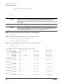
1
Installation Guide
HP bh5700 ATCA 14-Slot Blade Server
First Edition
Manufacturing Part Number : AD171-9604A
June 2006
Printed in the U.S.A.
Legal Notices
The information in this document is subject to change without notice.
Hewlett-Packard makes no warranty of any kind with regard to this document, including, but not limited to,
the implied warranties of merchantability and fitness for a particular purpose. Hewlett- Packard shall not be
held liable for errors contained herein or direct, indirect, special, incidental or consequential damages in
connection with the furnishing, performance, or use of this material.
Restricted Rights Legend. Use, duplication or disclosure by the U.S. Government is subject to restrictions
as set forth in subparagraph (c) (1) (ii) of the Rights in Technical Data and Computer Software clause at
DFARS 252.227-7013 for DOD agencies, and subparagraphs (c) (1) and (c) (2) of the Commercial Computer
Software Restricted Rights clause at FAR 52.227-19 for other agencies.
Information in this document is provided in connection with Intel® products. No license, express or implied,
by estoppel or otherwise, to any intellectual property rights is granted by this document. Except as provided
in Intel’s Terms and Conditions of Sale for such products, Intel assumes no liability whatsoever, and Intel
disclaims any express or implied warranty, relating to sale and/or use of Intel products including liability or
warranties relating to fitness for a particular purpose, merchantability, or infringement of any patent,
copyright or other intellectual property right. Intel products are not intended for use in medical, life saving, or
life sustaining applications. Intel may make changes to specifications and product descriptions at any time,
without notice. HEWLETT-PACKARD COMPANY 3000 Hanover Street Palo Alto, California 94304 U.S.A.
Copyright Notice. Copyright ©2003 Hewlett-Packard Development Company, L.P. Reproduction,
adaptation, or translation of this document without prior written permission is prohibited, except as allowed
under the copyright laws.
Additional Copyright Notices. AdvancedTCA® is a registered trademark of the PCI Industrial Computer
Manufacturers Group. Linux® is a registered trademark of Linus Torvalds.
Revision History
First Edition
2
Initial release, June 2006. P/N is AD171-9604A.
Contents
1. Introduction
Introduction . . . . . . . . . . . . . . . . . . . . . . . . . . . . . . . . . . . . . . . . . . . . . . . . . . . . . . . . . . . . . . . . . . . . . . . .
Overview . . . . . . . . . . . . . . . . . . . . . . . . . . . . . . . . . . . . . . . . . . . . . . . . . . . . . . . . . . . . . . . . . . . . . . . . .
Installation Checklist . . . . . . . . . . . . . . . . . . . . . . . . . . . . . . . . . . . . . . . . . . . . . . . . . . . . . . . . . . . . . . .
Safety Considerations. . . . . . . . . . . . . . . . . . . . . . . . . . . . . . . . . . . . . . . . . . . . . . . . . . . . . . . . . . . . . . .
Communications Interference . . . . . . . . . . . . . . . . . . . . . . . . . . . . . . . . . . . . . . . . . . . . . . . . . . . . . . . .
Intra-building Network Connection Requirements . . . . . . . . . . . . . . . . . . . . . . . . . . . . . . . . . . . . . . .
Electrostatic Discharge Hazard to Equipment . . . . . . . . . . . . . . . . . . . . . . . . . . . . . . . . . . . . . . . . . . .
10
10
14
15
15
15
15
2. Unpacking the 14-Slot Shelf
Unpacking the 14-Slot Shelf . . . . . . . . . . . . . . . . . . . . . . . . . . . . . . . . . . . . . . . . . . . . . . . . . . . . . . . . . . . 18
3. Rack Mounting the 14-Slot Shelf
Rack Mounting the 14-Slot Shelf . . . . . . . . . . . . . . . . . . . . . . . . . . . . . . . . . . . . . . . . . . . . . . . . . . . . . . . 26
Installing the 14-Slot Shelf in a HP EIA Standard Seismic Rack . . . . . . . . . . . . . . . . . . . . . . . . . . . . 26
Mounting the 14-Slot Shelf in a 2-Post Equipment Rack. . . . . . . . . . . . . . . . . . . . . . . . . . . . . . . . . . . 30
4. Connecting Protective Earth Ground and External Power to the Shelf
Connecting Protective Earth Ground and External Power to the Shelf . . . . . . . . . . . . . . . . . . . . . . . . .
Connecting the Shelf to Earth Ground . . . . . . . . . . . . . . . . . . . . . . . . . . . . . . . . . . . . . . . . . . . . . . . . .
Verifying the Power Supply Output. . . . . . . . . . . . . . . . . . . . . . . . . . . . . . . . . . . . . . . . . . . . . . . . . . . .
Connecting the Power and Return Cables. . . . . . . . . . . . . . . . . . . . . . . . . . . . . . . . . . . . . . . . . . . . . . .
34
34
36
37
5. Installing 14-Slot Shelf Components
Installing 14-Slot Shelf Components . . . . . . . . . . . . . . . . . . . . . . . . . . . . . . . . . . . . . . . . . . . . . . . . . . . .
Server Blade Memory Modules . . . . . . . . . . . . . . . . . . . . . . . . . . . . . . . . . . . . . . . . . . . . . . . . . . . . . . .
Removing the DIMMs. . . . . . . . . . . . . . . . . . . . . . . . . . . . . . . . . . . . . . . . . . . . . . . . . . . . . . . . . . . . . . .
Replacing the Memory Modules. . . . . . . . . . . . . . . . . . . . . . . . . . . . . . . . . . . . . . . . . . . . . . . . . . . . . . .
42
42
42
44
6. 14-Slot Shelf Startup
14-Slot Shelf Startup . . . . . . . . . . . . . . . . . . . . . . . . . . . . . . . . . . . . . . . . . . . . . . . . . . . . . . . . . . . . . . . . . 48
Local Serial Console Port Access . . . . . . . . . . . . . . . . . . . . . . . . . . . . . . . . . . . . . . . . . . . . . . . . . . . . . . 48
Determining Firmware Versions . . . . . . . . . . . . . . . . . . . . . . . . . . . . . . . . . . . . . . . . . . . . . . . . . . . . . . 52
Validating and Updating Your Firmware . . . . . . . . . . . . . . . . . . . . . . . . . . . . . . . . . . . . . . . . . . . . . . . 54
Operating Systems Supported by Hewlett-Packard . . . . . . . . . . . . . . . . . . . . . . . . . . . . . . . . . . . . . . . 54
Default Startup VLAN Topology for the 14-Slot Shelf . . . . . . . . . . . . . . . . . . . . . . . . . . . . . . . . . . . . . 55
Enabling Remote Firmware Update and Diagnostic Support for the HP bc2100 ATCA Server Blade .
56
7. A Sample VLAN Topology
A Sample VLAN Topology . . . . . . . . . . . . . . . . . . . . . . . . . . . . . . . . . . . . . . . . . . . . . . . . . . . . . . . . . . . . .
Planning Your Network Topology . . . . . . . . . . . . . . . . . . . . . . . . . . . . . . . . . . . . . . . . . . . . . . . . . . . . .
Building the Sample Topology in the 14-Slot Shelf . . . . . . . . . . . . . . . . . . . . . . . . . . . . . . . . . . . . . . .
Ethernet Switch Blade Port and IPMB Mappings . . . . . . . . . . . . . . . . . . . . . . . . . . . . . . . . . . . . . . . .
Configuring the HP bc2100 ATCA Server Blade Ethernet Interface Connectors. . . . . . . . . . . . . . . .
60
61
65
93
94
3
Contents
Index . . . . . . . . . . . . . . . . . . . . . . . . . . . . . . . . . . . . . . . . . . . . . . . . . . . . . . . . . . . . . . . . . . . . . . 103
4
Tables
Table 1-1. Installation Checklist . . . . . . . . . . . . . . . . . . . . . . . . . . . . . . . . . . . . . . . . . . . . . . . . . . . . .
Table 3-1. Rack Mount Kit, HP bh5700 ATCA 14-Slot Blade Server, (PN Z7678-60275) . . . . . . . .
Table 6-1. Default rc Script VLAN Configuration . . . . . . . . . . . . . . . . . . . . . . . . . . . . . . . . . . . . . . .
Table 6-2. HP bc2100 ATCA Server Blade BIOS Default Port Assignments . . . . . . . . . . . . . . . . . .
Table 7-1. 14-Slot Shelf Server Blade External Ethernet Connections . . . . . . . . . . . . . . . . . . . . . .
14
26
55
56
94
5
Tables
6
Figures
Figure 1-1. HP bh5700 ATCA 14-Slot Blade Server, Basic Configuration . . . . . . . . . . . . . . . . . . . .
Figure 1-2. HP bh5700 ATCA 14-Slot Blade Server (Front View). . . . . . . . . . . . . . . . . . . . . . . . . . .
Figure 1-3. HP bh5700 ATCA 14-Slot Blade Server (Rear View) . . . . . . . . . . . . . . . . . . . . . . . . . . .
Figure 1-4. ESD Wrist Strap Terminal Locations . . . . . . . . . . . . . . . . . . . . . . . . . . . . . . . . . . . . . . .
Figure 2-1. Shipping Carton and Top Foam Cushions Removed . . . . . . . . . . . . . . . . . . . . . . . . . . .
Figure 2-2. Bottom Corrogated Tray Unrolled . . . . . . . . . . . . . . . . . . . . . . . . . . . . . . . . . . . . . . . . .
Figure 2-3. Positioning the Mechanical Lift Under the 14-Slot Shelf . . . . . . . . . . . . . . . . . . . . . . .
Figure 2-4. Pushing the Unit Onto the Mechanical Lift . . . . . . . . . . . . . . . . . . . . . . . . . . . . . . . . . .
Figure 2-5. Ready to Attach the Front and Rear Cable Trays. . . . . . . . . . . . . . . . . . . . . . . . . . . . . .
Figure 2-6. Mounting the Front Cable Tray . . . . . . . . . . . . . . . . . . . . . . . . . . . . . . . . . . . . . . . . . . .
Figure 3-1. Mounting Slide Attached to Cabinet Rails (Rear Hold-down Bracket in Place) . . . . . .
Figure 3-2. Nut Clip, M5x0.8 . . . . . . . . . . . . . . . . . . . . . . . . . . . . . . . . . . . . . . . . . . . . . . . . . . . . . . . .
Figure 3-3. Installing Nut Clip . . . . . . . . . . . . . . . . . . . . . . . . . . . . . . . . . . . . . . . . . . . . . . . . . . . . . .
Figure 3-4. M5x0.8x16, Torx Pan Screw, with Crest Cup Washer. . . . . . . . . . . . . . . . . . . . . . . . . . .
Figure 3-5. Front View, 14-Slot Shelf, Rack Mounting Flanges Attached . . . . . . . . . . . . . . . . . . . .
Figure 3-6. Flange Mounting Positions for 2- and 4-Post Equipment Racks . . . . . . . . . . . . . . . . . .
Figure 4-1. Earth Ground Lugs and PEM Location on Shelf Rear (Numbers 8, 4, & 9) . . . . . . . . .
Figure 4-2. Earth Ground Lug Detail, Shelf Lower Right Rear . . . . . . . . . . . . . . . . . . . . . . . . . . . .
Figure 4-3. Typical High Availability Power Connection Block Diagram. . . . . . . . . . . . . . . . . . . . .
Figure 4-4. PEM Power Lead and Return (RTN) Connections . . . . . . . . . . . . . . . . . . . . . . . . . . . . .
Figure 4-5. Typical PEM Power Cable Connection Layout. . . . . . . . . . . . . . . . . . . . . . . . . . . . . . . .
Figure 5-1. Server Blade with Access Cover Panel Installed . . . . . . . . . . . . . . . . . . . . . . . . . . . . . .
Figure 5-2. Releasing the DIMM from DIMM Socket U5 . . . . . . . . . . . . . . . . . . . . . . . . . . . . . . . . .
Figure 5-3. DIMM Socket Assignments . . . . . . . . . . . . . . . . . . . . . . . . . . . . . . . . . . . . . . . . . . . . . . .
Figure 6-1. RJ-45/DB-9 Adapter Cable, PN A6800-63006 . . . . . . . . . . . . . . . . . . . . . . . . . . . . . . . . .
Figure 6-2. RJ-45/DB-9 Adapter Pin Assignments. . . . . . . . . . . . . . . . . . . . . . . . . . . . . . . . . . . . . . .
Figure 6-3. Shelf Manager Serial Ports on the Alarm Display Panel . . . . . . . . . . . . . . . . . . . . . . . .
Figure 6-4. HP bc2100 ATCA Server Blade Serial Port . . . . . . . . . . . . . . . . . . . . . . . . . . . . . . . . . . .
Figure 6-5. Ethernet Switch Blade Serial Ports . . . . . . . . . . . . . . . . . . . . . . . . . . . . . . . . . . . . . . . . .
Figure 7-1. HP bh5700 ATCA 14-Slot Blade Server. . . . . . . . . . . . . . . . . . . . . . . . . . . . . . . . . . . . . .
Figure 7-2. Ethernet Switch Blade Front Panel . . . . . . . . . . . . . . . . . . . . . . . . . . . . . . . . . . . . . . . . .
Figure 7-3. Simplified Block Diagram of the Sample VLAN Topology . . . . . . . . . . . . . . . . . . . . . . .
Figure 7-4. Identifying 2 RJ-45 Shelf Manager Serial Connectors on the Alarm Display Panel . .
Figure 7-5. RJ-45/DB-9 Console Adapter Cable . . . . . . . . . . . . . . . . . . . . . . . . . . . . . . . . . . . . . . . . .
Figure 7-6. Identifying Jumpers B141 to B144 Installed on ShMM Carrier Board . . . . . . . . . . . . .
Figure 7-7. Ethernet Switch Blade Front Panel Base Serial Ports . . . . . . . . . . . . . . . . . . . . . . . . . .
Figure 7-8. Ethernet Switch Blade Front Panel Fabric Serial Ports. . . . . . . . . . . . . . . . . . . . . . . . .
Figure 7-9. The zre12 Base Interface, Ethernet Switch Blade Front Panel . . . . . . . . . . . . . . . . . . .
Figure 7-10. Ethernet Switch Blade Fabric Connectors. . . . . . . . . . . . . . . . . . . . . . . . . . . . . . . . . . .
Figure 7-11. Configured Sample Network Topology. . . . . . . . . . . . . . . . . . . . . . . . . . . . . . . . . . . . . .
Figure 7-12. Port IPMB Mapping . . . . . . . . . . . . . . . . . . . . . . . . . . . . . . . . . . . . . . . . . . . . . . . . . . . .
11
12
13
16
19
20
21
22
23
24
27
28
28
29
29
31
35
36
37
38
38
43
44
45
48
49
49
50
51
60
62
64
65
66
67
70
70
77
92
93
94
7
Figures
8
1 Introduction
Chapter 1
9
Introduction
Introduction
Introduction
NOTE
There are some current issues with the HP bh5700 ATCA 14-Slot Blade Server. The issues are
in the process of being solved. Please refer to www.docs.hp.com (customer-viewable) to see the
latest list of issues and ways to work through them. The list of issues will be updated
frequently.
This document provides the following information for the Advanced Telecommunications Computer
Architecture (AdvancedTCA or ATCA) Standard, HP bh5700 ATCA 14-Slot Blade Server:
•
An overview of the HP bh5700 ATCA 14-Slot Blade Server.
•
An installation checklist.
•
Safety, communications interference, and electronic discharge considerations.
•
Unpacking the 14-Slot Shelf.
•
Rack mounting the 14-Slot Shelf.
•
Connecting external power to the 14-Slot Shelf.
•
Factory default operating topology.
•
Example VLAN topology configuration.
NOTE
An Installation Checklist is provided in Table 1-1 on page 14. Use this checklist to help ensure
that you follow the proper sequence. Observe all safety procedures while preparing your site for
installation, unpacking, and installing the 14-Slot Shelf.
Overview
The HP bh5700 ATCA 14-Slot Blade Server can be configured with up to fourteen individual blades installed
into the shelf blade cage. For high reliability telecommunications operation, each 14-Slot Shelf must have a
minimum of two matching Ethernet switch blades installed in the blade cage hub slots (physical Slots 6 and
7). Additional blades (processor blades, advanced mezzanine card [AMC] blades, and others) can be installed
in the 14-Slot Shelf as required.
See Figure 1-1 on page 11 for the typical HP bh5700 ATCA 14-Slot Blade Server configuration:
•
One 14-Slot Shelf (blade cage chassis and components)
•
Two Ethernet switch blades
•
Two Intel® Xeon dual processor blades.
The 14-Slot Shelf blade cage chassis and components are defined in Figure 1-2 on page 12 and Figure 1-3 on
page 13.
10
Chapter 1
Introduction
Introduction
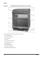
Figure 1-1
Chapter 1
HP bh5700 ATCA 14-Slot Blade Server, Basic Configuration
11
Introduction
Introduction
Figure 1-2
HP bh5700 ATCA 14-Slot Blade Server (Front View)
1
6
7
2
8
3
4
9
10
5
Use the following list to identify the callouts from Figure 1-2:
1. Alarm display panel
2. ATCA 14-Slot backplane
3. Front card cage
4. Air filter
5. Primary Shelf Manager (left)
6. Alarm connector panel
7. Front cable tray
8. Rack mounting flange
9. ESD wrist strap terminal
10. Secondary Shelf Manager (right)
12
Chapter 1
Introduction
Introduction
Figure 1-3
HP bh5700 ATCA 14-Slot Blade Server (Rear View)
5
1
6
2
3
7
8
4
9
Use the following list to identify the callouts from Figure 1-3:
1. Fan tray #2
2. Rear card cage
3. ESD wrist strap terminal
4. Power entry module (PEM B)
5. Fan tray #1
6. Fan tray #0
7. Rear cable tray
8. Shelf ground terminal (M6 studs)
9. Power entry module (PEM A)
Chapter 1
13
Introduction
Introduction
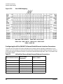
Installation Checklist
This section provides an installation checklist to assist you with preparing the installation site and installing
the 14-Slot Shelf.
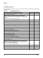
Table 1-1
Installation Checklist
Installation Procedure (See chapters 1 through 5)
In-process
Completed
SITE PREPARATION VERIFIED
WARNING: Observe all electrical safety precautions when
configuring the external power supplies. This is a high voltage
hazard.
External power supplies configuration verified
Site environmental requirements verified
Protective earth ground verified
UNPACKING THE SHELF
Shipping container inspected for damage
All packing material removed from Shelf
Shipping inventory completed
Front and rear cable trays attached to Shelf
RACK MOUNTING THE SHELF
Rack mounting flange configured
Seismic rack mounting procedures completed
POWER CONNECTION
WARNING: Ensure that all power domain circuit breakers are
switched OFF before connecting power and return cables to the
Shelf. This is a high voltage hazard.
Power and return leads connected to PEMs
External power supply voltages verified
Protective earth ground connected to Shelf
14
Chapter 1
Introduction
Introduction
Safety Considerations
All site preparation, installation, and service work on the 14-Slot Shelf must be performed by qualified
personnel.
WARNING
Failure to follow all electrical and mechanical safety precautions in this document
could result in serious personal injury.
Communications Interference
HP system compliance tests are conducted with HP supported peripheral devices and shielded cables, such as
those received with the system. The system meets interference requirements of all countries in which it is
sold. These requirements provide reasonable protection against interference with radio and television
communications.
Installing and using the system in strict accordance with HP instructions minimizes the chances that the
system will cause radio or television interference. However, HP does not guarantee that the system will not
interfere with radio and television reception.
Follow these precautions:
•
Use only shielded cables.
•
Ensure that all cable connector screws are firmly secured.
•
Use only HP supported peripheral devices.
Ensure that all panels and cover plates are secured in place before system operation.
Intra-building Network Connection Requirements
NOTE
To protect against intra-building lighting surges, intra-building network connections must use
shielded cables that are grounded at both ends.
Electrostatic Discharge Hazard to Equipment
HP systems and peripherals contain assemblies and components that are sensitive to electrostatic discharge
(ESD). Carefully observe the precautions and recommended procedures in this guide to prevent component
damage from static electricity.
CAUTION
Wear an ESD wrist strap that is connected to the same ground potential as the unit you are
working on. Connection may be made to any grounded metal assembly in the cabinet. Both you
and the electronic devices must be grounded to avoid damage caused by static discharge. If the
Shelf is not connected to earth ground, protect the Shelf in an ESD-safe working environment
before removing or replacing any field replaceable unit (FRU).
Chapter 1
15
Introduction
Introduction
Follow these ESD precautions:
•
Prepare an ESD-safe work surface large enough to accommodate the FRUs being handled during
servicing. Use a grounding mat and an anti-static wrist strap, such as those included in the ESD Field
Service Kit (A3024-80004).
•
The anti-static bag that encloses FRUs cannot function as a static dissipating mat. Do not use the
anti-static bag for any other purpose than to enclose a product.
•
Treat all assemblies, components, and interface connections as static-sensitive.
•
Keep FRUs in a conductive plastic bag until they are ready to be installed or shipped for repair.
•
Avoid working in carpeted areas, and keep body movement to a minimum while removing and installing
FRUs.
•
Electrostatic discharge wrist strap grounding connection sockets are provided at the following locations
on the 14-Slot Shelf exterior:
— On the front; in the lower left corner, immediately above the Shelf Manager (Figure 1-4).
— On the rear; in the lower left corner, immediately above the power entry module (PEM B) (Figure 1-4).
Figure 1-4
ESD Wrist Strap Terminal Locations
ESD Terminal Socket
ESD Terminal
Socket
16
Chapter 1
2 Unpacking the 14-Slot Shelf
Chapter 2
17
Unpacking the 14-Slot Shelf
Unpacking the 14-Slot Shelf
Unpacking the 14-Slot Shelf
This chapter provides information about unpacking and installing the bundled 14-Slot Shelf.
CAUTION
To minimize any possibility of physical damage to equipment, ensure that floorspace at the
installation site is neat and uncluttered. Ensure that a mechanical lift can be maneuvered in
the area to lift the Shelf from the shipping pallet.
HP shipping containers are designed to protect their contents under normal shipping conditions. After the
equipment arrives at the installation site, carefully inspect each carton for signs of shipping damage. If the
container is damaged, document the damage with photographs and contact the transport carrier immediately.
NOTE
The factory provides an installation warranty that is effective from the time the shipment is
received until Field Services completes the system installation. Please check all equipment and
accessories against the shipping manifest. If any parts or accessories are missing or defective
upon receipt, they will be replaced directly from the factory. To request replacement parts,
contact the HP representative.
Unpack the 14-Slot Shelf by using the following steps:
Step 1. Use a sharp knife or scissors to cut away any shrink-wrap packaging material that covers the
shipping package.
WARNING
All poly strap shipping bands that secure the 14-Slot Shelf packaging are
stretched tight and are under tension. Wear eye protection to prevent
possible eye injury when cutting the strap, as the strap tension is released,
and strap ends recoil outward.
CAUTION
Always cut any shrink wrapping material away from the packing carton; do not
physically pull and tear the fabric. Physically pulling the shrink wrapping from the
shipping carton without cutting it first may create an electrostatic charge that could
damage electronic equipment.
Step 2. Follow the warning above and cut the packaging poly strap banding on the 14-Slot Shelf.
Step 3. Remove the shipping carton and the interior top foam cushions, leaving the 14-Slot Shelf sitting in
the corrugated tray. See Figure 2-1 on page 19.
18
Chapter 2
Unpacking the 14-Slot Shelf
Unpacking the 14-Slot Shelf
Figure 2-1 Shipping Carton and Top Foam Cushions Removed
Step 4. Remove both the corrugated roll-up spacer and the carton containing the front and rear cable trays
along with other important documentation. These are located to either side of the unit. See
Figure 2-1.
Step 5. Unroll the bottom corrugated tray. See Figure 2-2 on page 20.
Chapter 2
19
Unpacking the 14-Slot Shelf
Unpacking the 14-Slot Shelf
Figure 2-2 Bottom Corrogated Tray Unrolled
Step 6. Position the mechanical lift as shown in Figure 2-3 on page 21. The lift should be in line or slightly
below the top surface of the bottom foam cushions. If needed, slide the cushions that the unit is
resting on outward, a little closer to the edge of the pallet, to allow the lift to slide under the unit.
20
Chapter 2
Unpacking the 14-Slot Shelf
Unpacking the 14-Slot Shelf
Figure 2-3 Positioning the Mechanical Lift Under the 14-Slot Shelf
Step 7. Push the 14-Slot Shelf onto the mechanical lift. See Figure 2-4 on page 22.
Chapter 2
21
Unpacking the 14-Slot Shelf
Unpacking the 14-Slot Shelf
Figure 2-4 Pushing the Unit Onto the Mechanical Lift
Step 8. Slide the bag down around the server. See Figure 2-5 on page 23. Install cable trays and proceed
with the remainder of the installation.
22
Chapter 2
Unpacking the 14-Slot Shelf
Unpacking the 14-Slot Shelf
Figure 2-5Ready to Attach the Front and Rear Cable Trays
Step 9. Locate the front and rear cable trays from the accessory package and mount to the Shelf. To mount
the cable trays, locate and remove the existing cable tray chassis screws that match the mounting
holes for each tray. Reuse these screws to mount the two cable trays. See Figure 2-6 on page 24.
The 14-Slot Shelf is now ready for equipment rack mounting.
Chapter 2
23
Unpacking the 14-Slot Shelf
Unpacking the 14-Slot Shelf
Figure 2-6 Mounting the Front Cable Tray
24
Chapter 2
3 Rack Mounting the 14-Slot Shelf
Chapter 3
25
Rack Mounting the 14-Slot Shelf
Rack Mounting the 14-Slot Shelf
Rack Mounting the 14-Slot Shelf
The HP bh5700 ATCA 14-Slot Blade Server is designed to mount in a 19 in. (48.26 cm) wide, 23.62 in (600
mm) deep, Electronics Industry Alliance (EIA), seismic-rated HP rack. The 14-Slot Shelf is shipped with the
rack mounting flanges correctly positioned for mounting into a 4-post seismic-rated equipment rack. This
chapter provides detailed procedures for completing the rack mount installation.
Installing the 14-Slot Shelf in a HP EIA Standard Seismic Rack
The ATCA 14-Slot Shelf 600 mm EIA Seismic Rack Mount Kit provided with your HP Seismic Rack includes
all items required to mount the HP bh5700 ATCA 14-Slot Blade Server into the rack. See Table 3-1 for the
contents of the Rack Mount Kit.
Table 3-1
Rack Mount Kit, HP bh5700 ATCA 14-Slot Blade Server, (PN
Z7678-60275)
Item Reference
Description
#1, Figure 3-1
Mounting Slide, Rack Left Side (PN Z7678-00290), 1 each
#2, Figure 3-1
Mounting Slide, Rack Right Side (PN Z7678-00301), 1 each
#3, Figure 3-1
Rear Hold-down bracket, (PN Z7678-00291), 2 each (not
included in this release)
Hardware Kit (PN Z7678-80075), 1 each
#4, Figure 3-1
Nut clip, M5x0.8, 16 each
#5, Figure 3-1
Screw, M5x0.8x16 Torx pan with crest cup washer, 16 each
#6, Figure 3-1
Screw, M5x0.8x10 Torx pan with crest cup washer, 4 each
NOTE
26
The rear hold-down brackets (#3, Figure 3-1) are not included with this product release.
Chapter 3
Rack Mounting the 14-Slot Shelf
Rack Mounting the 14-Slot Shelf
Figure 3-1
Mounting Slide Attached to Cabinet Rails (Rear Hold-down Bracket in
Place)
(not included in this release)
IMPORTANT Before installing the Rack Mount Kit, ensure there will be adequate vertical space to install the
14-Slot Shelf (13U chassis height) in addition to other equipment installed.
To install the 14-Slot Shelf into the EIA Seismic rack, complete the following steps:
Step 1. Determine where the 14-Slot Shelf chassis will be installed within the seismic rack.
Step 2. Install two nut-clips (Figure 3-2 and item 4, Table 3-1) onto the front cabinet rail in the location
where the right mounting slide will be attached (Figure 3-1). Ensure proper spacing of the nut-clips
for the mounting slide attachment holes.
Chapter 3
27
Rack Mounting the 14-Slot Shelf
Rack Mounting the 14-Slot Shelf
Figure 3-2Nut Clip, M5x0.8
Figure 3-3Installing Nut Clip
IMPORTANT The right and left rack mounting slides will support the weight of the 14-Slot Shelf
when mounted in the rack.
Step 3. Install two nut-clips onto the rear cabinet rail in positions that correspond to those installed in step
2 on the front cabinet rail. These nut-clips will be used to attach the rear of the right mounting slide
(see note below).
Step 4. Install the four nut-clips required to attach the left mounting slide as a mirror image of the right
mounting slide (installed in steps 2 and 3).
Step 5. Using four M5x0.8x16 screws , attach the right mounting slide to the front and rear cabinet rails as
shown in Figure 3-1 on page 27. Use a Torx drive torque wrench to tighten each screw to 36
in-pounds (4.067 N-m).
28
Chapter 3
Rack Mounting the 14-Slot Shelf
Rack Mounting the 14-Slot Shelf
Figure 3-4M5x0.8x16, Torx Pan Screw, with Crest Cup Washer
Step 6. Using four M5x0.8x16 screws (Figure 3-4), attach the left mounting slide to the front and rear left
cabinet rails as a mirror image of the installed right mounting slide shown in Figure 3-1 on
page 27. Use a Torx drive torque wrench to tighten each screw to 36 in-pounds (4.067 N-m).
Step 7. On the right and left front cabinet rail, attach four nut-clips on each rail above the installed right
mounting slides (Figure 3-1 on page 27) that will match the mounting holes in the 14-Slot Shelf
rack mounting flanges (Figure 3-5).
Figure 3-5Front View, 14-Slot Shelf, Rack Mounting Flanges Attached
Rack Mount
Flange
Rack Mount
Flange
Step 8. Verify that the 14-Slot Shelf is completely unpacked and its rack mounting flanges are configured
for installation into the 4-post seismic rack (see chapter 2, Unpacking the 14-Slot Shelf).
Chapter 3
29
Rack Mounting the 14-Slot Shelf
Rack Mounting the 14-Slot Shelf
WARNING
A 14-Slot Shelf weighs from 62.6 kg (138 lbs) for the basic configuration to
90 kg (200 lbs) with the blade cage fully populated. This is a pinch, crush,
and heavy lift hazard.
Step 9. Place the 14-Slot Shelf on a portable mechanical lift device that can be used to elevate and hold the
Shelf in place while it is being installed into the seismic rack.
Step 10. Position the portable lift and 14-Slot Shelf directly in front of the seismic rack, with the rear of the
Shelf facing the rack.
Step 11. Raise the Shelf with the lift until the bottom of the 14-Slot Shelf is even with the horizontal surface
of the right and left seismic rack mounting slides installed earlier in the seismic rack.
Step 12. Push the 14-Slot Shelf from the portable lift onto the two mounting slides in the seismic rack until
the rack mounting flanges on the front of the Shelf meet the right and left front rails of the seismic
rack. See Figure 3-5.
Step 13. On the 14-Slot Shelf rack mounting flanges (Figure 3-5), insert the remaining eight M5x0.8x16
screws through the mounting flange holes and into the nut-clips installed previously on the front
rails. Use a Torx drive torque wrench to tighten each screw to 36 in-pounds (4.067 N-m).
CAUTION
Ensure that filler panels are installed in all empty blade cage slots, front and rear.
Missing filler panels or other openings in the 14-Slot Shelf chassis may cause
equipment damage due to cooling fan air flow disruption. This is an equipment
overheating hazard.
Step 14. This completes the 14-Slot Shelf seismic rack installation process. You are now ready to connect
system power and protective ground to the 14-Slot Shelf, as shown in chapter 4.
Mounting the 14-Slot Shelf in a 2-Post Equipment Rack
WARNING
A 14-Slot Shelf weighs from 62.6 kg (138 lbs) for the basic configuration to 90 kg (200
lbs) with the blade cage fully populated. Remove all installed blades, fan trays, and
power entry modules (PEMs) before attempting to move the 14-Slot Shelf by hand.
This is a pinch, crush, and heavy lift hazard.
IMPORTANT Contact Hewlett Packard for all other information about installing the HP bh5700 ATCA
14-Slot Blade Server into a non-standard or non-Hewlett Packard supported rack.
The 14-Slot Shelf can also be mounted into a 2-post, 48.26 cm (19 in) non-seismic-rated rack. The HP bh5700
ATCA 14-Slot Blade Server rack mounting flanges on each side of the 14-Slot Shelf must be repositioned to
mount in a 2-post rack. See the following steps to complete:
Step 1. On the 14-Slot Shelf, remove the two rack mounting flanges from the 4-post mounting position by
first removing the lower two screws that secure each flange to the Shelf side panels (see
Figure 3-6).
30
Chapter 3
Rack Mounting the 14-Slot Shelf
Rack Mounting the 14-Slot Shelf
Figure 3-6Flange Mounting Positions for 2- and 4-Post Equipment Racks
Shelf Front
Step 2. Slide each flange downward until the flange drops out of the five retaining clips that hold the
flanges to the side panels.
Step 3. Reposition each flange over the five retaining clips for the 2-post mounting position (Figure 3-6),
with the clips protruding into the openings in the flange.
Step 4. Slide each flange upward until the flanges are securely seated under the retaining clips.
NOTE
The rack mounting flanges remain vertical for the 2-post rack mount. They are
positioned approximately 5 in. behind the 4-post mount location of the shelf. See
Figure 3-6.
Step 5. On the 14-Slot Shelf, secure the flange at the upper screw holes using the two screws removed from
the bottom of the flange of the 4-post mounting position. Repeat steps 1—5 for other side flange.
Chapter 3
31
Rack Mounting the 14-Slot Shelf
Rack Mounting the 14-Slot Shelf
32
Chapter 3
4 Connecting Protective Earth Ground and
External Power to the Shelf
Chapter 4
33
Connecting Protective Earth Ground and External Power to the Shelf
Connecting Protective Earth Ground and External Power to the Shelf
Connecting Protective Earth Ground and External Power to the Shelf
This chapter provides information on connecting protective earth ground and external system power to the
installed 14-Slot Shelf.
WARNING
Disconnect all power cords to completely remove power. This is a shock hazard.
IMPORTANT Overcurrent protection for the system must be provided at the installation site at not less than
125% of the load for each supply circuit. Due to safety issues when servicing the system, only
one blade should be removed at a time and any slots not containing a blade must have a cover
plate installed.
NOTE
System DC power requirements are located on the side of the ATCA chassis. HP PN:
AD171-2000A on the power label is equivalent to the FCLSB-0602.
Connecting the Shelf to Earth Ground
WARNING
Protective ground must be connected to the 14-Slot Shelf before connecting any
external power. This is a high voltage hazard if not connected.
On the right-rear of the 14-Slot Shelf, connect an earth grounding cable to the two grounding lugs located
above the power entry module A (PEM A). See Figure 4-1 and Figure 4-2.
Recommended minimum specifications for the grounding cable and its connection include the following:
•
Recommended Minimum Wire Size: AWG6
•
Recommended Terminals: Use only double lug terminals, with a 45o angle.
34
Chapter 4
Connecting Protective Earth Ground and External Power to the Shelf
Connecting Protective Earth Ground and External Power to the Shelf
Figure 4-1
Earth Ground Lugs and PEM Location on Shelf Rear (Numbers 8, 4, & 9)
55
1
2
6
7
3
8
4
9
Use the following list to identify the callouts from Figure 4-1:
1. Fan tray #2
2. Rear card cage
3. ESD wrist strap terminal
4. Power entry module (PEM B)
5. Fan tray #1
6. Fan tray #0
7. Rear cable tray
8. Shelf ground terminal
9. Power entry module (PEM A)
Chapter 4
35
Connecting Protective Earth Ground and External Power to the Shelf
Connecting Protective Earth Ground and External Power to the Shelf
Figure 4-2
Earth Ground Lug Detail, Shelf Lower Right Rear
Earth Ground Lugs
Verifying the Power Supply Output
WARNING
Observe all electrical hazard safety procedures when verifying the external power
supply voltages. Failure to comply can result in personal injury.
CAUTION
All input power and return wiring should be specified, configure, and installed by a qualified
electrician in order to prevent damage to the equipment.
CAUTION
Output voltages from the external power supply must be verified before power leads are
connected to the 14-Slot Shelf PEMs. Failure to verify can damage the Shelf and will require
replacement of affected components.
Measure the output voltage between each output power lead and earth ground on the external power
supplies. The supplied voltage must be between -37 and -72 VDC (Nominal -48V).
See Figure 4-3 for a simplified block diagram of a typical external power supply configuration.
36
Chapter 4
Connecting Protective Earth Ground and External Power to the Shelf
Connecting Protective Earth Ground and External Power to the Shelf
Figure 4-3
Typical High Availability Power Connection Block Diagram
Minimum Power Connection Cable Specifications
CAUTION
All input power and return wiring should be specified, configure, and installed by a qualified
electrician in order to prevent damage to the equipment.
The following are the recommended minimum specifications for input power and return cables:
•
Cable Size:
— Diameter of 6 mm2 respective, AWG10.
— Maximum length of 2.5 to 3.0m.
— Suitable for 30A at 50oC ambient temperature.
•
Required Terminals: Use ring terminals for screw M3.5. Maximum outside diameter is 9.5 mm.
Chapter 4
37
Connecting Protective Earth Ground and External Power to the Shelf
Connecting Protective Earth Ground and External Power to the Shelf
Connecting the Power and Return Cables
WARNING
Ensure that each power domain supply circuit breaker is switched OFF while
completing the following power connection procedure. Failure to comply can result
in personal injury.
To connect external power and voltage return (VRTN) leads to the 14-Slot Shelf, complete the following steps:
Step 1. On the rear of the 14-Slot Shelf, remove the PEM A Terminal Block Cover and connect the four
PEM A independent domain power cables and four return lines as shown in Figure 4-4. The four
cables and terminals on the left are the power domain leads, and the four cables and terminals on
the right are the return lines for the PEM.
Figure 4-4 PEM Power Lead and Return (RTN) Connections
Power Lead
Cables
Return Cables
(Black)
CAUTION
Make certain to connect matching power supply domain 1 lead to power domain 1
terminal lug on the PEM, matching lead 2 to terminal lug 2, and so on. Also ensure
that power domain VRTN lines are matched to respective connections on each PEM.
See Figure 4-4 and Figure 4-5.
NOTE
In a typical telecommunications environment, the VRTN path of the -48 VDC supply
is grounded to protective earth (PE) of the building.
Step 2. Replace and secure the PEM A terminal block cover when all power leads and VRTN lines have
been attached.
Step 3. Remove the PEM B terminal block cover (see Figure 4-5) and connect the four PEM B independent
domain power leads and VRTN lines from the redundant power supply, using the same procedure
as above, for PEM A.
38
Chapter 4
Connecting Protective Earth Ground and External Power to the Shelf
Connecting Protective Earth Ground and External Power to the Shelf
Figure 4-5 Typical PEM Power Cable Connection Layout
Step 4. On PEM B, replace and secure the PEM B terminal block cover.
WARNING
When external power is applied, the 14-Slot Shelf is energized at all times.
Power to the 14-Slot Shelf is controlled only from the external power
source, and cannot be switched off at the 14-Slot Shelf. Failure to observe
can result in personal injury.
Step 5. The 14-Slot Shelf is now ready to receive system power.
Chapter 4
39
Connecting Protective Earth Ground and External Power to the Shelf
Connecting Protective Earth Ground and External Power to the Shelf
40
Chapter 4
5 Installing 14-Slot Shelf Components
Chapter 5
41
Installing 14-Slot Shelf Components
Installing 14-Slot Shelf Components
Installing 14-Slot Shelf Components
This chapter provides information for installing memory modules into the HP bc2100 ATCA Server Blade.
Server Blade Memory Modules
The HP bc2100 ATCA Server Blade Dual In-line Memory Modules (DIMMs) are always installed in pairs.
Each individual DIMM within a pair must also be identical in storage capacity, revision, and part number.
The current DIMM configurations supported by Hewlett-Packard include any of the following:
•
Two 1–GB DIMMs (2 GB)
•
Four 1–GB DIMMs (4 GB)
•
Two 2–GB DIMMs (4 GB)
•
Four 2–GB DIMMs (8 GB)
This section provides information on removing and replacing the DIMMs in an HP bc2100 ATCA Server
Blade.
Removing the DIMMs
To remove mounted DIMMs from the Server Blade, complete the following steps:
CAUTION
Observe all ESD safety precautions while completing this procedure. Failure to follow ESD
saftey precautions could result in damage to the 14-Slot Shelf and equipment.
Step 1. Following hot-swap procedures, remove the HP bc2100 ATCA Server Blade from the 14-Slot Shelf.
Step 2. Lay the Server Blade flat on an anti-static working surface and position the blade front panel
facing you. Ensure that the backplane connector (blue color) is facing away from you and is on the
right side of the blade as it lays flat (see Figure 5-1 on page 43).
42
Chapter 5
Installing 14-Slot Shelf Components
Installing 14-Slot Shelf Components
Figure 5-1 Server Blade with Access Cover Panel Installed
Step 3. Remove the countersunk retaining screws that secure the blade access cover panel and remove the
cover panel. Set the cover panel and retaining screws aside for reuse.
Step 4. To release the DIMM from its socket, pull the sockets end levers away from the memory module
(see Figure 5-2 on page 44).
Chapter 5
43
Installing 14-Slot Shelf Components
Installing 14-Slot Shelf Components
Figure 5-2 Releasing the DIMM from DIMM Socket U5
Step 5. Grasp the memory module and remove by angling away from the socket. Place the DIMM in a
static-safe location.
Step 6. Repeat steps 4 and 5 to remove any remaining DIMMs. Place each memory module in a static-safe
location.
Replacing the Memory Modules
CAUTION
Observe all ESD safety precautions while completing this procedure. Failure to follow ESD
safety precautions can result in damage to the 14-Slot Shelf and equipment.
CAUTION
Each DIMM is keyed . Ensure the memory module is indexed correctly before seating into a
DIMM socket. Failure to observe will damage the DIMM and the socket, requiring replacement
of the Server Blade and the affected DIMM.
44
Chapter 5
Installing 14-Slot Shelf Components
Installing 14-Slot Shelf Components
CAUTION
The DIMMs must be replaced in pairs. Each individual DIMM must be identical in storage
capacity, revision, and part number. The current DIMM configurations supported by HP
include any of the following:
•
Two 1–GB DIMMs (2 GB)
•
Four 1–GB DIMMs (4 GB)
•
Two 2–GB DIMMs (4 GB)
•
Four 2–GB DIMMs (8 GB)
IMPORTANT DIMM sockets U5 and U12 are always populated. See Figure 5-3.
Figure 5-3
Chapter 5
DIMM Socket Assignments
45
Installing 14-Slot Shelf Components
Installing 14-Slot Shelf Components
If loading one DIMM pair only, begin by loading the selected DIMM into DIMM socket U12 first. This will
ease the installation of the second DIMM into DIMM socket U5.
If you are populating all four DIMM sockets, load DIMM socket U17 first. Load DIMM socket U15 next before
loading DIMM socket U12 and finish by loading DIMM socket U5 last.
Step 1. Angle a selected DIMM over an empty DIMM socket.
Step 2. Correctly orient the key and press down evenly to seat the DIMM into the socket.
Step 3. The DIMM socket levers will rise to secure the DIMM. Pull each lever against the side of the DIMM
to ensure it is seated.
Step 4. Repeat steps 1 through 3 to load the remaining DIMM(s).
Step 5. Reinstall the Server Blade access cover. Fasten the cover with the screws retained earlier.
This completes the DIMM replacement procedure.
46
Chapter 5
6 14-Slot Shelf Startup
Chapter 6
47
14-Slot Shelf Startup
14-Slot Shelf Startup
14-Slot Shelf Startup
This chapter provides information required to:
•
Access the local serial console ports of the HP bh5700 ATCA 14-Slot Blade Server.
•
Determine firmware release versions for the major components in the 14-Slot Shelf.
•
Validate and update the 14-Slot Shelf firmware.
•
Choose and install an operating system on the HP bc2100 ATCA Server Blades in your HP bh5700 ATCA
14-Slot Blade Server.
•
Understand the default startup virtual local area network (VLAN) topology that was embedded before
your 14-Slot Shelf was shipped from the factory.
•
Enable remote firmware update and diagnostic support for the HP bc2100 ATCA Server Blade.
Local Serial Console Port Access
Local serial console access to the major components of the 14-Slot Shelf is provided by a series of serial ports
on the front of the shelf for the ShMMs, and on the front panel of each installed blade. You must use an
RJ-45/DB-9 adapter cable (Figure 6-1) in combination with a modem eliminator cable that has a DB-9 female
connector on each end in order to connect your terminal or laptop computer to any of the local serial ports on
the 14-Slot Shelf and installed components.
Figure 6-1
RJ-45/DB-9 Adapter Cable, PN A6800-63006
Pin assignments for the RJ-45/DB-9 Adapter Cable connectors are provided in Figure 6-2 on page 49.
48
Chapter 6
14-Slot Shelf Startup
14-Slot Shelf Startup
Figure 6-2
RJ-45/DB-9 Adapter Pin Assignments
The Shelf Manager (ShMM) Serial Ports
A serial RJ-45 port to each ShMM is located on the Alarm Display Panel. The Alarm Display Panel is located
on the upper-left front of the 14-Slot Shelf, and contains one serial port for the left ShMM and a second port
for the right ShMM (see Figure 6-3). The RJ-45/DB-9 adapter cable connects into these ports.
Figure 6-3
Shelf Manager Serial Ports on the Alarm Display Panel
The HP bc2100 ATCA Server Blade Serial Port
An RJ-45 serial port is provided on the front panel of each HP bc2100 ATCA Server Blade, as shown in
Figure 6-4 on page 50. The RJ-45/DB-9 adapter cable connects into this port.
Chapter 6
49
14-Slot Shelf Startup
14-Slot Shelf Startup
Figure 6-4
HP bc2100 ATCA Server Blade Serial Port
The Ethernet Switch Blade Serial Ports
A separate RJ-45 serial port is provided for both base and fabric access on the front panel of each Ethernet
Switch Blade. As shown in Figure 6-5 on page 51, the base serial port is the first port at the top of the base
port series, and the fabric serial port is the fist port at the top of the fabric port series. The RJ-45/DB-9
adapter cable connects into these ports for local console access.
50
Chapter 6
14-Slot Shelf Startup
14-Slot Shelf Startup
Figure 6-5
Chapter 6
Ethernet Switch Blade Serial Ports
51
14-Slot Shelf Startup
14-Slot Shelf Startup
Determining Firmware Versions
Before beginning normal operation with your HP bh5700 ATCA 14-Slot Blade Server, you should determine
the version of the firmware currently installed within each major component of your 14-Slot Shelf, including
each ShMM, each HP bc2100 ATCA Server Blade, and each Ethernet Switch Blade. When you have
determined the actual firmware release version for each major component, you can then validate your
firmware by comparing it to the versions currently available from HP, and updating your firmware where
needed.
The ShMM Firmware
To determine the release date and version of the firmware in a ShMM, complete the following:
Step 1. Ensure that power is applied to the 14-Slot Shelf.
Step 2. Connect your PC or laptop computer to the serial port for the respective ShMM (located on the alert
display panel). Activate a terminal emulator (9600 baud, 8 data bits, no parity, 1 stop bit) on your
PC or laptop computer, and bring up the ShMM console screen.
Step 3. From the Linux prompt (#) on the ShMM console screen, enter the following command and record
the printed results as shown in the following example:
# version -c
Active firmware revisions:
--------------------------U-Boot 1.1.2
MIPS Linux-2.4.26
63998-04957.RFS
Alternate firmware revisions
---------------------------U-Boot 1.1.2
MIPS Linux-2.4.26
63998-04957.RFS
#
Step 4. Record this firmware information received for the first ShMM, making certain to note which ShMM
this particular firmware data is for.
Step 5. Repeat this procedure for the other ShMM in your 14-Slot Shelf and record that data, making
certain to identify which ShMM the data is for. Set these recorded data aside to be used to validate
your firmware against the most current release.
The HP bc2100 ATCA Server Blade Firmware
To determine the release date and version of the firmware in a Server Blade, complete the following:
Step 1. Ensure that power is applied to the 14-Slot Shelf.
52
Chapter 6
14-Slot Shelf Startup
14-Slot Shelf Startup
Step 2. Connect your PC or laptop computer to the Server Blade serial port, activate a terminal emulator
(9600 baud, 8 data bits, no parity, 1 stop bit) on your PC or laptop computer, and access the Server
Blade console screen.
Step 3. With the console screen displayed, cause the Server Blade to reboot. To cause a reboot you can
either cycle power to the 14-Slot Shelf, or remove and reinstall (following hot swap procedures) the
respective Server Blade.
Approximately 17 seconds following the start of the boot process, the first Server Blade BIOS
message will appear on the console display as the BIOS begins to execute.
Step 4. Interrupt the BIOS execution by entering the delete character from your laptop computer or PC
keyboard. This will halt the BIOS execution and display the main BIOS screen.
Step 5. Record the following information from the main BIOS screen:
AMIBIOS: <Version>
From the Advanced->System Management screen, record the following information:
BMC Device ID
BMC Firmware Revision
BMC Revision
Step 6. Set this recorded information aside, making certain to note which Server Blade the information
relates to.
Step 7. Repeat this procedure for each HP bc2100 ATCA Server Blade installed in the 14-Slot Shelf.
Step 8. Set these recorded data aside to be used to validate your firmware against the most current release.
Ethernet Switch Blade Firmware
Each Ethernet Switch Blade has separate firmware for the base and the fabric sections of the Switch Blade.
There are also separate serial ports for the base and fabric sections, which must be queried individually in
order to determine both the installed base and fabric firmware release version.
To determine the release date and version of the base and fabric firmware in a Server Blade, complete the
following:
Step 1. Ensure that power is applied to the 14-Slot Shelf.
Step 2. Connect your PC or laptop computer to either the base or fabric serial port for the respective Switch
Blade. Note that base and fabric each have separate firmware that must be accessed through
separate serial ports.
Step 3. Activate a terminal emulator (9600 baud, 8 data bits, no parity, 1 stop bit) on your PC or laptop
computer, and bring up the Switch Blade console screen.
IMPORTANT Firmware versions must be recorded for both the base and fabric component of each Switch
Blade, as shown next.
Step 4. From the OpenArchitect Linux prompt ([ZX6000-OA3.2.2j]#), enter the following commands and
record the firmware version that is returned (as shown in the following examples):
•
Chapter 6
For IPMC firmware (applies to base switch component only):
53
14-Slot Shelf Startup
14-Slot Shelf Startup
[ZX6000-OA3.2.2j]# zreg -n -v VP
•
For ZMON(/Sparky) firmware (repeat for both base and fabric switch components):
[ZX6000-OA3.2.2j]# zreg -n -v VZ
4.45
•
For OpenArchitect firmware (repeat for base and fabric component, and note you can only
display the active or booted revision, not the alternate version or flash):
[ZX6000-OA3.2.2j]# zreg -n -v V6
3.2.2 build j
Step 5. Repeat this procedure for the base and fabric component for both Ethernet Switch Blades in the
14-Slot Shelf.
Step 6. Set these recorded data aside to be used to validate your firmware against the most current release.
Validating and Updating Your Firmware
To validate the versions of firmware, and to determine the most recent release of firmware for your 14-Slot
Shelf and its components, complete the following steps:
Step 1. Go to the http://www.hp.com URL.
Step 2. Click on the Software & Driver Downloads link.
Step 3. Under the Support for Your Products link, go to the Select a task and enter a product name/number
box and enter bh5700 in the blank text box. Left click the small double arrow to the right of the text
box.
Step 4. In the resulting Product search results window, choose the appropriate operating system (if
required). The available firmware releases are listed by date.
Step 5. Firmware versions for the components in the 14-Slot Shelf are listed in the Release Notes for each
firmware release. You must compare your installed version with this information to determine if
you have the latest firmware installed on your system. See “Determining Firmware Versions” on
page 52 for information on determining the firmware version currently installed on your 14-Slot
Shelf.
CAUTION
Do not automatically update your 14-Slot Shelf firmware without close analysis of your
specific configuration and application. Your 14-Slot Shelf may require that you retain an
earlier firmware release for some components or applications. Failure to comply can result
in a loss of firmware data.
NOTE
Refer to the release notes supplied with each firmware release for detailed firmware update
procedures.
Operating Systems Supported by Hewlett-Packard
Specified versions of the Linux Operating System are supported by HP for the HP bh5700 ATCA 14-Slot
Blade Server Ethernet Switch Blade. Supported versions include Red Hat and Debian GNU, as follows:
54
Chapter 6
14-Slot Shelf Startup
14-Slot Shelf Startup
Red Hat RHEL AS, Version 4, Update 3 (HP certified on the HP bh5700 ATCA 14-Slot Blade Server) Available directly from Red Hat.
For information about additional versions of Red Hat that have been certified on ATCA by HP since
publication of this document, see the HP Advanced Telecom Computing Architecture (HP ATCA) - Support
Notes for Installing and Using Red Hat, available from HP at: http://www.docs.hp.com.
Debian GNU/Linux with HP Telco Extensions (Debian HPTE) - Available from HP on a per-customer basis
through HP development and support services.
For information about installing Linux on an HP bh5700 ATCA 14-Slot Blade Server Server Blade, refer to
the following HP documentation:
For Red Hat, see the HP Advanced Telecom Computing Architecture (HP ATCA) - Support Notes for Installing
and Using Red Hat, available from HP at: http://www.docs.hp.com.
For Debian HPTE, see the Debian GNU/Linux with HP Telco Extensions Version 2.0 on HP Advanced
Telecom Computing Architecture (HP ATCA) - Installation Guide, available from HP upon request.
Default Startup VLAN Topology for the 14-Slot Shelf
The HP bh5700 ATCA 14-Slot Blade Server is configured at the factory so that the Ethernet Switch Blade
default Virtual Local Area Network (VLAN) topology incorporates all Switch Blade base ports into one VLAN,
and all Switch Blade fabric ports into a separate VLAN. This chapter provides information on the default
boot-up configurations for the HP bh5700 ATCA 14-Slot Blade Server Ethernet Switch Blades, the HP bc2100
ATCA Server Blades, and the Shelf Managers (ShMMs).
CAUTION
Failure to ensure configuration of the 14-Slot Shelf VLAN topology before connecting the
14-Slot Shelf to a functioning network could cause network failure or loss of data. Ensure that
your HP bh5700 ATCA 14-Slot Blade Server is configured with a VLAN topology that is
compatible with your existing network before connecting the shelf. Chapter 6, A Sample VLAN
Topology, provides information on planning and configuring a robust VLAN Topology for your
HP bh5700 ATCA 14-Slot Blade Server.
Shelf Manager Startup Configuration
The Shelf Managers (ShMMs) have been configured at the factory as part of the default VLAN topology for
your 14-Slot Shelf. They require no further configuration in order to use the default topology. The default IP
address on the ShMMs for the eth 0 port is 10.0.0.52 for the active ShMM, and 10.0.0.53 for the backup.
The eth1 port does not have a default configuration.
Ethernet Switch Blade Startup Configuration
At power on, the Ethernet Switch Blades boots up using two default factory-configured rc scripts contained in
the /etc/rcZ.d directory of the Ethernet Switch Blade to configure each side of the switches. One default rc
script configures the base ports on each switch while the other configures the fabric ports. The result is a
basic VLAN topology for your 14-Slot Shelf that consists of two basic VLANs, each with an assigned IP
address: one VLAN for all base ports and another VLAN for all fabric ports for each Ethernet Switch Blade,
as shown in Table 6-1.
Table 6-1
Default rc Script VLAN Configuration
Section
IP Address
VLAN Ports
Base
10.0.0.42
zre 0 to zre 22 (zre 23 reserved for interswitch link)
Chapter 6
55
14-Slot Shelf Startup
14-Slot Shelf Startup
Table 6-1
Default rc Script VLAN Configuration (Continued)
Section
IP Address
VLAN Ports
Fabric
10.0.1.42
zre 0 to zre 50 (zre 51 reserved for interswitch link)
NOTE
A sample alternative Ethernet Switch Blade VLAN configuration is provided in Chapter 6. It
allows you to reconfigure your default VLAN topology into a more extensive and nontrivial
bootup VLAN topology if desired. Additional examples are also located on the Ethernet Switch
Blade at /etc/rcZ.d/examples.
HP bc2100 ATCA Server Blade Startup Configuration
The factory default connection of the Server Blade port Gigabit Ethernet (GE) slots are listed in Table 6-2 and
defines if they are enabled or disabled at preboot execution environment (PXE). The Server Blade default
BIOS configuration (given in Table 6-2) connects the four Server Blade fabric ports to the Ethernet Switch
Blades via the 14-Slot Shelf backplane.
Table 6-2
HP bc2100 ATCA Server Blade BIOS Default Port Assignments
HP bc2100 ATCA Server Blade Port
Ethernet Switch Blade Connection
Port 0, GE Slot 100 (enabled at PXE Boot)
Base Interface to Slot 7
Port 1, GE Slot 101 (enabled at PXE Boot)
Base Interface to Slot 8
Port 2, GE Slot 200 (not enabled at PXE Boot)
Fabric Interface to Slot 7, Port 0
Port 3, GE Slot 201 (not enabled at PXE Boot)
Fabric Interface to Slot 8, Port 0
Port 4, GE Slot 300 (not enabled at PXE Boot)
Fabric Interface to Slot 7, Port 1
Port 5, GE Slot 301 (not enabled at PXE Boot)
Fabric Interface to Slot 8, Port 1
NOTE
You must reconfigure the default HP bc2100 ATCA Server Blade BIOS in order for the PXE
Boot process to enable server ports 2 through 5. Use the procedure described in “The HP
bc2100 ATCA Server Blade Firmware” on page 52, steps 1 – 4 to access the BIOS main screen.
Enabling Remote Firmware Update and Diagnostic Support for the HP bc2100
ATCA Server Blade
CAUTION
Ensure that the VLAN topology of your HP bh5700 ATCA 14-Slot Blade Server includes access
to your remote preboot execution environment (PXE) server before enabling this remote access
feature. Failure to comply can result in data loss.
NOTE
This procedure requires that you also reference the HP bh5700 ATCA 14-Slot Blade Server,
Maintenance Guide, Diagnostics Procedures manual for additional instructions, as directed
below.
56
Chapter 6
14-Slot Shelf Startup
14-Slot Shelf Startup
To determine the most recent release of the firmware for your 14-Slot Shelf and its components, complete the
following:
Step 1. Ensure that power is applied to the 14-Slot Shelf.
Step 2. Connect your PC or laptop computer to the Server Blade serial port, activate a terminal emulator
(9600 baud, 8 data bits, no parity, 1 stop bit) on your PC or laptop computer, and access the Server
Blade console screen.
Step 3. With the console screen displayed, cause the Server Blade to reboot. To cause a reboot, you can
either cycle power to the 14-Slot Shelf or remove and reinstall (following hot-swap procedures) the
respective Server Blade.
Approximately 17 seconds following the start of the boot process, the first Server Blade BIOS
message will appear on the console display as the BIOS begins to execute
Step 4. Interrupt the BIOS execution by entering the delete character from your PC or laptop computer
keyboard to halt the BIOS execution, and display the BIOS main screen.
Step 5. On the BIOS main screen, select the Advanced Settings->Diagnostic Boot Sequence
Configuration screen.
Step 6. For the remainder of this procedure, refer to the HP bh5700 ATCA 14-Slot Blade Server,
Maintenance Guide, Diagnostics Procedures, Chapter 6, HP bc2100 ATCA Server Blade Functional
Specifications, Configuring BIOS Settings for Remote Boot.
NOTE
Chapter 6
For information on how to invoke the remote PXE boot sequence used for firmware updates and
diagnostic procedures, refer to the HP bh5700 ATCA 14-Slot Blade Server, Maintenance Guide,
Diagnostics Procedures, Using IPMItool to Request Diagnostic Boot.
57
14-Slot Shelf Startup
14-Slot Shelf Startup
58
Chapter 6
7 A Sample VLAN Topology
Chapter 7
59
A Sample VLAN Topology
A Sample VLAN Topology
A Sample VLAN Topology
The HP bh5700 ATCA 14-Slot Blade Server (Figure 7-1) is a highly configurable ATCA blade enclosure. The
default factory configuration of the 14-Slot Shelf components provides only a limited network interface
because the individual components (Shelf Managers, Ethernet Switch Blades, and HP bc2100 ATCA Server
Blades) do not come preconfigured as a production network topology.
Figure 7-1
60
HP bh5700 ATCA 14-Slot Blade Server
Chapter 7
A Sample VLAN Topology
A Sample VLAN Topology
CAUTION
Failure to ensure proper configuration of the 14-Slot Shelf virtual local area network (VLAN)
topology before connecting the 14-Slot Shelf to a functioning network can cause network failure
or loss of data. Ensure that your HP bh5700 ATCA 14-Slot Blade Server is configured with a
VLAN topology that is compatible with your existing network before connecting the shelf.
IMPORTANT Ensure that you read chapter 5, 14-Slot Shelf Startup, to gain an understanding of the 14-Slot
Shelf factory default VLAN configuration before attempting to configure your 14-Slot Shelf
using this chapter.
This chapter provides information on planning and configuring a sample usable VLAN topology for your HP
bh5700 ATCA 14-Slot Blade Server before it is connected to your functioning network.
Planning Your Network Topology
The HP bh5700 ATCA 14-Slot Blade Server is highly configurable, but the default factory configuration is not
particularly usable because the individual components (Shelf Managers, Ethernet Switch Blades, and HP
bc2100 ATCA Server Blades) do not come preconfigured as a functioning network topology.
Ethernet Switch Blades and the VLANs
The first step in configuring your 14-Slot Shelf is to design a reasonable network topology for the ATCA
components. The Ethernet Switch Blades are the key to getting the 14-Slot Shelf properly configured and
plugged into your enterprise. The Switch Blades are highly configurable, with separate out-of-band (OOB),
base, and fabric interfaces. This sample provides a topology that configures these interfaces, but keeps them
on separate networks. The rest of this chapter is based on this sample network topology. Your network
requirements may differ from what is presented here. The intent of this instructional example is to describe
the process of configuring the 14-Slot Shelf, and it may not meet all of the requirements for your particular
enterprise.
The Ethernet Switch Blades are central to getting your ATCA 14-Slot Shelf configured. It is helpful to
understand the concept of a VLAN. There are 76 network ports, or NIC interfaces, on the Ethernet Switch
Blades that need to be configured (see Figure 7-2 on page 62). Some of these ports are out-of-band (OOB),
some are base, and some are fabric. Some of the ports connect to other blades, some to the ShMMs, some to
the other Switch Blade, and some to the front panel of the switch.
Chapter 7
61
A Sample VLAN Topology
A Sample VLAN Topology
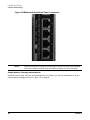
Figure 7-2
62
Ethernet Switch Blade Front Panel
Chapter 7
A Sample VLAN Topology
A Sample VLAN Topology
In the simplest terms, a VLAN is a user-defined set of these ports, grouped together such that they live in the
same subnet. A VLAN can be given an IP address that serves as an endpoint (or destination) for outside
traffic, or it may live anonymously within the Switch Blade and rely on established switch routing to send or
receive traffic on an anonymous VLAN.
Network Interfaces Partitions
The best way to think about partitioning the network interfaces is by modeling the intended use-cases. The
objective is to let the use-cases define the topology, and to let the topology define the VLANs you need to
create in your Ethernet Switch Blades. For this sample topology, there are three main use-cases:
•
Walk-up Configuration LAN: The Switch Blade OOB ports should be set up for walk-up configuration
purposes only; that is, to allow you to plug a laptop computer into the Switch Blade in order to gain access
to the Switch Blade configuration commands. The intent is that the OOB ports are protected by the
physical security imposed on the 14-Slot Shelf unit.
IMPORTANT These OOB LAN ports on the Switch Blades should never be plugged into an enterprise
network.
•
Management LAN: One base interface (the raw Ethernet connection zre12 that is exposed on the front
panel of the Switch Blade) is configured to support all the functions required for managing the 14-Slot
Shelf remotely. Management protocols such as SNMP, IPMI, and PXE send their traffic on the
management LAN. The management LAN is intended to be connected to the designated management
network within the enterprise. The remaining base interfaces (zre0 to 11, zre14 to 21) are configured into
a single VLAN in order to provide control-plane connectivity to all blades in the 14-Slot Shelf.
•
Payload LAN: The fabric interfaces (zre0 to 51 fabric) are configured for bearer or payload traffic - that
is, application traffic requiring intra- and inter-shelf networking.
Other use-cases center on the switch-to-switch traffic (between Ethernet Switch Blades), and on the traffic
from the Ethernet Switch Blades to the Shelf Managers (ShMMs). Each use-case defines another part of this
sample network topology:
•
Switch-to-Switch LAN: Creates a private network that enables the two Switch Blades to talk to each
another. This link is called the Inter-Switch Link (ISL), and accomplishes three goals:
— Traffic hitting one Switch Blade can see the network devices connected to the other Switch Blade.
— Each Switch Blade can see the active ShMM at all times.
— This LAN is also needed for High Availablility (HA) operation.
NOTE
•
This VLAN contains raw Ethernet connections zre22 and zre23; zre22 connects the
Switch Blade to the same-side ShMM, and zre23 is the Inter-Switch link (ISL) between
the two Switch Blades.
ShMM Cross-connect LAN:
Creates a private network on each Ethernet Switch Blade connecting to the opposite-side ShMM by
configuring the eth1 interface of each ShMM. The zre13 port allows you to talk from the Switch Blade to
the opposite-side ShMM. This subnet, in combination with the switch-to-switch LAN above, guarantees
that each Switch Blade can always talk directly to the active ShMM - even if one of the Ethernet Switch
Blades were to fail, and the active ShMM is on the opposite-side of the surviving Switch Blade.
Chapter 7
63
A Sample VLAN Topology
A Sample VLAN Topology
This topology also allows you to hide some functionality of the ShMM behind the Switch Blades. This
means that blades within the 14-Slot Shelf and devices outside of the 14-Slot Shelf are not allowed to
connect directly to the ShMMs. All ShMM management traffic (SNMP / IPMI) is routed through the
Switch Blades via one of these private LANs, and onto the externally-exposed management LAN. Not
connecting directly to the ShMM enhances the overall security of the 14-Slot Shelf.
IMPORTANT
The ShMM command set is powerful enough to bring down or reboot the entire shelf. By
exposing only the management traffic you want through the Switch Blades, you allow the
ShMM to do its job without opening a major security hole for the complete 14-Slot Shelf.
In this sample, you will create five separate VLANs on the Ethernet Switch Blades to build your network
topology. You will have a topology that looks like Figure 7-3, and includes the following VLANs:
Figure 7-3
Simplified Block Diagram of the Sample VLAN Topology
•
vlan1: Cross-connects each Ethernet Switch Blade to the opposite-side ShMM.
•
vlan2: Creates a Management LAN for the entire 14-Slot Shelf.
•
vlan3: Combines the remaining base interfaces (control plane) into a single VLAN.
•
vlan4: Creates a switch-to-switch LAN, and includes the same-side ShMM.
64
Chapter 7
A Sample VLAN Topology
A Sample VLAN Topology
•
vlan5: Combines the fabric interfaces (bearer plane) into a single VLAN.
The only connections to the outside enterprise are through VLAN2 (base management LAN), VLAN3 (base
control LAN), and VLAN5 (fabric payload LAN).
The management network takes up one base interface (zre12). The control network consumes the remaining
base interfaces (zre0 to 11, zre14 to 21) and the payload network consumes all fabric interfaces (zre0 to 51
fabric). The only network connecting outside of the 14-Slot Shelf that actually requires an assigned IP
address is the management network. The control and payload networks, while needing physical connectivity
to the outside, do not require assigned IP addresses because these VLANs just act as a switch, switching
traffic to and from the endpoints on these networks.
Building the Sample Topology in the 14-Slot Shelf
To build this network topology of five VLANs in the 14-Slot Shelf, you will start with the ShMM (because it
requires the lesser amount of configuration) and then move on to the Ethernet Switch Blade.
Shelf Manager Usage and Configuration
In order to configure a Shelf Manager (ShMM), you must first connect your terminal or laptop computer to
the respective ShMM serial port. The two ShMM serial ports (one RJ-45 connector for each ShMM) are
mounted on the Alarm Display Panel (Figure 7-4), which is located on the upper-left front of the 14-Slot Shelf.
Serial access (RS-232) is set to 8 data bits, 1 stop bit, no parity, and 9600 baud.
Figure 7-4
Identifying 2 RJ-45 Shelf Manager Serial Connectors on the Alarm
Display Panel
IMPORTANT You must use an RJ-45/DB-9 Adapter Cable (Part Number A6800-63006, see Figure 7-5 on
page 66) supplied with your HP bh5700 ATCA 14-Slot Blade Server in combination with a
Modem Eliminator Cable that has a DB-9 female connector on each end) in order to connect
your terminal or laptop computer to a ShMM serial port on the 14-Slot Shelf.
Chapter 7
65
A Sample VLAN Topology
A Sample VLAN Topology
Figure 7-5
RJ-45/DB-9 Console Adapter Cable
Shelf Manager Command Line Interface and Basic Commands
After connecting your terminal or laptop to a ShMM, login to the ShMM as root. The ShMM command line
interface prompt (clia) will appear on your terminal or laptop display. Use the ShMM command line interface
to enter the following basic ShMM commands and see how they work:
clia help This command gives you a list of all ShMM commands.
clia shmstatus This command tells you if this ShMM is the active ShMM, or the backup.
clia board -v This command tells information about the blade population in the shelf.
clia switchover This command causes the backup ShMM to become active, and forces the active ShMM to
reboot, and then go into backup mode.
clia boardreset 1 This command causes the blade in physical slot 1 to reboot. If there is no blade in slot 1,
the command has no effect.
If you want to learn more about specific ShMM commands, refer to the HP bh5700 ATCA 14-Slot Blade
Server, Shelf Manager User and Service Guide and the Shelf Manager External Interface User and Service
Guide.
Configuring eth0
In order to configure eth0 (the RMCP network adapter default IP address) on the ShMM, you must first
ensure that jumpers B141 to 144 on both ShMM carrier boards are installed in the back position (see
Figure 7-6 on page 67). This ensures that eth0 is ported to the 14-Slot Shelf backplane, and not to the ShMM
front panel. Complete the following steps to ensure these jumpers are installed as required:
Step 1. Remove the ShMM you are about to configure from the 14-Slot Shelf. See the HP bh5700 ATCA
14-Slot Blade Server, Maintenance Guide, Removal and Replacement Procedures document for
instructions on removing and reinstalling the ShMM.
CAUTION
Observe all ESD safety precautions while completing this procedure. Failure to
follow ESD safety precautions could result in damage to the 14-Slot Shelf and
equipment.
Step 2. With the ShMM removed, ensure that jumpers B141 to B144 on the ShMM carrier board are
installed in the back position (toward the rear of the carrier board), as shown in Figure 7-6 on
page 67.
66
Chapter 7
A Sample VLAN Topology
A Sample VLAN Topology
Figure 7-6Identifying Jumpers B141 to B144 Installed on ShMM Carrier Board
Jumpers B141, B142,
B143, and B144
Step 3. Reinstall the ShMM Carrier Board in the 14-Slot Shelf.
The default IP address for eth0 for the ShMM is either 10.0.0.52 (active ShMM) or 10.0.0.53 (backup
ShMM). Since you are hiding the ShMMs on their own private network such that they are only known to the
Switch Blade, you will move eth0 to the 192.168.0.x network.
To move eth0 to the 192.168.0.x network, complete the following steps:
Step 1. Enter the following ShMM commands on the active ShMM:
clia setlanconfig 1 3 192.168.0.2
This command sets the IP address of the active and backup ShMMs for eth0.
clia setlanconfig 1 6 255.255.255.0
This command sets the netmask of the active and backup ShMMs for eth0.
Chapter 7
67
A Sample VLAN Topology
A Sample VLAN Topology
clia setlanconfig 1 12 192.168.0.43
This command sets the gateway address of the active and backup ShMMs for eth0.
NOTE
In the sample network topology, the default gateway of the ShMM must be set to the
IP address of one of the Ethernet Switch Blades in the vlan4 subnet. Configuration
of vlan4 is covered in the Ethernet Switch Blade configuration section found later in
this document.
Step 2. To check your work, enter the following ShMM command:
clia fruinfo -v 20 1 | more
This command displays the contents of the persistent ShMM settings as held in the chassis
non-volatile FRU (field replaceable unit) memory. You will see the LAN configuration, as you have
entered it in the previous commands.
NOTE
Another way to check your work is to issue the following UNIX command:
ifconfig eth0
•
On the active ShMM, the IP address should be reported as: 192.168.0.2
•
On the backup ShMM, the IP address should be reported as: 192.168.0.3
Configuring eth1
Now that eth0 is configured, you need to set up eth1. Note that eth1 is not configured in the default ShMM
configuration, and must be set up so that each switch can talk directly to its opposite side ShMM. This is done
by adding one ifconfig command in the rc startup file /etc/rc.acb4.
Step 1. Add the following text to the /etc/rc.acb4 file prior to Step 4, highlighted as shown:
# Configure ShMM eth1 interface for cross-connecting to
# the opposite-side switch.
#
ifconfig eth1 192.168.2.2 netmask 255.255.255.0 up
########
# Step 4: Start up daemons
########
.
.
.
IMPORTANT Ensure this configuration change is added to each ShMM.
68
Chapter 7
A Sample VLAN Topology
A Sample VLAN Topology
NOTE
The IP address for eth1 is the same on both ShMMs. Each ShMM resides in a private
network that is created by the opposite side Ethernet Switch Blade.
Step 2. In the /etc/shelfman.conf file of both ShMMs, change the value of the following variables as
shown:
SWITCH_OVER_TIMEOUT_ON_BROKEN_LINK needs to be set to a value of 120 or above. This numeric
value is the number of seconds that will lapse between when eth0 on the ShMM is detected as down
and when the active ShMM performs a failover to the backup ShMM. The value should be at least
longer that it takes to reboot an Ethernet Switch Blade, otherwise rebooting a Switch Blade can
cause the ShMMs to failover. Enter your value as follows: SWITCHOVER_TIMEOUT_ON_BROKEN_LINK
= 120
RMCP_NET_ADAPTER2 needs to be set to a non-interface name, since you are controlling both network
interfaces of the ShMM directly. By default, RMCP_NET_ADAPTER2 is set to eth1, which, under
certain ShMM failure modes, causes the IP address of eth0 to be re-instantiated on eth1. In order to
prevent this behavior, which is incompatible with your sample network topology, change the value
to: RMCP_NET_ADAPTER2 = “noeth”
Step 3. After making the above configuration changes, reboot both ShMMs.
IMPORTANT These configuration changes will have to be repeated when any of the following occur:
•
A ShMM is replaced
•
The ShMM firmware is updated
•
The ShMM is reset to factory default settings
Configuring the Ethernet Switch Blade
To configure the base and fabric switch functions of an Ethernet Switch Blade, connect your terminal or
laptop computer to the base and fabric serial ports (one port at a time) of a Switch Blade. The Ethernet
Switch Blade serial ports (RJ-45 connectors) are mounted on the Ethernet Switch Blade front panel, as shown
in Figure 7-7 and Figure 7-8 on page 70.
Chapter 7
69
A Sample VLAN Topology
A Sample VLAN Topology
Figure 7-7
Ethernet Switch Blade Front Panel Base Serial Ports
Figure 7-8
Ethernet Switch Blade Front Panel Fabric Serial Ports
70
Chapter 7
A Sample VLAN Topology
A Sample VLAN Topology
IMPORTANT You must use an RJ-45/DB-9 Adapter Cable (supplied with your HP bh5700 ATCA 14-Slot
Blade Server) in combination with a modem eliminator cable (with a DB-9 female connector on
each end) in order to connect your terminal or laptop computer to a serial port on the 14-Slot
Shelf.
Serial access (RS-232) is set to 8 data bits, 1 stop bit, no parity, and 9600 baud. After connecting your terminal
or laptop to the base serial port, login as root.
Viewing the Default (or Current) Ethernet Switch Blade Configuration
To view the default (or current) Switch Blade base and fabric configuration, complete the following:
•
Ensure that your terminal or laptop computer is connected to either the base or fabric serial interface
RJ-45 connector, as desired. See Figure 7-7 on page 70 and Figure 7-8 on page 70.
•
Issue the following commands:
zconfig -a
This command shows the base or fabric interfaces that are currently configured into VLANs.
ifconfig
This command shows the network assignments for the defined base or fabric VLANs and OOB port.
Saving Your Changes When Rebooting the Switch Blade
The Ethernet Switch Blade always boots from a standard read-only OS image (OpenArchitect version 3.2.2).
Any changes you make are loaded from flash memory after the read-only OS image is booted. In order to
make user-level changes persistent, you must execute a zsync command prior to rebooting the Switch Blade.
NOTE
It is a good idea to make corresponding changes to both of the Ethernet Switch Blades at the
same time in order to keep your network topology consistent across the 14-Slot Shelf.
To save user-level changes and reboot the Switch Blade, issue the following commands:
zsync
reboot
Another option when rebooting the Switch Blade is to load the read-only OS, but not load any user-level
changes at boot time. To do this, issue the following command:
reboot -i
After performing a reboot -i, if you want to erase all user-level persistent changes, execute a zsync
command after the OS has rebooted from the reboot -i command.
Configuring SNMP
The Switch Blade automatically starts the snmpd daemon when it boots. However, you must make a change
to the snmpd.conf file on the Switch Blade, and you should also install a copy of the ShMM SNMP MIB onto
your system manager (that is, into the system where HP OpenView and other management applications that
manage the shelf are running).
On the Switch Blade, open the file /usr/share/snmp/snmpd.conf, and add the following SNMP proxy
directive, shown highlighted here:
Chapter 7
71
A Sample VLAN Topology
A Sample VLAN Topology
#
# net-snmp (or ucd-snmp) persistent data file.
#
syslocation unknown
syscontact unknown
sysservices 72
rocommunity public
rwcommunity private
#
# Proxy all requests intended for destination 16394 to the ShMM.
#
proxy -v1 -cpublic 192.168.0.2 enterprises.16394
#
# SMUX peer support (gated)
#
smuxpeer .1.3.6.1.4.1.4.3.1.4 secret
.
.
.
To save this change on the Switch Blade, enter the command:
zsync
In order to allow your system manager to translate SNMP queries (for example, snmpwalk) made against the
ShMM, you must place a copy of the ShMM’s MIB onto your system manager. The MIB is used by the system
manager to translate numerical information about the status and variables contained on the ShMMs.
The ShMM SNMP MIB is avaialable for download at this web site:
http://www.a-tca.com/dev_atca_new/download.asp?source=&file=pps.zip
Unzip the downloaded file, and then rename the MIB file to: PPS-SENTRY-MIB.txt. Copy this file to the
location on your system manager where your MIBs are kept. Optionally, you may put a copy of the ShMM
MIB onto your Switch Blade as: /usr/share/snmp/mibs/PPS-SENTRY-MIB.txt.
NOTE
The MIBs for the Switch Blades are kept under the directory: /usr/share/snmp/mibs. You
may also want to consider copying some of these Switch Blade MIBs to the designated system
manager.
Configuring eth0 Out-of-Band Port (The Walk-up Configuration Port)
The Out-of-Band Ethernet port is located below the serial access port on the Ethernet Switch Blade front
panel, and is labeled as OOB. See Figure 7-7 on page 70 and Figure 7-8 on page 70.
72
Chapter 7
A Sample VLAN Topology
A Sample VLAN Topology
This is the OOB eth0 port on the Switch Blade, and you want to use it as a walk-up configuration port. You (or
an administrator) are able to walk up to the ATCA 14-Slot Shelf with a laptop computer, plug into this port,
get an assigned IP address, and then use telnet to the Switch Blade to perform normal Switch Blade
configuration tasks. Using the dhcpd daemon provided on the Switch Blade, you can set up eth0 to be the
configuration port.
The eth0 configuration must be persistent, so that the eth0 port will be configured properly at boot time. To do
this, complete the following steps to create a dhcpd config file and an rc script that are used at boot time:
Step 1. Use the serial access port to log into the Switch Blade, then add the following dhcpd.eth0.conf
configuration file to the /etc directory:
# /etc/dhcpd.eth0.conf
#
# Hardwired to eth0 for dhcpd config at startup.
option domain-name "dhcpdefault.net";
option subnet-mask 255.255.255.0;
default-lease-time 2400;
max-lease-time 7200;
subnet 192.168.1.0 netmask 255.255.255.0 {
range 192.168.1.2 192.168.1.20;
option broadcast-address 192.168.1.255;
}
Step 2. Add the following S00dhcpd.eth0 rc script to the /etc/rcZ.d directory:
#!/bin/sh
#
#
#
#
#
#
/etc/rcZ.d/S00dhcpd.eth0
RC script to start/stop the dhcpd daemon on the eth0
interface. This allows eth0 to be used as a walk-up
config port.
#
# Create a variable that is the location of the process ID
# for the dhcpd daemon.
#
DHCPPID=/var/run/dhcpd.eth0
#
# Use the saved process ID as a handle to kill the daemon.
#
if [ "$1" = stop ]; then
[ -f "$DHCPPID" ] && kill `cat $DHCPPID`
rm -f $DHCPPID
ifconfig eth0 down
exit 0
fi
Chapter 7
73
A Sample VLAN Topology
A Sample VLAN Topology
#
# If you get to here, and you are not starting the daemon,
# display usage info, and exit.
#
[ "$1" != start ] && echo "usage: `basename $0` start | stop" && exit 0
#####################################################################
#
# Bring up the OOB port and dedicated DHCP server.
# Save the daemon process ID for killing the process later.
ifconfig eth0 192.168.1.1 netmask $NETMASK up
dhcpd -cf /etc/dhcpd.eth0.conf -pf $DHCPPID eth0#
Step 3. Issue the following command to make your changes persistent:
zsync
Step 4. Enter the following commands to start up the Switch Blade dhcpd daemon:
chmod 755 /etc/rcZ.d/S00dhcpd.eth0
/etc/rcZ.d/S00dhcpd.eth0 start
Step 5. Issue the following commands to verify that the dhcpd daemon is running:
ps -efw | grep dhcpd
The Switch Blade should return the following message:
root 163 1 0 Mar03 ? 00:00:11 dhcpd -cf /etc/dhcpd.eth0.conf -pf
/var/run/dhcpd.eth0 eth0
Step 6. Now that the daemon is running, try connecting an Ethernet cable from a laptop computer to the
OOB (eth0) port on the Switch Blade front panel. See Figure 7-7 on page 70 and Figure 7-8 on
page 70.
Step 7. Open a telnet session on your Linux laptop, and enter the command:
ifup eth0
Step 8. Enter the ifconfig command on your laptop to verify that the laptop’s eth0 received an IP address
from the Switch Blade, as follows:
ifconfig eth0
eth0
Link encap:Ethernet HWaddr 00:11:65:09:EF:FC
inet addr:192.168.1.2 Bcast:192.168.1.255 Mask:255.255.255.0
UP BROADCAST MULTICAST MTU:1500 Metric:1
RX packets:0 errors:0 dropped:0 overruns:0 frame:0
TX packets:0 errors:0 dropped:0 overruns:0 carrier:0
collisions:0 txqueuelen:100
RX bytes:0 (0.0 b) TX bytes:0 (0.0 b)
Base address:0x8400
74
Chapter 7
A Sample VLAN Topology
A Sample VLAN Topology
Step 9. Now that the laptop has an IP address, telnet to the Switch Blade to make all further configuration
changes by entering the following:
telnet 192.168.1.1
The Out-of-band port is now configured as your walk-up configuration port.
IMPORTANT Make the same set of changes to the redundant, failover Ethernet Switch Blade at
this time in order to maintain High Availability integrity for the 14-Slot Shelf.
Configuring the Opposite-Side Shelf Manager (zre13 base)
You are now ready to start configuring the base interfaces on the Ethernet Switch Blade. The first one that
you want to configure is vlan1, which is the network that connects your Switch Blade to the opposite side
ShMM. To configure the opposite side ShMM, complete the following steps:
Step 1. Tear down all base interfaces by issuing the following command:
zconfig -t
Step 2. To build vlan1, and to make sure it is recreated when you reboot the Switch Blade, add the
following S21cross-shmm rc script to the /etc/rcZ.d directory:
#!/bin/sh
#
# /etc/rcZ.d/S21cross-shmm
#
# rc script to build vlan1 that connects the Switch Blade
# to the opposite-side ShMM.
#
set -u
case "$1" in
start)
#
Build vlan1 that connects the Switch Blade to the
# cross-connected ShMM.
#
zconfig zhp0: vlan1=zre13
# ShMM eth1 cross-connect
zconfig zre13=untag1
# Assign an IP address to zhp0/vlan1:
# The "other side" ShMM eth1 is always 192.168.2.2.
#
ifconfig zhp0 192.168.2.1 netmask 255.255.255.0 up
;;
stop)
Chapter 7
75
A Sample VLAN Topology
A Sample VLAN Topology
# Tear down vlan1 that connects the Switch Blade to the
# cross-connected ShMM.
#
ifconfig zhp0 down
zconfig zhp0:teardown
;;
*)
echo "Usage: $0 { start | stop }"
exit 1
esac
exit 0
Step 3. Issue the zsync command to make the rc script persistent:
zsync
Step 4. Enter the following commands in order to start up zhp0/vlan1:
chmod 755 /etc/rcZ.d/S21cross-shmm
/etc/rcZ.d/S21cross-shmm start
Step 5. Determine if zhp0/vlan1 is properly configured by using the following commands:
zconfig -a
zhp0: vlan1 = zre13
zre13 = untag1
ifconfig zhp0
zhp0
Link encap:Ethernet HWaddr 00:11:65:09:EC:18
inet addr:192.168.2.1 Bcast:192.168.2.255 Mask:255.255.255.0
UP BROADCAST RUNNING MULTICAST MTU:1500 Metric:1
RX packets:204 errors:0 dropped:0 overruns:0 frame:0
TX packets:302 errors:0 dropped:0 overruns:0 carrier:0
collisions:0 txqueuelen:100
RX bytes:15327 (14.9 Kb) TX bytes:20677 (20.1 Kb)
Base address:0xc000
NOTE
Make the same set of changes to the redundant, failover Ethernet Switch Blade at
this time in order to maintain High Availability integrity for the 14-Slot Shelf.
Configuring the Management LAN (zre12 base)
You are now ready to configure the management LAN, which is denoted as vlan2 in your sample network
topology. This VLAN (vlan2) consists of a single base interface (zre12). Note that the zre12 port is accessible
at an RJ-45 connector on the Ethernet Switch Blade front panel, as shown in Figure 7-9.
76
Chapter 7
A Sample VLAN Topology
A Sample VLAN Topology
Figure 7-9
The zre12 Base Interface, Ethernet Switch Blade Front Panel
To build the Management LAN, complete the following steps:
Step 1. To build vlan2 and ensure that it is recreated when you reboot the Switch Blade, you must add an
rc script. Add the following S22mgmt rc script to the /etc/rcZ.d directory:
NOTE
In the following script, you will want to provide an IP address for zhp1/vlan2 that is
compatible with your management network. The IP address shown in the following
script is just an example.
#!/bin/sh
#
# /etc/rcZ.d/S22mgmt
#
# rc script to build the management VLAN for
# the ATCA shelf.
#
Chapter 7
77
A Sample VLAN Topology
A Sample VLAN Topology
set -u
case "$1" in
start)
# Build vlan2 that contains zre12 as the only
# configured port.
#
zconfig zhp1: vlan2=zre12
# zre12 egress is front-panel
zconfig zre12=untag2
# Assign an IP address to zhp1/vlan2:
#
ifconfig zhp1 10.35.50.41 netmask 255.0.0.0 up
;;
stop)
# Tear down vlan2 that contains zre12.
#
ifconfig zhp1 down
zconfig zhp1:teardown
;;
*)
echo "Usage: $0 { start | stop }"
exit 1
esac
exit 0
Step 2. Enter the zsync command to make the rc script persistent:
zsync
Step 3. Enter the following commands in order to start up zhp1/vlan2:
chmod 755 /etc/rcZ.d/S22mgmt
/etc/rcZ.d/S22mgmt start
Step 4. Use the following commands to verify that zhp1/vlan2 is properly configured:
zconfig -a
zhp0:
zhp1:
zre13
zre12
vlan1 = zre13
vlan2 = zre12
= untag1
= untag2
ifconfig zhp1
zhp1
78
Link encap:Ethernet
HWaddr 00:11:65:09:EC:19
Chapter 7
A Sample VLAN Topology
A Sample VLAN Topology
inet addr:10.35.50.41 Bcast:10.255.255.255 Mask:255.0.0.0
UP BROADCAST RUNNING MULTICAST MTU:1500 Metric:1
RX packets:1443377 errors:0 dropped:0 overruns:0 frame:0
TX packets:42 errors:0 dropped:0 overruns:0 carrier:0
collisions:0 txqueuelen:100
RX bytes:123946159 (118.2 Mb) TX bytes:1982 (1.9 Kb)
Base address:0xc000
Two VLANs have now been defined; one for the cross-connect to the opposite-side ShMM, and
another for the management LAN.
NOTE
To enable vlan2 to pass traffic to your management network, you must run a
network cable from the front panel of the Switch Blade (RJ-45 connector labeled 12)
to a network connector in your management network.
NOTE
Make the same set of changes to the redundant, failover Ethernet Switch Blade at
this time in order to maintain High Availability integrity for the 14-Slot Shelf.
Configuring the Control LAN and Remaining Base Interfaces
You are now ready to configure the remaining Ethernet Switch Blade base interfaces, which will become
vlan3. Note that vlan3 includes zre0 to zre11, and zre14 to zre21 on the Ethernet Switch Blade front panel.
The function of vlan3 is to serve as the Control LAN.
You do not need to assign an IP address to this VLAN, because the intent is that this VLAN merely passes
traffic through to endpoints defined elsewhere in the14-Slot Shelf. Any control plane traffic to the 14-Slot
Shelf will come in via vlan3, which (acting as a switch) will send the traffic to the appropriate blade in the
14-Slot Shelf.
IMPORTANT When configuring the base interfaces on the HP bc2100 ATCA Server Blades in this topology,
the Server Blade IP address must reside within the control network space to properly connect
to the 14-Slot Shelf and to the outside enterprise.
To build vlan3, complete the following steps:
Step 1. Add the following S23base rc script to the /etc/rcZ.d directory to ensure that vlan3 is recreated
when you reboot the Ethernet Switch Blade:
#!/bin/sh
#
# /etc/rcZ.d/S23base
#
# rc script to build the base interface VLAN for
# the ATCA shelf.
#
set -u
Chapter 7
79
A Sample VLAN Topology
A Sample VLAN Topology
case "$1" in
start)
# Build vlan3 that contains zre0..11,zrezre14..21.
#
zconfig zhp2: vlan3=zre0..11,zre14..21
zconfig zre0..11,zre14..21=untag3
# Do not assign an IP address to this zhp2/vlan3.
# Just set the state of zhp2/vlan3 to up.
#
ifconfig zhp2 up
;;
stop)
# Tear down vlan3 that contains zre0..11,zre14..21.
#
ifconfig zhp2 down
zconfig zhp2:teardown
;;
*)
echo "Usage: $0 { start | stop }"
exit 1
esac
exit 0
Step 2. Enter the following command line to move the default script out of the way. This will ensure that
the default script does not execute on the Switch Blade that configures the base interfaces:
mv /etc/rcZ.d/S50layer2 /etc/rcZ.d/off.S50layer2
Step 3. Enter the zsync command to make the rc script persistent:
zsync
Step 4. Enter the following commands to start up zhp2/vlan3:
chmod 755 /etc/rcZ.d/S23base
/etc/rcZ.d/S23base start
Step 5. Use the following commands to ensure that zhp2/vlan3 is properly configured:
zconfig -a
zhp0: vlan1 = zre13
zhp1: vlan2 = zre12
zhp2: vlan3 = zre0..11, zre14..21
80
Chapter 7
A Sample VLAN Topology
A Sample VLAN Topology
zre13 = untag1
zre12 = untag2
zre0..11, zre14..21 = untag3
ifconfig zhp2
zhp2
Link encap:Ethernet
HWaddr 00:11:65:09:EC:1A
UP BROADCAST RUNNING MULTICAST
MTU:1500
Metric:1
RX packets:3582 errors:0 dropped:0 overruns:0 frame:0
TX packets:0 errors:0 dropped:0 overruns:0 carrier:0
collisions:0 txqueuelen:100
RX bytes:549764 (536.8 Kb)
TX bytes:0 (0.0 b)
Base address:0xc000
Three of the VLANs in the sample topology have now been defined; one for the cross connect to the
opposite side ShMM, a second for the management LAN external connection, and a third for the
remaining base interfaces in the 14-Slot Shelf.
IMPORTANT Enable vlan3 to pass traffic to the control network. You must run a network cable
from the front panel of the Switch Blade (choose one of the RJ-45 connectors labeled
14 or 15) to a network connector in your control network.
NOTE
Make the same set of changes to the redundant, failover Ethernet Switch Blade at
this time in order to maintain High Availability integrity for the 14-Slot Shelf.
Configuring the Inter-Switch Link and Same Side Shelf Manager (zre22 to 23 base)
You are now ready to configure vlan4 of our sample topology, which is the Inter-Switch Link (ISL) and the
connection to the same side ShMM. This VLAN consists of a 2 base interfaces (zre22 which is the same side
ShMM and zre23 which is the ISL).
In the following script, provide an IP address for zhp3/vlan4 that is compatible with the IP
address you assigned to eth0 on your ShMMs. The IP address shown in the script is only an
example.
NOTE
To build vlan4, complete the following steps:
Step 1. Add the following S24isl rc script to the /etc/rcZ.d directory to ensure that vlan3 is recreated
when you reboot the Ethernet Switch Blade:
#!/bin/sh
#
Chapter 7
81
A Sample VLAN Topology
A Sample VLAN Topology
# /etc/rcZ.d/S24isl
#
# rc script to build the inter-switch link (ISL) and
# connection to the same-side ShMM for the ATCA shelf.
#
set -u
case "$1" in
start)
# Build vlan4 that contains zre22..23.
#
zconfig zhp3: vlan4=zre22..23
zconfig zre22..23=untag4
# Assign an IP address to zhp3/vlan4:
#
ifconfig zhp3 192.168.0.43 netmask 255.255.255.0 up
;;
stop)
# Tear down vlan4 that contains zre22..23.
#
ifconfig zhp3 down
zconfig zhp3:teardown
;;
*)
echo "Usage: $0 { start | stop }"
exit 1
esac
exit 0
Step 2. Enter the zsync command to make the rc script persistent:
zsync
Step 3. Enter the following commands to start up zhp3/vlan4:
chmod 755 /etc/rcZ.d/S24isl start
/etc/rcZ.d/S24isl start
Step 4. Enter the following command to verify that zhp3/vlan4 is properly configured:
zconfig -a
zhp0: vlan1 = zre13
zhp1: vlan2 = zre12
zhp2: vlan3 = zre0..11, zre14..21
82
Chapter 7
A Sample VLAN Topology
A Sample VLAN Topology
zhp3: vlan4 = zre22..22
zre13 = untag1
zre12 = untag2
zre0..11, zre14..21 = untag3
zre22..23 = untag4
ifconfig zhp3
zhp3
Link encap:Ethernet HWaddr 00:11:65:09:EC:1B
inet addr:192.168.0.43 Bcast:192.168.0.255 Mask:255.255.255.0
UP BROADCAST RUNNING MULTICAST MTU:1500 Metric:1
RX packets:2228912 errors:0 dropped:0 overruns:0 frame:0
TX packets:1488770 errors:0 dropped:0 overruns:0 carrier:0
collisions:0 txqueuelen:100
RX bytes:156761552 (149.4 Mb) TX bytes:108022452 (103.0 Mb)
Base address:0xc000
Four VLANs have now been defined in this sample topology: one for the cross-connect to the
opposite-side ShMM, a second for the management LAN external connection, a third for the
remaining base interfaces in the 14-Slot Shelf (representing the control network), and a fourth for
the ISL and connection to the same-side ShMM.
NOTE
Make the same set of changes to the redundant, failover Ethernet Switch Blade at
this time in order to maintain High Availability integrity for the 14-Slot Shelf.
Configuring the Switch Blade – Hiding the ShMM and Exposing RMCP and SNMP-TRAP
Now you need to set up some iptable rules that allow us to effectively hide the ShMMs in their own private
network, while still allowing RMCP and IPMI traffic to flow to and from the 14-Slot Shelf over the established
management network. The reason for doing this is to establish better security for the 14-Slot Shelf.
To enhance security, blades or outside devices should not connect directly to the ShMMs. Instead, you want to
expose the interesting management data from the ShMMs through the RMCP protocol. This network traffic
originates from the management network, passes through the Switch Blades, and onto the ShMM’s private
network. Using the sample network topology, the only devices that can directly connect to the ShMM’s console
are serial devices that are in the same physical location as the ShMMs and the Ethernet Switch Blades.
To hide the ShMM and expose the RMCP and SNMP-TRAP, complete the following steps:
Step 1. To gain access to the ShMM using the RMCP protocol and to allow SNMP traffic to flow to agents
running on the ShMMs and other blades, add two lines to the /etc/services configuration file on
each Switch Blade.
Using the base serial port, or the configuration port you set up previously, add the following lines to
the /etc/services file on each Switch Blade:
rmcp623/udp# To allow RMCP traffic to ShMMs.
agentx705/tcp# To allow traffic to off-switch sub-agents.
Step 2. Enter the following command to load the iptables driver into kernel memory:
insmod /lib/modules/2.4.2/kernel/net/ipv4/netfilter/iptable_nat.o
Chapter 7
83
A Sample VLAN Topology
A Sample VLAN Topology
Step 3. Enter the following command to verify that the iptables driver loaded properly:
lsmod
Module
iptable_nat
bridge
if_zxe
zfm_c
Size
15968
37040
5586552
271160
Used by
0 (unused)
0 (unused)
5
0
Step 4. To set up the iptable rules and ensure that they are reestablished when you reboot the Ethernet
Switch Blade, you must add an rc script. Add the following S25iptables rc script to the
/etc/rcZ.d directory:
#!/bin/sh
#
# /etc/rcZ.d/S25iptables
#
# rc script to build iptables that hide the ShMMs from direct
# access by blades or outside devices, but allows rmcp traffic in
# and snmp-trap traffic out.
#
set -u
case "$1" in
start)
#
# Load iptables driver into kernel memory
#
insmod /lib/modules/2.4.2/kernel/net/ipv4/netfilter/iptable_nat.o
#
# Set the IP addresses of the management LAN (vlan2), the
# ISL LAN (vlan4), and the SHMM (also on vlan4).
#
MGMT_IP=10.35.50.41
ISL_IP=192.168.0.43
84
Chapter 7
A Sample VLAN Topology
A Sample VLAN Topology
SHMM_IP=192.168.0.2
#
# Choose a mark your pre-routing DNAT rule.
#
MARK_DNAT=1
#
# Initialize iptables, and flush any existing rules.
#
iptables -P INPUT
ACCEPT
iptables –P OUTPUT
ACCEPT
iptables -P FORWARD DROP
iptables -F; iptables -F -t nat; iptables -F -t mangle
iptables -X
#
# Set up some NAT rules to allow rmcp traffic to flow to the
# SHMM, and to allow snmp-trap traffic, initiated from the SHMM,
# to flow to the designated system manager. Restrict all other
# outside traffic from directly talking to the SHMM.
#
#
# Mark incoming rmcp packets destined for the SHMM
#
iptables -t mangle -A PREROUTING -p udp -d $MGMT_IP \
-m multiport --dports rmcp -j MARK --set-mark ${MARK_DNAT}
#
# NAT rmcp packets to the SHMM.
#
Chapter 7
85
A Sample VLAN Topology
A Sample VLAN Topology
iptables -t nat -A PREROUTING -p udp -d $MGMT_IP --dport \
rmcp -j DNAT --to-destination $SHMM_IP
#
# Change source ip of rcmp packet, so that SHMM can respond to
# the correct left or right Switch Blade.
#
iptables -t nat -A POSTROUTING -p udp -o zhp3 \
-mmark --mark ${MARK_DNAT}/${MARK_DNAT} -j SNAT \
--to-source $ISL_IP:10000-10999
#
# Allow snmp-trap traffic, initiated from the SHMM, to go to the
# designated system manager.
#
iptables -t nat -A POSTROUTING -p udp -s $SHMM_IP \
-o zhp1 --dport 162 -j SNAT --to-source $MGMT_IP:10000-10999
#
# Allow the following traffic to enter the Switch Blade.
#
iptables -A INPUT
-j ACCEPT
-m state \
--state ESTABLISHED,RELATED
86
iptables -A INPUT
-j ACCEPT
-i lo
iptables -A INPUT
-j ACCEPT
-i zhp3
iptables -A INPUT
-j ACCEPT
-p tcp --dport ftp
iptables -A INPUT
-j ACCEPT
-p udp --dport tftp
iptables -A INPUT
-j ACCEPT
-p tcp --dport http
iptables -A INPUT
-j ACCEPT
-p tcp --dport telnet
iptables -A INPUT
-j ACCEPT
-p udp --dport snmp
iptables -A INPUT
-j ACCEPT
-p udp --dport snmp-trap
iptables -A INPUT
-j ACCEPT
-p icmp --icmp-type echo-request
Chapter 7
A Sample VLAN Topology
A Sample VLAN Topology
#
# Everything else coming into the Switch Blade, reject.
#
iptables -A INPUT
-j REJECT
#
# Allow the following traffic to be forwarded from the Switch Blade.
#
iptables -A FORWARD -j ACCEPT
-m state \
--state ESTABLISHED,RELATED
iptables -A FORWARD -j ACCEPT
\
-mmark --mark ${MARK_DNAT}/${MARK_DNAT}
iptables -A FORWARD -j ACCEPT
-i lo
#
# Everything else that could be forwarded, reject.
#
iptables -A FORWARD -j REJECT
;;
stop)
#
# Flush iptables
#
iptables -F; iptables -F -t nat; iptables -F -t mangle
iptables -X
;;
*)
Chapter 7
87
A Sample VLAN Topology
A Sample VLAN Topology
echo "Usage: $0 { start | stop }"
exit 1
esac
exit 0
NOTE
The above script is one method of hiding the ShMM from the broader enterprise
network. It is not the only method of achieving this objective, and network
administrators may need to modify the script according to their particular network
requirements.
NOTE
SNMP traffic targeted for the ShMM will come in through the Switch Blade, and will
be redirected to the ShMM by the proxy directive that you added earlier to the
Switch Blade configuration file /usr/share/snmp/snmpd.conf.
Step 5. Enter the following command to make the rc script persistent:
zsync
Step 6. Enter the following command to start up the iptable rules:
chmod 755 /etc/rcZ.d/S25iptables
/etc/rcZ.d/S25iptables start
Step 7. Enter the following to see if the iptable rules are established:
iptables -nvL
Chain INPUT (policy ACCEPT
pkts bytes target
prot
76 6125 ACCEPT
all
state RELATED,ESTABLISHED
0
0 ACCEPT
all
0
0 ACCEPT
all
2
120 ACCEPT
tcp
tcp dpt:21
0
0 ACCEPT
udp
udp dpt:69
0
0 ACCEPT
tcp
tcp dpt:80
0
0 ACCEPT
tcp
tcp dpt:22
0
0 ACCEPT
tcp
tcp dpt:23
0
0 ACCEPT
udp
udp dpt:161
0
0 ACCEPT
udp
88
1 packets, 328 bytes)
opt in
out
source
-- *
*
0.0.0.0/0
destination
0.0.0.0/0
----
lo
zhp3
*
*
*
*
0.0.0.0/0
0.0.0.0/0
0.0.0.0/0
0.0.0.0/0
0.0.0.0/0
0.0.0.0/0
--
*
*
0.0.0.0/0
0.0.0.0/0
--
*
*
0.0.0.0/0
0.0.0.0/0
--
*
*
0.0.0.0/0
0.0.0.0/0
--
*
*
0.0.0.0/0
0.0.0.0/0
--
*
*
0.0.0.0/0
0.0.0.0/0
--
*
*
0.0.0.0/0
0.0.0.0/0
Chapter 7
A Sample VLAN Topology
A Sample VLAN Topology
udp dpt:162
0
0 ACCEPT
icmp -- *
icmp type 8
1442 334K REJECT
all -- *
reject-with icmp-port-unreachable
Chain FORWARD (policy DROP 0 packets,
pkts bytes target
prot opt in
386 21728 ACCEPT
all -- *
state RELATED,ESTABLISHED
2
102 ACCEPT
all -- *
MARK match 0x1/0x1
0
0 ACCEPT
all -- lo
0
0 REJECT
all -- *
reject-with icmp-port-unreachable
*
0.0.0.0/0
0.0.0.0/0
*
0.0.0.0/0
0.0.0.0/0
0 bytes)
out
source
*
0.0.0.0/0
destination
0.0.0.0/0
*
0.0.0.0/0
0.0.0.0/0
*
*
0.0.0.0/0
0.0.0.0/0
0.0.0.0/0
0.0.0.0/0
Chain OUTPUT (policy ACCEPT 66 packets, 10224 bytes)
pkts bytes target
NOTE
prot opt in
out
source
destination
Make the same set of changes to the redundant, failover Ethernet Switch Blade at
this time in order to maintain High Availability integrity for the 14-Slot Shelf.
Configuring the Fabric Interfaces (zre0 to 51 fabric)
Configure the fabric interfaces on the Ethernet Switch Blade, which will then become vlan5. The sample
topology vlan5 includes fabric ports zre0 through zre51. There is no need to assign an IP address to this
VLAN as it merely passes traffic through to endpoints defined elsewhere in the 14-Slot Shelf. Any fabric
plane traffic to the 14-Slot Shelf will come in through vlan5, which (acting as a switch), will send the traffic to
the appropriate blade in the 14-Slot Shelf.
IMPORTANT When configuring the fabric interfaces on the HP bc2100 ATCA Server Blades, it is important
to note that (in this topology) the Server Blade IP address must to reside within the fabric
network space to ensure proper connectivity to the 14-Slot Shelf and to the outside enterprise.
To build vlan5, complete the following steps:
Step 1. Connect your laptop computer or terminal RS-232 port to the lower (fabric) serial port on the
Switch Blade front panel.
Step 2. Issue the following command to ensure that all fabric interfaces are torn down:
zconfig -t
Step 3. Add the following S50fabric rc script to the /etc/rcZ.d directory to ensure that the fabric
interfaces are recreated when you reboot the Ethernet Switch Blade:
#!/bin/sh
#
Chapter 7
89
A Sample VLAN Topology
A Sample VLAN Topology
# /etc/rcZ.d/S50fabric
#
# rc script to build the fabric interface VLAN for
# the ATCA shelf.
#
set -u
case "$1" in
start)
# Build vlan5 that contains zre0..51 fabric.
#
zconfig zhp4: vlan5=zre0..51
zconfig zre0..51=untag5
# Do not assign an IP address to this zhp4/vlan5.
# Just set the state of zhp4 to up.
#
ifconfig zhp4 up
;;
stop)
# Tear down vlan5 that contains zre0..51.
#
ifconfig zhp4 down
zconfig zhp4:teardown
;;
*)
echo "Usage: $0 { start | stop }"
exit 1
esac
exit 0
IMPORTANT The zre51 port is the Inter-Switch Link (ISL) for the fabric-side of the switch. If you
plan to connect the fabric portion of each switch into the same external network, do
not include zre51 in this VLAN configuration, as it will create a network loop and
likely bring down the external network. In this case, create a separate VLAN for
zre51 so that the ISL is isolated from the external network.
Step 4. Enter the following command line to move the default script out of the way. This will ensure that
the default script does not execute on the Switch Blade that configures the base interfaces:
mv /etc/rcZ.d/S50layer2 /etc/rcZ.d/off.S50layer2
Step 5. Enter the zsync command to make the rc script persistent:
zsync
90
Chapter 7
A Sample VLAN Topology
A Sample VLAN Topology
Step 6. Enter the following commands to start up zhp4/vlan5:
chmod 755 /etc/rcZ.d/S50fabric
/etc/rcZ.d/S50fabric start
Step 7. Enter the following commands to see if zhp4/vlan5 is properly configured:
zconfig -a
zhp4: vlan5 = zre0..51
zre0..51 = untag5
ifconfig zhp4
zhp4
Link encap:Ethernet
HWaddr 00:11:65:0C:F0:38
UP BROADCAST RUNNING MULTICAST
MTU:1500
Metric:1
RX packets:0 errors:0 dropped:0 overruns:0 frame:0
TX packets:0 errors:0 dropped:0 overruns:0 carrier:0
collisions:0 txqueuelen:100
RX bytes:0 (0.0 b)
TX bytes:0 (0.0 b)
Base address:0x5000
Now you have defined one VLAN (vlan5) that covers all fabric interfaces from zre0 to zre51on the
fabric side of the Switch Blade. Network administrators may want to configure the fabric side of the
Switch Blade differently, depending on their network requirements.
IMPORTANT The zre51 fabric port is the Inter-Switch Link (ISL) between the two Switch Blades.
If you do not want fabric traffic to pass from one Switch Blade to the other, do not
configure zre51.
NOTE
Chapter 7
For vlan5 to pass traffic to your fabric/payload network, you must run a network
cable from the Ethernet Switch Blade front panel (choose one of the RJ-45 connectors
labeled 20, 21, 22, or 23) to a network connector in your fabric/payload network. The
Switch Blade front panel fabric connectors are shown in Figure 7-10.
91
A Sample VLAN Topology
A Sample VLAN Topology
Figure 7-10Ethernet Switch Blade Fabric Connectors
NOTE
Make the same set of changes to the redundant, failover Ethernet Switch Blade at
this time in order to maintain High Availability integrity for the 14-Slot Shelf.
Sample Network Topology Implementation
Now that vlan1 through vlan5 are configured (above in this chapter), you have an implementation of your
sample network topology as shown in Figure 7-11 on page 93.
92
Chapter 7
A Sample VLAN Topology
A Sample VLAN Topology
Figure 7-11
Configured Sample Network Topology
Ethernet Switch Blade Port and IPMB Mappings
Figure 7-12 on page 94 provides an Ethernet Switch Blade Port and IPMB map to help you understand how
the base and fabric zre and IPMB addresses are mapped inside the HP bh5700 ATCA 14-Slot Blade Server.
Chapter 7
93
A Sample VLAN Topology
A Sample VLAN Topology
Figure 7-12
Port IPMB Mapping
Base face = 12 xx 14 15
Base rear = 16 17 18 19
Fabric face = 20 21 22 23 Fabric rear = 44 45 46 47
10Gb = 48 49 50
Configuring the HP bc2100 ATCA Server Blade Ethernet Interface Connectors
To connect your HP bc2100 ATCA Server Blades into the sample network topology (created earlier in this
chapter), you must configure at least some of the Ethernet interfaces included in the Server Blade. There are
six Ethernet external interface connectors on each Server Blade; eth0 through eth5. Table 7-1 provides a map
of the Server Blade.
Table 7-1
14-Slot Shelf Server Blade External Ethernet Connections
Server Blade Interface
Switch Blade
Connection
Base or Fabric
eth0
Left Switch Blade
Base
eth1
Right Switch Blade
Base
eth2
Left Switch Blade
Fabric
eth3
Right Switch Blade
Fabric
eth4
Left Switch Blade
Fabric
eth5
Right Switch Blade
Fabric
94
Chapter 7
A Sample VLAN Topology
A Sample VLAN Topology
IMPORTANT When setting up the eth0 through eth5 network interfaces on your Server Blades, remember
that any assigned IP address on these interfaces must reside within the base or fabric network
domains that you have already established for the Switch Blades.
NOTE
The external Ethernet interface mapping described in Table 7-1 on page 94 may vary,
depending on how your Linux kernel is configured and in what order the kernel detects the
physical network interfaces present on the Server Blade. Table 7-1 represents the mapping as
seen by the Debian (2.6 Kernel) Linux OS.
Serial access to the HP bc2100 ATCA Server Blade is provided through an RJ-45 connector located below the
four LAN ports (and just above the two USB connectors) on the Server Blade front panel. Serial access
(RS-232) is set to 8 data bits, 1 stop bit, no parity, and 9600 baud.
NOTE
You must use an RJ-45/DB-9 adapter cable (supplied with your HP bh5700 ATCA 14-Slot Blade
Server) in combination with a modem eliminator cable (with a DB-9 female connector on each
end) in order to connect your terminal or laptop computer to a serial port on the 14-Slot Shelf.
The Server Blade BIOS controls the activation of the four LAN fabric ports on the Server Blade front panel. If
the four LAN fabric ports are not active on the front panel, then they connect into the fabric domain of the
Switch Blades through the 14-Slot Shelf blade cage backplane.
NOTE
There is no designated out-of-band (OOB) LAN port for the Server Blade, as there is for the
Ethernet Switch Blades and the ShMMs.
Configuring the 14-Slot Blade Server for High Availability
High availability (HA) is a feature implemented within the Ethernet Switch Blades, and taken advantage of
the HP bc2100 ATCA Server Blades. This feature is also more formally known as Surviving Partner.
The Ethernet Switch Blades High Availability is implemented in the Ethernet Switch Blade using the
Inter-Switch Link (ISL / vlan4) that connects the two Switch Blades. In addition to the ISL, the Switch Blade
also employs the Virtual Router Redundancy Protocol, also known as vrrp. The vrrp protocol is implemented
as a daemon (vrrpd) that runs whenever the surviving partner software is enabled.
NOTE
The vrrpd daemon is an open source (GPL) project. You can download this code from the
following URL: https://sourceforge.net/projects/vrrpd.
The surviving partner software enables you to configure two Ethernet Switch Blades to act as a
Master/Backup pair, with three distinct failover modes available. You can specify the type of failover event
that will cause the backup Switch Blade to take over switching operations.
The three available HA failover modes are:
•
Port failover – an individual network link can failover to the backup Switch Blade.
•
VLAN failover – any link failure in a defined VLAN causes the entire VLAN to failover to the backup
Switch Blade.
•
Switch failover – any link failure on the entire Switch Blade causes all links (including all defined
VLANs) to failover to the backup Switch Blade.
Chapter 7
95
A Sample VLAN Topology
A Sample VLAN Topology
To enable the high-availability (surviving partner) software, you (or an administrator) must manually create
a configuration file known as zsp.conf. This file contains instructions to the surviving partner set-up
software that runs on the Switch Blade. Included in the config file is a complete description for all of the
Switch Blade’s VLANs, their IP addresses, sibling IP addresses, and virtual IP addresses. Additional
parameters in the config file are used to control the failover dynamics.
A sample zsp.conf is located on the Switch Blade under:
/etc/rcZ.d/surviving_partner/zsp.conf
You should use a zsp.conf file that follows the conventions of your sample network topology. The IP
addresses used here are the same IP addresses that you have been using throughout this sample topology
development description. Only VLANs that have assigned IP addresses can be set up for failover. So, for
example, if you need to have high availability for ports defined in vlan3, then vlan3 must get an IP
assignment (which would be done in the S23base rc script). The sample zsp.conf file below shows only how
to set up high availability for vlan2 and vlan4.
The following provides a sample zsp.conf that follows your network conventions:
#
#
#
#
#
#
#
#
#
#
(C) Copyright 2005 Hewlett-Packard Development Company, L.P.
(C) Copyright 2002 ZNYX Networks, Inc.
All Rights Reserved.
You must have an OpenArchitect/HA Suite RTU license for the chassis to
use any OpenArchitect high availability functionality or component on the
Switch Blades within the chassis or use OpenArchitect/Node on any of the CPU
host cards. This includes executing this utility script.
#
# First, configure VLANs for the shmm, manageability, base, and Switch Blade
# interconnect interfaces.
#
zconfig zhp0: vlan1 = zre13;
zconfig zhp1: vlan2 = zre12;
zconfig zhp2: vlan3 = zre0..11, zre14..21;
zconfig zhp3: vlan4 = zre22..23;
#
# Untag
#
zconfig
zconfig
zconfig
zconfig
#
#
#
#
#
#
#
96
the raw ethernet ports for each defined VLAN.
zre13 = untag1;
zre12 = untag2;
zre0..11, zre14..21 = untag3;
zre22..23=untag4
Assign internet addresses to the defined VLAN interfaces.
The first address is for the master Switch Blade. The remaining addresses
are handed out to the backup (sibling) Switch Blades on a first come
first serve basis in the order specified. Each zconfigured interface
should have sibling addresses specified, except for the base interface,
zhp0 (opposite-side ShMM) does not failover.
Chapter 7
A Sample VLAN Topology
A Sample VLAN Topology
# zhp2 does not have an assigned IP address.
#
sibling_addresses: zhp1 = 10.35.50.41, 10.35.50.42 netmask 255.0.0.0;
sibling_addresses: zhp3 = 192.168.0.43, 192.168.0.44 netmask 255.255.255.0;
#
# The virtual address spans the sibling group, giving hosts and routers
# a single point to connect to, or a single point to use as, a router. A
# virtual address should not be specified for the interconnect interface.
# For pure layer 2 failover, no virtual address is required.
# Note: ISL (zhp3) does not need a virtual address.
#
vrrp_virtual_address: zhp1 = 10.35.50.43 netmask 255.0.0.0;
#
# Define the interconnect VLAN interface. This VLAN allows network traffic
# to flow to/from the master Switch Blade to/from the backup switch.
#
interconnect: zhp3;
#
# Port definitions:
# Define what ports are configured for failover. Specifications
# can be by zhp or zre name. The zhp name is a shortcut to specify
# the entire port group associated with that interface. In the end,
# these definitions are on a port by port basis. Note: zhp and
# zre names cannot be mixed on the same line.
#
RAINlink: zre13, zre12, zre0..11, zre14..21;
#############################
Special Modes #############################
#
# VRRP modes:
# The block_crossconnect mode causes the equivalent of STP blocking on the
# crossconnect ports of the VRRP Backup. The block_crossconnect mode is
# meant as a replacement for STP, however, the Switch Blades connected to the
# crossconnect ports must be Ethernet Switch Blades running Surviving Partner.
#
# The RAINlink_xmit_on_failover mode requires that the OpenNode blades
# connected to RAINlink ports transmit a packet when failing over, so that
# The Layer 2 tables will learn the new port/MACaddress relationship. An
# example is the SNAP_BCAST_MODE in RAINlink or a gratuitous ARP. If
# using RAINlink_xmit_on_failover, it is recommended to use the -i D option
# to zl3d.
#
vrrp_mode: RAINlink_xmit_on_failover;
Chapter 7
97
A Sample VLAN Topology
A Sample VLAN Topology
#
# Failover Modes:
# switch-failover, vlan-failover or port-failover are mutually exclusive.
# They describe what occurs if a port fails. For switch-failover, if any port
# fails, all functionality of the current switch is moved to the backup
# For vlan-failover, if a port fails in the VLAN, then all the ports that
# are a member of that VLAN are failed over. For port-failover, each port
# can failover independently. For VLAN and port-failover the interconnect
# will need to be used to maintain connectivity, requiring all VLANs to
# include the interconnect ports.
#
failover_mode: switch;
#
# vrrp_msg_rate is the time in milliseconds between transmissions of
# VRRP messages on the interconnect. The VRRP protocol requires the
# absence of 3 VRRP messages before concluding that the remote Switch Blade
# has failed. The msg_rate must match the msg_rate of all siblings.
# Anything other than multiples of seconds is non-conformant
# with the VRRP specification and will only run with ZNYX supplied
# vrrpd.
#
vrrp_msg_rate: 100;
#
# vrrp_def_priority is the base priority used for resolving VRRP mastership
# conflicts. It does not need to be modified unless one Switch Blade is preferred.
#
vrrp_def_priority: 254;
After the configuration file is populated, you must enter the following Switch Blade shell command:
zspconfig -f /etc/rcZ.d/surviving_partner/zsp.conf
The zspconfig shell command first checks for syntax errors, and then processes the surviving partner
configuration file. If no errors are discovered, zspconfig creates a new startup script called
/etc/rcZ.d/S70Surviving_partner.
When enabling the Switch Blades to run in HA mode, you must disable any other user created startup scripts
(such as S21cross-shmm, S22mgmt, S23base, and S24isl) because S70Surviving_partner replaces all of
them. The best way to disable a startup script is to rename it with the prefix off . For example:
mv /etc/rcZ.d/S21cross-shmm /etc/rcZ.d/off.S21cross-shmm
mv /etc/rcZ.d/S22mgmt /etc/rcZ.d/off.S22mgmt
mv /etc/rcZ.d/S23base /etc/rcZ.d/off.S23base
mv /etc/rcZ.d/S24isl /etc/rcZ.d/off.S24isl
The zspconfig shell command also packages a counterpart zsp.conf file for the sibling Switch Blade, and
places it in a known location (/tftpboot) where the sibling Switch Blade can find it. After running
zspconfig, the Switch Blade will be running the vrrpd daemon and the dhcpd daemon. The vrrpd daemon
98
Chapter 7
A Sample VLAN Topology
A Sample VLAN Topology
monitors the network links that are set up for failover operation. The dhcpd daemon process enables the
sibling Switch Blade to establish communication with the first Switch Blade to retrieve its surviving partner
configuration file. These daemon processes can be seen by running the ps command on the Switch Blade:
ps -efw
root
19577 /usr/sbin/vrrpd -d 100m -c
/etc/rcZ.d/surviving_partner/vrrpd.conf
root
19579 /usr/sbin/vrrpd -d 100m -c
/etc/rcZ.d/surviving_partner/vrrpd.conf
root
19641 dhcpd -cf /etc/rcZ.d/surviving_partner/dhcpd.conf zhp0
You can see that the Switch Blade is running in Master mode by entering the vrrpconfig command:
vrrpconfig -a
IF
State ID Interconnect Interval Prior AddrCnt
IpAddrs
--------------------------------------------------------------------zhp1
M
2
zhp0
100
224
1
10.35.50.41
zhp3
M
4
zhp0
100
224
1
192.168.0.43
A state designated as M stands for Master. A state designated as B stands for Backup. In order to complete
the installation of the surviving partner software, you must log onto the sibling Switch Blade and enter the
following command:
zspconfig -u zhp3
# Where zhp3 is the vlan that contains the
# ISL interface (zre23). If the sibling
# Switch Blade has not been configured at all,
# use zhp0.
Here, zspconfig locates the first Switch Blade via dhcp requests, and proceeds to download its
already-prepared zsp.conf configuration file (which is located in /tftpboot on the first Switch Blade), and
process it. The result is a new S70Surviving_partner startup script for the sibling Switch Blade. After
running zspconfig, the sibling Switch Blade is now running vrrpd, with an installation of the surviving
partner software in Backup mode. After completing this step on the sibling Switch Blade, do not forget to
move any user-created rc scripts out of the way, as you did on the first Switch Blade, as follows:
mv /etc/rcZ.d/S21cross-shmm /etc/rcZ.d/off.S21cross-shmm
mv /etc/rcZ.d/S22mgmt /etc/rcZ.d/off.S22mgmt
mv /etc/rcZ.d/S23base /etc/rcZ.d/off.S23base
mv /etc/rcZ.d/S24isl /etc/rcZ.d/off.S24isl
Now issue the vrrpconfig command to see the HA status of the sibling Switch Blade:
vrrpconfig -a
IF
State ID Interconnect Interval Prior AddrCnt
IpAddrs
--------------------------------------------------------------------zhp1
Chapter 7
B
2
zhp0
100
224
1
10.35.50.42
99
A Sample VLAN Topology
A Sample VLAN Topology
zhp3
B
4
zhp0
100
224
1
192.168.0.44
It is a good idea to reboot both Switch Blades after configuring them for surviving partner mode, in order to
ensure that there were are no problems with the installation. Before rebooting the Switch Blades, however, it
is important to save the changes made to the Switch Blade by using the zsync command as follows:
zsync
For more information on the high-availability features that the Switch Blade provides see HP bh5700 ATCA
14-Slot Blade Server, Ethernet Switch Blade User and Service Guide, Chapter 4, High Availability
Networking.
The HP bc2100 ATCA Server Blades The HP bc2100 ATCA Server Blades running the Linux operating
system can take advantage of ATCA Switch Blades that are configured for HA operation by enabling the
network bonding driver. The bonding driver is a Linux kernel driver that creates a logical network interface
by aggregating multiple physical network interfaces.
Source code and general information about the Linux bonding driver can be found at:
http://sourceforge.net/projects/bonding/.
A Linux document explaining how to enable the bonding driver can be found at:
http://www.kernel.org/pub/linux/kernel/people/marcelo/linux-2.4/Documentation/networking/bonding.txt
Example Usage of the Linux Bonding Driver This example usage of the Linux Bonding Driver makes
the following initial assumptions:
•
The HP bc2100 ATCA Server Blade is running the Linux OS.
•
That the Linux Server Blade eth0 is a physical network interface that is connected to the left Ethernet
Switch Blade installed in 14-Slot Shelf blade cage physical slot 7.
•
That the Linux Server Blade eth1 is a physical network interface that is connected to the right Ethernet
Switch Blade installed in 14-Slot Shelf blade cage physical slot 8.
With the above assumptions in force, complete the following steps to set up the Linux Bonding Driver:
Step 1. Enter the following commands to create bond0, a logical network interface, that aggregates eth0
and eth1:
modprobe bonding
# Load the bonding driver into kernel memory
ifconfig eth0 up# Set eth0 status to up
ifconfig eth1 up# Set eth1 status to up
#
# Configure bond0 as a logical interface
#
ifconfig bond0 10.35.50.xx netmask 255.0.0.0 up
#
# Enslave the physical network ports.
#
ifenslave bond0 eth0# Add physical eth0 to bond0
ifenslave bond0 eth1# Add physical eth1 to bond0
100
Chapter 7
A Sample VLAN Topology
A Sample VLAN Topology
NOTE
You may want to put the above commands into an rc script and have them executed
at boot time so that the bonding driver is always enabled.
NOTE
If you intend to acquire the IP address for bond0 by using DHCP, the physical MAC
address that is presented to the DHCP server is the address of the first enslaved
physical network interface (eth0 in this example).
Step 2. When you have finished creating bond0, issue the ifconfig command on the Server Blade. This
will show the following network interfaces:
bond0
Link encap:Ethernet HWaddr 00:A0:A5:55:0C:44
inet addr:10.35.50.xx Bcast:10.255.255.255 Mask:255.0.0.0
UP BROADCAST RUNNING MASTER MULTICAST MTU:1500 Metric:1
RX packets:59724 errors:0 dropped:0 overruns:0 frame:0
TX packets:684 errors:0 dropped:0 overruns:0 carrier:0
collisions:0 txqueuelen:0
RX bytes:7280830 (6.9 MiB) TX bytes:99226 (96.9 KiB)
eth0
Link encap:Ethernet HWaddr 00:A0:A5:55:0C:44
UP BROADCAST RUNNING SLAVE MULTICAST MTU:1500 Metric:1
RX packets:30170 errors:0 dropped:0 overruns:0 frame:0
TX packets:389 errors:0 dropped:0 overruns:0 carrier:0
collisions:0 txqueuelen:1000
RX bytes:3676981 (3.5 MiB) TX bytes:56878 (55.5 KiB)
Base address:0xac00 Memory:f6ae0000-f6b00000
eth1
Link encap:Ethernet HWaddr 00:A0:A5:55:0C:44
UP BROADCAST RUNNING SLAVE MULTICAST MTU:1500 Metric:1
RX packets:29554 errors:0 dropped:0 overruns:0 frame:0
TX packets:295 errors:0 dropped:0 overruns:0 carrier:0
collisions:0 txqueuelen:1000
RX bytes:3603849 (3.4 MiB) TX bytes:42348 (41.3 KiB)
Base address:0xa800 Memory:f6ac0000-f6ae0000
Because the logical network interface defined by bond0 contains links to both of the Ethernet
Switch Blades, a failure of either Switch Blade allows the bond0 interface to continue operating
through the surviving Switch Blade.
Chapter 7
101
A Sample VLAN Topology
A Sample VLAN Topology
102
Chapter 7
Index
A
adapter cable, 48
Advance Telecommunications Computer
Architecture, 10
advanced mezzanine card, 10
Advanced Telecommunications Computer
Architecture, 10
air filter, 12
alarm connector panel, 12
alarm display panel, 12
AMC, 10
ATCA, 10
ATCA 14-Slot backplane, 12
B
bands, poly strap, 18
base ports, 55
blades, 10
C
cable tray, front, 12
cable tray, rear, 13, 35
cable, console adapter, 48
card cage, front, 12
card cage, rear, 13, 35
checklist, installation, 14
command line interface, ShMM, 66
commands, 66
configuration, Shelf Manager, 65
configuration, startup, 55
configuration, VLAN, 55
configuration, Walk-up, 63
console port access, 48
container, shipping, 18
D
DC power requirements, 34
DIMM, 42
DIMM socket, 43
discharge, electrostatic, 15
domain, power, 37
E
ESD, 15
Ethernet switch blade, 10, 50
F
fabric ports, 55
fan tray, 13, 35
filter, air, 12
firmware, 52
firmware update, 54, 56
flange, rack mounting, 12, 30
floorspace, 18
G
GE, 56
Gigabit Ethernet, 56
ground terminal, Shelf, M6 studs, 13, 35
H
HP bh5700 ATCA 14-Slot Blade Server, 10, 60
I
Intel Xeon, 10
interface partition, network, 63
interference, communications, 15
K
keyed DIMM, 44
L
LAN, Management, 63
LAN, Payload, 63
LAN, ShMM Cross-connect, 63
LAN, Switch-to-Switch, 63
LAN, Walk-up configuration, 63
LED, 50
lift, mechanical, 21
M
M6 studs, 13, 35
Management LAN, 63
mechanical lift, 18
mounting hardware, 27
N
network interface partitions, 63
NIC, 61
O
OOB, 61
P
panel, alarm connector, 12
panel, alarm display, 12
Payload LAN, 63
PEM, 13, 35, 38
pin assignments, adapter cable, 49
pinout diagram, console adapter cable, 49
poly strap banding, 18
ports, base, 55
ports, fabric, 55
power domain, 37
power entry module, 13, 35
processor blade, LEDs, 50
processor blade, Xeon Dual, 50
protective earth ground, 34
PXE Boot, 56
R
rack mount, 26
rc script, 55
S
safety, 15, 30, 34, 36, 37, 39
script, rc, 55
security, 64, 83
seismic rack, 26
103
Index
serial ports, Ethernet switch blade, 50
Shelf Manager, 12
ShMM Cross-connect LAN, 63
shrink wrap, 18
slide mount, 27
socket, DIMM, 43
switch blade, Ethernet, 50
switch blades, 10
Switch-to-Switch LAN, 63
T
terminal, ESD wrist strap, 12, 13, 35
Topology, Sample VLAN, 60
tray, cable, 23
V
VDC, 36
VLAN, 55
voltage measure, 36
VRTN, 38
104