1
Order Parts Here:
www.ivie-ent.com/parts
Ph:(918)254-5161
Propane Floor
Burnisher
Equipment
Operator's
Manual
READ THIS BOOK
This book has important information for the use and safe operation of this machine. Failure to read this
book prior to operating or attempting any service or maintenance procedure to your Clarke machine
could result in injury to you or to other personnel; damage to the machine or to other property could occur
as well. You must have training in the operation of this machine before using it. If your operator(s) cannot
read English, have this manual explained fully before attempting to operate this machine.
Si Ud. o sus operadores no pueden leer el Inglés, se hagan explicar este manual completamente antes
de tratar el manejo o servicio de esta máquina.
All directions given in this book are as seen from the operator’s position at the rear of the machine.
For new books write to: Clarke®, 2100 Highway 265, Springdale, Arkansas 72764.
Form No. 70076A 11/05
Clarke®
Printed in the U.S.A.
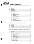
Table of Contents
Operator Safety Instructions ................................................................................ 3
Introduction .......................................................................................................... 4
Propane Safety Information .................................................................................. 5
How to Operate the Machine ............................................................................... 6
Maintenance and Adjustments ............................................................................. 6
Trouble Shooting .................................................................................................. 7
SECTION II - Parts Manual
Frame Assembly ................................................................................................ 10
Handle Assembly ............................................................................................... 12
Engine Assembly (Kawasaki FH 500 V "V" Twin) ............................................. 14
Engine Assembly (Kawasaki FH 381 V "V" Twin) ............................................. 16
Engine Assembly (20 HP Onan) ........................................................................ 18
12 Volt Fuel System ........................................................................................... 19
Fuel System ....................................................................................................... 20
Bearing Assembly 21", 24", 27" ......................................................................... 21
Jet-Stream Assembly Drawing .......................................................................... 22
Kawasaki Envirogard System IV ....................................................................... 24
Kawasaki Envirogard System III ........................................................................ 26
Pad Driver Assembly ......................................................................................... 28
Belt Selection Chart ........................................................................................... 29
Pulley Chart ....................................................................................................... 30
Electrical Schematic 120V AC System .............................................................. 31
Electrical Schematic 14 HP Single 12Vdc ......................................................... 32
Electrical Schematic 14 HP Single 12Vdc Envirogard III ................................... 33
Electrical Schematic 17 HP Twin 12Vdc ........................................................... 34
Electrical Schematic 17 HP Twin Envirogard .................................................... 35
Onan 12V DC Electrical Shcematic ................................................................... 36
DANGER: It is the owner/operator's responsibility to ensure that the air-exchange system
installed in any location where a propane floor care machine is being operated is of sufficient capacity and quality to support the use of such a machine. OSHA and other County,
State, or Federal Agencies publish guidelines on this subject that are usually most readily
found in the possession of the respective owners and/or parent companies of any location
or chain of locations. Failure on the part of the owner/operator to ensure that a propane
floor care machine can be operated safely in a given location may lead to injury, sickness
or even loss of life.
This Owner's Manual/Safety Procedures Guide has been prepared for the promotion of educational purposes only and
Clarke does not claim or assume any responsibility for the operator's actions or safety. To be completely aware of what
local authorities may require, contact the Fire Marshal of your community.
Page 2
Clarke® Propane Burnishers Operator's Manual
Engine Emissions and CO Safety
The purpose of this document is to provide information on:
· The potential effects of CO exposure;
· The methods to reduce the risk of CO poisoning;
· The methods used to determine the amount of potential exposure to CO produced by equipment.
DANGER: All LPG (Liquid Propane Gas) powered engines, including this engine, produce
Carbon Monoxide (CO). It is a LETHAL POISON that is a colorless, odorless, tasteless, and
non-irritating gas. It is produced by incomplete combustion of carbonaceous material such as
propane (LPG).
Failure to provide for proper venting of CO produced during the operation of combustion powered
engines may result in SERIOUS INJURY OR DEATH to the operator and those in the
contaminated area.
The effects of CO can be experienced at different exposure levels, depending on the health of the
individual. Conditions that affect the tolerance of the individual are smoking, age, temperature,
humidity, and other conditions.
WARNING: Read and understand The Operators Manual completely before using this machine
This document explains how CO produced can be managed to reduce the risk of carbon monoxide
poisoning.
All distributors, owners, and operators should be aware of the potential effects of CO and the
methods used to prevent over exposure.
ALTO U.S. is dedicated to our customers, their safety, and providing information, services, and
products that meet those needs.
Information provided in this document is current as of the date written November 1997.
I
Document Overview
The information provided in the following overview has been condensed to provide the
reader with a summary of the material presented.
Potential Effects of CO Exposure
·
Work place/industry guidelines for CO exposure limits vary substantially from
region to region (OSHA) Permissible Exposure Limit (PEL) for CO is 50 ppm, as an
8-hour time weighted average.
·
Definition of CO effects - The toxic effects of carbon monoxide in the blood are the
result of tissue hypoxia (lack of oxygen). The severity depends on the state of activity
of the individual and his tissue oxygen needs.
Methods to Reduce The Risks of CO Poisoning
·
Air Exchange and CO Diffusion - CO does not mix with air on its own. Air currents
can “stir” the CO and dilute the concentration values by mixing it with the available
air. When using equipment over a large area in a short time “stirring” occurs as you
walk.
·
Application Considerations (Burnishing versus Stripping) - When activity is
concentrated to a smaller area as in a stripping application, air “stirring” must be
forced by the use of fans to reduce the risk of high concentrations of CO.
·
Air Quality Monitoring – Deployment of a monitor/detector is essential for the safe
operation of any equipment that has the potential to produce CO.
·
Room Size and Time Estimations - The concentration and volume of CO
production, the size of the area and the amount of air exchange are factors involved
with determining safe time limits for operation in a specific room size.
·
Maintenance of Equipment - LPG engines are dependent on engine tune up, and air
filter replacement. CO concentration (production) skyrockets when the air to fuel
ratio becomes fuel rich. Follow the recommended Maintenance Schedule for the
engine.
·
Safety Equipment Available. - Envirogard automated fuel to air ratio monitoring
and regulation providing an optimum combustion, three-way type catalytic converter
to scrub CO, Hydro Carbons (HC), and Nitrous Oxide (NOx) from the engine exhaust
providing the lowest possible emissions, high cubic feet per minute (CFM) fans
(forced air mixing), and digital combustion analyzers for tail pipe emissions
monitoring.
II
Engine Emissions and CO Safety
Potential Effects of CO Exposure
·
·
Work place/industry guidelines for CO exposure limits
Definition of CO effects
Work place/industry guidelines for CO exposure limits
Limits for permissible exposure to CO vary substantially from region to region. City, State, and
Industry requirements should be consulted prior to use of any equipment.
The current Occupational Safety and Health Administration (OSHA) Permissible Exposure Limit
(PEL) for CO is 50 ppm, as an 8-hour time weighted average (TWA). This is computed by making
measurements at intervals over 8 hours, then adding the sums of the concentrations and the intervals, and
dividing by 8 hours. For example:
Time
8:00-9:00
9:00-10:00
10:00-11:00
11:00-12:00
12:00-1:00
1:00-2:00
2:00-3:00
3:00-4:00
Time intervals =
Interval
1 HR
1 HR
1 HR
1 HR
1 HR
1 HR
1 HR
1 HR
8 HR
ppm =
PPM
100
25
25
50
50
50
50
50
400
400ppm/8HR=50ppm TWA
The current National Institute for Occupational Health and Safety (NIOSH), immediately dangerous to
life and health concentration (IDLH) recommended level for CO is 1,200 ppm. NIOSH defines the IDLH
exposure level as the concentration that could result in irreversible health effects or death, or prevent escape
from the contaminated environment within 30 minutes.
Definition of CO effects
The toxic effects of carbon monoxide in the blood are the result of tissue hypoxia (lack of oxygen).
carbon monoxide combines with hemoglobin to form carboxyhemoglobin. Since CO and oxygen react with
the same group in the hemoglobin molecule, carboxyhemoglobin is incapable of carrying Oxygen. The
affinity of hemoglobin for CO is 200 to 240 times greater than for oxygen. The extent of saturation of
hemoglobin with CO depends on the concentration of the gas, the quantity of inspired air and on the time of
exposure. The severity depends on the state of activity of the individual and his tissue oxygen needs.
According to Harrison’s Principles of Internal Medicine 7th edition, no symptoms will develop at a
concentration of 0.01% CO (100ppm) in inspired air, since this will not raise blood saturation above 10 %.
Exposure to 0.05% (500ppm) for 1 hour during light activity will produce a blood concentration of 20%
carboxyhemoglobin and result in a mild or throbbing headache. Greater activity or longer exposure causes
a blood saturation of 30 to 50 %. At this point head ache, irritability, confusion, dizziness, visual
disturbance, nausea, vomiting, and fainting can be experienced. Exposure for one hour to concentrations of
0.1% (1000ppm) in inspired air the blood will contain 50 to 80% carboxyhemoglobin which results in
coma, convulsions, respiratory failure and death. On inhalation of high concentrations of CO, saturation of
the blood proceeds so rapidly that unconsciousness may occur suddenly without warning.
III
Methods to Reduce The Risks of CO Poisoning
·
·
·
·
·
·
Air Exchange and CO Diffusion
Application Considerations (Burnishing versus Stripping)
Air Quality Monitoring
Room Size and Time Estimations
Maintenance of Equipment
Safety Equipment Available
Air Exchange and CO Diffusion
The most reliable method to prevent CO Poisoning is to ensure all the CO produced is vented outside.
With wood stoves or gas heaters this is performed with ductwork that carries the exhaust and CO outside.
Non-stationary combustion type equipment must be used in such a way that CO is not allowed to rise to a
harmful or dangerous level.
CO does not readily dissipate or mix with air on its own. Air currents can “stir” the CO and dilute the
concentration or ppm values by mixing it with the available air. When using equipment over a large area in
a short time “stirring” occurs as you walk, or to say it another way, your Effective Operating Zone is large.
When activity is concentrated to a smaller area as in a stripping application, the Effective Operating Zone is
small, and “stirring” must be forced by the use of fans to increase the Effective Operating Zone and reduce
high concentrations of CO.
Air exchange rates (air exchange is defined as the exhausting of internal air to the external
atmosphere), the size of the Effective Operating Zone, amount of CO produced, level of human activity,
and the duration of exposure are all factors in the determination of the production of carboxyhemoglobin
and the amount of CO blood saturation.
Application considerations (Burnishing versus Stripping)
When using equipment over a large area in a short time, as in most burnishing applications, your
Effective Operating Zone is large. When activity is concentrated to a smaller area as in stripping
applications, the Effective Operating Zone is small and stirring or CO mixing MUST be forced by the use
of fans to increase the Effective Operating Zone and reduce high concentrations of CO.
Caution: air mixing in itself may not be sufficient to reduce CO to a safe level.
The Effective Operating Zone can be defined as the area covered in a given time.
Stripping is quite a different type of operation than burnishing, and carries with it substantially more
hazards, as stripping is a low movement operation compared to burnishing (less floor space for the same
time). As shown in Model 1, the CO concentrations rise much quicker as the “Effective Operating Zone” is
a very small area compared to the total building size.
IV
Notice the CO concentration and the Effective Operating Zone with air exchange. The CO cloud is still
concentrated in a small area. Note the “Dividing Zone” shown above, this is the line where airflow changes
direction. In Model 2, air changes are cut in ½ as little or no CO crosses the Dividing Zone to be exhausted.
Notice the CO concentration and the Effective Operating Zone (Expanded to the Dividing zone) with
air exchange and forced air mixing. The CO cloud is still concentrated on one side of the Dividing zone.
Note the “Dividing Zone” shown above, this is the line where airflow changes direction. In Model 3, air
changes are cut in ½ as little or no CO crosses the Dividing Zone to be exhausted.
Notice the CO concentration and the Effective Operating Zone (Expanded through the Dividing zone
to the second vent) with air exchange and forced air mixing through the dividing Zone. The CO cloud is
diluted with the available air in the building. Note the “Dividing Zone” shown above, this is the line where
airflow changes direction. In Model 4, air changes are full as forced air mixing has moved and mixed the
CO between all air zones.
V
Air Quality Monitoring
Warning
Deployment of a monitor/detector is essential for the safe operation of any equipment
that has the potential to produce CO. CO sensors/detectors became available on the mass market around
1978. At present several brands sell in the fifty-dollar range. The main differences between the
technologies involved are battery or electric and Semiconductor or Biomimetic types. Detectors for carbon
monoxide (CO) are manufactured and marketed for use in either the home or occupational industrial
settings. The detectors for home use are devices that will sound an alarm before CO concentrations in the
home become hazardous. There is an Underwriters Laboratories, Inc., performance standard (UL 2034) for
residential CO detectors. Detectors currently available on the market are battery-powered, plug-in, or hardwired. Some models incorporate a visual display of the parts per million (ppm) concentration of CO present
in the home. For more information on CO detectors for home use, call the Consumer Product Safety
Commission Hotline at 1-800-638-2772.
CO detectors for use in residential settings are not designed for use in typical workplace settings.
Monitoring requirements in an occupational setting are different from monitoring requirements in the
home. In the workplace, it is frequently necessary to monitor a worker's exposure to carbon monoxide over
an entire work shift and determine the time-weighted average (TWA) concentration of the exposure. It may
also be necessary to have carbon monoxide monitors with alarm capabilities in the workplace. The directreading instruments are frequently equipped with audio and/or visual alarms and may be used for area
and/or personal exposure monitoring. Some have microprocessors and memory for storing CO
concentration readings taken during the day. It is significant to note that some of the devices mentioned for
workplace CO monitoring are not capable of monitoring TWAs, and not all are equipped with alarms. The
appropriate monitor must be chosen on an application-by-application basis. For more information on the
availability of workplace CO monitors or their application, call the National Institute for Occupational
Safety and Health at 1-800-35-NIOSH (1-800-356-4674).
Room Size and Time Estimations for Parts Per Million (PPM) CO
The fundamental factors in area CO levels involve:
The concentration and volume of CO production;
The size of the area;
The amount of *air exchange if any;
The amount of time CO is produced.
Multiplying length, width, and height will determine the volume or cubic feet in a room. So an empty
building 100ft by 100ft with a 10ft ceiling would be 100,000 cubic ft. in size. Any material that is in the
room and takes space would reduce the cubic feet.
*Air exchange is defined as the exhausting of internal air to the external atmosphere.
The Graph above depicts the relationships of air exchange to time and CO ppm with cubic feet
area and percent CO emissions remaining constant.
PPM
1 .5 %
5
4
4
3
3
2
2
1
1
0
5
0
5
0
5
0
5
0
5
C O
E m is s io n
in
1 0 0 ,0 0 0 c u b ic fe e t w ith 4 8 0 c c
c o m p le te a ir /C O m ix in g
1 4
H P
0
0
0
0
0
0
0
0
0
0
0
E n g in e
a n d
0 .0 c h a n g e /h r
1 /2 c h a n g e /h r
1 c h a n g e s /h r
2 c h a n g e s /h r
0
.5
1
2
3
T im e
4
5
(h o u rs )
VI
6
7
8
9
8 HourTime Weighted Average (OSHA Method)
1.5 %CO 100,000cf
Hours Operation 1
2
3
4
5
6
7
8
TWA (OSHA Method)
0 change/hr
34 103 206 343 514 719 959 1232
1/2 change/hr
27 70 124 183 246 311 378 445
1 changes/hr
22 51 84 118 152 186 220 255
2 changes/hr
15 32 49 66 83 100 117 135
Based on the CO production rates shown above the TWA would be exceeded in a 100 x 100 x 10
foot (empty) space after 3 hours with 2 air changes per hour. (Assumes no additional CO exposure
during 8 hour time period)
1 .5 %
C O
E m is s io n in 5 0 0 ,0 0 0 c u b ic fe e t w ith 4 8 0 c c
E n g in e a n d c o m p le te a ir /C O m ix in g
1 4
H P
5 0 0
4 5 0
4 0 0
3 5 0
0 .0 c h a n g e
1 /2 c h a n g e
1 c h a n g e s /
2 c h a n g e s /
PPM
3 0 0
2 5 0
2 0 0
1 5 0
/h r
/h r
h r
h r
1 0 0
5 0
0
0
1
2
3
4
5
T im e
6
7
8
9
1 0
(h o u rs )
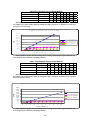
The Graph above depicts the relationships of air exchange to time and CO ppm with cubic feet
area and percent CO emissions remaining constant.
8 Hour Time Weighted Average (OSHA Method)
1.5 %CO 500,000cf Hours Operation 1
2
3
4
5
TWA (OSHA Method)
0 change/hr
17 51 103 171 257
1/2 change/hr
14
35
62
92
123
6
360
7
8
479 616
156
189 223
1 changes/hr
11 26 42 59 76
93 110 127
2 changes/hr
7 16 24 33 42
50
59 67
Based on the CO production rates shown above the TWA would be exceeded in a 100 x 500 x 10
foot (empty) space after 6 hours with 2 air changes per hour. (Assumes no additional CO exposure
during 8 hour time period)
PPM
1 .5 % C O E m is s io n in 7 5 0 ,0 0 0 c u b ic fe e t w it h 4 8 0 c c 1 4 H P E n g in e a n d c o m p le te a ir /C O m ix in g
5
4
4
3
3
2
2
1
1
0
5
0
5
0
5
0
5
0
5
0
0
0
0
0
0
0
0
0
0
0
0
1
1
2
0
1
2
3
4
5
6
7
8
9
.0 c h a n g e /h r
/2 c h a n g e /h r
c h a n g e s /h r
c h a n g e s /h r
10
T im e (h o u r s )
The Graph above depicts the relationships of air exchange to time and CO ppm with cubic feet
area and percent CO emissions remaining constant.
VII
8 Hour Time Weighted Average (OSHA Method)
1.5 %CO 750,000cf Hours Operation 1 2 3
4 5 6
7
8
TWA (OSHA Method)
0 change/hr
5 14 27 46 69 96 128 164
1/2 change/hr
4 9 16 24 33 42 50 59
1 changes/hr
3 7 11 16 20 25 29 34
2 changes/hr
2 4 7
9 11 13 16 18
Based on the CO production rates shown above the TWA would not be exceeded in a
100 x 750 x 10 foot (empty) space after 8 hours with 2 air changes per hour. (Assumes no
additional CO exposure during 8 hour time period)
Maintenance of Equipment
Warning
The proper maintenance of equipment is vital to safe operation. LPG engines are
dependent on engine tune up, and air filter replacement. CO concentration (production) skyrockets when
the air to fuel ratio becomes fuel rich. Follow the recommended Maintenance Schedule for the engine
found in the Engine Operator/Owner Manual as well as the Maintenance And Adjustments schedule found
in the Propane Floor Equipment Operator’s Manual that were supplied with the equipment. Additional
manuals may be obtained by contacting Clarke at 1-800-545-3454 or write to Clarke Customer Service,
2100 Hwy. 265, Springdale AR 72764.
·
·
·
·
CO Safety Equipment Available
Envirogard automated fuel to air ratio monitoring and regulation providing an optimum combustion
Three-way type catalytic converter to scrub CO, Hydro Carbons (HC), and Nitrous Oxide (NOx) from
the engine exhaust providing the lowest possible emissions
High cubic feet per minute (CFM) fans (forced air mixing)
Digital combustion analyzers for tail pipe emissions monitoring
VIII
IX
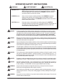
OPERATOR SAFETY INSTRUCTIONS
WARNING
AVERTISSEMENT
ADVERTENCIA
DANGER means:
Severe bodily injury or death can occur to you or other personnel if the DANGER statements found on this machine or in this Owner's Manual are ignored
or are not adhered to. Read and observe all DANGER statements found in
this Owner's Manual and on your machine.
WARNING means:
Injury can occur to you or to other personnel if the WARNING statements
found on your machine or in this Owner's Manual are ignored or are not
adhered to. Read and observe all WARNING statements found in this Owner's
Manual and on your machine.
CAUTION means:
Damage can occur to the machine or to other property if the CAUTION
statements found on your machine or in this Owner's Manual are ignored or are
not adhered to. Read and observe all CAUTION statements found in this
Owner's Manual and on your machine.
DANGER:
Failure to read the Owner's Manual prior to operating or attempting any service or maintenance procedure to your Clarke machine could result in injury to you or to other personnel;
damage to the machine or to other property could occur as well. You must have training in
the operation of this machine before using it. If you or your operator(s) cannot read
English, have this manual explained fully before attempting to operate this machine.
DANGER:
Moving parts of this machine can cause serious injury and/or damage. Do not allow contact
of clothing, hair, hands, feet, or other body parts with the rotating pad. Keep other people away
from the machine while it's in operation.
DANGER:
Injury to the operator or bystanders could occur if the machine's power is on while changing
the buffing pad or making machine adjustments. Never try to change the buffing pad or attempt
to make machine adjustments while the engine is running.
DANGER:
Cigarette lighters, pilot lights and any other source of ignition can create an explosion if it comes
in contact with propane. Propane is a highly flammable fuel. All sources of ignition should be
extinguished or removed entirely if possible from the work area. DO NOT SMOKE in the vicinity
of a propane buffer.
DANGER:
This machine emits carbon monoxide. Asphyxiation could occur if the unit is used in an area
with poor or inadequate ventilation. Operate machine in a well ventilated area only. If a
headache develops, shut off the machine. Have it checked for carbon monoxide emissions
by a qualified shop before using it again.
DANGER:
Dangerous carbon monoxide emissions from this machine are greatly increased due to a dirty
combustion air cleaner. Follow the engine's manufactureres air cleaner service instructions.
DANGER:
Propane is highly flammable. If you smell propane gas, shut off the machine and move it
outside. Determine the source of the leak before using it again. NEVER vent propane gas
inside a building. It is UNLAWFUL to store a propane bottle inside a building.
WARNING:
Long or continuous exposure to high noise levels may cause permanent hearing loss.
Always wear hearing protection while using this machine.
WARNING:
Injury to the eyes and/or body can occur if protective clothing and/or equipment is not worn
while using this machine. Always wear safety goggles and safety clothing while using this
machine.
WARNING:
Severe burn or injury could occur if you touch the hot muffler or exhaust pipe. Do not touch
the hot muffler or exhaust pipe.
Clarke® Propane Burnishers Operator's Manual
Page 3
WARNING:
Any alterations or modifications of this machine could result in damage to the machine or injury
to the operator or other bystanders. Alterations or modifications not authorized by the
manufacturer voids any and all warranties and liabilities.
WARNING:
To avoid injury or property damage, do not leave the machine where it can be tampered with
or started by persons untrained in its operation. You must have training in the operation of
this machine before using it. DO NOT leave the machine running unattended.
WARNING:
Substantial damage to the floor, the machine, or personnel may result if the machine is
operated with the pad off center, damaged or missing. Do not operate the machine if the pad
is off center, damaged or missing.
WARNING:
Operating a machine that has loose parts could result in injury or property damage. Do not
operate this machine if there are loose parts. Inspect the machine for loose parts frequently.
This will promote safe operation and a long life for the machine.
WARNING:
Vibration from machinery may cause numbness or tingling of the fingers in certain people.
Smoking, dampness, diet, and heredity may contribute to the symptoms. Wearing warm
clothing, gloves, exercising and refraining from smoking can reduce the effects of vibration.
If the symptoms still persist, discontinue operation of the machine.
WARNING:
Onan Machines. Insulation installed in the new muffler may become loosed in the initial few
hours of operation. This material will lodge in spark arrester in the muffler exit port. Onan
requires that the spark arrester be removed and cleared of all debris after the first five hours
of operation and as part of regular maintenance. Failure to perform this maintenance can rfesult
in severe engine over-heating.
Introduction
Clarke propane floor care equipment is manufactured in
two basic concepts: the buffer/burnisher and the floor
stripper. Both of these designs are truly PORTABLE
equipment. Propane buffers are best defined as ultra
high speed buffers with the staying power to produce
superior high gloss floor surfaces. Upon contact with the
floor, the buffer should always be kept moving. The
speed at which you walk will determine the results that
you will obtain. Slower speeds create more heat and
therefore more shine. Clarke recommends a moderate
pace for best results and safe operation. NEVER RUN
WITH THE BUFFER!! While a credible shine will still
result, the danger of trying to stop the machine in an
emergency situation is unacceptable. When buffing,
avoid loose tile, electric outlets, door thresholds and any
object which may come in contact with the pad other than
the floor itself. REMEMBER, the pad is turning very
rapidly.
Proper care and maintenance will protect your investment and keep your machine serving you for many years
to come. It is essential that these issues are closely
followed:
CAUTION:
Page 4
In addition, overfilling allows liquid propane to
enter the fuel control system, possibly ruining
the lockoff/regulator assembly. This voids the
warranty on affected parts of the machine. To
avoid problems, read and understand fully, the
section "Filling and Storing Propane Tanks."
OVERHEATING is a major cause of engine failure.
Keep the cooling air bonnet filter clean. Protect your
machine; don't allow wax dust/lint to build up on the
cooling fins of the engine cylinder(s). A good high
pressure spray wash directed at the fins when the
engine is cold will prevent this from happening.
LOW OIL AND DIRTY OIL account for most of the
other failures. Clarke recommends changing the oil
on a regular schedule, perhaps exceeding that
which is found in the engine manufacturers' manual.
Checking the oil daily, before putting the machine to
work, is a good habit to get into and could save you
the downtime and expense of replacing the engine
due to oil starvation. AFTER AN OIL CHANGE, MAKE
SURE YOU HAVE REPLACED THE OIL SUPPLY
BEFORE RESTARTING THE ENGINE.
Overfilling the propane tank is the
number one cause of problems with a
propane machine. This can cause
the engine to run poorly or not at all.
Clarke® Propane Burnishers Operator's Manual
Propane Safety Information
Facts About LP Gas - Propane
As a fuel, Propane gas is unmatched for both safety and
dependability. It has been used as a domestic household
fuel for over half a century, and for over thirty years as an
internal combustion engine fuel. Propane is a highly
flammable fuel that is contained under pressure as a
liquid. Vaporized gas has a similar explosive force to
gasoline and mixtures as low as 2% LP Gas to air may be
ignited in a closed environment. Care should be
exercised to avoid escaping vapor as it can freeze skin
and cause frost bite. Vaporized fuel is heavier than air and
will collect in the lowest confined space available.
Facts About Propane Tanks
Propane tanks are constructed according to ASME or
Federal DOT #4ET20 pressure safety codes. Including the
tank, all valves and fittings are UL Listed. Propane gas is
noncorrosive and will not rust the inside of a tank. Should
the tank exterior become damaged or rusted, discontinue
use. DO NOT tamper with tank gauges or safety relief
valves. NEVER use a tank not intended for use with a
propane buffer. DO NOT substitute tanks that are used
with a barbecue grill, etc. A. L. Cook recommends having
propane tanks tested once a year by an authorized
National LP Gas Association sanctioned propane dealer.
The fuel tank is supplied directly from the manufacturer
and is void of fuel. This tank must be purged at the time of
the first fill. Local fuel vendors should be familiar with this
operation and will provide this service.
Recommended Purge Procedures
How to purge new LP-Gas Buffer cylinders equipped with
the Overfill Prevention Device:
New containers may contain vapor, air, or other
contaminants. It is essential that these be removed before
filling the container and placing it into service. Air in the
container will cause abnormally high pressure, with the
result that the pressure relief valve may open. Air in the
system is also likely to cause lean mixture, making
ignition difficult. If a cylinder is suspected of being
depressurized or open to the atmosphere for a period of
time, it must be re-purged as if it were a new container.
To purge a container, the following steps should be
taken.
Purging of containers should be performed in an approved
area (see NFPA #5 8) using NPGA #13 3.89(a) procedure.
1.
2.
Determine if the container pressure is zero. Should the
cylinder contain only pressurized air, the air may be vented
directly to the atmosphere through the service valve using an
adapter and the outage valve.
Pressurize the container to approximately 15 psig with LPgas vapor. Never purge with liquid LP-gas! To do so
will cause the moisture vapor to chill and remain in the
cylinder. LPgas liquid also expands 270 times to
vapor making the purge process ineffective. Use LPgas vapor only!
Clarke® Propane Burnishers Operator's Manual
3.
Make the connection to the quick coupler (A purge manifold
system is most effective). Fully open the cylinder service
valve as well as the outage valve. Vent to a safe atmosphere. A vent stack is recommended.
4.
On Overfill Prevention Device cylinders, the purge time is
increased as a result of the new valve design. Opening the
outage valve will help improve the speed of the purge.
5.
Repeat #3 and #4 for a total of FIVE purges.
6.
Repressurize the container with odorized LP-gas vapor to 15
psig.
7.
The container is now ready to be filled with LP-gas.
8.
Once filled, check all fittings and tank openings for leaks
using an approved leak detector solution.
9.
The container is now ready to be placed in service. Add
DOT and OSHA labels.
Symptoms of a non-purge cylinder:
• Relief valve opens due to over pressurized
cylinder creating hazardous situation.
• Moisture in the cylinder.
• Buffer operates initially but shuts down when
fuel mixture becomes too lean.
Refilling & Storing Propane Tanks
The NFPA Technical Committee prohibits the storage of
such containers in buildings. There are few exceptions to
this rule. In other words, propane tanks should NOT be
stored in buildings used by the public or frequented by
anyone passing through or who is working in the building.
Full or empty, never leave tanks in small enclosed areas.
The tank(s) must be in a secure, tamper-proof storage
enclosure that provides safety from accident or vandalism.
PROPANE TANKS SHOULD ALWAYS BE
TRANSPORTED, INSTALLED AND USED IN AN
UPRIGHT POSITION.
OVERFILLING PROPANE TANKS IS HAZARDOUS.
The tank should NEVER be completely filled with liquid
propane. 80% of the total tank volume is to be considered
at ALL times as full. EXPANSION MUST BE ALLOWED
FOR. Propane Buffer tanks are equipped with a fixed
liquid level gauge which contacts the liquid level at 80% of
container capacity, allowing 20% for expansion. The top
part of this device must be unscrewed counterclockwise
so that vapor can escape through the small hole it its side,
as the tank is refilled. When the escaping vapor starts to
give way to liquid, the device must be quickly closed and
the propane nozzle turned off.
**IMPORTANT** The engine and the fuel system on
your floor care machine are designed to run on fuel
vapor, not fuel liquid. Overfilling the propane tank will
result in damaging the lockoff and/or regulator. This will
VOID the WARRANTY on these components.
Page 5
How to Operate the Machine
Maintenance And Adjustments
Preparing The Machine For Use
Emission Control Information
BEFORE using any type of powered equipment, proper safety
dictates you should visually inspect it.
1. Adjust the HANDLE to a comfortable height and tighten the
bolts to 30-50- ft/lbs.
2. BONNET FILTER - Make sure the bonnet air filter atop the
engine is clean. It should be changed hourly and thoroughly
cleaned before reuse.
3. Check the engine OIL LEVEL. Make sure the machine is in a
level position.
** HONDA - DO NOT screw the dipstick in to get reading.
**KAWASAKI - DO NOT screw the dipstick in to get reading.
4. Fill the tank following the instructions as given under the
previous heading: "Refilling And Storing Propane Tanks." In
addition, if your buffer came with an "80% Safety Fill Tank"
then it should ONLY be filled through the threaded valve with
the larger diameter that is covered by a yellow cap to ensure
a "Full" level that is safe.
5. PAD AND PAD HOLDER - Inspect the condition of the pad and
pad holder. Is there a pad? Is it properly attached? What is its
condition? Ensure the pad is clean and has at least a
thickness of 1/3 inch. ALWAYS turn off the engine to clean or
replace pad.
6. TANK and FUEL LINES - The tank has already been covered
but do the fuel lines show any sign of wear and tear, such as
cracks or any corrosion? Screw the brass fuel line fitting onto
the tank service valve hand tight only. This connection MUST
be secure because the service valve has a safety valve inside
it which will only open if the brass fuel line fitting is COMPLETELY seated into the service valve.
To protect the environment in which we will live, the manufacturer
has incorporated crankcase emission (1) and exhaust emission
(2) control systems (EM) in compliance with applicable regulations
of the United States Environmental Protection Agency and
California Air Resources Board.
1. Crankcase Emission Control System. A sealed-type
Starting the Engine
1.
2.
Plug in 110 volt starter cord on models so equipped.
We recommend setting the throttle on models with 110 volt
starter to the following positions:
** HONDA - Set throttle/choke to the "choke" position.
**KAWASAKI - The KAWASAKI single cylinder and Kawasaki
twin cylinder engines are designed to be started in the IDLE
throttle position. This creates a vacuum necessary to open
the lock-off valve inside the regulator. Actuation of the throttle
lever will keep the lock-off valve from opening and the engine
from getting fuel so the engine will not start. Proper maintenance will insure easy starting.
3. Open (counterclockwise) the service valve on the propane
tank about one and a half turns.
4. Ensure the buffer is tilted back so that the pad is off the floor
on all machines without a clutch.
5. Engage starter for a MAXIMUM of 5 to 6 seconds or until the
engine fires. Serious starter damage will result if this is
exceeded and the warranty may not apply.
6. Open the "choke" until the engine runs smoothly. (HONDA
ONLY)
7. Operate the engine at half throttle for approximately two
minutes for proper warm-up. Then advance to full throttle for
best results.
NOTE: If the engine refuses to start, see the Trouble Shooting Guide.
crankcase emission control system is used to eliminate
blow-by gases. The blow-by gases are led to the
breather chamber through the crankcase. Then, it is led
to the air cleaner. Oil is separated from the gases while
passing through the inside of the breather chamber
from the crankcase, and then returned back to the
bottom of crankcase.
2. Exhaust Emission Control System. The exhaust
emission control system applied to this engine consists
of a carburetor and an ignition system having optimum
ignition timing characteristics. The carburetor has been
calibrated to provide lean air/fuel mixture characteristics
and optimum fuel economy with a suitable air cleaner
and exhaust system.
Tampering w/Emission Control System Prohibited
Federal law and California State law prohibits the following acts or
the causing thereof: (1) the removal or rendering inoperative by
any person other than for purposes of maintenance, repair, or
replacement, of any device or element of design incorporated into
any new engine for the purpose of emission control prior to its sale
or delivery to the ultimate purchaser or while it is in use, or (2) the
use of the engine after such device or element of design has been
removed or rendered inoperative by any person.
Among those acts presumed to constitute tampering are the acts
listed below:
Do not tamper with the original emission related part.
>Carburetor and internal parts
>Spark plugs
>Magneto or electronic ignition system
>Fuel filter element
>Air cleaner elements
>Crankcase
>Cylinder heads
>Breather chamber and internal parts
>Intake pipe and tube
General Maintenance and Adjustments
1. Fuel control system. To ensure personal safety,
adjustments should ONLY be made by a qualified LPG
system technician or an authorized service center,
using an exhaust gas analyzer. Do not operate the
machine if carbon monoxide levels exceed OSHA
standards.
Stopping The Engine
2. Pad replacement. Tilt the machine back on its rear
1. Close (clockwise) the service valve on the propane tank.
caster to reach the pad centering device. Turn the outer
2. ALWAYS allow the engine to run until it stops from lack of fuel.
ring counterclockwise to remove it. Remove the old
** ONLY IN AN EMERGENCY should the "stop" position on a
pad. Install the new pad by carefully centering it
HONDA throttle or the "kill switch" on a KAWASAKI and ONAN
models be used.
against the "harpoon hook" plastic gripper. Replace the
3. Disconnect the fuel line from the tank.
center locking ring. Check rotation of the pad driver.
4. REMEMBER, when you are finished with the machine, store
Eccentricity of the pad should not exceed 1/4 of an inch.
the propane tank outside the building, in a safe place away
from heat or direct sunlight.
Page 6
Clarke® Propane Burnishers Operator's Manual
Maintenance And Adjustments
3. Belt replacement. Tilt the machine on its side
(observing the following precautions) and block
securely.
**KAWASAKI and HONDA single cylinder - Do not
turn the carburetor side down. Oil will enter the
intake manifold and may cause engine damage. Turn
the machines with the exhaust side down.
**KAWASAKI twin cylinder - Do not tilt the machine on
its nose as this is where the carburetor is located. It is
okay to turn this model on either its left or right side.
(a) Remove pad.
(b) Use a suitable wrench to secure the top of the
shaft and spin off the pad driver and remove it
from the machine.
(c) Remove old belt carefully and completely.
(d) Install new belt and adjust the pressure of the
Lovejoy tensioner.
(e) Reinstall pad driver.
Recommended 20 Hour Maintenance Items >Change engine oil.
>Check pad driver for loose parts.
>Check belt for wear or slippage.
>Check engine pulley for tightness.
>Check wheel bolts.
>Check engine mount bolts.
>Check handle bolts.
>Check for leakage of engine oil at the various seals.
Recommended Oil Change Intervals
Do not exceed the 20 hour oil change interval. Oil
changes more frequent than 20 hours will give even
longer engine life. In any case, always use 30HD or
10W30 engine oil with all of the following ratings: SF, SG,
CC. The various engines have different oil sump capacities. Make sure the oil level is maintained at the "FULL"
level.
Recommended 200 Hour Maintenance
Return machine to authorized service center for overall
checkup.
Clarke® Propane Burnishers Operator's Manual
Trouble Shooting
When troubles occur, be sure to check the simple causes
which at first, may seem too obvious to be considered.
For example, a starting problem could be caused by fuel
starvation due to an empty propane cylinder or an
unopened service valve. If you don't check for this, starter
burnout could result.
1. KAWASAKI - "SURGING IDLE" - To smooth out the
engines' idle characteristics, adjustment is provided
by an idle screw on the lower left side of the carburetor as viewed from the operator's position. The screw
is bright steel and 1/4" in diameter with a Phillips
head on it. Rotating the screw clockwise will increase
the idle speed and this should cure the "surging idle".
IF IT DOES NOT, call our customer service department for assistance.
2. EXCESSIVE VIBRATION - Look for the following
possibilities:
(1) Pad is off center. Remove and reinstall.
(2) Pad Driver is bent or cracked. (Possibly from
striking a curb or bolt in the floor.) Replace
immediately with a new part only.
(3) Bearings in Front End Assembly are worn. Place
machine on its side where the muffler is
mounted. Grip Pad Driver and move up, down
and from side to side to check for slack in the
bearings. If this is the case, then to effect a
proper repair, the bearings should be replaced
and possibly the shaft.
(4) Check to see if the bolts on shaft housing are
tight. Look to see if the nuts, bolts and spacers
on the Flex Coupler Assembly are all in place
and tight.
3. ENGINE STARTS AND IDLES, BUT WILL QUIT AS
THE THROTTLE IS ADVANCED - It is possible that
the propane tank's service valve is faulty. To check
for this, close the valve completely and then reopen
very slowly while you listen for a "click" when the gas
begins to travel through the valve. If you hear this
very slight noise, then what is happening is the valve
is only partially opening. This allows enough gas
through to start and idle the engine, but not enough
for full throttle operation. As the throttle is increased,
allowing more air to enter the intake, the engine will
quit from fuel starvation. Call your dealer or the
factory for instructions on where to have the service
valve replaced. Meanwhile, to get by, you can
continue to open the service valve until you don't hear
a "click" and then the engine will run normally. IF IT
DOES NOT, call our customer service department for
further assistance.
4. THE BUFFER SEEMS TO RUN WELL BUT DIES
DOWN WHEN THE PAD IS PLACED ON THE
FLOOR OR SOON THEREAFTER - Check for the
same problem as in #3.
5. EXCESSIVE NOISE FROM UNDER BUFFER - If this
problem has developed after use of the machine from
new, then the first place to check is the Lovejoy
Tensioner. As a new belt wears in, it naturally
stretches a bit and the tensioner will begin to rattle.
Place the buffer on its side (with the muffler down)
and reset by taking up the slack in the belt and tighten
the Lovejoy Tensioner.
Page 7
Trouble Shooting
6. STARTER WILL HARDLY TURN THE ENGINE
OVER or THE SOLENOID JUST CLICKS ON 12
VOLT OPTION MODELS - The battery is likely low in
charge. This can be remedied by recharging the
battery using a 12 volt battery charger at 4-12
amperes. The battery is located under the frame at
the rear of the buffer. The positive post is the one
with the RED cable attached to it. Follow the
instructions that came with the battery charger.
REMINDER: this will continue to happen unless the
buffer's engine is run for sufficient time between
starts to recharge the battery.
7. KAWASAKI V-TWIN - ENGINE BACKFIRES
LOUDLY AND REGULARLY SUDDENLY - Check
the sparkplug boots. One of them is likely cracked,
possibly due to contacting a corner of a shelf or a
door frame. Remove the sparkplug lead from the
sparkplug and replace the boot with a new one. The
engine should now run normally. IF IT DOES NOT
contact our customer service department for further
assistance.
8. KAWASAKI SINGLE CYLINDER - HARD STARTING
- You've tried the normal methods and the engine still
refuses to start and run. Remove the fuel hose from
the cylinder and press in on the valve which is inside
the quick coupler fitting on the end of the hose. This
will release the built up pressure in the system and
care should be taken not to be "burned" by the
escaping gas. Then reattach the fuel line to the
propane cylinder but DO NOT open the service valve.
Set the throttle at approximately 1/2 and press the
starter button. Allow the engine to turn over about 2 or
3 times and then open service valve at least 1½ full
turns. The engine should now be running. IF IT
DOES NOT, contact our customer service department
for further assistance.
NOTES
Page 8
Clarke® Propane Burnishers Operator's Manual
Propane Floor
Burnisher Equipment
Section II
Parts Manual
(70076A)
Clarke® Propane Burnishers Operator's Manual
Page 9
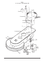
Clarke®
21", 24" and 27" Frame Assemby 7/03
7
6
5
4
3
2
1
19B
8
15
11
12
13
25
24
9
10
25
17
A
16
19A
22
18
19C
14A
14B
B
C
21
Page 10
20A
20B
20C
20
Clarke® Propane Burnishers Operator's Manual
Clarke®
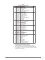
21", 24" and 27" Frame Assembly 7/03
Ref #
1
2
3
4
5
6
7
8
9
10
11
12
13
14A
14B
15
16
17
18
19
19A
19B
19C
20
20A
20B
20C
20D
21
22
23
24
25
Part No. Description
60056A Frame, 21" (W50-21)
60053A Frame, 24" (W50-24)
60054A Frame, 27" (W500)
98448A Nut, Lock, Flg, 7/16 -14
170860 Washer, Flat, 5/16
98462A Screw, Hex, 5/16 -18 x 1.25
60013A Carrier, Bottle (W30)
60006A Guard, Switch
98613A Felt (W31)
98648A Caster, Rear (W531)
170886 Washer, Flat, ¼
920110 Nut, Lock, 5/16 -18
98456A Bolt (all except Onan), M8-1.25 x 50
88305A Bolt (Onan only), M10-1.25 x 50
980652 Lock Washer (all except Onan), 5/16
98451A Lock Washer (Onan only), 7/16
980210 Washer, Flat (all except Onan)
87038A Washer, Flat (Onan only)
98650A Tensioner, Small Includes
98973A Tensioner, Large a, b, c
(used on 20Hp Onan machine)
77335A Label, Maintenance
58539A Spacer (all except Onan)
98586A Washer, Clutch (Onan only)
98651A Pulley
170857 Nut (all except Onan), ½-13
10633A Wheel Bracket Kit (incl. 19a,19b,19c)
99074A Bracket, Wheel
98447A Bolts, Flat Head, 5/16 -18 x 1.50
920110 Nuts, Lock, 5/16 -18
10630A Wheel/Axel Asm. (incl. 20a, 20b, 20c)
10058A Kit, 6" wheel ONAN (incl. 20a,20b,20d)
920248 Nut, 3/8 -16
98445A Screw, Hex, 3/8 -16 x 2.50
98629A Standard Wheel
50397A Wheel, 6" ONAN
98436A Bumper Strip
70468A Label, Clarke
77334A Label, Engine Tipping
77336A Label, Danger
70467A Label, Div. of ALTO
Clarke® Propane Burnishers Operator's Manual
{
}
Qty
1
1
1
1
4
4
1
1
2 ft.
1
4
4
1
1
1
1
1
1
( 1)
( 1)
1
1
2
1
1
1
2
8
8
2
2
(2)
(2)
(2)
2
6 ft.
1
1
1
2
Page 11
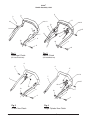
Clarke®
Handle Assembly 8/00
6
3
2
17
6
10
14
13
1
12
4
15
11
16
7
18
8
19
19
8
9
9
Fig. 1
Centrifugal Clutch
Fig. 2
Electric Clutch
(UL listed machines)
(UL listed Machine)
6
15
6
17
14
14
7
7
15
4
16
16
19
18
8
4
4
19
8
9
9
Fig. 3
V-Twin Non-Clutch
Page 12
Fig. 4
Single Cylinder Non-Clutch
Clarke® Propane Burnishers Operator's Manual
Clarke®
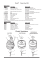
Handle Assembly 8/00
Ref # Part No.
1a
50024A
1b
2
3
4
5
6
7
8
9
10
11
12
13
14a
14b
14c
14d
15
16
17
18
19
Qty
(1)
52960A
98487A
98618A
52041A
Description
Cable, U.L. Throttles KAW. Twins
(W710)
Cable, Throttle KAW. Single
Screw, #8 x 0.75
Lever, Bar, U.L. (W40U)
Plug, ½ Button
98622A
98617A
98468A
85735A
98497A
98717A
98619A
98563A
50289A
50290A
98744A
98745B
85702A
81102A
962559
50767A
98469A
Grip Tube, Handle (W431)
Handle, Upper (W40)
Washer, Flat, ½
Screw, Hex, ½ -13 x 1.25
Washer, 3/16
Wire, (B006)
Handle, Upper U.L. (W401)
Switch, Electric Clutch (W08)
Cable, Kaw. 14 Non-Clutch w/Electric Clutch
Cable, Kaw. 17 Non Clutch w/Electric Clutch
Cable, Honda
Cable, Onan, UL
Screw, Hex, ¼ - 20 x 1.75
Nut, Lock, ¼ -20
Screw, Hex
Bracket
Washer, EXT. Tooth
1
1
2
2
1
3’
1
1
1
1
1
1
1
1
2
1
2
Clarke® Propane Burnishers Operator's Manual
(1)
1
1
1
Page 13
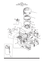
Clarke®
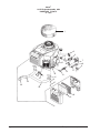
Engine Assembly 7/03
KAWASAKI FH451 V and FH500V
"V" Twin
Page 14
Clarke® Propane Burnishers Operator's Manual
Clarke®
Engine Assembly 7/03
KAWASAKI FH451 V and FH500V
"V" Twin
Ref #
1
2
3
4
5
6
7
8
9
10
11
11a
12
13
14
14A
15
16
17
18
19
20
21
21a
22
23
24
25
26
28
29
30
31
32
33
34
35
36
37
38
39
40
NI
NI
Part No.
50028A
60047A
920110
170860
98978A
52553A
47436A
852841
50360A
50027A
50001A
50937A
60003A
98756A
98805A
50239A
962559
50023A
980652
80049A
50003A
50017A
50002A
50894A
60010A
85737A
50019A
50004A
60062A
424704
964060
980652
60017A
98751A
50021A
50005A
86108A
80074A
80073A
60209A
98755A
57161A
70139A
70137A
Description
Bonnet KAWASAKI
Bonnet Cage
Nut, Lock, 5/16 -18
Washer, Flat, 5/16
Velcro Stud
Cable Clamp
Oil Switch
Elbow St.
Adaptor
Oil Filter
Carburator FH500V
Carburator FH451V
Spud
Hose
Oil Drain
"O" Ring
Screw, Hex, ¼-20 x 0.50
Manifold Gasket
Washer, Lock, 5/16
Nut, Hex
Manifold
Clamp
Catalytic Convertor
Muffler
Heat Shield
Screw, Hex, ¼-20 x 0.62
Starter
Spark Plug
Bracket
Lock Washer, ¼
Screw, M8-1.25 x 20
Lock Washer, 5/16
Spring Clip
Spring
Pre-Filter
Filter
Screw, Hex, 5/16 - 18 x 2
Washer, Wave, 5/16
Nut, M6 x 2
Gasket
St. Elbow
Plug
Engine Service Manual
Engine Parts Manual
Qty
1
1
3
3
1
1
1
1
1
1
1
1
1
1
1
1
1
2
4
4
1
1
1
(1)
1
4
1
2
1
3
2
2
1
1
1
1
3
1
4
1
1
1
1
1
Engine Kit 50031A (less Catalytic Convertor) certified
w/Catalytic Convertor only:
Engine 10118A (less Muffler) certified w/Muffler only:
Includes engine converted for LP fuel and the additional
components 1, 2, 5, 7, 8, 9, 13, 14, 15, 16, 17, 18, 19, 31, 32, 37, 38, 39 & 40.
Catalytic Converter Kit: P/N 10261A
Muffler Kit: P/N 10260A
WARNING: Improper installation of fuel components may result in asphyxiation or explosion. This component must
be adjusted to factory emissions' specifications after installation. The adjustments must be accomplished by a trained
LP engine mechanic using emissions testing equipment.
WARNING: Federal Regulations prohibit any exhaust element to be removed or replaced with components other than
those included in the original engine design.
Clarke® Propane Burnishers Operator's Manual
Page 15
Clarke®
13 HP Engine Assembly 9/04
KAWASAKI FH 381V
"V" Twin
1
3
6
4 5
7
8
10
9
11
12
22
21
23
14
15
13
16
17
24
20
19
Page 16
18
Clarke® Propane Burnishers Operator's Manual
Clarke®
13 HP Engine Assembly 9/04
KAWASAKI FH 381V
"V" Twin
Ref #
1
3
4
5
6
7
8
9
10
11
12
12A
13
14
15
16
17
18
19
20
21
22
23
24
NI
NI
NI
NI
NI
Part No.
53388A
52553A
50360A
852841
47436A
10805A
80074A
60003A
50027A
98756A
98805A
50239A
98755A
50015A
52825A
980652
80049A
53574A
53590A
61560A
98751A
60017A
57161A
50017A
61559A
53494A
50019A
70862A
70863A
Description
Bonnet KAWASAKI
Cable Clamp
Adaptor
Elbow St.
Oil Switch
Carburator FH381V
Washer, Wave, 5/16
Spud
Oil Filter
Hose
Oil Drain
"O" Ring
St. Elbow
Spark Plug
Manifold Gasket
Washer, Lock, 5/16
Nut, Hex
Filter
Pre-Filter
Manifold, Exhaust
Spring
Spring Clip
Plug
Clamp
Catalytic Convertor
Muffler
Starter
Engine Service Manual
Engine Parts Manual
Qty
1
1
1
1
1
1
1
1
1
1
1
1
1
2
2
4
4
1
1
1
1
1
1
1
1
1
1
1
1
Engine Kit 10789A (less Catalytic Convertor) certified
w/Catalytic Convertor only:
Includes engine converted for LP fuel and the additional
components 1, 6, 7, 8, 9, 13, 14, 16, 17, 18, 19, 31, 32, 39 & 40.
Catalytic Converter Kit: P/N 10808A
WARNING: Improper installation of fuel components may result in asphyxiation or explosion. This component must
be adjusted to factory emissions' specifications after installation. The adjustments must be accomplished by a trained
LP engine mechanic using emissions testing equipment.
WARNING: Federal Regulations prohibit any exhaust element to be removed or replaced with components other than
those included in the original engine design.
Clarke® Propane Burnishers Operator's Manual
Page 17
45
Clarke®
Engine Assembly 7/03
20 HP Onan
4
3
5
4
3
2
1
9
3
7
8
11
6
12
10
11
12
7
Ref # Part No.
Description
Qty
1
98817A
Pre-Filter (XA300)(not shown)
1
2
98818A
Air Filter (XA301)(not shown)
1
4
3
980651
Washer, Flat, 5/16
4
920110
Nut, Lock, 5/16-18
6
5
98819A
Filter, Bonnet (XA302)
1
2
6
980652
Washer, Lock, 5/16
7
86108A
Screw, Hex, 5/16 -18 x 2
4
8
98687A
Catalytic Muffler
1
9
46741A
Spark Plug
2
10
52422A
Brace
1
2
11
980651
Washer, Flat, 5/16
2
12
962157
Screw, Hex, 5/16-18 x 1.25
Replacement Engine
98542A
20 HP Onan, LP Ready w/12 V Starter
Page 18
Clarke® Propane Burnishers Operator's Manual
Clarke®
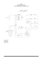
12 Volt Fuel System 8/01
13
14 23
28
6
7
8
1
5 12
2
3
4
10
3
16
11
22
21
20
29
25
24
19
17
18
30
31
NOER
27
24
15
26
notenoter
Ref. Part #
jgjgjjg
n
1
2
3
4*
5*
6
7
8
9
10
11
12
13
14
15
Description
60006A
50299A
170040
98668A
98838A
18124A
980657
98472A
Page 20
98858A
59620A
98703B
912226
693303
81102A
Switch Cover
Hose, 3/8" LP
Street Elbow
(W58) Lockoff, 12V. Fuel
(XA53-6) Nipple, 1/4 Hex
(XA53C) Regulator Asm. 12V
(H040) Washer, 1/4 Lock
Screw, Button, ¼-20 x 0.62
(MAC811) Tank, Polished Alum.
(XA58F) Coupler
Check Valve
(W6813) Switch, Ignition
Hour Meter
Hosebarb
Nut, Lock, ¼ -20
Clarke® Propane Burnishers Operator's Manual
27
Qty. Ref. Part # Description
1
1
2
(1)
(1)
1
2
2
1
1
1
1
1
1
2
16
16a
17
18
19
20
21
22
23*
24
25
26
27
28
29
30
31
40004A
40000A
98711A
98706A
98701A
98473A
98825A
98826A
98831A
87025A
85700A
98712A
98613A
98705A
69882A
42919A
43006A
14 HP Wiring Harness
17 HP Wiring Harness
(W6821) Battery, 12 Volt Non-spill
(W6815) Cable, Battery 11” Red
(W6811) Solenoid, 12 Volt
(H041) Clamp, 5/8 Wire Type
(XA50) Hose, 3/8 fuel
Vac Hose, 3/16
(XA53-ZZ) Elbow, 1/4 Street 90°
(H068) Washer, Flat
(H084) Screw, Hex, ¼ -20 x 1
(W6822) Box, Battery
Felt
Key
Bracket, Regulator
Fuse
Fuse Holder
Qty.
1
1
1
1
1
2
2 ft.
2 ft.
(1)
4
2
1
1
1
1
1
1
Page 19
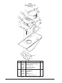
Clarke®
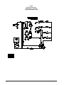
Vacuum Fuel System 7/03
14
(A, B, & C)
13
12
1
2
1
9
2
17
8
3
4
19
18
7
6
15
4
16
5
Ref. Part #
Description
Qty.
1
2
3
4
5
6
7
8
98472A
980657
Page 11
Page 11
Page 11
16619A
98844A
50299A
Screw, Button, ¼-20 x 0.62
(H040) Washer, Lock, ¼
Screw
Washer, Flat
Nut, Lock
Lockoff w/Fittings
(XA53AD) Hose, Assembly #3
Hose, 3/8" LP
4
4
4
8
4
1
1
1
9
18123A
Regulators Asm., Vacuum System
1
Page 20
Ref. Part #
Description
Qty.
12
14A
14B
14C
15
16
17
18
19
Carrier, Bottle
(MAC815) Tank, Aluminum, Polished
(MAC816) Tank, Steel, Painted
Tank, Aluminum, Pntd
Check Valve
Coupler, Propane
Hose Clamp
Hose, Vacuum
Tee
(Ref)
(1)
(1)
(1)
1
1
3
1
1
Page 11
98421A
98422A
98421B
59620A
98858A
722030
98826A
98666A
Clarke® Propane Burnishers Operator's Manual
Clarke®
Bearing Assembly Burnisher 2/00
w/o Jet Stream
1
2
3
7
4A
4C
4B
6
5
5a
6
7
vvvvvv
8
NOTE: 10643A
10644A
Kit, Bearing (4A,5,6,7) assembled
Kit, Bearing Jet-Stream (4B,5,6, & 7)
assembled
10683A Kit, Bearing, Onan 27" (4c, 5, 6 &7)
10130A Kit, Bearing, 1.5 Deg. (4a, 5a, 6 & 7)
Ref #
1
2
3
4A
4B
4C
5
5a
6
7
8A
8B
8C
8D
8E
8F
9
Part No.
98450A
98451A
980687
98567A
98570A
58328A
98657A
50934A
98660A
98460A
98581A
99033A
99033A
99059A
98565A
99059A
65305A
Description
Screw, Hex, 7/16-14 x 1.25
Washer, Lock, 7/16
Washer, Flat (H009)
Shaft, 21, 24 & 27 (W10H)
Shaft, Spray Buff (W10HSP)
Shaft, Onan 27"
Housing, Aluminum (W55HA)
Housing, 1.5 Taper
Bearing (W551)
Snap Ring, External (H022)
Pulley, 6” (w/o clutch) (W12A)
Pulley, 7.5” (w/clutch) (ZZZU13)
Pulley, 7.5" (w/o clutch)(ZZZU13)
Pulley, 10.0" (w/clutch)(ZZ14)
Pulley, 8.5” (w/o clutch) (W09)
Pulley, 10.0” (w/clutch) (ZZ14)
Key Shaft
Clarke® Propane Burnishers Operator's Manual
9
Qty. 21 24 27
4
x x x
4
x x x
4
x x x
(1) x x x
(1) x x x
(1)
x
1
x x x
1
x
2
x x x
2
x x x
(1) x
(1) x
(1)
x
(1)
x
(1)
x
(1)
x
1
x x x
Page 21
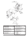
Clarke®
KAWASAKI Envirogard IV 7/03
13
14 9 6
8
7
1
12
33
4
3
5
34
10
11
2
31
30
22
16
18
35
32
28
27
26
29
17
25
36
24
19
37
38
15
Page 22
Clarke® Propane Burnishers Operator's Manual
Clarke®
KAWASAKI Envirogard IV 7/03
Ref #
1
2
3
4
5
6
7
8
9
10
11
12
13
14
15
16
17
18
19
20
21
22
24
25
26
27
28
29
30
31
32
33
34
35
36
37
38
NI
NI
Part No.
Page 19
Page 19
Page 19
Page 19
Page 19
Page 19
Page 19
Page 19
Page 19
Page 19
Page 19
Page 19
Page 19
Page 19
Page 19
40097A
Page 19
Page 19
Page 19
Page 19
Page 19
Page 19
60078A
98736A
40042A
98835A
30045A
98732A
98666A
50245A
40041A
40043A
80074A
98734A
42919A
43006A
Page 19
70139A
70137A
Description
Switch Cover
Hose Assembly
St. Elbow
Lockoff, Fuel 12V (W58)
Nipple (XA53-6)
Regulator Asm.
Washer, Lock, ¼
(Item #1) Screw
Hosebarb, 90 deg.
Coupler, Propane
Check Valve
Ignition Switch (W6813)
Hour Meter
Hosebarb
Nut
Harness, Envirogard IV
Battery (W6821)
Cable, Red
Starter Solenoid
Hose Clamp
Fuel Hose
Vacuum Hose
Solenoid Bracket
Brass Filter
Air Solenoid, 2-Port
Elbow, 90 deg. Hosebarb
Hose, 7/32
Air Solenoid 3-Port
Tee Hosebarb
Spud Asm.
Terminal, Piggyback
Module, Envirogard IV
Wave Washer
Sensor
Fuse
Fuse Holder
Battery Box
Engine Service Manual
Engine Parts Manual
Qty.
1
1
1
1
1
1
2
2
1
1
1
1
1
1
4
1
1
1
1
1
1
1
1
1
1
1
.16
1
1
1
2
1
1
1
1
1
1
1
1
Envirogard Replacement Engine (10022A)
These Components are supplied on the replacement engine
kit: manifold, gaskets, bonnet, fuel lines, vacuum lines and items
# 22, 24, 25, 26, 27, 28, 29, 31, 32 and 34. The catalytic convertor
and bracket are not included.
Clarke® Propane Burnishers Operator's Manual
Page 23
Clarke®
KAWASAKI Envirogard III 7/03
3
1
4
19
6
2
5
7
8
6a
17
9
10
6b
16
11
12
18
13
Page 24
14
15
Clarke® Propane Burnishers Operator's Manual
16
Clarke®
KAWASAKI Envirogard III 7/03
Ref #
1
2
3
4
5
6
6a
6b
7
8
9
10
11
12
13
14
15
16
17
18
19
Part No.
81102A
85806A
60222A
53639A
50364A
10048A
42919A
43006A
13715A
50362A
50367A
50363A
50371A
10361A
50372A
50373A
50369A
50376A
50375A
50370A
40093A
Description
Nut, Lock, ¼-20
Screw, Hex, ¼-20 x 0.75
Bracket
Elbow
Lockoff
Harness
Fuse
Fuse Holder
Envirogard III
Regulator
Hose
Carburator Kit
Nut, M8 x 1.0
Spud Kit
Elbow
Nipple
Injector
Elbow
Hose
Oxygen Sensor
Diode Asm.
Qty.
2
2
1
1
1
1
1
1
1
1
1
1
1
1
1
1
1
1
0.6
1
1
Engine Kit PN 10046A, without Catalytic Converter, includes items #
7, 10, 11, 12, 13, 14, 15, 16, 18 and from page 15 of this manual items # 3, 4, 11, 12, 13, 14, 15, 16, 17, 18, 19, 20, 21, 24, 26and 27.
Clarke® Propane Burnishers Operator's Manual
Page 25
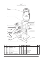
Clarke®
Pad Driver Assembly 11/05
1
2
3
11
4
12
5
6
4
7
(A,B,C)
2
8
9 (A, B, C)
10
1
8
8
NOTE:
indicates a
change has
been made
since the last
publication of
this manual.
* uses 3 for
center-lok pad
retainer to disk
and 8 for pad
gripper to disk
Page 26
Ref #
1
2
3
4
5
6
7A
7B
7C
8
9A
9B
9C
10
11
12
Part No.
920110
170860
98566A
98601A
98591A
98600A
98594A
98596A
98598A
56941A
98605A
50867A
50868A
98453A*
98453A
50935A
50936A
Description
Nut, Lock, 5/16 -18
Washer, Flat 5/16
Plate, Shaft (W10)
Bolt, Elevator (W18)
Coupler, Belting (W15)
Spacer, Coupling (W17)
Disk, Powder Coated 21” (W16-21P)
Disk, Powder Coated 24” (W16-24P)
Disk, Powder Coated 27” (W16-27P)
Centering Device
Pad Gripper Ring, 21" (W20)
Pad Gripper Ring, 24"
Pad Gripper Ring, 27"
Rivet, Pop Aluminum (H013)
Rivet, Pop Aluminum (H013)
Shaft Plate
Pad Driver, 21" Flex
Qty.
12
12
1
12
1
6
1
1
1
1
1
1
1
11
23
1
1
21"
24"
27"
21" Flex
Flex Pad Driver
Steel Pad Driver
x
x
x
x
x
x
x
x
x
x
x
x
x
x
x
x
x
x
x
x
x
x x x x
x
x
x
x
x x
x
x
Burnishing Pads
21" - 99931A
24" - 99945A
27" - 99953A
Pre-assembled steel
pad driver assemblies
includes items
1,2,3,4,5,6,7,8,9,10
21" - 17532A
24" - 17534A
27" - 17535A
Clarke® Propane Burnishers Operator's Manual
Belt Size
B38 B40
01A
990
98A
989
97A
989
96A
989
94A
989
3A
9899
2A
9899
91A
989
A
98990
A
98988
72
1916
8A
5103
7A
9898
76
1916
6A
9898
3A
5102
9898
4A
Belt Selection Chart
B41 B43 B44 B45 B46 B47 B49 B50 B51 B52 B53 B54 B55 B56 BB60
21 Std. Twin
21 Std. Single
21 w/Clutch
21 w/Battery
21 Strip
21" Combo
22 Standard
22 w/Clutch
22 Strip
24 Standard
24 w/Clutch
24 w/Battery
24 Strip
27 Standard
27 w/Battery
28 Strip
Strip/Buff
24 Onan
27 Onan
Clarke® Propane Burnishers Operator's Manual
Page 27
Clarke®
Pulley Chart 7/03
Engine Shaft
Part #
Description
1
2
3
3.5 x 1 Pulley (W11)
Electric Clutch (W14)
Centrifugal Clutch (W142) (2250)
98579A
98583A
98585A
Where Used
All Burnishers w/o clutch
All Burnishers w/electric clutch
All Burnishers w/centrifugal clutch (except Onan)
All Strippers
4 98588A
Double Centrifugal Clutch (W144)
All Strip/Buff Combinations
5A 98491A
Bolt
All machines except Strip/Buff combinations
5B 98474A
Bolt
All Strip/Buff Combinations
5C 50054A
Screw - KAW. 14 HP
With Clutch
5D 50031A
Screw - KAW. 17 HP
With Clutch
6* 98586A
Washer (W412)
All Clutches
7 98695A
Capacitor
All Electric Clutches
8 98476A
Spacer
With Clutch
9 51371A
Clutch, Centrifugal (1750)
Onan engines w/centrifugal clutch
10 98451A
Washer, Lock
All Burnishers w/ Clutch
*NOTE: Qty 7 of Item 6 used with centriugal clutch; Qty 6 of Item 6 used with electric clutch.
Front-End Shaft
Part #
Description
Where Used
98581A
99033A
98565A
99059A
99049A
98582A
191803
21 w/o clutch
21 w/clutch, 24 w/o clutch & 24, 27 Onan
27 w/o clutch
24 & 27 w/clutch
All Strippers
Strip/Buff Combinations
All Strip/Buff Pulleys
Pulley 6.0 x 1 (W12A)
Pulley 7.5 x 1 (ZZZU13)
Pulley 8.5 x 1 (W09)
Pulley 10.0 x 1 (ZZ14)
Pulley 12.0 x 1 (ZZ12)
Pulley 7.5 & 10.0 (W131)
Bushing (W13)
Clutch Variations
ELECTRIC
CENTRIFUGAL
8
2
4
3,9
6
5
Page 28
8
8
7
CENTRIFUGAL
DOUBLE GROOVE
6
5
6
5
Clarke® Propane Burnishers Operator's Manual
Clarke®
Electrical Schematic 120V A.C. System 2/00
Clarke® Propane Burnishers Operator's Manual
Page 29
Clarke®
KAWASAKI 14 HP Single
Electrical Schematic 12V D.C. System 5/99
Page 30
Clarke® Propane Burnishers Operator's Manual
Clarke®
KAWASAKI 14 HP Single
Electrical Schematic Enivorgard III 12V D.C. System 5/99
Clarke® Propane Burnishers Operator's Manual
Page 31
Clarke®
Electrical Schematic
KAWASAKI 17 HP TWIN
12 V. DC Fuel System 5/99
Page 32
Clarke® Propane Burnishers Operator's Manual
Clarke®
KAWASAKI 17 HP TWIN
Envirogard IV 12 Vdc System
Electrical Schematic 8/01
Clarke® Propane Burnishers Operator's Manual
Page 33
Clarke®
Onan P248 LP Engine 12V DC Fuel System
Electrical Schematic 6/98
Page 34
Clarke® Propane Burnishers Operator's Manual
CLARKE PRODUCT SUPPORT BRANCHES
U. S. A. Locations
CORPO
PRODUCTION FACILITIES
Clarke® , Springdale, Arkansas
2100 Highway 265
Springdale, Arkansas 72764
(479) 750-1000
Customer Service - 1-800-253-0367
Technical Service - 1-800-356-7274
American Lincoln®, Bowling Green, Ohio 43402
1100 Haskins Road
European Locations
PRODUCTION FACILITIES
ALTO Danmark A/S, Aalborg
Blytaekkervej 2
DK-9000 Aalborg
+45 72 18 21 00
ALTO Danmark A/S, Hadsund
Industrikvarteret
DK-9560 Hadsund
+45 72 18 21 00
SALES SUBSIDIARIES
SERVICE FACILITIES
Clarke®, Elk Grove, Illinois 60007
2280 Elmhurst Road
(847) 956-7900
ALTO US - Canada, Ontario (Canada)
4080 B Sladeview Crescent Unit 1
Mississauga, Ontario L5L 5Y5
(905) 569 0266
Clarke®, Denver, Colorado 80204
1955 West 13th Ave.
(303) 623-4367
ALTO Overseas Inc., Sydney (Australia)
1B/8 Resolution Drive
Caringbah NSW 2229
+61 2 9524 6122
Clarke®, Houston, Texas 77040
7215 North Gessner Road
713-937-7717
ALTO Cleaning Systems Asia Pte Ltd., Singapore
No. 17 Link Road
Singapore 619034
+65 268 1006
SERVICE AND SALES FACILITY
ALTO Deutschland GmbH, Bellenberg (Germany)
Guido-Oberdorfer-Straße 2-8
89287 Bellenberg
+49 0180 5 37 37 37
American Lincoln® / Clarke, Madison Heights,
Michigan 48071-0158
29815 John R.
(810) 544-6300
American Lincoln® / Clarke, Marietta, Georgia 30066
1455 Canton Road
(770) 973-5225
SALES AND DISTRIBUTION CENTER
Clarke®, Secaucus, NJ 07094
74 Henry Street
(201) 864-5503
Clarke®
Clarke American Sanders
A.L. Cook
Customer Service Headquarters and Factory
2100 Highway 265
Springdale, Arkansas 72764
(479) 750-1000
Technical Service
1-800-356-7274
ALTO Cleaning Systems (UK) Ltd., Penrith
Gilwilly Industrial Estate
Penrith
Cumbria CA11 9BN
+44 1768 868 995
ALTO France S.A. Strasbourg
B.P. 44, 4 Place d’Ostwald
F-67036 Strasbourg
Cedex 2
+33 3 8828 8400
ALTO Nederland B.V.
Postbus 65
3370 AB Hardinxveld-Giessendam
The Netherlands
+31 184 677 200
ALTO Sverige AB, Molndal (Sweden)
Aminogatan 18
Box 4029
S-431 04 Molndal
+46 31 706 73 00
ALTO Norge A/S, Oslo (Norway)
Bjornerudveien 24
N-1266
+47 2275 1770
Clarke® LIMITED U.S. WARRANTY
Clarke Industrial/Commercial Floor Product is warranted to be free from defects in workmanship under
normal use and service, when operated and maintained in accordance with Clarke's Maintenance and
Operations Instructions. The warranty period is from the date of purchase and is subject to the conditions
below.
2 YEARS FOR PARTS AND SERVICE LABOR (See exceptions below)
This warranty is extended only to the original purchaser for use of the product. Clarke will repair or replace,
at its option, any part that is proven to be defective in material or workmanship. Exceptions include electric
clutches and 110 volt starters which are warranted for a period of ninety (90) days only. Parts repaired or
replaced under this warranty are warranted only during the balance of the warranty period or ninety (90) days
thereafter, whichever is the greater. This warranty does not cover normal wear parts such as electrical cable,
rubber parts, and engine maintenance parts such as filters or spark plugs. This warranty covers the engine
components related to the LP fuel system. All other engine components are covered by the engine manufacturer.
This warranty does not cover paint or appearance items, misuse, neglect, or failure to maintain as
recommended by the manufacturer. The company disclaims any responsibility for loss of time, transportation,
commercial loss or other incidental or consequential damages.
BATTERY WARRANTY
The battery will be warranted by Clarke for a period of 6 months from the machine date of purchase. The
defective battery must be returned to Clarke. Returned batteries that are only in need of recharging will not be
warranted.
EMISSION CONTROL SYSTEM
In California the emission control system is warranted to the original owner and each subsequent owner for
a period of two (2) years from the date of delivery to the original owner.
STATED WARRANTIES ARE IN LIEU OF ALL OTHER WARRANTIES, EXPRESSED OR IMPLIED
Clarke's liability under this warranty is limited to repair of the product and /or replacement of parts and is given
to purchaser in lieu of all other remedies, including INCIDENTAL AND CONSEQUENTIAL DAMAGES.
THERE ARE NO EXPRESS WARRANTIES OTHER THAN THOSE SPECIFIED HEREIN. THERE ARE NO
WARRANTIES WHICH EXTEND BEYOND THE DESCRIPTION OF THE FACE HEREOF. NO WARRANTIES,
INCLUDING BUT NOT LIMITED TO WARRANTY OF MERCHANTABILITY, SHALL BE IMPLIED. A warranty
registration card is provided with your Clarke product. Return the card to assist Clarke in providing the
performance you expect from your new floor machine.
If difficulty develops with the product, you should:
a) Contact the nearest authorized Clarke repair location or contact the Clarke Service Operations
Department, 2100 Highway 265, Springdale Arkansas 72764, for the nearest authorized Clarke
repair location. Only these locations are authorized to make repairs to the product under this
warranty.
b) Return the product to the nearest Clarke repair location. Transportation and/or freight charges to
and from the repair location must be prepaid by the purchaser.
Clarke reserves the right to make changes or improvements to its machine without notice.
Always use genuine Clarke Parts for repair.
2100 Highway 265
Springdale, Arkansas, 72764