1
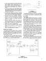
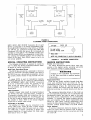
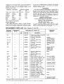
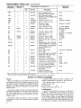
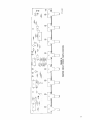
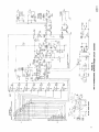
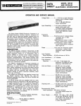
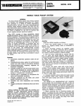
I
2 2 2 HARTREY AVE.. EVANSTON. IL. 6 0 2 0 4 U.S.A.
8
MICROPHONES AND ELECTRONIC COMPONENTS
A K t A I;uUt 3 1 Z I X b b . Z Z U U
I
TWX: 9 1 0 - 2 3 1 - 0 0 4 8
.
LAMLt:
I
1
I
bHuKtMILKU
MODEL SR110 A)qD
SRI 10-2E PROFESSIONAL
MONITOR MIXERS
.--
1 UW
A
SHEET
TELEX: 7 2 - 4 3 8 1
OPERATION AND SERVICE MANUAL
Number of lnput
Channels . . . . . . . . 8 mixed inputs; 1 program input
Power Output
DESCRIPTION
The Shure Model SR110 Professional Monitor Mixer
is a rack-mounted, eight-channel, line level mixer, designed as an accessory for the Shure Model SRlO1
Series 2 Audio Console or SR109 Professional Mixer.
It can also be used with similar equipment when a
separate stage monitor mixer is desired to be added
to a sound reinforcement system. The SR110 can also
be used in multi-track recording applications as a recording mix panel or in stereo broadcasting.
Interconnections between the SR110 and the SRlO1
or SR109 are made through a single multi-pin connector and cable permanently attached to the SRllO.
The SR110 also contains a matching female multi-pin
connector for "stacking" additional SRllOs.
The SR110 provides eight high-impedance, unbalanced, line level inputs to its mixing circuitry, and one
high-impedance, unbalanced line level input to its
output selector switch for monitoring program material. The output of the SR110 is a 600-ohm balanced
line level with one three-pin male professional audio
connector and two standard '/4 inch three-circuit
phone jacks, connected in parallel.
The front panel of the SRllO contains eight rotary
volume controls for channel gain, and a combination
rotary master volume controllpower-off switch. An
output selector slide switch, headphones jack and
neon power indicator lamp are provided. Silicon
transistors and other solid-state devices are used
throughout. All components are of the highest quality,
and are operated well within their respective ratings
to assure maximum reliability under normal use conditions.
The SR110 and SR110-2E are identical except that
the SRllO operates from 108-132 Vac, 50160 Hz, and
the SRllO-2E operates from either 105-125 or 210-250
Vac, 50160 Hz (switch-selectable).
SR110 Mixers are supplied with four rack-mounting
screws for mounting in standard 19 in. (483 mm) audio
equipment racks or in an optional Shure A105A Carrying Case (mounted with an SR109). In addition, the
SR110-2E is supplied with a detachable ac line cord
(without power plug). The SRl10 (only) is listed by
Underwriters' Laboratories, Inc., and is listed by
Canadian Standards Association as certified.
SPECIFICATIONS
. . . . . . . . . . . . . .All
Type
silicon transistor monitor
mixer
Copyright 1979, Shure Brothers Inc
27A1291 ( 5 6 )
. . . . . . +19.2
dBm (LINE LEVEL Output)
Voltage Gain*
Mixed
Inputs** . . . . . . .38 i 2 . 5 dB (LINE LEVEL Output)
14.5 t 2 . 5 dB (PHONES Output)
- 8 +-2 dB (MIX BUS)t
Program
Input** . . . . . . .40 +-2 dB (LINE LEVEL Output)
.
Frequency
Response
...
lnput Sensitivity
. i 3 dB, 20 Hz-20 kHz (LINE
. . . .21
LEVEL Output)
mV max. for + 4 dBm line
level output
+
12 dBm,
Distortion . . . . . . . . . .THD less than 1% at
30 Hz-20 kHz; IM distortion
less than 1% at +12 dBm
Noise
. - 68 dBV max. (MASTER
(300 HZ-20 kHz)
Volume Control down)
Mixed
Inputs** . . . . . . . -54 dBV max. (MASTER and
channel Volume Controls up)
Program
Input** . . . . . . . . -58 dBV max. (MASTER
Volume Control up)
Hum and Noise
(20 Hz-20 kHz) . . . - 64 dBV max. (MASTER
Volume Control down)
Mixed
Inputs** . . . . . . . -50 dBV max. (MASTER and
channel Volume Controls up)
Program
Input** . . . . . . . . -54 dBV max. (MASTER
Volume Control up)
lnput Clipping
Level at 1 kHz . . . .2.5V min. on mixed inputs 1-8
with channel Volume Controls
set at max. (input clipping
level increases with decreased
setting of channel Volume
Control)
lnput Impedance
at 1 kHz:
Mixed
Inputs** . . . . . . .23.5 kilohms
Program
Input** . . . . . . . .30 kilohms
*Measurement conditions: Inputs through 150 ohms, LINE LEVEL output
terminated in 600 ohms, PHONES output terminated in 8 ohms, MASTER
and channel Volume full up.
**OUTPUT SELECTOR Switch position.
+MIX BUS terminated in 5.6k.
Printed in
U.S.A.
I
I
FIGURE A.
SR110 FRONT PANEL
Output Impedances:
Line Level . . . . . ..Balanced 120 ohms actual (for
use with 600-ohm lines)
Headphone . . . . . .12 ohms actual (for use with 4to 16-ohm headphones)
Mix Bus . . . . . . . . .5.6 kilohms
Phasing . . . . . . . . . . .Pins 1 through 8 of ACCESSORY
connector are out of phase
with, and pin 9 is in phase
with, pin 3 of LlNE LEVEL output &pin connector, tips of
LINE LEVEL and PHONES
jacks, and tip of MIX BUS
phono pin jack
Volume: rotary, linear
taper; MASTER Volume:
rotary, audio taper
Operating Voltage . . . SR110: 108-132 Vac, 50/60 Hz.
SR110-2E: 105-125 or 210-250
Vac, 50/60 Hz.
Power
Consumption . . . . . 3 watts max. (Mixer only)
500 watts max. (non-switched
ac receptacle) (SR110 only)
Temperature:
Operating . . . . . . . . - 7 " to 54°C (+20° to 130°F)
Storage . . . . . . . . . -29" to 71°C (-20" to 160°F)
Dimensions . . . . . . . .44.4 mm height X 483 mm
width X 232 mm depth (13/4 in.
X 19 in. X 9% in.)
Weight . . . . . . . . . . . .3.9 kg (8 Ib, 8 oz)
Finish . . . . . . . . . . . . . Matte black
Installation . . . . . . . . .Equipped for standard 19 in.
(483 mm) audio rack mounting; may be operated in
o p t i o n a l - ~ 1 0 5Carrying
~'
Case
(with SR109)
Certifications . . . . . . .Listed by Underwriters' Laboratories, Inc.; listed by Canadian
Standards Association as
certified (SR110 only)
. . . . . . . . . . .Channel
Controls
OPERATING INSTRUCTIONS
Functional Description (Refer to Figures A and B)
1. Individual Channel Volume Rotary Controls (Eight)
-Control volume of each channel separately.
2. Power-On Indicator Lamp-Indicates
ac power is
being applied to unit.
-
4
3. MASTER Volume Rotary Control/POWER OFF
Switch-Adjusts
level of total monitor output and
applies ac power to power supply.
4. PHONES Output Jack-Provides
for connection of
stereo or monophonic headphones for monitoring.
5. OUTPUT SELECTOR Slide Switch-Selects
between signal mixed in SRllO (MIXED INPUTS) or
mixed in SRlO1 or SR109 (PROGRAM INPUT).
6. MONITOR OUTPUTS/LINE LEVEL Three-Circuit
Phone Jacks (Two)-Provide
balanced Monitor
Mixer output connection to power amplifier or
recording equipment.
7. MONITOR OUTPUTS/LINE LEVEL 3-Pin Male
Connector-Provides
balanced Monitor Mixer output connection to power amplifier or recording
equipment.
8. ACCESSORY INPUT AND OUTPUT Cable & MultiPin Male Connector-Provides
for input connections from Shure SR101 or SR109 or similar equipment.
9. ACCESSORY INPUT AND OUTPUT Multi-Pin Female Connector-Provides for connection of additional parallel-wired (tandem) S R l l 0s.
10. MIX BUS Phono Jack-Provides common mix bus
when two SRlOls or SRlO9s and two SRllOs are
to be operated in a common mix mode.
11. Ac Grounded Line Cord-Connects
ac power
source to SR110 power supply (SRllO only).
12. Non-Switched Ac Grounded Receptacle-Provides
up to 500 watts of non-switched ac power to accessory equipment (SR110 only).
13. AC (MAINS) POWER 3-Pin Connector-Connects
unit to ac (mains) power source via supplied line
cord (SR110-2E only).
14. VOLTAGE SELECTOR Slide Switch-Selects
105125V or 210-250V input power (SR110-2E only).
General Operating Instructions
WARNING
To reduce the risk of fire or electric shock,
do not expose this appliance to rain or extreme moisture.
1. Using hardware provided, install SR110 securely
in standard 19 in. (483 mm) rack or optional A105A
Carrying Case (with SR109) prior to making
electrical connections.
A C IMAINS! POWER
*'c,,X?,I
?..Ll.i..
.:,
/
13
,, 2 >>.> IL'
IT
w
" 1 $",*I
SR110-2E ONLY
\
14
FIGURE B.
SR110 REAR PANEL
-0.'
I,&
.*O
.dl
OL'?.,
1,1*
2. Connect SR110 MONITOR OUTPUTS/LINE LEVEL
3-pin connector and/or phone jacks (7, 6 ) to
power amplifier and/or recording equipment.
3. Connect SR110 ACCESSORY INPUT AND OUTPUT Multi-Pin Male Connector (8) to SRlOl or
SR109.
4. If additional SRllO is to be used (tandem operation), connect ACCESSORY INPUT AND OUTPUT
Multi-Pin Male Connector (8) of second SR110 to
ACCESSORY INPUT AND OUTPUT Female Connector (9) of first SR110.
5. If common mix between two SRlOls or SRlO9s
and two SRllOs is desired, interconnect MIX BUS
Phono Jacks (10) of each SR110 and interconnect
the link output jacks of the SRlOls or SRlO9s.
6. (SRl10-2E only) Move VOLTAGE SELECTOR
Switch (14) to 115V or 220V position as required.
7. Connect ac line cord to grounded 108- to 132-volt
(SRl1O), or 105-125V or 210-250V (SR110-2E),
50/60 Hz ac source.
8. Turn on front-panel POWER OFF Switch on
MASTER Volume Control (3). Red indicator lamp
(2) will light, indicating power is being applied.
9. Adjust SRlO1 or SR109 and associated power
amplifier for desired operating levels.
10. Adjust SRllO and associated power amplifier
and/or recording equipment for desired operating
levels.
11. Set OUTPUT SELECTOR Switch (5) to MIXED INPUTS or PROGRAM INPUT as desired.
4 4 . 4 m m ( 1 - 3 / 4 IN)
FIGURE C.
OVERALL DIMENSIONS
No special precautions are required for ventilation.
The SRl10 may be operated over a temperature range
of - 7 " to 54°C (20" to 130°F) in continuous duty without derating.
Mounting and Ventilation
The SRl10 Professional Monitor Mixer is designed
for rack-mounting in a standard 19 in. (483 mm) audio
equipment cabinet rack and is supplied with the necessary mounting hardware (see Figure C). If possible,
the SR110 should be rack-mounted above its associated SRl 01 or SR109.
Power Supply
The SR110 Professional Monitor Mixer is furnished
with a three-conductor power cable and three-prong
grounded plug (11). Connect the SR110 to an outlet
which supplies 108 to 132 volts ac, 50/60 Hz power.
The nominal power consumption at 120 volts under
normal operating conditions is 3 watts maximum (0.025
amperes at 120 volts). If extension cords are required
to supply power to the SR110, a high-quality, 18-gauge
or larger cord should be used.
The SRl10-2E is furnished with a three-conductor
line cord without a power plug. Obtain a suitable threepin male power plug and attach it to the line cord. The
plug should be installed by qualified service personnel.
(Brown lead goes to "hot" or "live" terminal, blue lead
to neutral terminal, and green/yellow lead to ground
or earth terminal.) Select proper operating voltage
(115V for 105-125V supply or 220V for 210-250V supply) using the VOLTAGE SELECTOR Switch (14).
A POWER-OFF Switch located on the front-panel
MASTER Volume Control (3) controls the application
of ac power to the SRl10, and a red indicator lamp
(2) indicates the power-on condition.
The SR110 may also be operated while mounted in
a Shure A105A Carrying Case. The A105A will accept
panel heights of 7 in. (178 mm), providing space for
one SRl10 and one SR109 Professional Mixer.
Functional Circuit Description
The inputs to the SRllO Professional Monitor Mixer
enter through the 11-pin male connector located on
the cable (8) (see Figure D). The 11-pin female con-
INPUT
AND OUTPUT
\
-----C-
i
I
CHANNEL
V O L U M E -MIX
/
DB
DB
MIX
RESISTOR
2
-
/'
MASTER
VOLUME
CONTROL
- 1 DB
OUTPUT
TRANSFORMER
/
-24 08
HEADPHONES
TRANSFORMER
FIGURE D.
SR110 BLOCK DIAGRAM
f
-
=
nector (9) is wired in parallel, and provides connection
for additional (tandem) SRllOs.
With the OUTPUT SELECTOR Switch (5) in the
MIXED INPUTS position, the input signals from the
individual channels of the SR101 or SR109 go through
the individual channel Volume Controls (I), a - 1 dB
mixing amplifier, a - 2 dB mixing resistor, and the
OUTPUT SELECTOR Switch before reaching the MASTER Volume Control (3). With the OUTPUT SELECTOR
Switch in the PROGRAM INPUT position, the program
input signal from the SR101 or SR109 goes directly
through the OUTPUT SELECTOR Switch to the MASTER Volume Control. The MIX BUS Jack (10) is connected after the mixing resistor and before the OUTPUT SELECTOR Switch. The MIX BUS Jack is for
parallel operation of two or more SR101 or SR1091
SRIIO combinations, providing 16 inputs with the OUTPUT SELECTOR Switch in the MIXED INPUTS position.
From the MASTER Volume Control (3), the signal
enters a +42 dB amplifier stage. The amplifier output
is fed to both line level ( - 1 dB) and headphone
(-24 dB) output transformers. The line level transformer feeds a three-pin professional male audio connector (7) and two standard 1/4" three-circuit (stereo)
phone jacks (6). The headphone transformer feeds a
standard Y4 in. three-circuit (stereo) phone jack (4)
designed for use with 8 ohm stereo or monophonic
headphones.
Inputs and Outputs
All SR110 inputs enter through the ACCESSORY INPUT AND OUTPUT 11-pin male connector (8). Pins 1
through 8 are the individual channel signals derived
from the eight SR101 or SR109 channels (following the
equalizer circuits), pin 9 is a total program signal
(taken from the SRlOl Monitor post link-pre link Switch
or SR109 link input jack), pin 10 is the SR101 or SR109
+30 Vdc supply voltage and is not internally connected to the SR110 supply, and pin 11 is ground.
The ACCESSORY INPUT AND OUTPUT 11-pin female connector (9) is wired in parallel with the male
connector, and provides for connection of additional
(tandem) S R l l 0s.
The MONITOR OUTPUTSILINE LEVEL connectors
consists of one three-pin professional male audio connector (7) and two standard VI in. three-circuit (stereo)
phone jacks (6). These connectors provide three line
level, 600-ohm, balanced outputs to power amplifiers
or recording equipment.
The MIX BUS Phono Jack (10) provides a common
connection when two SRlOls or SRIO9s and two or
more SRllOs are to be operated in a common mix
mode (16 channels). If more than two SRllOs are used
"Y" adapters can be used to connect the additional
MIX BUS Jacks.
The PHONES Jack (4) is a standard 1/4 in. threecircuit (stereo) phone jack designed for use with
8-ohm stereo or monophonic headphones.
TO
ACCESSORY
I
SRlOl
CONSOLE
SR109
OR
MIXER
T O STAGE
INPUT
I
/
I
4ii~
FIGURE E.
STAGE MONITOR CONNECTIONS
PUTS position and the MONITOR OUTPUTS connected
to the stage monitor power amplifier input, a separate
mix of inputs can be provided for stage monitoring.
The SRI10 monitors the SR101 or SR109 individual
channels after the SR101 or SR109 channel input attenuator, volume and equalizer controls.
With the OUTPUT SELECTOR Switch in the PROGRAM INPUT position the stage monitor has the same
mix as the SRlO1 or SR109. The program outputs of the
SR101 or Sf3109 are used for the "house" PA system.
Broadcast Line, House PA and Stage Monitor
If the SR101 or SR109 is to be used to feed a broadcast line for radio or TV audio, and separate house PA
and stage monitor systems are required, a number of
SRllOs may be connected as shown in Figure F. The
program output of the SR101 or SR109 feeds the
broadcast line, the monitor output of the first SR110
feeds a stage monitor power amplifier, and the monitor
output of the second (parallel-wired) SR110 feeds the
house system power amplifier. Note that since the
ACCESSORY INPUT AND OUTPUT Connectors (8, 9)
of the SR110 are in parallel, up to eight SRllOs may
be parallel-connected.
The individual channels that are not to be fed to the
stage monitor or house PA can be left off by turning
their Volume Controls (1) to 0 (off).
Stereo or Multi-Channel Tape Recording
A set-up similar to that described under Broadcast
Line above can be used to record a stereo tape or for
stereo broadcasting. The monitor output from one
SR110 is connected to one input of the tape recorder
and the other SR110 to the remaining input. This set-up
permits the user to select the desired mix on each
recording channel. For recording on more than two
channels, additional SRllOs can be added as desired.
16-Channel Mixer
For applications requiring the use of more than eight
channels, two SRlOls or SRlO9s can provide a 16channel mixing system by connecting their LINK OUTPUT Jacks. Monitoring of all 16 channels can be accomplished by connecting two SRllOs to the SRlOls
or SRlO9s as shown in Figure G. The male ACCES-
MONITOR
Stage Monitor
To use the SR110 as a stage monitor mixer (in conjunction with the SR101 or SR109), connect the ACCESSORY INPUT AND OUTPUT male connector (8) to
the SRlO1 or SR109 ACCESSORY OUTPUTIAUX LEVEL
female connector (see Figure E). Turn up the individual
channel Volume Controls (1) to be monitored on stage;
turn the remaining channel Volume Controls to 0 (off).
With the OUTPUT SELECTOR Switch in the MIXED IN-
OUT
FIGURE F.
BROADCAST LINE CONNECTIONS
TO STAGE
MONITOR
POWER
AMPLIFIER
ACCESSORY
INPUT
AND
OUTPUT
ACCESSORY
INPUT
AND
OUTPUT
FIGURE G.
16-CHANNEL MIXER CONNECTIONS
SORY INPUT AND OUTPUT Connector (8) of each
SR110 is connected to the female ACCESSORY OUTPUTIAUX LEVEL Connectors of the SRlOls or SRlO9s.
The SRllOs are connected through their MIX BUS
Connectors (10). With this set-up, all 16 channels are
available at each SRl10. The MASTER Volume Controls (3) of each SR110 are independent of each other,
and varying one MASTER Control will not affect the
output of the other. Each SRllO output is fed to its
own power amplifier.
I
TIP WlRE
3 6 0 0 5%
I
TO LlNE LEVEL
OUTPUT PHONE JACK
I O RING WlRE
0 i
I
I
NOTE: NO CONNECTION TO SLEEVE REQUIRED.
FIGURE H.
VU METER CONNECTION
SPECIAL OPERATING INSTRUCTIONS
SERVICE INSTRUCTIONS
The following information is supplied to enable the
user to utilize the SRl10 Professional Monitor Mixer
in special or custom installations.
Service (See Guarantee)
The SR110 Professional Monitor Mixer uses components of the highest quality, operating well within
their respective ratings to assure long life.
Multi-Track Recording Mixing
The S R l l O may be used as a submaster or mixdown
panel for multi-track recording systems. The input to
the SR110 can be a microphone preamplifier, recording console channel output or tape recorder line output.
A single SR110 is used for monophonic systems.
Additional SRllOs may be added by interconnecting
INPUT AND OUTPUT Connectors
the
(8, 9) for a multi-track system. For example, for an
eight inlfour out system, use four SRllOs. For a 16
Out 'ystem,
use
SR1lOs 'Onnected
in
mix
bused pairs.
Cable Extension
Should a longer cable length be required between
the SRllOs and their associated mixer, a length of
12-conductor, shielded cable and connectors may be
obtained from Shure Brothers Inc. (see Parts List). Up
to 12m (40 ft) may be added between the SRllOs and
the console or mixer. Refer to the Circuit Diagram
(Figure M) for proper cable wiring.
Connecting a VU Meter
An external VU meter may be connected to the
SR110 LlNE LEVEL output (6) with a series resistor
(see Figure H). Use a true VU meter (such as a Simpson 1349) and a resistor connected as shown. The
resistor should be a M-watt carbon, 5%. With a 600ohm load, 0 VU is + 4 dBm.
WARNING
Voltages in this equipment are hazardous
to life. Refer servicing to qualified service
personnel.
I
I
Replacement Parts
Parts that are readily available through local electronic parts distributors are not shown on the accompanying Parts List. Their values are shown on the
Circuit Diagram (Figure M). Commercial parts not
readily available and unique parts are shown on the
Parts List and may be ordered directly from the factory.
The commercial alternates shown on the Parts List
are not necessarily equivalents, but are electrically and
mechanically similar, and may be used in the event
that direct factory replacements are not immediately
available. To maintain the highest possible performance and reliability, Shure factory replacement parts
should be used. When ordering replacement parts,
specify the Shure Replacement Kit Number (RKC), description, product model number and serial number.
Cover Removal
To service components inside the chassis, the protective top cover must be removed. This is done by
removing eight screws from the top surface and lifting
the cover off.
FIGURE J.
SR110 TOP VIEW, COVER REMOVED
Fuse Replacement
The SRl10-2E (only) contains a 1/16A, Slo-Blo,
wired-in (pigtail) fuse which protects the power transformer. Be sure to replace this fuse only with one of
identical value and size.
Printed Circuit Board Removal
The SR110 chassis contains a printed circuit board
assembly (see Figure J). The foil side of the board
may be made accessible for servicing by disconnecting
leads K and L, and removing the eight knobs and
nuts securing individual channel Volume Controls R1
through R8 to the front panel. The board may be completely removed by unsoldering the 17 wires fastened
to the board. IMPORTANT: When disconnecting soldered board connections, make sure each wire is
identified for proper reconnection. This may be done
by affixing a piece of masking tape marked with the
connection or terminal letter to each wire.
Replace cover after servicing.
CIRCUIT BOARD WIRE COLORS
Letter
A
B
C
D
E
F
G
H
NOTE:
6
I
Wire Color
Brown
White/Red
Orange
Yellow
Green
Blue
Purple
G rav
II
Letter
I
Wire Color
Orange (2)
Bare
Bare (Shield)
Red
Black
Red
Red
Blue
Production variations may result in wire colors differing from those in the table.
Transistor and Diode Removal
All transistors and diodes used in the S R l l O are
mechanically supported by their leads. When replacing
these devices, proper lead configurations must be followed. Minimum soldering heat (preferably with a lowwattage soldering iron) should be used to avoid
damage to the device. Transistor lead codes are included in the Notes to Circuit Diagram (Figure L).
Transistor and Diode Checking
Defective transistors and diodes may be located by
use of a standard ohmmeter such as a Simpson 260.
Polarity of the ohmmeter must be verified before these
checks are made. Transistors and diodes must be
removed from the circuit before testing.
With a known diode orientation, measure the diode
resistance in the forward and reverse directions. The
lowest meter reading will establish the probe at the
cathode end (schematic symbol arrow points to cathode) as the "minus" probe while the other probe will
be "plus." Some ohmmeters are not polarized in this
manner with relation to "volts plus probe" and "volts
minus probe." With the ohmmeter "plus" probe on the
anode end of a diode, and the "minus" probe on the
cathode end, the ohmmeter should read approximately
2000 ohms or less. With the meter probes reversed, a
reading of about 10,000 ohms or more should be obtained. If either of these conditions is not met, the
diode should be replaced.
To check transistors, the ohmmeter should be set to
the 100- or 1,000-ohm scale. If all conditions in the
following table are met, the transistor may be con-
sidered free of any major defect; if any of the following
conditions are not met, the transistor should be replaced. See Notes to Circuit Diagram (Figure L) for
transistor lead codes.
Ohmmeter Connections
Ohmmeter
NPN
"Plus" Lead "Minus" Lead Transistor
Collector
Emitter
High
Emitter
Collector
High
Collector
Base
High
*
Emitter
Base
Base
Collector
Low
Base
Emitter
Low
Reading
PNP
Transistor
High
High
Low
Low
High
*Not a significant measurement.
Service Illustrations
The pages that follow contain a Parts Location
Drawing for the printed circuit board (Figure K) and an
overall Circuit Diagram (Figure M). Foil circuit paths
are shown as shaded areas in Figure K. The Circuit
Diagram shows all printed circuit board and chassismounted electrical parts.
GUARANTEE
This Shure product is guaranteed in normal use to
be free from electrical and mechanical defects for a
period of one year from date of purchase. Please
retain proof of purchase date. This guarantee includes
all parts and labor. This guarantee is in lieu of ariy
and all other guarantees or warranties, express or
implied, and there shall be no recovery for any consequential or incidental damages.
SHIPPING INSTRUCTIONS
Carefully repack the unit and return it prepaid to:
Shure Brothers Incorporated
Attention: Service Department
1501 West Shure Drive
Arlington Heights, Illinois 60004
If outside the United States, return the unit to your
dealer or Authorized Shure Service Center for repair.
The unit will be returned to you prepaid.
REPLACEMENT PARTS LIST (See Figures K and M)
Reference
Designation
Replacement
Kit No.*
I
Replacement Kit Consists Of:
Qty.
Commercial
Alternate
Description
Part No.
1
I
Printed Circuit Board Assembly
(with Potentiometers)
Capacitor, Electrolytic,
4 p,F, 25V
Capacitor, Electrolytic,
50 p,F, 35V
Capacitor, Electrolytic,
5 p,F, 35V
Capacitor, Electrolytic,
250 p,F, 40V
Capacitor, Electrolytic,
100 p,F, 25V
Capacitor, Electrolytic,
1000 ,uF, 40V
Capacitor, Electrolytic,
250 p,F, 40V
Silicon Rectifier, 50V, % A
Diode, Silicon, Computer, 75V
Silicon Rectifier, IOOV, % A
Fuse, Ac, Slo-Blo, Pigtail,
1116A (SRI 10-2E only)
Connector, Female, 1l - p i n
Connector, Phono Jack,
Grounded Shell
Connector, Phone Jack,
3-Conductor, Open Circuit
Connector, Male, 3-pin Audio
Connector, Phone Jack,
3-Conductor, Two Circuits
Connector, Female, NonSwitched Ac (SR110 only)
Connector, 3-Pin AC (MAINS)
POWER (SRllO-2E)
Ferrite Bead Ring
*Parts listed as RKC Kits should be ordered by that kit number.
Any orders received for piece parts where RKC Kit number is shown will be shipped in RKC quantities.
None
Mallory
TNT405U050POA
Sprague TE1307;
CDE NLW 50-50
Sprague TE1303;
CDE NLW 5-50
None
Sprague TE1211;
Mallory MTA
100F35; CDE
NLW 100-25
None
None
Motorola 1N4001
TI or GE IN4148
Motorola 1N4002
Littelfuse 3.5.062
Amphenol 126-805
Switchcraft 3511A
Switchcraft 128
Switchcraft C3M
Switchcraft 1128
None
None
Stackpole 57-0181;
Ferronics 21-031J
7
REPLACEMENT PARTS LIST-(Continued)
Reference
Designation
Replacement
Kit No.*
Replacement Kit Consists Of:
Commercial
Alternate
,
Qty.
Part No.
-
90F2085
Description
-
MPI
-
MP2
-
MP3
MP4
MP5
PI
PLI
Q1
-
-
90E2085
-
-
-
-
-
RKC9
4
44C211
90AP2600
30F481B
95A656
90E2600
86C349
1
86A336
86A348
-
1
1
-
86A334
86A335
46A053
R36lS2
-
-
46A054
R36lS2
-
-
46A073
S1
S2
S3
-
-
55C112
TI
T2
T3
T3
W1
-
W1
-
Q2
Q3
RKCI2
Q4
Q5
R1-R8
RKC65
RKC66
-
-
-
-
-
-
-
-
-
-
55A116
51 B229
51C228
51A253
51A259
95A632
90A1888
-
15A1202
Knob Assembly, Grey,
Individual Channel Volume
Knob Assembly, Black,
MASTER VolumeIPOWER OFF
Spring Shield
Connector Shell for P I
Screw, 4-40 x 7/16" (PI)
Connector, Male,
11-pin (less shell)
Lamp, Indicator, Neon
Transistor, Silicon, NPN
Transistor, Silicon, NPN
Transistor, Silicon, Low
Power, PNP
Transistor, Silicon, NPN
Transistor, Silicon, PNP
Potentiometer, 50K, Channel
Volume
Potentiometer, 50K, MASTER
Volume/POWER OFF (SRI 10)
Potentiometer, 50k, MASTER
VolumeIPOWER OFF
(SRI 10-2E)
Switch, Slide, DPDT
Part of R36
Switch, Slide, DPDT, VOLTAGE
SELECTOR (SRI 10-2E only)
Transformer, Output
Transformer, Headphones
Transformer, Power (SRI 10)
Transformer, Power (SRI 10-2E)
Line Cord and 3-Conductor
Ac Plug Assembly (SRI 10)
Line Cord and 3-Conductor Ac
Female Plug Assembly
(SRI 10-2E)
Cable, 12-Conductor
Shielded (specify length)
None
None
None
Amphenol 126-946
-
Amphenol 126-804
Leecraft 36N1311
Motorola 2N5088;
TI 2N3711
TI TIS97
Motorola or Fairchild
2N5087
TI TIS92
TI TIS93
None
None
None
Switchcraft 46206LSR
-
None
None
None
None
None
Belden 17408
None
None
*Parts listed as RKC Kits should be ordered by that kit number.
Any orders received for piece parts where RKC Kit number is shown w i l l be shipped in RKC quantities.
NOTES TO CIRCUIT DIAGRAM
General
Shure part numbers are not shown in the Parts List
accompanying the Circuit Diagram (Figure M) if parts
are readily available through local electronics parts
suppliers. In these instances, the Circuit Diagram
shows only the reference designation and value of the
standard parts.
All capacitor values are shown in microfarads unless
otherwise designated. All non-electrolytic capacitors
are 100 working volts dc or more unless otherwise
specified. Electrolytic capacitors are shown in microfarads X volts.
All resistor values are shown in ohms (k=1000).
Resistors are %-watt, 10% tolerance unless otherwise
specified.
Transistor lead codes are shown in Figure L. Acceptable r e p l a ~ e t n e n tare
~ shown in the Parts List.
The following ground symbols denote:
Chassis Ground /$7
Circuit Ground
Printed Circuit Board Ground
I-
6
Troubleshooting
A general troubleshooting process is as follows: If
the SRI10 is completely "dead," check the ac power
source and power supply output (34V at pin M of
printed circuit board). If the output is distorted, low
or not present, apply an input signal as described
under Ac Voltage Measurements below, and determine
that the input voltage to the board assembly is correct.
If an incorrect ac voltage is found on the board, per-
form Dc Voltage Measurements as described below to
isolate the problem area.
AC Voltage Measurements
The numbers within rectangular symbols
on
the Circuit Diagram denote the ac voltage at that point
under the following test conditions:
1. Voltage measured with respect to chassis unless
otherwise indicated.
2. Line voltage: 120V, 50160 Hz (SR110) or 115V
or 230V (SRl10-2E).
3. Test signal of 40 mV, 1000 Hz applied across
pin 1-8 (for desired channel) and ground pin 11
of ACCESSORY INPUT AND OUTPUT connector
PI.
4. Measurements made with ac VTVM of 1 megohm
or greater input impedance.
5. Load across LINE LEVEL OUTPUTS Connectors
J3-J5: 600 ohms total.
6. Ac voltage measurements may vary *30% from
values shown.
u
DC Voltage Measurements
The numbers within elliptical symbols o on the
Circuit Diagram denote the dc voltage at that point
under the following test conditions:
1. Voltage measured with respect to chassis unless
otherwise indicated.
2. Line voltage: 120V, 50160 Hz (SR110) or 115V
or 230V (SR110-2E).
3. No input signal applied.
4. Dc voltage measurements may vary t 2 0 % from
values shown.
5. Measurements made with VTVM of 11 megohms
or greater input impedance.
Resistance Measurements
With the ac line cord disconnected from the ac
source and the POWER-OFF Switch in the OFF position, the following ohmmeter measurements may be
made:
1. Transformers may be checked for continuity of
each winding.
2. To test transistors and diodes, see Transistor and
Diode Checking.
C
C
NOTE: ALTHOUGH OUTLINES MAY VARY, LEADS ARE
ALWAYS FORMED AS SHOWN ABOVE.
FIGURE L.
TRANSISTOR LEAD CODES
ARCHITECTS' AND ENGINEERS' SPECIFICATIONS*
The Monitor Mixer shall be a rack-mounted, 120-volt,
50/60 Hz line-operated all silicon transistor line level
mixer, designed for use with the Shure SR101 Series 2
Audio Console, SR109 Professional Mixer or similar
equipment which requires a stage monitor mixer separate from the program mixer. The Monitor Mixer can
also be used in multi-track recording applications as
a submaster mix panel or mixdown panel. Interconnections between the Monitor Mixer and SR101 or
SR109 shall be made through a single multi-pin connector permanently fastened to the Monitor Mixer. A
parallel-wired female connector shall provide for interconnection of additional Monitor Mixers.
The Monitor Mixer shall contain eight high-impedance, unbalanced, line level inputs to its mixing
circuitry, and one high-impedance, unbalanced, line
level input to its OUTPUT SELECTOR Switch for
monitoring program material. The Monitor Mixer outputs shall consist of one three-pin male professional
audio connector and two standard 1/4 inch three-circuit
phone jacks. Each shall be a line level, 600-ohm, balanced output. The Monitor Mixer shall contain a MIX
BUS phono connector for interconnecting Monitor
Mixers.
The Monitor Mixer output circuit balanced 600-ohm
A l l specifications apply to SRl10-2E except: operating voltage is 105-125
o r 210-250 volts; non-switched ac receptacle is not provided.
line shall have an output rated at + I 2 dBm at less
than 1% distortion with a minimum clipping level of
19.2 dBm. The Monitor Mixer shall have a voltage gain
of 40 1 2 dB (program input) and a maximum input
sensitivity of 21 mV for a $ 4 dBm program output.
The input channel clipping level at 1 kHz shall be
2.5V minimum and shall increase with channel settings
below 12.
The Monitor Mixer shall be enclosed in a metal,
rack-mounting enclosure housing with a scuff-resistant
vinyl-covered front panel. The dimensions shall be
44.5 mm in height, 483 mm in width, and 232 mm in
depth (1% in. x 19 in. x 9% in.). The weight shall not
be more than 3.9 kg (8 Ib, 8 02).
The front panel shall contain eight rotary individual
channel Volume Controls, one rotary MASTER Volume
ControllPOWER-OFF Switch, a power-on indicator
lamp, an OUTPUT SELECTOR Switch, and a PHONES
Jack. A non-switched ac receptacle rated -for 500 watts
maximum load shall be provided on the rear panel.
Any Monitor Mixer not meeting all of the above
specifications shall be deemed unacceptable under
this specification. The Monitor Mixer shall be a Shure
Model SR110.