1
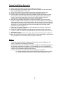
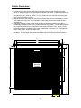
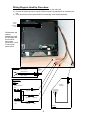
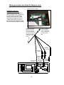
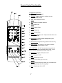
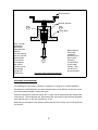
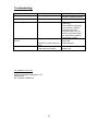
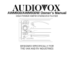
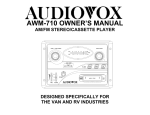
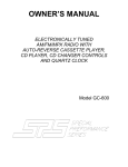
LCM1210FD
Owner’s/Installation
Manual
LCM1210 Flip-Down
In Vehicle
Entertainment System
Audiovox Specialized Applications, LLC
23319 Cooper Dr.
Elkhart, IN 46514
219-264-3135
Rear Panel Features:
1
3
2
4
5
6
1)
2)
3)
4)
Left RCA Out: Hook-up for the left audio out (white male RCA jack)
Right RCA Out: Hook-up for the right audio out (red male RCA jack)
Power Harness Connection: This plug connects to the power harness mating plug
Optional Headphone Connections: Green is right positive, Gray is left positive and Black is
the ground
5) Antenna Connections: This connects to the antenna if applicable.
6) DIN Connectors: The source component harness (P/N 8010730) connects here. A cable tie
will mount through holes provided in PCB, and is recommended for wire strain relief. A
second component harness is needed to utilize both mini-din connectors.
Front Button Panel Features:
1) Power: This button turns LCM1210FD on and off. Dimly lit when in stand-by mode
2) Channel ∆ ∇: Pressing ∆ will select channels higher and pressing ∇ will select channels
lower than current channel.
3) Volume ∆ ∇: Pressing ∆ will raise the volume and pressing ∇ will lower the volume.
4) Select: Each press of this button selects the next source (1-3). Note that some sources
produce an image, depending upon whether components are connected to all sources.
5) Latch: Sliding this latch forward will release the 12.1” monitor to drop into playing position.
6) AP: Places the tuner in auto-program mode. Auto program will scan all channels available
and store active channels into memory for easy selection with the channel up/down buttons.
7) Bright ∆ ∇: Pressing this button ∆ will increase monitor brightness, and pressing this button ∇
will decrease monitor brightness.
8) Contrast ∆ ∇: Pressing this button ∆ will increase picture contrast, and pressing this button ∇
will decrease contrast.
9) Color ∆ ∇: Pressing this button ∆ will increase color separation and pressing this button ∇ will
decrease color separation.
2
General Installation Approach:
1) Before beginning installation, please refer to warning on page 10.
2) Decide upon system configuration and options that will be installed (ie: what components,
VCP, remote headphones, 2nd VCP, etc).
3) Review all manuals to become familiar with electrical requirements and hook ups.
4) Decide upon mounting locations of all components and method of mounting.
5) Prep the vehicle by removing any interior trim necessary to gain access to vehicle power
hook up point as well as all areas where interconnecting wire harnesses will need to be
located. If any access holes need to be cut into the vehicle (headliner, other trim
components, etc.) this should be done now as well. Refer to page 4.
6) Route the wiring harnesses throughout the vehicle as necessary. (Refer to the wiring
diagram on pages 5 and 6 of this manual as well as the wiring instructions for the individual
components and accessory options being installed). Be sure that all wiring is protected from
sharp edges and is routed in such a manner that it will not be pinched when all components
and interior trim are fully installed. Be sure to leave enough slack in the wiring at each
component to allow working room.
7) Remove all A/V system components from their packaging and place them loosely in the
vehicle at their respective locations.
8) Connect all components together (electrically) and verify proper operation of all system
functions. NOTE: This is best done both BEFORE and AFTER all components have been
permanently mounted.
9) After verifying proper operation of the system, proceed with mounting of each component.
10) When all components are mounted, recheck function of entire system again to ensure that no
wiring was pinched or connected improperly during final installation.
Notes:
-
Connecting to both the Wireless Headphones IR Transmitter and an FM Modulator will
require an additional RCA Adapter (P/N 0892165).
One dual RCA Patch Cord is needed to connect the TV/Monitor to the Wireless Headphone
IR Transmitter. Available in two lengths: 3 Ft. (P/N 0892351) and 12 Ft. (P/N 0892353).
One dual RCA Patch Cord is needed to connect the TV/Monitor to the FM Modulator, and is
included in the FM Modulator package (P/N 0190730).
For audio output, there are a few scenarios that may apply to your system:
a) Remote headphone jacks may be added and located throughout the vehicle.
b) Additional speakers and amplifiers may be added throughout the vehicle.
3
Vehicle Preparation:
1) Locate vehicle power source. Generally this is best found near the vehicle’s fuse block,
which is usually (though not always) under the steering wheel area. Locate an accessory hot
circuit to tap into video system power. Accessory hot means a circuit that is +12VDC when
the ignition key is in either the “ACC’Y” or “Run” positions, and 0 volts DC when the ignition
key is removed from the vehicle.
2) Mounting location and method for the individual components will vary from vehicle to vehicle.
This manual will only focus on the installation of the video pod itself and related console
accessories.
3) Generally, the best location for the video pod itself is where the vehicle’s dome light is
traditionally installed (center of roof, just behind the two front seats). The pod should NEVER
be located in a position that would place it within the driver’s field of view. This is not only
hazardous for driving conditions (as it creates a distraction to the driver), but it is against the
law in many states. Check your state laws.
4) Once the pod location has been determined, there may be prep work required for the
headliner. See mounting detail below for headliner cutout dimensions and hole locations.
12.55
11.50
10.65
0.43
0.53
0.75
0.53
Hinge side
2.21
LCM1210FD
Mounting
Template
10.00
6.04
12.31
11.25
1.25
2.00
4
Wiring Diagram Hook Up Procedure:
1) Connect the power harness to the mating connector on the video pod.
2) Connect the power harness to vehicle’s electrical system by tapping into an accessory hot
line.
3) Verify all functions of the system before final mounting of the finished assembly.
Left Out
(White)
Right Out
(Red)
FM Modulator and
wireless
headphones could
be connected with
two dual RCA
patch cords,
connected to L and
R output jacks
shown above.
Power Harness
Item C1
Power
Connector
(2-pin)
Red: +12 VDC
(Accessory Cir.)
Black: Ground
Optional Remote
Headphone
Stations
Antenna
Connector
Stereo Headphone
Jack
Spade
Terminals
Stereo Headphone
Jack
TV antenna
(If applicable)
Green
(Right+)
Spade
Terminals
Black
(Ground)
Spade
Terminals
Gray
(Left+)
Antenna
5
Wiring procedure and Hook Up Diagram cont.:
Mini-Din Connection Detail
FM Modulator/Wireless
Headphone Connections
FM Modulator white RCA jacks to
Red RCA (Right Audio Out) and Red
or Yellow RCA from Modulator to
Red RCA (Left Audio Out). WHS100 Wireless Headphones Red or
Yellow to White RCA (Left Audio
Out) and Wireless Headphone White
RCA to White RCA (Right Audio Out)
IR LED: Clean the IR
Receiver window on
the front of the VCP,
remove the adhesive
backing and apply the
IR LED to IR window
on the face of the
VCP.
Connect to Mini-Din
Connector in area
shown. A Cable Tie
may be used in holes
provided for strain
relief
Red RCA
R- Audio In
White RCA
L- Audio In
Audio "Y"
Adapter
Power (4-Pin)
Connector
6
For Use w/
Non-Stereo
Installations
Yellow
RCA
Video In
Remote Control Functionality:
TELEVISION CONTROLS:
1) TV Power: Turns unit on/off
2) TV/Video: Toggles between 3 available sources;
Tuner/VCP/DVD (VCP2)
3) Mute: Mutes headphone audio
4) 0-9: Numbers for channel selection
5) ∆ CH: Channel Up
6) ∇ CH: Channel Down
7) ∆ Vol: Volume Up
8) ∇ Vol: Volume Down
9) Skip/Search: Toggles on/off. Skips channels that are not
auto-programmed
10) Write/Erase: Controls manual adding/deleting autoprogrammed channels
11) Auto-Memory: Programs stronger stations into memory
12) Picture Select: This function is not active on remote.
User must adjust with controls on unit.
VCP CONTROLS: If a VCP is connected to source 2 or 3,
these buttons will control functionality of the VCP. The IR
emitter must be connected to the front of the VCP.
13) VCP Power: Toggles VCP power on/off
14) Play: Play tape in VCP
15) REW: Rewind tape in VCP
16) FFWD: Fast forward tape in the VCP
17) Pause: this button will stop current play, rewind the tape
and replay the tape from the beginning
18) Stop: Stop the tape in the VCP.
7
Roof Structure
Optional Spacers
C4
C5
Screw Boss
Note, If longer
screws are
substituted,
care should be
taken to
prevent piercing
the roof, and be
sure that pan
head screws
and washers
are used to
prevent screws
from pulling
though the
screw boss.
Nylon spacers
have been
supplied in
accessory kit to
place under
mounting
screws and/or
under screw
bosses. They
can be cut to
size as needed.
C3
Cut-Away View of Mounting Bosses
Antenna Information:
The following are a few points to consider in regards to TV reception in a mobile application.
Generally in a mobile application, the lower channels are the most difficult to receive due to the
size of the antenna needed to receive the signal.
When the antennas are inside the vehicle, the TV signal can be obstructed by the outside metal
of the vehicle. This will diminish UHF performance and may eliminate VHF reception altogether.
VHF channels are 2-13 and UHF channels are 14-69.
Depending on the location of the antenna and the direction of the vehicle, some VHF signal may
be received.
8
Troubleshooting:
Symptom:
Picture scrolls or is fuzzy
Cause:
Antenna type or location
Poor Reception
Vehicle is moving
Not receiving certain channels
Connections
Unit will not respond to remote
control
Sensor is blocked
No power to unit
Batteries in remote control are
weak
Power connection
Fuse blown at fuse panel
For Installation Help, Call:
Audiovox Specialized Applications, LLC
800-688-3135
M-F, 8:00AM –5:00PM CST
9
Possible Solution:
Change antenna or try
antenna in a different location
Vehicle may be outside of TV
signal range.
Check antenna connections.
Check number of antenna
connections- the more
connections there are, the
greater the chance of signal
loss, reduce the number of
connectons if possible.
Clear path for sensors or clean
sensor lens.
Replace batteries
Check connections
Replace fuse
Specifications:
Video System:
A/V Switching:
Power:
Aux Audio Outputs:
Current Consumption (stand-by mode):
Current Consumption (on, but no VCP):
Current Consumption (with one VCP on):
Audio Noise Floor (30KHz BW):
THD+N @ -10dBV, 1KHz (30KHz BW):
Crosstalk @ 1KHz:
Maximum Input Level, Audio L and R:
Frequency Response, 20Hz – 20KHz:
Frequency Response, 40Hz – 16KHz:
Channel Balance:
Volume Control:
Unit Weight:
NSTC Analog Composite Video (1V P-P, 75Ω)
3 channels
10-16 VDC, Negative Ground
Left and Right Variable (800mV max, 8Ω load min.)
Left and Right Fixed (300mV typical, 600Ω load min.)
67mA
635mA
1.5A
1.164mV (-58dB re:1V)
0.356%
60dB
800mV
±1.5dB
±0.5dB
±0.5dB, 0.05dB Typical
Dual 64 position log taper w/true 1dB/step accuracy
4.5 lbs.
Warning:
It is unlawful in most jurisdictions for a person to drive a motor vehicle which is equipped with a
television viewer or screen that is located in the motor vehicle at any point forward of the back of
the driver’s seat, or that is visible directly or indirectly, to the driver while operating the vehicle.
This product should only be installed to the rear of the back of the driver’s seat where it will not be
visible, directly or indirectly, to the operator of the motor vehicle.
10
Accessory List
Description
AVT-988 9” Color Television with Remote (12V)
AVT-597 5” Color Television with Remote (12V)
AVT-1498 13” Color Television with Remote (12V)
AVP-7000 Video Cassette Player (12V)
AVP-7285 Video Cassette Player (12V)
Wireless Headphone Kit: Includes 2 sets Wireless Headphones and Transmitter
BPA-501-12 4 Amp Adapter for use with AVT-988 9” and AVT-1498 13” Televisions
AC2A- 2 Amp Adapter for use with AVT-597 5” TV and AVP-7000 Video Cassette
Player
Unified Remote Control
VAC-21- 12 Volt Corded Vacuum
AVF-1 12 Volt Rechargeable Flashlight
HP-175 Headphones with Pivoting Ear Cup
HP-275 Headphones with Volume Control on Cord
HP-375 Studio Quality Headphones
Part Number
AVT988
AVT597
AVT1498
AVP7000
AVP7285
WRFKIT1
0891412
0891436
0892325
VAC21
AVF1
HP175
HP275
HP375
Unlike household electronics, all of our products have been specifically designed and tested for
the mobile environment and are only available through ASA. To order any of these products,
please contact Audiovox Specialized Applications at www.asaelectronics.com or 800-688-3135.
P/N 8011300
Rev.C 12/00