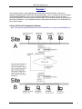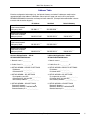
1
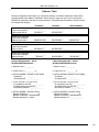
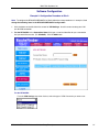
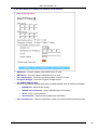
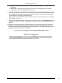
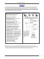
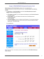
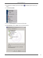
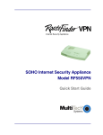
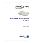
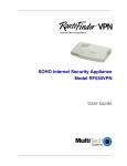
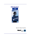
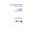
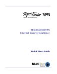
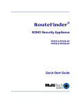
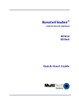
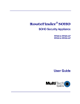
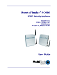
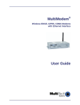
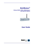
RF550VPN and RF560VPN
Setup Examples
Reference Guide
Multi-Tech Systems, Inc.
How-To: RF550VPN/RF560VPN Application
Examples
Copyright © 2003
This publication may not be reproduced, in whole or in part, without prior expressed written permission
from Multi-Tech Systems, Inc. All rights reserved. Multi-Tech Systems, Inc. makes no representations or
warranty with respect to the contents hereof and specifically disclaims any implied warranties of
merchantability or fitness for any particular purpose. Furthermore, Multi-Tech Systems, Inc. reserves the
right to revise this publication and to make changes from time to time in the content hereof without
obligation of Multi-Tech Systems, Inc. to notify any person or organization of such revisions or changes.
Product Number: S000258D
Revision
Date
Description
A
B
B1
04/09/02
04/17/02
04/26/02
B2
05/06/02
B3
B4
05/20/02
06/27/02
B5
C
D
07/18/02
04/18/03
07/07/03
Initial release
Added example 3
Minor changes to configuration tables.
Update Screen shots for Sentinel production version 1.3.
Added Manual choice for Secure Association under VPN Settings.
Added notes stating that Secure Association set for Manual only works for static to
static connection.
Clarified Sentinel procedure and removed Dynamic IP option.
Updated screen shots for RF550VPN/RF560VPN firmware V4.62. Corrections to
example 2 using Dynamic IP.
Added Dynamic IP back into example 4.
Changes to suppport software version 4.64
Add RF560VPN.
Contents
1. A LAN-to-LAN VPN configuration between Two RF550VPN/RF560VPNs. One at Site A and one
at Site B. Both RouteFinders using static IP addresses at their WAN port gateways.
2. A LAN-to-LAN VPN configuration between an RF550VPN/RF560VPN at Site A using a static IP
address and an RF550VPN/RF560VPN at Site B using dynamic IP addressing through their
respective WAN ports.
3. A LAN-to-LAN VPN configuration between an RF550VPN/RF560VPN at Site A using a static IP
address at the WAN port and an RF550VPN/RF560VPN at Site B using dynamic IP addressing
through a modem connected to the serial port.
4. A Client-to-LAN configuration between an RF550VPN/RF560VPN at Site A with a SSH Sentinel
Client.
The RouteFinder software is pre-installed on the RF550VPN/RF560VPN RouteFinder. Initial
configuration is required in order for you to run the RouteFinder software and begin operation. The
browser-based interface eases VPN configuration and management. The VPN functionality is based on
IPSec and PPTP protocols and uses 168-bit Triple DES encryption to ensure that your information
remains private.
Caution: Use a safe Password! Your first name spelled backwards is not a sufficiently safe password; a
password such as xfT35$4 is better.
RF550VPN/RF560VPN Reference Guide – Setup Examples
2
Multi-Tech Systems, Inc.
Example 1
This example provides a sample RouteFinder configuration and related address scheme for an
application employing LAN-to-LAN IPSec VPN communication. This is an example on how to configure
an RF550VPN/RF560VPN at Site A and an RF550VPN/RF560VPN at Site B so Site A and B can
communicate through a secure connection over the Internet. This example assumes both VPN gateways
have fixed IP addresses. This example does explain setting Secure Association in the VPN Settings as
IKE or Manual mode.
LAN-to-LAN Fixed IP Configuration Diagram:
Note: The illustration labels the RouteFinder as the RF550VPN, but it stands for the RF560VPN also.
RF550VPN/RF560VPN Reference Guide – Setup Examples
3
Multi-Tech Systems, Inc.
Example 1: LAN-to-LAN Configuration Chart
LAN-to-LAN Application – Site A:
RF550VPN/RF560VPN-Static
LAN-to-LAN Application – Site B:
RF550VPN/RF560VPN-Static
1. Domain name = Site-A.com
1. Domain name = Site-B.com
2. Public Class C = 204.26.122.x
2. Public Class C = 204.26.122.x
3. SETUP WIZARD > DEVICE IP SETTINGS
IP Address: 192.168.2.1
IP Subnet Mask: 255.255.255.0
3. SETUP WIZARD > DEVICE IP SETTINGS
IP Address: 192.168.10.1
IP Subnet Mask: 255.255.255.0
4. SETUP WIZARD > ISP SETTINGS
Select ‘Static IP Settings
IP assigned by your ISP: 204.26.122.103
IP Subnet Mask: 255.255.255.0
ISP Gateway Address: 204.26.122.3
4. SETUP WIZARD > ISP SETTINGS
Select ‘Static IP Settings
IP assigned by your ISP: 204.26.122.3
IP Subnet Mask: 255.255.255.0
ISP Gateway Address: 204.26.122.103
5. SETUP WIZARD > VPN SETTINGS
Connection Name = SiteAtoB
Disable (do not check) ‘Enable UID’
Disable (do not check) ‘Keep Alive’
Disable (do not check) ‘NetBIOS Broadcast’
Remote Site = LAN
Remote IP Network = 192.168.10.0
Remote IP Netmask = 255.255.255.0
Remote Gateway IP = 204.26.122.3
Network Interface = WAN ETHERNET
Secure Association = check IKE
Perfect Forward Secure = check enabled
Encryption Protocol = select 3DES
Preshared Key = (must match key code at Site B)
Key Life = set to default
IKE Life Time = set to default
5. SETUP WIZARD > VPN SETTINGS
Connection Name = SiteBtoA
Disable (do not check) ‘Enable UID’
Disable (do not check) ‘Keep Alive’
Disable (do not check) ‘NetBIOS Broadcast’
Remote Site = LAN
Remote IP Network = 192.168.2.0
Remote IP Netmask = 255.255.255.0
Remote Gateway IP = 204.26.122.103
Network Interface = WAN ETHERNET
Secure Association = check IKE
Perfect Forward Secure = check enabled
Encryption Protocol = select 3DES
Preshared Key = (must match key code at Site A)
Key Life = set to default
IKE Life Time = set to default
RF550VPN/RF560VPN Reference Guide – Setup Examples
4
Multi-Tech Systems, Inc.
Address Table
Enter the configuration information (e.g., the Default Gateway and other IP addresses used) into the
appropriate field of the Address Table below. Please print this page and use it to fill in your specific
RF550VPN/RF560VPN information and keep for future reference. (Example information below is shown
to match with the earlier diagram.)
IP Address
Net Mask
Network Port connected
to the internal network
(LAN ports) Site A
___.___.___.___
192.168.2.1
___.___.___.___
255.255.255.0
Network Port connected
to the external network
(WAN port) Site A
___.___.___.___
204.26.122.103
___.___.___.___
255.255.255.0
Network Port connected
to the internal network
(LAN ports) Site B
___.___.___.___
192.168.10.1
___.___.___.___
255.255.255.0
Network Port connected
to the external network
(WAN port) Site B
___.___.___.___
204.26.122.3
___.___.___.___
255.255.255.0
Default Gateway
___.___.___.___
204.26.122.1
___.___.___.___
204.26.122.1
LAN-to-LAN Application – Site A:
RF550VPN/RF560VPN-Static
LAN-to-LAN Application – Site B:
RF550VPN/RF560VPN-Static
1. Domain name = __________
1. Domain name = __________
2. Public Class C = ___.___.___.X
2. Public Class C = ___.___.___.X
3. SETUP WIZARD > DEVICE IP SETTINGS
IP Address: ___.___.___.___
IP Subnet Mask: ___.___.___.___
3. SETUP WIZARD > DEVICE IP SETTINGS
IP Address: ___.___.___.___
IP Subnet Mask: ___.___.___.___
4. SETUP WIZARD > ISP SETTINGS
IP assigned by your ISP: ___.___.___.___
IP Subnet Mask: 255.255.255.___
ISP Gateway Address: ___.___.___.___
4. SETUP WIZARD > ISP SETTINGS
IP assigned by your ISP: ___.___.___.___
IP Subnet Mask: 255.255.255.___
ISP Gateway Address: ___.___.___.___
5. SETUP WIZARD > VPN SETTINGS
Remote IP Network = ___.___.___.0
Remote IP Netmask = 255.255.255.0
Remote Gateway IP = ___.___.___.___
5. SETUP WIZARD > VPN SETTINGS
Remote IP Network = ___.___.___.0
Remote IP Netmask = 255.255.255.0
Remote Gateway IP = ___.___.___.___
RF550VPN/RF560VPN Reference Guide – Setup Examples
5
Multi-Tech Systems, Inc.
Software Configuration
Example 1: Configuration Procedure at Site A
1. Connect a workstation to one of the RF550VPN/RF560VPN’s LAN ports via Ethernet at Site A.
2. Set the workstation IP address to 192.168.2.x subnet.
3. Apply power to the RF550VPN/RF560VPN RouteFinder and allow the LEDs to stabilize on the unit.
4. Bring up your web browser on the workstation. At the Web browser’s address line, type the Gateway
address http://192.168.2.1 and press the Enter key.
Note: Make sure your workstation’s IP address is in the same network as the router’s address.
WINIPCFG and IPCONFIG are tools for finding a computer’s default gateway and MAC address. In
Windows 98/Me you can type WINIPCFG. In Windows 2000/NT, you can type IPCONFIG.
5. After typing the IP Address in the Web browser, the RF550VPN/RF560VPN main menu displays.
RF550VPN/RF560VPN Reference Guide – Setup Examples
6
Multi-Tech Systems, Inc.
6. On the Main Menu, click the Setup Wizard button. The Password dialog box displays.
7. Type admin (admin is the default user name) in the user name box and leave the password box
empty.
Note: To change your password after logging in, select the Advanced Settings button and
Administrative Settings.
8. Click OK. The Setup Wizard screen displays a step-by-step process that lets you input all of the
basic settings to configure your RF550VPN/RF560VPN.
9. Select the Time Zone, and then click the Next button to continue.
RF550VPN/RF560VPN Reference Guide – Setup Examples
7
Multi-Tech Systems, Inc.
10. For Device IP Settings enter the internal LAN IP address and subnet mask that you want assigned
to the LAN ports of the RF550VPN/RF560VPN. This is not the IP address from your ISP but the local
internal LAN IP address. The default IP address is 192.168.2.1 and will be used for our example.
Device IP Address: 192.168.2.1.
Device IP Subnet Mask: 255.255.255.0
Click the Next button.
RF550VPN/RF560VPN Reference Guide – Setup Examples
8
Multi-Tech Systems, Inc.
11. For ISP Settings, select Static IP Settings and enter the following information.
a)
IP Assigned by your ISP: This is the IP address of the WAN port on the RF550VPN/RF560VPN
at Site A.
(Ex: 204.26.122.103)
b)
IP Subnet Mask: This is the IP address of the subnet mask for the WAN port on the
RF550VPN/RF560VPN.
(Ex: 255.255.255.0)
c)
IP Gateway Address: This is the IP address of the WAN port on the RF550VPN/RF560VPN at
Site B.
(Ex: 204.26.122.3)
Click the Next button.
Note: For this scenario of connecting two RouteFinders back-to-back it is not necessary to enter any
information for the ISP Additional Settings or Modem Settings.
RF550VPN/RF560VPN Reference Guide – Setup Examples
9
Multi-Tech Systems, Inc.
12. Click the button on the left side of the screen for VPN Settings. Use this screen to setup your LANto-LAN VPN connection.
13. For the RF550VPN: In the Connection Name field, type a name that identifies for you a connection
that you would like to make. (Ex: SiteAtoB). Click the Add button.
For the RF560VPN:
From the VPN Settings drop-down list box, select the type of VPN Connection you want to set:
RF550VPN/RF560VPN Reference Guide – Setup Examples
10
Multi-Tech Systems, Inc.
If you select Setup IPSEC Settings, the following screen displays:
· In the Connection Name field, type a name that describes a connection you would like to make.
· Example: Site A.
· Click the Add button, and the VPN Settings detail screen will display (see the next screen). Once
you have entered the settings, the Connection Name displays on the lower half of the screen
(above).
· Click the checkbox if you want to Disable Internet Access (VPN Tunnel Only).
· You can then edit, delete, or enable/disable this connection by clicking the corresponding buttons.
· To enable this connection, check the Enable box.
Note: If you uncheck the Enable box, the connection will not be active, but the parameters will
remain on the screen for you to enable, edit, or delete as desired.
RF550VPN/RF560VPN Reference Guide – Setup Examples
11
Multi-Tech Systems, Inc.
If you select Setup PPTP Settings, the following screen displays:
·
DNS Server – Enter the address of the DNS Server to be used.
·
WINS Server – Enter the address of WINS Server to be used.
·
User Authentication – Select the User Authentication method to be used.
·
Encryption Strength – Select the Encryption Strength desired.
·
Use RADIUS Authentication:
Check the Use RADIUS Authentication button to enable RADIUS. Then the following information:
▪
▪
▪
▪
·
RADIUS Port – Select the port number.
RADIUS Server IP Address – Enter the RADIUS Server IP Address.
Secret – Enter a secret password.
Secret Confirm – Retype the secret password for verification.
Use Local Client List – Check this radio button to have your local client list used by the program.
RF550VPN/RF560VPN Reference Guide – Setup Examples
12
Multi-Tech Systems, Inc.
14a. The VPN Settings screen for entering specific VPN settings will display. The screen pictured
below assumes IKE is selected as the Secure Association. The Connection Name (SiteAtoB)
defaults into the first field. Two configuration choices are available for the Secure Association: IKE
and Manual.
a)
b)
c)
d)
Select Disable UID and leave Local IPSec Identifier and Remote IPSec Identifier blank.
Do not check Enabled Keep Alive.
Do not check Enabled NetBIOS Broadcast.
Remote Site – Select LAN.
e) Remote IP Network – Enter the Remote IP Network address (LAN) for Site B.
f) (Ex: 192.168.10.0)
g) Remote IP Netmask – Enter the Remote IP Netmask address for Site B. (Ex:
255.255.255.0)
h) Remote Gateway IP – Enter the Remote Gateway IP address (WAN) for Site B.
i) (Ex: 204.26.122.3)
Network Interface – Select the Network Interface from the drop-down list box. (Ex: WAN
Ethernet)
k) Secure Association – Select IKE to set how inbound packets will be filtered. IKE is the
default. IKE primarily encompasses router key exchange and the negotiation of security
policy. Selecting IKE will display the following fields.
l) Perfect Forward Secure – Check the Enabled button.
j)
RF550VPN/RF560VPN Reference Guide – Setup Examples
13
Multi-Tech Systems, Inc.
m) Encryption Protocol – Select the encryption protocol used for your configuration. The
default protocol for the RF550VPN/RF560VPN communicating with another
RF550VPN/RF560VPN is 3DES. (Ex: 3DES)
n) PreShared Key – Enter the PreShared Key name (you can enter an alphanumeric name but
it needs to match the security code for the RouteFinder at Site B).
o) Key Life – Enter the amount of time that tells the router to renegotiate the Key. For example,
3600 seconds is 60 minutes.
p) IKE Life Time – Enter the amount of time that tells the router to renegotiate the IKE security
association. For example, 28800 seconds is 8 hours.
14b. The screen pictured below assumes Manual as the Secure Association is selected on the VPN
Settings screen. The Connection Name (SiteAtoB) defaults into the first field. Continue to enter
the following settings:
Note: If Secure Association is set to Manual, the two RF550VPN/RF560VPNs must
communicate with Static IP addresses at both ends.
Note: Enter all data for a) through h) as illustrated above. Then complete the following:
i) Secure Association – Selecting Manual instead of IKE will set how inbound packets will be
filtered and then the following fields display.
j)
k)
l)
m)
n)
o)
Incoming SPI – Enter the incoming SPI that the remote VPN gateway, at Site B, will use to
identify this Security Association. Enter a three-digit number between 100 and 400. This value
must match the outgoing SPI value entered at the remote VPN gateway at Site B. (Ex: 400)
Outgoing SPI – Enter the outgoing SPI that the Site A VPN gateway will use to identify this
Security Association. Enter a three-digit number between 100 and 400. This value must match
the incoming SPI value entered at the remote VPN gateway at Site B. (Ex: 100)
Encryption Protocol – Select an appropriate encryption algorithm: Null, DES, 3DES. 3DES is
the recommended choice.
Encryption Key – Enter a string of characters to be used to encrypt and decrypt transmitted
data between the two RouteFinders. The string is made up of 8-16 alphanumeric characters
and needs to match the Encryption Key for the RouteFinder at Site B. (Ex: 1o2t3t4f)
Authentication Protocol – Select an appropriate authentication algorithm: MD5 or SHA-1.
MD5 is the recommended choice.
Authentication Key – Enter a string of characters to be used as a key for authentication
between the two RouteFinders. The string is similar to a password and is made up of 8-16
alphanumeric characters and needs to match the Authentication Key for the VPN at Site B.
(Ex: 1234567890az)
15. Once the VPN settings are entered, click on the Save button. The Connection Name will display on
the lower half of the screen and on the initial VPN Settings screen. You can enable/disable, edit, or
delete this connection by clicking the corresponding buttons. To enable this connection, check the
Enable box that appears to the left of the connection name.
Note: If you uncheck the Enable box, the parameters will remain in the table for you to
enable/disable, edit, or delete at any time.
RF550VPN/RF560VPN Reference Guide – Setup Examples
14
Multi-Tech Systems, Inc.
16. After you have finished making all the changes on the various pages, click Save and Restart to save
the settings and restart the device. After the restart, the device will function according to the saved
settings.
17. During the save and restart process, system messages will let you know that you have successfully
configured the settings for the device and saved the settings. You will see a status bar across the
bottom of your browser showing the progress of the startup process. The RouteFinder home page will
be loaded automatically after restart is completed.
This completes the configuration of the RF550VPN/RF560VPN at Site A. Now move to Site B and
configure that RF550VPN/RF560VPN, from a workstation through one of its LAN ports, as done for
Site A.
RF550VPN/RF560VPN Reference Guide – Setup Examples
15
Multi-Tech Systems, Inc.
Example 1: Configuration Procedure at Site B
1. Connect a workstation to one of the RF550VPN/RF560VPN’s LAN ports via Ethernet for Site B.
Note: It is assumed that the IP Address of the RouteFinder’s LAN at Site B (Ex: 192.168.10.1) has
already been changed from it’s default (192.168.2.1) so it does not conflict with the IP Address of the
RouteFinder’s LAN at Site A (Ex: 192.168.2.1).
2. Set the workstation IP address to 192.168.10.x subnet.
3. Apply power to the RF550VPN/RF560VPN RouteFinder and allow the LEDs to stabilize on the unit.
4. Bring up your web browser on the workstation. At the web browser’s address line, type the Gateway
address http://192. 168.10.1 and press the Enter key.
Note: Make sure your workstation’s IP address is in the same network as the router’s address.
WINIPCFG and IPCONFIG are tools for finding a computer’s default gateway and MAC address. In
Windows 98/Me you can type WINIPCFG. In Windows 2000/NT, you can type IPCONFIG.
5. After typing the IP Address in the web browser, the RF550VPN/RF560VPN main menu displays.
RF550VPN/RF560VPN Reference Guide – Setup Examples
16
Multi-Tech Systems, Inc.
6. On the Main Menu, click the Setup Wizard button. The Password dialog box displays.
7. Type admin (admin is the default user name) in the user name box and leave the password box
empty.
Note: To change your password after logging in, select the Advanced Settings button and
Administrative Settings.
8. Click OK. The Setup Wizard screen displays a step-by-step process that lets you input all of the
basic settings to configure your RF550VPN/RF560VPN.
9. Select the Time Zone, and then click the Next button to continue.
RF550VPN/RF560VPN Reference Guide – Setup Examples
17
Multi-Tech Systems, Inc.
10. For Device IP Settings enter the internal LAN IP address and subnet mask that you want assigned
to the LAN ports of the RF550VPN/RF560VPN. This is not the IP address from your ISP but the local
internal LAN IP address. The default IP address is 192.168.2.1 but for our example we will use
192.168.10.1.
Device IP Address: 192.168.10.1.
Device IP Subnet Mask: 255.255.255.0
Click the Next button.
RF550VPN/RF560VPN Reference Guide – Setup Examples
18
Multi-Tech Systems, Inc.
11. For ISP Settings, check the box Your ISP requires you to input IP settings’ and enter the following
information.
a) IP Assigned by your ISP: This is the IP address of the WAN port on the RF550VPN/RF560VPN
at Site B.
(Ex: 204.26.122.3)
b) IP Subnet Mask: This is the IP address of the subnet mask for the WAN port on the
RF550VPN/RF560VPN at Site B. (Ex: 255.255.255.0)
c) IP Gateway Address: This is the IP address of the WAN port on the RF550VPN/RF560VPN at
Site A.
(Ex: 204.26.122.103)
Click the Next button.
Note: For this scenario of connecting two RouteFinders back-to-back it is not necessary to enter any
information for the ISP Additional Settings or Modem Settings.
RF550VPN/RF560VPN Reference Guide – Setup Examples
19
Multi-Tech Systems, Inc.
12. Click the button on the left side of the screen for VPN Settings. Use this screen to setup your LANto-LAN VPN connection.
13. For the RF550VPN: In the Connection Name field, type a name that identifies for you a connection
that you would like to make. (Ex: SiteBtoA). Click the Add button.
For the RF560VPN:
From the VPN Settings drop-down list box, select the type of VPN Connection you want to set:
RF550VPN/RF560VPN Reference Guide – Setup Examples
20
Multi-Tech Systems, Inc.
If you select Setup IPSEC Settings, the following screen displays:
· In the Connection Name field, type a name that describes a connection you would like to make.
· Example: Site A.
· Click the Add button, and the VPN Settings detail screen will display (see the next screen). Once
you have entered the settings, the Connection Name displays on the lower half of the screen
(above).
· Click the checkbox if you want to Disable Internet Access (VPN Tunnel Only).
· You can then edit, delete, or enable/disable this connection by clicking the corresponding buttons.
· To enable this connection, check the Enable box.
Note: If you uncheck the Enable box, the connection will not be active, but the parameters will
remain on the screen for you to enable, edit, or delete as desired.
RF550VPN/RF560VPN Reference Guide – Setup Examples
21
Multi-Tech Systems, Inc.
If you select Setup PPTP Settings, the following screen displays:
·
DNS Server – Enter the address of the DNS Server to be used.
·
WINS Server – Enter the address of WINS Server to be used.
·
User Authentication – Select the User Authentication method to be used.
·
Encryption Strength – Select the Encryption Strength desired.
·
Use RADIUS Authentication:
Check the Use RADIUS Authentication button to enable RADIUS. Then the following information:
▪
▪
▪
▪
·
RADIUS Port – Select the port number.
RADIUS Server IP Address – Enter the RADIUS Server IP Address.
Secret – Enter a secret password.
Secret Confirm – Retype the secret password for verification.
Use Local Client List – Check this radio button to have your local client list used by the program.
RF550VPN/RF560VPN Reference Guide – Setup Examples
22
Multi-Tech Systems, Inc.
14.
The VPN Settings screen for entering specific VPN settings will display. The screen pictured
below assumes IKE is selected as the Secure Association. The Connection Name (SiteBtoA)
defaults into the first field. Two configuration choices documented for Secure Association: IKE and
Manual:
a)
b)
c)
d)
e)
Select Disable UID and leave Local IPSec Identifier and Remote IPSec Identifier blank.
Do not check Enabled Keep Alive.
Do not check Enabled NetBIOS Broadcast.
Remote Site – Select LAN.
Remote IP Network – Enter the Remote IP Network address (LAN) for Site A. (Ex:
192.168.2.0)
f) Remote IP Netmask – Enter the Remote IP Netmask address for Site A. (Ex: 255.255.255.0)
g) Remote Gateway IP – Enter the Remote Gateway IP address (WAN) for Site A. (Ex:
204.26.122.103)
h) Network Interface – Select the Network Interface from the drop-down list box. (Ex: WAN
Ethernet)
i)
j)
Secure Association – Select IKE to set how inbound packets will be filtered. IKE is the
default. IKE primarily encompasses router key exchange and the negotiation of security policy.
Selecting IKE displays the following fields.
Perfect Forward Secure – Check the Enabled button.
RF550VPN/RF560VPN Reference Guide – Setup Examples
23
Multi-Tech Systems, Inc.
k) Encryption Protocol – Select the encryption protocol used for your configuration. The default
protocol for the RF550VPN/RF560VPN communicating with another RF550VPN/RF560VPN is
3DES. (Ex: 3DES)
l) PreShared Key – Enter the PreShared Key name (you can enter an alphanumeric name but it
needs to match the security code for the RouteFinder at Site A. (Ex: 1o2t3t4f).
m) Key Life – Enter the amount of time that tells the router to renegotiate the Key. For example,
3600 seconds is 60 minutes.
n) IKE Life Time – Enter the amount of time that tells the router to renegotiate the IKE security
association. For example, 28800 seconds is 8 hours.
14b. The VPN Settings screen for entering specific VPN settings will display. The screen pictured below
assumes Manual is selected as the Secure Association. The Connection Name (SiteBtoA)
defaults into the first field. Continue to enter the following settings:
Note: If Secure Association is set to Manual, the two RF550VPN/RF560VPNs must
communicate with Static IP addresses at both ends.
Note: Enter all data for a) through h) as illustrated above. Then
i) Secure Association – Selecting Manual instead of IKE will set how inbound packets will be
filtered. Selecting Manual displays the following fields
j) Incoming SPI – Enter the incoming SPI that the remote VPN at Site B will use to identify this
Security Association. Enter a three-digit number between 100 and 400. This value must
match the outgoing SPI value entered at the remote VPN gateway at Site A. (Ex: 100)
k) Outgoing SPI – Enter the outgoing SPI that the Site B VPN gateway will use to identify this
Security Association. Enter a three-digit number between 100 and 400. This value must
match the incoming SPI value entered at the remote VPN gateway at Site A. (Ex: 400)
l) Encryption Protocol – Select an appropriate encryption algorithm: Null, DES, 3DES. 3DES
is the recommended choice.
m) Encryption Key – Enter a string of characters to be used to encrypt and decrypt transmitted
data between the two VPNs. The string is made up of 8-16 alphanumeric characters and
needs to match the Encryption Key for the RouteFinder at Site A. (Ex: 1o2t3t4f)
n) Authentication Protocol – Select an appropriate authentication algorithm: MD5 or SHA-1.
MD5 is the recommended choice.
o) Authentication Key – Enter a string of characters to be used as a key for authentication
between the two VPNs. The string is similar to a password and is made up of 8-16
alphanumeric characters and needs to match the Authentication Key for the VPN at Site A.
(Ex: 1234567890az)
15. Once the VPN settings are entered, click on the Save button, the Connection Name will display on
the lower half of the screen and on the initial VPN Settings screen. You can enable/disable, edit, or
delete this connection by clicking the corresponding buttons. To enable this connection, check the
Enable box that appears to the left of the connection name.
Note: If you uncheck the Enable box, the parameters will remain in the table for you to
enable/disable, edit, or delete at any time.
RF550VPN/RF560VPN Reference Guide – Setup Examples
24
Multi-Tech Systems, Inc.
16. After you have finished making all the changes on the various pages, click Save and Restart to save
the settings and restart the device. After the restart, the device will function according to the saved
settings.
During the save and restart process, system messages will let you know that you have successfully
configured the settings for the device and saved the settings. You will see a status bar across the
bottom of your browser showing the progress of the startup process. The RouteFinder home page will
be loaded automatically after restart is completed.
This completes the configuration of the RF550VPN/RF560VPN at Site B.
RF550VPN/RF560VPN Reference Guide – Setup Examples
25
Multi-Tech Systems, Inc.
Testing Your Configuration
You can test your connection between the two RouteFinders using the PING command at a DOS prompt.
1. At the Site A workstation connected to a LAN port of the RF550VPN/RF560VPN:
a) At the DOS prompt PING a workstation connected to the LAN port of the RF550VPN/RF560VPN
at Site B.
Example: PING 192.168.10.100 <return>
You should see four successful packet transmit/receive statements. If you do not, try several
more times. You may see several initial failures while the two RouteFinders make a secure
connection.
b) If this fails, try to PING the WAN port of the RF550VPN/RF560VPN at Site B.
Example: PING 204.26.122.3
You should see four successful packet transmit/receive statements. If you do not, try several
more times. You may see several initial failures while the two RouteFinders make a secure
connection.
c) If this fails, try to PING the WAN port of the RF550VPN/RF560VPN at Site A.
Example: PING 204.26.122.103
Note: If any of these tests fail then verify that the workstation is connected to the LAN port of the
RF550VPN/RF560VPN. The LAN port LINK LED should be on and the ACT LED should blink on
each time you PING the RF550VPN/RF560VPN. Verify the WAN port at each Site is connected
properly. Also verify that the RF550VPN/RF560VPN is configured properly.
RF550VPN/RF560VPN Reference Guide – Setup Examples
26
Multi-Tech Systems, Inc.
2. At the Site B workstation connected to a LAN port of the RF550VPN/RF560VPN:
a) At the DOS prompt PING a workstation connected to the LAN port of the RF550VPN/RF560VPN
at Site A.
Example: PING 192.168.2.100 <return>
You should see four successful packet transmit/receive statements. If you do not, try several
more times. You may see several initial failures while the two RouteFinders make a secure
connection.
b) If this fails, try to PING the WAN port of the RF550VPN/RF560VPN at Site A.
Example: PING 204.26.122.103
You should see four successful packet transmit/receive statements. If you do not, try several
more times. You may see several initial failures while the two RouteFinders make a secure
connection.
c) If this fails, try to PING the WAN port of the RF550VPN/RF560VPN at Site B.
Example: PING 204.26.122.3
Note: If any of these tests fail then verify that the workstation is connected to a LAN port of the
RF550VPN/RF560VPN. The LAN port LINK LED should be on and the ACT LED should blink on
each time you PING the RF550VPN/RF560VPN. Verify the WAN port at each Site is connected
properly. Also verify that the RF550VPN/RF560VPN is configured properly.
RF550VPN/RF560VPN Reference Guide – Setup Examples
27
Multi-Tech Systems, Inc.
Example 2
This example provides a sample RouteFinder configuration and related address scheme for an
application employing LAN-to-LAN IPSec VPN communication. This is an example on how to configure
an RF550VPN/RF560VPN at Site A and an RF550VPN/RF560VPN at Site B so Site A and B can
communicate through a connection over the Internet. This example is similar to example 1 but assumes
the RF550VPN/RF560VPN at Site A is using a VPN gateway (WAN port) with a fixed static IP address
and the RF550VPN/RF560VPN at Site B is using a VPN gateway (WAN port) with a dynamic IP address.
LAN-to-LAN Static/Dynamic WAN IP Configuration Diagram:
Note: The illustration labels the RouteFinder as the RF550VPN, but it stands for the RF560VPN also.
RF550VPN/RF560VPN Reference Guide – Setup Examples
28
Multi-Tech Systems, Inc.
Example 2: LAN-to-LAN Configuration Chart
LAN-to-LAN Application – Site A:
RF550VPN/RF560VPN-Static
LAN-to-LAN Application – Site B:
RF550VPN/RF560VPN-Dynamic
1. Domain name = Site-A.com
1. Domain name = Site-B.com
2. Public Class C = 204.26.122.x
2. Public Class C = 204.26.122.x
3. SETUP WIZARD > DEVICE IP SETTINGS
IP Address: 192.168.2.1
IP Subnet Mask: 255.255.255.0
3. SETUP WIZARD > DEVICE IP SETTINGS
IP Address: 192.168.10.1
IP Subnet Mask: 255.255.255.0
4. SETUP WIZARD > ISP SETTINGS
Select ‘Static IP Settings’
IP assigned by your ISP: 204.26.122.103
IP Subnet Mask: 255.255.255.0
ISP Gateway Address: 204.26.122.3
4. SETUP WIZARD > ISP SETTINGS
Select ‘Static IP Settings’
IP assigned by your ISP: 0.0.0.0
IP Subnet Mask: 0.0.0.0
ISP Gateway Address: 0.0.0.0
5. SETUP WIZARD > VPN SETTINGS
Connection Name = SiteAtoB
Disable (do not check) ‘Enable UID’
Disable (do not check) ‘Keep Alive’
Disable (do not check) ‘NetBIOS Broadcast’
Remote Site = LAN
Remote IP Network = 192.168.10.0
Remote IP Netmask = 255.255.255.0
Remote Gateway IP = 0.0.0.0
Network Interface = WAN ETHERNET
Secure Association = check IKE
Perfect Forward Secure = check enabled
Encryption Protocol = select 3DES
Preshared Key = (must match key code at Site B)
Key Life = set to default
IKE Life Time = set to default
5. SETUP WIZARD > VPN SETTINGS
Connection Name = SiteBtoA
Disable (do not check) ‘Enable UID’
Disable (do not check) ‘Keep Alive’
Disable (do not check) ‘NetBIOS Broadcast’
Remote Site = LAN
Remote IP Network = 192.168.2.0
Remote IP Netmask = 255.255.255.0
Remote Gateway IP = 204.26.122.103
Network Interface = WAN ETHERNET
Secure Association = check IKE
Perfect Forward Secure = check enabled
Encryption Protocol = select 3DES
Preshared Key = (must match key code at Site A)
Key Life = set to default
IKE Life Time = set to default
RF550VPN/RF560VPN Reference Guide – Setup Examples
29
Multi-Tech Systems, Inc.
Address Table
Enter the configuration information (e.g., the Default Gateway and other IP addresses used) into the
appropriate field of the Address Table below. Please print this page and use it to fill in your specific
RouteFinder information and keep for future reference. (Example information below is shown to match
the configuration diagram.)
IP Address
Net Mask
Network Port connected
to the internal network
(LAN on eth0) Site A
___.___.___.___
192.168.2.1
___.___.___.___
255.255.255.0
Network Port connected
to the external network
(WAN on eth1) Site A
___.___.___.___
204.26.122.103
___.___.___.___
255.255.255.0
Network Port connected
to the internal network
(LAN) on Site B
___.___.___.___
192.168.10.1
___.___.___.___
255.255.255.0
Network Port connected
to the external network
(WAN) on Site B
___.___.___.___
Dynamic
___.___.___.___
255.255.255.0
Default Gateway
___.___.___.___
204.26.122.1
___.___.___.___
204.26.122.1
LAN-to-LAN Application – Site A:
RF550VPN/RF560VPN-Static
LAN-to-LAN Application – Site B:
RF550VPN/RF560VPN-Dynamic
1. Domain name = __________
1. Domain name = __________
2. Public Class C = ___.___.___.X
2. Public Class C = ___.___.___.X
3. SETUP WIZARD > DEVICE IP SETTINGS
IP Address: ___.___.___.___
IP Subnet Mask: ___.___.___.___
3. SETUP WIZARD > DEVICE IP SETTINGS
IP Address: ___.___.___.___
IP Subnet Mask: ___.___.___.___
4. SETUP WIZARD > ISP SETTINGS
IP assigned by your ISP: ___.___.___.___
IP Subnet Mask: 255.255.255.___
ISP Gateway Address: ___.___.___.___
4. SETUP WIZARD > ISP SETTINGS
IP assigned by your ISP: ___.___.___.___
IP Subnet Mask: 255.255.255.___
ISP Gateway Address: ___.___.___.___
5. SETUP WIZARD > VPN SETTINGS
Remote IP Network = ___.___.___.0
Remote IP Netmask = 255.255.255.0
Remote Gateway IP = 0.0.0.0
5. SETUP WIZARD > VPN SETTINGS
Remote IP Network = ___.___.___.0
Remote IP Netmask = 255.255.255.0
Remote Gateway IP = ___.___.___.___
RF550VPN/RF560VPN Reference Guide – Setup Examples
30
Multi-Tech Systems, Inc.
Software Configuration
Example 2: Configuration Procedure at Site A
Note: To configure the RF550VPN/RF560VPN at Site A follow the same procedure as in example 1, but
change the following items in the RF550VPN/RF560VPN configuration:
1. Click the button on the left side of the screen for VPN Settings. Use this screen to setup your LANto-LAN VPN connection.
2. For the RF550VPN: In the Connection Name field, type a name that identifies for you a connection
that you would like to make. (Ex: SiteAtoB). Click the Add button.
For the RF560VPN:
From the VPN Settings drop-down list box, select the type of VPN Connection you want to set:
RF550VPN/RF560VPN Reference Guide – Setup Examples
31
Multi-Tech Systems, Inc.
If you select Setup IPSEC Settings, the following screen displays:
· In the Connection Name field, type a name that describes a connection you would like to make.
· Example: Site A.
· Click the Add button, and the VPN Settings detail screen will display (see the next screen). Once
you have entered the settings, the Connection Name displays on the lower half of the screen
(above).
· Click the checkbox if you want to Disable Internet Access (VPN Tunnel Only).
· You can then edit, delete, or enable/disable this connection by clicking the corresponding buttons.
· To enable this connection, check the Enable box.
Note: If you uncheck the Enable box, the connection will not be active, but the parameters will
remain on the screen for you to enable, edit, or delete as desired.
RF550VPN/RF560VPN Reference Guide – Setup Examples
32
Multi-Tech Systems, Inc.
If you select Setup PPTP Settings, the following screen displays:
·
DNS Server – Enter the address of the DNS Server to be used.
·
WINS Server – Enter the address of WINS Server to be used.
·
User Authentication – Select the User Authentication method to be used.
·
Encryption Strength – Select the Encryption Strength desired.
·
Use RADIUS Authentication:
Check the Use RADIUS Authentication button to enable RADIUS. Then the following information:
▪
▪
▪
▪
·
RADIUS Port – Select the port number.
RADIUS Server IP Address – Enter the RADIUS Server IP Address.
Secret – Enter a secret password.
Secret Confirm – Retype the secret password for verification.
Use Local Client List – Check this radio button to have your local client list used by the program.
RF550VPN/RF560VPN Reference Guide – Setup Examples
33
Multi-Tech Systems, Inc.
The VPN Settings screen for entering specific VPN settings will display. The Connection Name
(SiteAtoB) defaults into the first field. Continue to enter the following settings:
a)
b)
c)
d)
e)
f)
g)
h)
i)
j)
Select Disable UID and leave Local IPSec Identifier and Remote IPSec Identifier blank.
Do not check Enabled Keep Alive.
Do not check Enabled NetBIOS Broadcast.
Remote Site – Select LAN.
Remote IP Network – Enter the Remote IP Network address (LAN) for Site B. (Ex:
192.168.10.0)
Remote IP Netmask – Enter the Remote IP Netmask address for Site B. (Ex: 255.255.255.0)
Remote Gateway IP – Enter the Remote Gateway IP address (WAN) for Site B. Since Site B
will use dynamic IP addressing, set this value to 0.0.0.0.
Network Interface – Select the Network Interface from the drop-down list box. (Ex: WAN
Ethernet)
Secure Association – Select IKE to set how inbound packets will be filtered. IKE is the
default. IKE primarily encompasses router key exchange and the negotiation of security policy.
Selecting IKE displays the following fields.
Note: Since this example is assuming the RF550VPN/RF560VPN at Site B is using a dynamic
IP address, the Secure Association must be set to IKE. Selecting Manual mode for the
Secure Association requires a valid Address to be entered for the Remote Gateway IP.
0.0.0.0 is not a valid IP address.
Perfect Forward Secure – Check the Enabled button.
RF550VPN/RF560VPN Reference Guide – Setup Examples
34
Multi-Tech Systems, Inc.
Encryption Protocol – Select the encryption protocol used for your configuration. The default
protocol for the RF550VPN/RF560VPN communicating with another RF550VPN/RF560VPN is
3DES. (Ex: 3DES)
l) PreShared Key – Enter the PreShared Key name (you can enter an alphanumeric name but it
needs to match the security code for the RouteFinder at Site B).
m) Key Life – Enter the amount of time that tells the router to renegotiate the Key. For example,
3600 seconds is 60 minutes.
n) IKE Life Time – Enter the amount of time that tells the router to renegotiate the IKE security
association. For example, 28800 seconds is 8 hours.
3. Once the VPN settings are entered, click on the Save button, the Connection Name will display on
the lower half of the screen. You can edit or delete this connection by clicking the corresponding
buttons, or you can enable it. To enable this connection, check the Enable box that appears to the
left of the connection name.
k)
4. Save your settings and restart the RouteFinder.
This completes the configuration of the RF550VPN/RF560VPN at Site A.
RF550VPN/RF560VPN Reference Guide – Setup Examples
35
Multi-Tech Systems, Inc.
Example 2: Configuration Procedure at Site B
Note: To configure the RF550VPN/RF560VPN at Site B follow the same procedure as in example 1, but
change the following item in the RF550VPN/RF560VPN configuration:
1. For ISP Settings, select Static IP Settings.
Note: To test this example with two RF550VPN/RF560VPNs back-to-back without the Internet, this
box needs to be checked and the following information needs to be entered.
a) IP Assigned by your ISP: This is the IP address of the WAN port on the RF550VPN/RF560VPN
at Site B.
(Ex: 204.26.122.3)
b) IP Subnet Mask: This is the IP address of the subnet mask for the WAN port on the
RF550VPN/RF560VPN at Site B. (Ex: 255.255.255.0)
c) IP Gateway Address: This is the IP address of the WAN port on the RF550VPN/RF560VPN at
Site A.
(Ex: 204.26.122.103)
Click the Next button.
Testing Your Configuration
Follow the same procedure as in example 1 using the PING command to test your configuration. Since
the RF550VPN/RF560VPN is using a dynamic IP at Site B, it will be necessary to initiate a successful
PING from Site B to A before PINGing from Site A to B.
RF550VPN/RF560VPN Reference Guide – Setup Examples
36
Multi-Tech Systems, Inc.
Example 3
This example provides a sample RouteFinder configuration and related address scheme for an
application employing LAN-to-LAN IPSec VPN communication. This is an example on how to configure
an RF550VPN/RF560VPN at Site A and an RF550VPN/RF560VPN at Site B so Site A and B can
communicate through a connection over the Internet. This example is the same as example 2 but uses a
modem connected to the serial port of the RF550VPN/RF560VPN at Site B for the Internet connection.
LAN-to-LAN Static/Dynamic WAN IP Configuration Diagram with Site B Modem:
Note: The illustration labels the RouteFinder as the RF550VPN, but it stands for the RF560VPN also.
RF550VPN/RF560VPN Reference Guide – Setup Examples
37
Multi-Tech Systems, Inc.
Example 3: LAN-to-LAN Configuration Chart
LAN-to-LAN Application Site A:
RF550VPN/RF560VPN-Static
LAN-to-LAN Application Site B:
RF550VPN/RF560VPN-Modem
1. Domain name = Site-A.com
1. Domain name = Site-B.com
2. Public Class C = 204.26.122.x
2. Public Class C = 0.0.0.0
3. SETUP WIZARD > DEVICE IP SETTINGS
IP Address: 192.168.2.1
IP Subnet Mask: 255.255.255.0
3. SETUP WIZARD > DEVICE IP SETTINGS
IP Address: 192.168.10.1
IP Subnet Mask: 255.255.255.0
4. SETUP WIZARD > ISP SETTINGS
Select ‘Static IP Settings’
IP assigned by your ISP: 204.26.122.103
IP Subnet Mask: 255.255.255.0
ISP Gateway Address: 204.26.122.3
4. SETUP WIZARD > ISP SETTINGS
Select ‘Static IP Settings’
IP assigned by your ISP: 0.0.0.0
IP Subnet Mask: 0.0.0.0
ISP Gateway Address: 0.0.0.0
5. SETUP WIZARD > VPN SETTINGS
Connection Name = SiteAtoB
Disable (do not check) ‘Enable UID’
Disable (do not check) ‘Keep Alive’
Disable (do not check) ‘NetBIOS Broadcast’
Remote Site = LAN
Remote IP Network = 192.168.10.0
Remote IP Netmask = 255.255.255.0
Remote Gateway IP = 0.0.0.0
Network Interface = WAN ETHERNET
Secure Association = check IKE
Perfect Forward Secure = check enabled
Encryption Protocol = select 3DES
Preshared Key = (must match key code at Site B)
Key Life = set to default
IKE Life Time = set to default
5. SETUP WIZARD > VPN SETTINGS
Connection Name = SiteBtoA
Disable (do not check) ‘Enable UID’
Disable (do not check) ‘Keep Alive’
Disable (do not check) ‘NetBIOS Broadcast’
Remote Site = LAN
Remote IP Network = 192.168.2.0
Remote IP Netmask = 255.255.255.0
Remote Gateway IP = 204.26.122.103
Network Interface = AUTO
Secure Association = check IKE
Perfect Forward Secure = check enabled
Encryption Protocol = select 3DES
Preshared Key = (must match key code at Site A)
Key Life = set to default
IKE Life Time = set to default
RF550VPN/RF560VPN Reference Guide – Setup Examples
38
Multi-Tech Systems, Inc.
Example 3: Configuration Procedure at Site A
1. To configure the RF550VPN/RF560VPN at Site A follow the same procedure as in Example 2.
Example 3: Configuration Procedure at Site B
Note: Configure the RF550VPN/RF560VPN at Site B same as was explained in example 1, with the
exception of the following changes:
1. For ISP Settings do not check the box Your ISP requires you to input IP settings and leave all
four IP settings as 0.0.0.0. This is because the serial port and modem will be used instead of the
WAN port.
Click the Next button.
Note: For this scenario of connecting two RouteFinders back-to-back it is not necessary to enter any
information for the ISP Additional Settings.
RF550VPN/RF560VPN Reference Guide – Setup Examples
39
Multi-Tech Systems, Inc.
2. Click the button on the left side of the screen for Modem Settings. Use this screen to setup your
serial port and modem.
a) Check the box Dialup Modem when Cable/xDSL is not Connected.
b) Enter the phone number, username and password supplied by your ISP.
c) Specify an external IP address if required by your ISP.
d) The default modem string settings should be acceptable, if not, make any changes you feel
necessary.
Note: The field Connect Type is not available on the RF560VPN
3. Click Next to move to the VPN Settings screen. Use this screen to setup your LAN-to-LAN VPN
connection.
RF550VPN/RF560VPN Reference Guide – Setup Examples
40
Multi-Tech Systems, Inc.
4. For the RF550VPN: In the Connection Name field, type a name that identifies for you a connection
that you would like to make. (Ex: SiteBtoA). Click the Add button.
For the RF560VPN:
From the VPN Settings drop-down list box, select the type of VPN Connection you want to set:
RF550VPN/RF560VPN Reference Guide – Setup Examples
41
Multi-Tech Systems, Inc.
If you select Setup IPSEC Settings, the following screen displays:
· In the Connection Name field, type a name that describes a connection you would like to make.
· Example: Site A.
· Click the Add button, and the VPN Settings detail screen will display (see the next screen). Once
you have entered the settings, the Connection Name displays on the lower half of the screen
(above).
· Click the checkbox if you want to Disable Internet Access (VPN Tunnel Only).
· You can then edit, delete, or enable/disable this connection by clicking the corresponding buttons.
· To enable this connection, check the Enable box.
Note: If you uncheck the Enable box, the connection will not be active, but the parameters will
remain on the screen for you to enable, edit, or delete as desired.
RF550VPN/RF560VPN Reference Guide – Setup Examples
42
Multi-Tech Systems, Inc.
If you select Setup PPTP Settings, the following screen displays:
·
DNS Server – Enter the address of the DNS Server to be used.
·
WINS Server – Enter the address of WINS Server to be used.
·
User Authentication – Select the User Authentication method to be used.
·
Encryption Strength – Select the Encryption Strength desired.
·
Use RADIUS Authentication:
Check the Use RADIUS Authentication button to enable RADIUS. Then the following information:
▪
▪
▪
▪
·
RADIUS Port – Select the port number.
RADIUS Server IP Address – Enter the RADIUS Server IP Address.
Secret – Enter a secret password.
Secret Confirm – Retype the secret password for verification.
Use Local Client List – Check this radio button to have your local client list used by the program.
RF550VPN/RF560VPN Reference Guide – Setup Examples
43
Multi-Tech Systems, Inc.
5. The VPN Settings screen for entering specific VPN settings will display. The Connection Name
(SiteBtoA) defaults into the first field. Continue to enter the following settings:
a) Select Disable UID and leave Local IPSec Identifier and Remote IPSec Identifier blank.
b) Do not check Enabled Keep Alive.
c)
d)
e)
f)
g)
h)
i)
j)
k)
Do not check Enabled NetBIOS Broadcast.
Remote Site – Select LAN.
Remote IP Network – Enter the Remote IP Network address (LAN) for Site A. (Ex:
192.168.2.0)
Remote IP Netmask – Enter the Remote IP Netmask address for Site A. (Ex: 255.255.255.0)
Remote Gateway IP – Enter the Remote Gateway IP address (WAN) for Site A. (Ex:
204.26.122.103)
Network Interface – Select the Network Interface from the drop-down list box. (Ex: AUTO)
Selecting AUTO will use the WAN connection first, and if this fails to make an Internet
connection, will try the serial modem interface next.
Secure Association – Select how inbound packets will be filtered. IKE is the default. IKE
primarily encompasses router key exchange and the negotiation of security policy. Selecting IKE
displays the following fields.
Perfect Forward Secure – Check the Enabled button.
PreShared Key – Enter the PreShared Key name (you can enter an alpha numeric name but it
needs to match the security code for the RouteFinder at Site A. (Ex: 1o2t3t4f)
RF550VPN/RF560VPN Reference Guide – Setup Examples
44
Multi-Tech Systems, Inc.
l)
Key Life – Enter the amount of time for the router to renegotiate the Key. (Ex: 3600 seconds =
60 minutes.
– Enter the amount of time that tells the router to renegotiate the IKE security
association. For example, 28800 seconds is 8 hours.
m) IKE Life Time
6. Once the VPN settings are entered, click on the Save button, the Connection Name will display on the
lower half of the screen and on the initial VPN Settings screen. You can enable/disable, edit, or delete
this connection by clicking the corresponding buttons. To enable this connection, check the Enable
box that appears to the left of the connection name.
Note: If you uncheck the Enable box, the parameters will remain in the table for you to enable/disable,
edit, or delete at any time.
7. After you have finished making all the changes on the various pages, click Save and Restart to save
the settings and restart the device. After the restart, the device will function according to the saved
settings.
8. During the save and restart process, system messages will let you know that you have successfully
configured the settings for the device and saved the settings. You will see a status bar across the
bottom of your browser showing the progress of the startup process. The RouteFinder home page will
be loaded automatically after restart is completed.
This completes the configuration of the RF550VPN/RF560VPN at Site B.
Testing Your Configuration
1. Follow the same procedure as in example 1 using the PING command to test your configuration.
Since the RF550VPN/RF560VPN is using a dynamic IP at Site B, it will be necessary to initiate a
successful PING from Site B to A before PINGing from Site A to B.
RF550VPN/RF560VPN Reference Guide – Setup Examples
45
Multi-Tech Systems, Inc.
Example 4
The RF550VPN/RF560VPN RouteFinder provides an easy-to-use IPSec VPN client connection that
transparently secures your Internet communications anytime, anywhere. This example will show the
setup procedure for the RF550VPN/RF560VPN to allow a remote client to see a LAN, where the remote
client is using SSH Sentinel version 1.3. To see Sentinel version 1.4 screens, refer to the SSH Sentinel
Client Reference Guide on the Multi-Tech Web site.
Note: The illustration labels the RouteFinder as the RF550VPN, but it stands for the RF560VPN also.
SSH Sentinel Client Accessing LAN Through
RF550VPN/RF560VPN RouteFinder
1. Domain name = StaticSentinel
2. Public Class C = 204.26.122.x
3. SETUP WIZARD > DEVICE IP SETTINGS
IP Address: 192.168.2.1
IP Subnet Mask: 255.255.255.0
4. SETUP WIZARD > ISP SETTINGS
Select ‘Static IP Settings’
IP assigned by your ISP: 204.26.122.103
IP Subnet Mask: 255.255.255.0
ISP Gateway Address: 204.26.122.50
5. SETUP WIZARD > VPN SETTINGS
Connection Name = IPSec Pass Through
Disable (do not check) ‘Enable UID’
Disable (do not check) ‘Keep Alive’
Disable (do not check) ‘NetBIOS Broadcast’
Remote Site = LAN
Remote IP Network = 204.26.122.50 (static IP)
Remote IP Network = 0.0.0.0 (dynamic IP)
Remote IP Netmask = 255.255.255.255 (static)
Remote IP Netmask = 0.0.0.0 (dynamic IP)
Remote Gateway IP = 204.26.122.50 (static)
Remote Gateway IP = 0.0.0.0 (dynamic IP)
Network Interface = WAN ETHERNET
Secure Association = IKE
Perfect Forward Secure = Enabled
Encryption Protocol = select 3DES
Preshared Key = 1o2t3t4f
Key Life = Set to default
IKE Life Time = Set to default
Note: Make sure that all routers between both SSH IPSec ends can route IP protocol 50 (IPSec).
Sometimes routers are configured to route only TCP (protocol 6), UDP (protocol 17) and ICMP (protocol
1) and drop all other protocols. VPN routers configured that way won’t work with IPSec!
RF550VPN/RF560VPN Reference Guide – Setup Examples
46
Multi-Tech Systems, Inc.
Example 4: RF550VPN/RF560VPN Configuration Procedure at Site A
Note: Configure the RF550VPN/RF560VPN at Site A same as was explained in the
RF550VPN/RF560VPN-to-RF550VPN/RF560VPN Example 1, with the exception of the following
changes:
1. For ISP Settings, under SETUP WIZARD, check the box Your ISP requires you to input IP
settings and enter the following information.
a) IP Assigned by your ISP: This is the IP address of the WAN port on the RF550VPN/RF560VPN.
(Ex: 204.26.122.103)
b) IP Subnet Mask: This is the IP address of the subnet mask for the WAN port on the
RF550VPN/RF560VPN.
(Ex: 255.255.255.0)
c) ISP Gateway Address: This is the IP address of the ISP gateway. For this example connecting
the client to the RouteFinder using a cross-over cable, you can use the IP address of the SSH
Sentinel client. (Ex: 204.26.122.50)
Click the Next button.
Note: For this scenario it is not necessary to enter any information for the ISP Additional Settings or
Modem Settings.
RF550VPN/RF560VPN Reference Guide – Setup Examples
47
Multi-Tech Systems, Inc.
2. Click the button on the left side of the screen for VPN Settings. Use this screen to enter the LAN-toClient VPN connection name: In the Connection Name field, type a name that identifies for you a
connection that you would like to make. (Ex: StaticSentinel). Click the Add button.
3. The VPN Settings screen for entering specific VPN settings will display. The Connection Name
(StaticSentinel) defaults into the first field. The issue of dynamic versus static IP at the client is
addressed in the steps listed under this screen shot. Continue to enter the following settings:
a)
b)
c)
d)
e)
f)
g)
Select Disable UID and leave Local IPSec Identifier and Remote IPSec Identifier blank.
Disable (do not check) Keep Alive.
Disable (do not check) NetBIOS Broadcast.
Remote Site = LAN
Remote IP Network – Enter the Remote IP Network address. Since there is no remote
LAN, enter the static IP 204.26.122.50 of the SSH client. If Sentinel client is using a
dynamic IP, enter 0.0.0.0.
Remote IP Netmask – Enter the Remote IP Netmask address. Since there is no remote
LAN, enter 255.255.255.255 for a static IP. If Sentinel client is using a dynamic IP, enter
0.0.0.0.
Remote Gateway IP – Enter the Remote Gateway IP address (WAN) for the Sentinel client.
If the client is using a static IP, enter the IP address. (Ex: 204.26.122.50) If the Sentinel client
is using a dynamic IP, enter 0.0.0.0.
RF550VPN/RF560VPN Reference Guide – Setup Examples
48
Multi-Tech Systems, Inc.
h)
Network Interface – Select the Network Interface from the drop-down list box. (Ex: WAN
Ethernet)
Secure Association – Select IKE to set how inbound packets will be filtered. IKE is the
default. IKE primarily encompasses router key exchange and the negotiation of security
policy. Selecting IKE displays field g-k.
j) Perfect Forward Secure – Check the Enabled button.
k) Encryption Protocol – Select the encryption protocol used for your configuration. The
default protocol for the RF550VPN/RF560VPN communicating with another
RF550VPN/RF560VPN is 3DES. (Ex: 3DES)
l) PreShared Key – Enter the PreShared Key name (you can enter an alphanumeric name but
it needs to match the security code for the Sentinel client). (Ex: 1o2t3t4f)
m) Key Life – Enter the amount of time that tells the router to renegotiate the Key. For example,
3600 seconds is 60 minutes.
n) IKE Life Time – Enter the amount of time that tells the router to renegotiate the IKE security
association. For example, 28800 seconds is 8 hours.
i)
4. Once the VPN settings are entered, click on the Save button, the Connection Name will display on
the lower half of the screen and on the initial VPN Settings screen. You can enable/disable, edit, or
delete this connection by clicking the corresponding buttons. To enable this connection, check the
Enable box that appears to the left of the connection name.
Note: If you uncheck the Enable box, the parameters will remain in the table for you to
enable/disable, edit, or delete at any time.
This completes the configuration of the RF550VPN/RF560VPN at Site A. Now configure the
Sentinel Client.
RF550VPN/RF560VPN Reference Guide – Setup Examples
49
Multi-Tech Systems, Inc.
Example 4: Remote Client Configuration Procedure using SSH Sentinel 1.3
Note: To achieve this setup, you must install and run SSH Sentinel version on Windows 2000
Professional.
1. Before installing SSH Sentinel, be sure to uninstall all other versions of IPSec client. This example is
using SSH Sentinel version 1.3. To see SSH Sentinel version 1.4 screen shots, refer to the SSH
Sentinel Reference Guide on the Multi-Tech Web site.
2. Install the Sentinel IPSec client using the InstallShield Wizard and select all the defaults as you
move through the setup screens.
3. Click Next on the Welcome screen.
4. Click Yes for the license agreement.
5. Click Next to use the default installation destination path.
6. Click Next to display the default program folder.
7. Sentinel will now install.
8. On the next screen move the mouse around to generate a host authentication keypair, when
complete, click Next.
9. At the Authentication Key Information Screen select the Host IP Address for the Primary
Identifier. Then the IP Address for the Windows 2000 system should appear in the Host IP Address
window. In our example this would be 204.26.122.50.
RF550VPN/RF560VPN Reference Guide – Setup Examples
50
Multi-Tech Systems, Inc.
10. At the Certificate Enrollment Method screen select the default choice of Create a self-signed
certificate.
11. Now the Encryption Speed Diagnostics screen is displayed. You have the option of skipping this
test. Click on Skip or wait until the diagnostic has finished and click on Next.
12. Click on Finish and allow the system to reboot.
RF550VPN/RF560VPN Reference Guide – Setup Examples
51
Multi-Tech Systems, Inc.
13. Once Windows has rebooted, right click on the SSH icon
screen.
at the bottom right-hand corner of your
14. Select Run Policy Editor.
15. Click on the Key Management tab at the top of the SSH window.
16. Highlight My Keys and click on Add to create a new Authentication Key.
RF550VPN/RF560VPN Reference Guide – Setup Examples
52
Multi-Tech Systems, Inc.
17. Check the Create a preshared key checkbox and click Next.
18. Enter the Preshared key information and click on Finish. The Shared secret needs to match what
was entered for the RF550VPN/RF560VPN in step 3.
Key name = Sentinel
Shared secret = 1o2t3t4f
RF550VPN/RF560VPN Reference Guide – Setup Examples
53
Multi-Tech Systems, Inc.
19. Click on Finish.
20. Click Apply and then the Security Policy tab at the top. Double-click VPN Connection. Click Add.
RF550VPN/RF560VPN Reference Guide – Setup Examples
54
Multi-Tech Systems, Inc.
21. At the Add VPN Connection screen enter the Security Gateway information. Click on IP and enter
the public (WAN) IP address of the RF550VPN/RF560VPN (204.26.122.103). Click on the down
arrow for the Authentication key and select the key name that was created in step 18(sentinel).
Check the box for Use Legacy Proposal.
22. Click on … to enter the Remote Network IP address and Subnet mask for the LAN side of the
RF550VPN/RF560VPN (192.168.2.0; 255.255.255.0). Click on New, enter the Network name, the
IP address and the Subnet mask for the LAN side of the RouteFinder. (Example: LAN, 192.169.2.0,
255.255.255.0) Then click OK at the Network Editor screen and then click OK again at the Add
VPN Connection screen.
23. Now back at the Policy Editor screen, highlight the connection you just created (204.26.122.103)
and click on Properties.
RF550VPN/RF560VPN Reference Guide – Setup Examples
55
Multi-Tech Systems, Inc.
24. The Connection Properties | General screen is displayed. Click on Settings… under IPSec / IKE
proposal and verify that the PFS Group is set to Group 2. Click on OK.
RF550VPN/RF560VPN Reference Guide – Setup Examples
56
Multi-Tech Systems, Inc.
25. Click on the Advanced tab. Check the box for Open on start-up. Then click on OK to close the
Rule Properties screen.
26. Now back at the Policy Editor screen, click on Apply, and then click twice on VPN Connection.
Highlight the connection you just created (204.26.122.103) and click on Diagnostics.
27. Sentinel will probe for a connection to the RF550VPN/RF560VPN and should be successful.
RF550VPN/RF560VPN Reference Guide – Setup Examples
57
Multi-Tech Systems, Inc.
28. Click Details. Details of the newly created connection are displayed.
RF550VPN/RF560VPN Reference Guide – Setup Examples
58
Multi-Tech Systems, Inc.
29. Verify the connection details information and click Close.
30. Click OK to close the SSH Sentinel window.
31. Open a DOS command prompt window and attempt to PING the LAN located behind the
RF550VPN/RF560VPN. If the PING is successful, the configuration process to connect SSH Sentinel
client to an RF550VPN/RF560VPN RouteFinder is complete. If PING fails, stop and restart the
Sentinel Policy Manager. If still fails, check cabling and software configuration at both locations.
Note: The Sentinel Policy Manager may need to be stopped and started in order for you to successfully
PING the remote LAN. Once you can PING the remote LAN, do not run the diagnostics test again,
otherwise, you will have to stop and start the policy manager in order to once again PING successfully.
RF550VPN/RF560VPN Reference Guide – Setup Examples
59