1
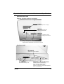
DR 300
Operation Manual
SATO Group of Companies
BARCODE SATO INTERNATIONAL PTE
LTD
438A Alexandra Road #05-01/ 02,
Alexandra Technopark,
Singapore 119967
Tel: +65-6271-2122
Fax: +65-6271-2151
Website: www.barcodesato.com
Email: [email protected]
SATO EUROPE NV
Leuvensesteenweg 369,
1932 Sint-Stevens-Woluwe, Brussels, Belgium
Tel: +32 (0)-2-788-80-00
Fax: +32 (0)-2-788-80-80
Website: www.sato-europe.com
Email: [email protected]
SATO UK LTD
Valley Road, Harwich, Essex England
Co12 4RR, United Kingdom
Tel: +44-1255-240000
Fax: +44-1255-240111
Website: www.satouk.com
Email: [email protected]
SATO DEUTSCHLAND GMBH
Schaberweg 28, 61348
Bad Homburg, Germany
Tel: +49 (0)-6-1726-8180
Fax: +49 (0)-6-1726-818-199
Website: www.sato-deutschland.de
Email: [email protected]
SATO POLSKA SP Z O.O.
Ul Okolna 2, 50-422 Wroclaw
Poland
Tel: +48-71-335-23-20
Fax: +48-71-335-23-25
Website: www.sato-europe.com
Email: [email protected]
SATO AMERICA INC.
10350 Nations Ford Road Suite A,
Charlotte, NC 28273
Tel: +1-704-644-1650
Fax: +1-704-644-1662
Website: www.satoamerica.com
Email: [email protected]
SATO SHANGHAI CO, LTD
11 Floor, D, Pudong South Road 1111,
Pudong New Area, Shanghai,
China 200120
Tel: +86 (0)-21-58307080
Fax: +86 (0)-21-58307978
Website: www.barcodesato.com
Email: [email protected]
SATO BAR CODE & LABELLING SDN BHD
BAR CODE SATO ELECTRONICS (S) PTE
LTD
438A Alexandra Road #05-01/02,
Alexandra Technopark, Singapore 119967
Tel: +65-6271-5300
Fax: +65-6273-6011
Website: www.barcodesato.com
www.satosingapore.com
Email: [email protected]
BARCODE SATO (THAILAND) CO. LTD
Suite B-08-11&12, Block B Plaza Mont'
370/8 Supattra Building, 5th Floor, Rama9
Kiara, No.2, Jalan Kiara Mont' Kiara,
Road, Bangkapi, Huay Kwang
50480 Kuala Lumpur, Malaysia
Bangkok 10320, Thailand
Tel: +60-3-6203-5950
Tel: +662-719-7780-3
Fax: +60-3-6203-1209
Fax: +662-719-7784
Website: www.barcodesato.com
Website: www.barcodesato.com
Email: [email protected]
Email: [email protected]
Warning
It is essential that the safety and operating procedures contained
within this manual be brought to the attention of, and are used by,
all personnel likely to operate this printer/product.
This printer/product must only be used for the purpose for which it
was designed.
This is a Class A product. In a domestic environment this product
may cause radio interference in which case the user may be
required to take adequate measures.
Electrostatic discharges on the connector pins and on the memory
card may damage the printer.
In the case of fire, water must not be used on the product to extinguish the fire, and the appropriate type of fire extinguisher should
be readily available.
No modifications, either mechanical or electrical, should be made
to this printer/product or accessory without the written consent of
SATO Europe GmbH. Any modifications made without this consent
may invalidate guarantee claims.
Other manuals relating to this printer include additional information
relating to other aspects of the safe operation of the printer, and are
available from your SATO supplier.
All consumable waste, such as the label backing paper and used
carbon ribbon must be disposed of carefully, and in a manner that
will cause the minimum of environmental pollution.
Should you have any doubts regarding the setting, operating or any
safety aspects of this printer/product, please contact your SATO
supplier.
SATO Europe GmbH makes no guarantee that all the features
described in this manual are available in all models, and, due to
SATO’s policy of continuous development and improvement, specifications are liable to change, without notice.
Consumables
Always use SATO carbon ribbons or equivalent. The use of incorrect materials may cause malfunctions of the printer and void the
warranty.
Conventions
Text that appears bold italic and all in capitals such as LABEL
refers to a key or an LED on the operation panel.
Text that appears enclosed in brackets such as <ESC> refers to an
Escape sequence of a data string.
Text that appears bold italic such as On-Line refers to a function or
to a result.
Text that appears in bold such as VR1 refers to electrical components like pins, resistors connectors and so on.
Warranty and Copyright
SATO Europe GmbH makes no guarantee of any kind with regard
to this material, including, but not limited to, the implied guaranties
of merchantability and fitness for a particular purpose.
SATO Europe GmbH shall not be liable for errors contained herein
or for any incidental consequential damages in connection with the
furnishing, performance, or use of this material.
This document contains proprietary information which is protected
by copyright.
All rights are reserved.
No part of this document may be reproduced or issued to third parties in any form whatsoever without the express permission of
SATO Europe GmbH.
The information in this document is subject to change without
notice.
© Copyright 1999 SATO Europe GmbH
Contents
1. Overview and Specifications .......................................................... 7
1.1
Dimensions ......................................................................... 7
1.2
Components ....................................................................... 8
1.3
Specifications ................................................................... 10
1.4
Ribbon .............................................................................. 14
1.5
Installation Considerations ............................................... 14
2. Configuration ............................................................................... 15
2.1
DIP Switch Settings .......................................................... 15
2.2
Default Settings ................................................................ 21
2.3
Printer Adjustments .......................................................... 23
Normal Mode .................................................................... 24
User Mode ........................................................................ 24
Print Darkness Setting ...................................................... 24
Print Speed Adjustment .................................................... 25
Vertical Offset ................................................................... 25
Horizontal Offset ............................................................... 26
3. Interface Specification ................................................................. 27
3.1
Overview ........................................................................... 27
3.2
Interface Type ................................................................... 27
3.3
The Receive Buffer ........................................................... 28
3.4
RS232C Serial Interface ................................................... 29
4. Settings ........................................................................................ 35
4.1
Setting Labels or Tags ...................................................... 35
4.2
Setting large diameter rolled label .................................... 37
4.3
Setting carbon ribbon ....................................................... 38
4.4
Pitch sensor adjustment ................................................... 39
4.5
Setting optional types ....................................................... 40
4.5.1 Dispenser ............................................................... 40
4.5.2 Cutter ...................................................................... 42
4.5.3 Dropper .................................................................. 45
4.5.4 Rewinder ................................................................ 49
4.5.5 Setting PC Card ..................................................... 50
5. Troubleshooting ........................................................................... 53
5.1
Print Quality Problems ...................................................... 53
i
5.2
Troubleshooting the RS232C (Serial) Interface ................ 55
5.3
Error Signals ..................................................................... 56
6. Maintenance ................................................................................ 57
Appendix ........................................................................................... 59
ii
Operation Manual
1.
1. Overview and Specifications
Overview and Specifications
The DR300 is a true stand-alone printer designed to meet the
needs of the most discerning users. With a resolution of 8 dots per
mm quality labels are assured. The fast 32-bit RISC processor
results in the DR300 formatting and printing labels and tags to the
highest quality and the fastest through-put speeds up to 125mm
per second. The DR300 is designed to print in both Direct Thermal
and Thermal Transfer mode.
1.1 Dimensions
High
Depth
Width
DIMENSIONS
Width
Depth
Height
Weight
21,2 cm
39,5 cm
24,0 cm
8,45 kg
POWER REQUIREMENTS
Voltage
Power Consumption
DR300
220 V (+/- 10 %)
50/60 Hz (+/- 1%)
50 Watts Idle
300 Watts Operating
7
1. Overview and Specifications
Operation Manual
1.2 Components
General
Cover
Power Switch
Fuse
Sliding Guide
AC Power
Connector
Card Cover
Ribbon
Unwind Spindle
Ribbon
Rewind Spindle
Label Supply Unit
Operation
Panel Unit
Label Guide
Touch Screen
Thermal Head
Assembly
Head Lock Lever
8
DR300
Operation Manual
1. Overview and Specifications
Operation panel unit
Displays operation and error messages
Display
For error and operation messages
LINE key
Switch start/stop printing and
ON/OFF data transmission
FEED key
Feeds label
Press FEED to align label to correct
position after changing of new label roll.
Status
Displays status of printer.
Green: Printing and data communication are enabled.
Red:
Error occured.
No light: Printing and data communication prohibited.
Display will be de-activated when Touch Screen is connected!
Card cover unit
Dip switch
Sets printer operation conditions
.
DR300
PC card slot
Adjustable Variable Resistor
Pc card slot for memory cards
Variable control for sevice adjustment.
Do not alter unless specially instructed.
PRINT: Print darkness adjustment.
OFFSET: Cut, dispense, tear off position adjustment.
PITCH: Pitch adjustment.
9
1. Overview and Specifications
Operation Manual
Back panel unit
RS-232C
(Serial interface)
Connector
KB
Touch Screen connector
Check pin
For factory adjustment
EXT Connector
Connector for external
signal interface
VR1 to VR6
For factory variable resistor
1.3 Specifications
General
Head Density
8 dots/mm
Print Method
Thermal Transfer/Direct Thermal
CPU
32-bit RISC CPU
Memory
EP-PROM 4Mb x 2
DRAM 512 Kb x 2
Print Speed
75, 100, 125 mm/second(Selectable)
Bar Code Type
UPC-A/E, EAN-8, EAN-13, NW 7
Code 39, ITF2/5, Code128, UCC/EAN128, BookLand
Bar Code Ratio
1 : 2, 1 : 2.5, 1 : 3 (Software defined)
Font Expansion
1-9 times (Both horizontally and vertically)
10
DR300
Operation Manual
1. Overview and Specifications
Head Density
8 dots/mm
Font Type
U - Font W 5 x P 9 (Alphanumeric, notation)
S - Font W 17 x P 17 (Alphanumeric, notation)
M - Font W 24 x P 24 (Alphanumeric, notation)
WB - Font W 48 x P 48 (Alphanumeric, notation)
OCR - A Font W 15 x P 22 (Alphanumeric, notation)
OCR - B Font W 20 x P 24 (Alphanumeric, notation)
**IBM 850 Code Set Table
Print Area
Max W 76 mm x P 178 mm (Optional print area expansion)
Label Size
Width 25 - 80 mm Pitch 19 - 181 mm
(Label size is inclusive of label web)
Label Thickness 0.1 - 0.26 mm
Interface
RS - 232 C (Ready / Busy, Xon / Xoff, Status - 3)
Operation
Panel
Key: LINE Key, FEED Key
LCD: 8 digits x 2 Lines (English character display, Back Lit)
[Only applicabie to Online specification only]
STATUS: 2 - color LED (Red, Green)
Adjustment VR
PRINT: Print Darkness
PITCH: Pitch adjustment
OFFSET: Print position adjustment
User Mode
1. Print Darkness
2. Print Speed
3. Vertical Offset
4. Horizontal Offset
Features
Graphics Print, Sequential Numbering, Line / Box, Print
Position Adjustment, Back,- Feed, Tear - Off, Calendar,
Inverse Image, Zero Slash Selection, Non Standard Code
Setting, Hex Dump, Customized Design Character (16 x 16,
24 x 24)
Self Check/
Detection
Head Element Broken, Paper End, Ribbon End, Head
Open,
Memory Card Error, Test Print
Options
Touch Screen Unit, Cutter Unit, Dispenser Unit, Rewinder
Unit, PC Card (JEIDA Type 11)
DR300
11
1. Overview and Specifications
Operation Manual
Paper, Carbon Ribbon Specification
Paper
Carbon ribbon
Size
Min. W 25 mm-Max W 80
mm (inciusive of label web)
Min. P 19 mm-Max W 181
mm (inciusive of label web)
Thickness
0.1 mm-0.26 mm
Type
Rolled paper
Diameter
Max outer diameter: 250 mm
Type
ST111
Length
300 m/roll
Width
Max 84 mm
Thickness
4.5 gm
Winding
Face-in type
Operating Environment Condition
Input power supply
voltage
Voltage AC 220 V +- 10%
Power consumption
50 Watts idle, 300 Watts operating
Environment condition Operating temperature 5 - 40 °C
Operating humidity
30 - 80% (No condensation)
Storage temperature
5-50 °C
Storage humidity
30 - 90% (No condensation)
Except paper and carbon ribbon
12
DR300
Operation Manual
1. Overview and Specifications
Software Specification
Online specification
Stand alone specificaton
Format registration
Recall function (Printer
main body)
Main body 10 formats
(50 fields)
Main body 10 formats
(50 fields)
Sequential numbering
Yes (Numeric only)
Yes (Numeric only)
Copy function
No
Yes
Box/Line print
Yes
Yes
Graphic
BMP file
BMP file
Reverse print
Yes
Yes
Calendar function
Increment Yes/No
Increment Yes/No
Alphanumeric table
No
Yes
10 Item f unction
(Store in PC card)
No
Yes
Price field function
No
Yes
C/D calculation
No
Yes
Input check function
No
Yes
Rotate image
Yes
Yes
Image copy
Yes
Yes
Customized character
Yes
Yes
Operating mode
Continuous mode,
cutter mode,
dispense mode,
tear off mode,
Continuous mode,
cutter mode,
dispense mode,
tear off mode,
Media size designation
Media parameter
Media parameter
Printing offset
Yes
Yes
Display setting
No
Yes
Startup d-isplay setting
No
Yes
Format control function
No
Yes
Card maintenance function No
Yes
Online maintenance
function
Yes
DR300
No
13
1. Overview and Specifications
Operation Manual
Printer Main Body Operation Unit
LCD display
unit
8 x 2 lines
Operation key Feed key
LCD display is activated when touch screen is
not connected.
Paper feeding
Line key
Temporary halts printing (print pause)
LED
2 color LED
RED : error display
GREEN: On-Iine
DIP Switch
DIPSW 1
Serial interface (Setting baud rate, etc.)
DIPSW 2
Setting operation mode, etc.
Setting Hex dump function
DIPSW 3
Setting zero slash and non-standard protocode
PITCH
Pitch adjustment
OFFSET
Cutter, dispense, tear off position adjustment
PRINT
Print darkness adjustment
Variable
control VR
1.4 Ribbon
Use only SATO thermal transfer ribbons which were formulated
expressly for use in all SATO printers. Use of other than approved
ribbons may result in unsatisfactory print quality and/or damage to
the print head and may void your warranty.
1.5 Installation Considerations
Printer operation can be affected by the printer environment. The
location of the printer should be free from dust, humidity, and sudden vibrations. To obtain optimum results from the printer, avoid
locations influenced by:
• Direct or bright sunlight since bright light will make the label sensor less responsive and may cause the label to be sensed incorrectly.
• Warm temperatures which can cause electrical problems within
the printer.
14
DR300
Operation Manual
2.
2. Configuration
Configuration
2.1 DIP Switch Settings
Three DIP switches DSW1, DSW2, and DSW3 are located in the
mechanical section of the printer and is accessed through the front
door. These switches can be used to set:
• RS232C transmit/receive parameters
• Thermal transfer or direct thermal mode
• Head check mode
• Hex dump mode
• Receive buffer size
• Operation mode
DR300
15
2. Configuration
Operation Manual
Each switch is an eight position “toggle” switch. The ON position
is always to the bottom. To set the switches, first switch the unit
Off, then position the DIP switches. After placing the switches in
the desired positions, switch the printer back on. The switch settings are read by the printer electronics when the printer is switched
on again. They will not become effective until this has been done.
RS232 Transmit/Receive Setting
Data Bit Selection (DSW1-1)
This switch sets the printer to receive either 7 or 8 bit data bits for
each byte transmitted.
DSW1
DSW1-1
SETTING
OFF
8 Data Bits
ON
7 Data Bits
ON
OFF
1
2
3
4
5
6
7
8
Parity Selection (DSW1-2, DSW1-3)
These switches select the type of parity used for error detection.
DSW1-2
DSW1-3
SETTING
OFF
OFF
No Parity
OFF
ON
Even
ON
ON
OFF
Odd
OFF
ON
ON
Not Used
DSW1
1
2
3
4
5
6
7
8
Stop Bit Selection (DSW1-4)
Selects the number of stop bits to end each byte transmission.
DSW1
DSW1-4
SETTING
OFF
1 Stop Bit
ON
2 Stop Bits
ON
OFF
1
16
2
3
4
5
6
7
8
DR300
Operation Manual
2. Configuration
Baud Rate Selection (DSW1-5, DSW1-6)
Selects the data rate (bps) for the RS232 port.
DSW1-5
DSW1-6
SETTING
OFF
OFF
9600
OFF
ON
19200
ON
OFF
4800
ON
ON
2400
DSW1
ON
OFF
1
2
3
4
5
6
7
8
6
7
8
Protocol Selection (DSW1-7, DSW1-8)
Selects the flow control and status reporting protocols.
DSW1-7
DSW1-8
SETTING
OFF
OFF
Rdy/Bsy
OFF
ON
Xon/XOff
ON
OFF
Bi-Com
(Status 3)
DSW1
ON
ON
ON
OFF
1
Reserved
2
3
4
5
Printer Set Up
Print Mode Selection (DSW2-1)
Selects between direct thermal printing on thermally sensitive
paper and thermal transfer printing using a ribbon.
DSW2
DSW2-1
SETTING
OFF
Therm Xfr
ON
Direct Therm
ON
OFF
1
2
3
4
5
6
7
8
Reserved for Future Use (DSW2-2)
DR300
17
2. Configuration
Operation Manual
Head Check Selection (DSW2-3)
When selected, the printer will check for head elements that are
electrically malfunctioning.
DSW2
DSW2-3
SETTING
OFF
Disabled
ON
Enabled
ON
OFF
1
2
3
4
5
6
7
8
5
6
7
8
Hex Dump Selection (DSW2-4)
Selects Hex Dump mode.
DSW2
DSW2-4
SETTING
OFF
Disabled
ON
Enabled
ON
OFF
1
2
3
4
Receive Buffer Selection (DSW2-5)
Selects the operating mode of the receive buffer.
DSW2
DSW2-5
SETTING
OFF
Single Job
ON
Multi Job
ON
OFF
1
2
3
4
5
6
7
8
Reserved for Future Use (DSW2-6)
18
DR300
Operation Manual
2. Configuration
Size Check (DSW2-7)
Controls the length of the loaded media to the size installed by software.
DSW2
DSW2-7
SETTING
OFF
Disabled
ON
Enabled
ON
OFF
1
2
3
4
5
6
7
8
Demand Mode (DSW2-8)
Enables the Tear-Off function for Dispenser use.
DSW2-8
SETTING
OFF
Disabled
ON
Enabled
DSW2
ON
OFF
1
2
3
4
5
6
7
8
Reserved for Future Use (DSW3-1 - DSW3-6)
Selecting Protocol Control Codes (DSW3-7)
Selects the command codes used for protocol control.
DSW3-1
DSW3
Setting
OFF
Standard
ON
ON
Non-Standard
OFF
1
2
3
4
5
6
7
8
Selecting Protocol Control Codes
Protocol control codes are the special control characters that prepare the printer to receive instructions. For example, the <ESC>
character tells the printer that a command code will follow and the
<ENQ> character asks for the printer status.
There are two pre-defined sets of Protocol Control codes to choose
from. Each set is made up of six special characters. The Standard
Protocol Control codes are non-printable characters, and the
Non-Standard Protocol Control codes are printable characters.
The Non-Standard set may be useful on host computers using protocol converters or in an application where non-printable ASCII
DR300
19
2. Configuration
Operation Manual
characters cannot be sent from the host. This manual uses the
Standard Protocol Control codes for all of the examples. Alternately, the user may define and download a set of custom Protocol
Control Codes.
Note:
If the data being sent to the printer is “Standard” and
the printer is set to “Non-Standard” the printer will
do nothing.
The Protocol Control codes are selected by a DIP switch DSW3-7
on the front panel.
Selecting Protocol Control Codes
CONTROL
STANDARD NONCHARACTER DSW2-7
STANDARD
OFF
DSW2-7 ON
DESCRIPTION
STX
02 Hex
7B Hex = {
Start of Data
ETX
03 Hex
7D Hex = }
End of Data
ESC
1B Hex
5E Hex = ^
Command code to follow
Null
00 Hex
7E Hex = ~
Cutter command
ENQ
05 Hex
40 Hex = @
Get printer status, Bi-Com mode
Can
18 Hex
21 Hex = !
Cancel print job, Bi Com mode
Off-Line
40 Hex
5D Hex = ]
Take printer Off-Line
Zero Slash (DSW3-8)
Enables or disables the slash in the Zero of all Matrix Fonts.
DSW3-8
DSW3
SETTING
OFF
Enabled
ON
ON
Disabled
OFF
1
20
2
3
4
5
6
7
8
DR300
Operation Manual
2. Configuration
2.2 Default Settings
Switch Selections
All switches are placed in the Off position (default) for shipping.
This will result in the following operating configuration:
Communications: 8 data bits, no parity, 1 Stop bit, 9600 Baud
Protocol:
Ready/Busy
Receive Buffer:
Single Job
Protocol Codes:
Standard
Software Default Settings
The printer stores the software settings upon receipt and uses
them until they are again changed by receipt of a command containing a new setting. These settings are stored in non-volatile
RAM and are not affected by switching the printer off. The printer
may be reset to use the default software settings by depressing the
LINE and FEED keys simultaneously while switching the printer on
and selecting “DEFAULT YES“. This will result in the following
default configuration:
DR300
Print Darkness
3
Print Speed
2 (100mm/s)
Print Reference
Vertical = 0000, Horizontal = 0000
Zero
Slash
Auto On Line
Enabled
Once the default operation is completed,
DEFAULT
a “DEFAULT COMPLETE” message will
COMPLETE
be displayed on the LCD panel. The
printer should be switched off while this message is being displayed. This saves the default settings in the EEPROM where they
will be automatically loaded the next time the printer is switched on.
Printer Adjustments
The LCD Panel is used in conjunction with the LINE and FEED
switches by the operator to manually enter printer configuration
settings. Many of the settings can also be controlled via software
DR300
21
2. Configuration
Operation Manual
commands and in the case of conflict between software and control
panel settings, the printer will always use the last valid setting.
POWER ON
Normal/User Mode
POWER
22
ONLINE
Q:000000
DR300
Operation Manual
2. Configuration
2.3 Printer Adjustments
The LCD Panel is used in conjunction with the LINE and FEED
switches by the operator to manually enter printer configuration settings. Many of the settings can also be controlled via software commands and in the case of conflict between software and control
panel settings, the printer will always use the last valid setting. If
you load a label job that includes software settings and then enter
a new setting via the operation panel, the manually set values will
be used by the printer. If you set the values manually and then
download a job with software settings, the software settings will be
used.
POWER ON
Normal/User Mode
POWER
Load SATO Default Settings
POWER+FEED + LINE
Print Hex Dump Label
POWER + DSW2-4 =ON
Test Print Mode
POWER+FEED
DR300
ONLINE
Q:000000
DEFAULT
COMPLETE
Receive Buffer
Hex Dump Label
TEST
S
PRN
L
23
2. Configuration
Operation Manual
Normal Mode
When the printer is switched on, the readout will display the following message.
ONLINE
Q:000000
The LCD Panel will display the ONLINE status on the top line of
the display and the bottom line will contain the label quantity (Q)
status. The ONLINE message will be changed to OFF Line whenever the print head is opened and closed. As soon as a print job is
received, the Quantity message will indicate the number of labels
to be printed. As soon as the label job begins to print, the display
will indicate the number of labels remaining in the print job that
remain to be printed.
User Mode
To enter the USER mode, perform the following steps:
STEP
PROCEDURE
1.
Press the LINE key while powering on
the printer.
OFFLINE
000000
2.
After the single audible signal
release the key.The printer now dis-
USER
MODE
plays the USER mode adjustment.
Press the FEED key and the printer displays the first USER Mode
(DARKNESS)
3.
Print Darkness Setting
There are five Darkness (or heat range) settings. The higher numbers represent darker settings. The current setting is indicated by
an underline under one of the range settings.
To change the setting perform the following steps:
STEP
24
PROCEDURE
1.
Use the LINE key to step the
underlined cursor to the desired setting.
2.
Once the correct setting is underlined, press the FEED key to
accept the setting and advance to the next adjustment.
DARKNESS
L12345D
DR300
Operation Manual
2. Configuration
Print Speed Adjustment
There are three SPEED settings on the DR300. Each setting is
listed on the bottom line of the display. The current setting is indicated by an underline under one of the speed settings.
1 = 75 mm/s
2 = 100 mm/s
3 = 125 mm/s
SPEED
123
To change the setting perform the following steps:
STEP
PROCEDURE
1.
Use the LINE key to step the underlined cursor to the desired setting.
2.
Once the correct setting is underlined, press the FEED key to accept
the setting and advance to the next adjustment.
Vertical Offset
Set the Vertical Offset value to establish a new base reference
point. To change the setting perform the following steps:
STEP
PROCEDURE
1.
Use the LINE key to switch between the positive (+) or the negative (-) selection. A positive selection moves the vertical base reference point forward (away from the print mechanism) while a
negative selection moves the vertical base reference point back
into the mechanism.
V:OFFSET
V:±0000
2.
Once the correct setting is underlined,
press the FEED key to accept the setting and advance to the adjustment.
3.
Use the LINE key to step the counter to the desired position. The
display will increment one step for each time the LINE key is pressed. If the LINE key is held down for more then two seconds, it will
automatically go into the fast scroll mode (max. 400).
4.
Once the setting is correct, press the FEED key to accept the setting and advance to the Horizontal Offset adjustment.
5.
You may wish to check your settings by printing a test label after
you have completed the adjustments to ensure that they are correct.
DR300
V:OFFSET
V:±0000
25
2. Configuration
Operation Manual
Horizontal Offset
Set the Horizontal Offset value to establish a new base reference
point. To change the setting perform the following steps:
STEP
PROCEDURE
1.
Use the LINE key to switch between the positive (+) or the negative (-) selection. A positive selection moves the horizontal base
reference point to the right side of the label in print direction, while
a negative selection moves the horizontal base reference point to
the left side of the label in print direction.
H:OFFSET
H:±0000
26
2.
Once the correct setting is underlined,
press the FEED key to accept the setting and advance to the adjustment.
3.
Use the LINE key to step the counter to the desired position. The
display will increment one step for each time the LINE key is pressed. If the LINE key is held down for more then two seconds, it will
automatically go into the fast scroll mode (max. 400).
4.
Once the setting is correct, press the FEED key to accept the setting and advance to the Print Darkness Setting.
5.
You may wish to check your settings by printing a test label after
you have completed the adjustments to ensure that they are correct.
H:OFFSET
H:±000
DR300
Operation Manual
3.
3. Interface Specification
Interface Specification
3.1 Overview
This section explains the interface specification for the DR300
printer. These specifications include detailed information on how
to properly interface your printer with your host system and
includes data about the following:
• Interface Type
• Using The Receive Buffer
• RS232C Serial Interface
3.2 Interface Type
The RS232C Serial interface allows connectivity to a number of
other hosts. For instructions on how to properly configure the
printer for either of these interface types, see the printer configuration instructions in Chapter 2 of this manual.
WARNING: Never connect or disconnect interface cables or
use a switch box with power applied to either
the host or the printer. This may cause damage
to the interface circuitry in the printer/host and
is not covered by warranty.
DR300
27
3. Interface Specification
Operation Manual
3.3 The Receive Buffer
The printers have the ability to receive a data stream from the host
in one of two ways. The receive buffer may be configured to accept
one print job at a time or multiple print jobs. The single job print
buffer is generally used by software programs that wish to maintain
control of the job print queue so that it can move a high priority job
in front of ones of lesser importance. The multiple job buffer, on the
other hand prints all jobs in the order they are received by the
printer, and the order of printing cannot be changed.
Single Job Buffer
The printer receives and prints one job at a time. Each job must
not exceed 34 K bytes. DIP Switch 2-5 (Off).
Multi Job Buffer DIP Switch 2-5 (On).
The printer is able to continuously receive print jobs, compiling and
printing other jobs at the same time. It acts much like a “print buffer”
to maximize the performance of the host and the printer. The Multi
Job Buffer mode is selected with DSW2-5. The Multi Job Buffer
uses either the Ready/Busy with DTR (pin 20) or X-On/X-Off flow
control protocols. See these sections for more details. With an
empty receiving buffer, the status of DTR is “high” (or an X-On status if using X-On/X-Off), meaning the printer is ready to receive
data. When the receive buffer is holding 32K bytes of data (2K
bytes from being full), DTR will go “low” (or an X-Off is sent) indicating the printer can no longer receive data. This condition is
called “Buffer Near Full”. See Figure 3-1.
0
32K
34K
DTR High or
X-On
DTR Low or
X-Off
Buffer Near Full
Fig.
3.1
The receiving buffer will not be able to receive more data again until
a “Buffer Available” condition occurs. This takes place when the
receiving buffer has emptied so that only 26K bytes of data are
being held (8K bytes from being full). At this time, DTR will go
28
DR300
Operation Manual
3. Interface Specification
“high” or an X-On is sent to tell the host that it can again receive
data. See Figure 3-2.
26
0
34
DTR High or
X-On
DTR Low or
X-Off
Buffer Available
Fig.
3.2
All printer error conditions (i.e., label out, ribbon out) will cause the
printer to go busy (DTR “low” or X-Off) until the problem is corrected and the printer is placed on-line. The printer will also be
busy if taken off-line from the front panel.
3.4 RS232C Serial Interface
General Specifications
Asynchronous ASCII
Half-duplex communication.
Ready/Busy Hardware Flow Control
Pin 20, DTR Control
Pin 4, RTS Error Condition
X-On/X-Off Software Flow Control.
Bi-Directional communication (ENQ/Response)
Data Transmission Rate
2400, 4800, 9600 and 19200 bps
Character Format
1 Start Bit (fixed)
7 or 8 data bits (selectable)
Odd, Even or No Parity (selectable)
1 or 2 Stop bits (selectable)
DR300
29
3. Interface Specification
Operation Manual
Electrical Specifications
Connector
PIN 13
DB-25S (Female)
PIN 1
PIN 14
PIN 25
Cable
DB-25P (Male), 1,5m maximum length. For cable configuration, refer to cable requirements appropriate to the
RS232C protocol chosen.
Signal Levels
High = +5V to +12V
Low = -5V to -12V
30
DR300
Operation Manual
3. Interface Specification
Pin Assignments
RS232C Interface Signals
PIN
DIRECTION
SIGNAL DESCRIPTION
1
Reference
2
To Host
3
To Printer
4
To Host
RTS (Request to Send) Used with Ready/Busy flow
control to indicate an error condition. RTS is high and
remains high unless the print head is open, (in this case,
RTS would return to the high state after the print head is
closed and the printer is placed back on-line) or an error
condition occurs during printing (e.g., ribbon out, label
out).
5
To Printer
CTS (Clear to Send) - When this line is high, the printer
assumes that data is ready to be transmitted. The printer will not receive data when this line is low. If this line
is not being used, it should be tied high (to pin 4).
6
To Printer
DSR (Data Set Ready) - When this line is high, the printer will be ready to receive data. This line must be high
before data is transmitted. If this line is not being used,
it should be tied high (to pin 20).
7
Reference
SG (Signal Ground).
20
To Host
DR300
FG (Frame Ground)
TD (Transmit Data) - Data from the printer to the host
computer. Sends X-On/X-Off characters or status data
(Bi-Directional protocol).
RD (Receive Data) - Data to the printer from the host
computer.
DTR (Data Terminal Ready) - This signal applies to
Ready/Busy flow control. The printer is ready to receive
data when this pin is high. It goes low when the printer
is off-line, either manually or due to an error condition,
and while printing in the Single Job Buffer mode. It will
also go low when the data in the buffer reaches the Buffer Near Full level.
31
3. Interface Specification
Operation Manual
Ready/Busy Flow Control
Ready/Busy is the hardware flow control for the serial interface on
the printer. By raising/lowering the voltage level on Pin 20 of the
RS232 port, the printer notifies the host when it is ready to receive
data. Pin 4 (RTS) and Pin 20 (DTR) are the important signals on
the printer for this method of flow control. The host must be capable
of supporting this flow control method for it to function properly.
Cable Requirements
HOST
INTERCONNECTION
PRINTER
FG
1 FG (Frame Ground)
TD
3 RD (Receive Data)
4 RTS (Request to Send)
5 CTS (Clear to Send)
6 DSR (Data Set Ready)
*
20 DTR (Data Terminal Ready)
SG
7 SG (Signal Ground)
* This connection at the host side of the interface would depend
upon the pin that is being used as the Ready/Busy signal by the
driving software. Typically on a PC, it would be either CTS (pin 5)
or DSR (pin 6) on a DB-25 connector.
X-On/X-Off Flow Control
X-On/X-Off flow control must be used whenever hardware (Ready/
Busy) flow control is not available or desirable. Instead of a voltage
going high/low at pin 20, control characters representing “Printer
Ready” (X-On = 11 hexadecimal) or “Printer Busy” (X-Off = 13
hexadecimal) are transmitted by the printer on pin 2 (Transmit
Data) to the host. In order for this method of flow control to function
correctly, the host must be capable of supporting it. X-On/X-Off
operates in a manner similar to the function of pin 20 (DTR) as previously explained. When the printer is first switched on and goes
on-line, an X-On is sent out. In the Single Job Buffer mode, when
the printer receives a print job, it transmits an X-Off and begins
printing. When it is done printing, it transmits an X-On. In the Multi
Job Buffer mode, the printer sends an X-Off when the “Buffer Near
Full” level is reached and a X-On when the data level of the buffer
drops below the “Buffer Available” mark. When the printer is taken
off-line manually, it transmits an X-Off indicating it cannot accept
32
DR300
Operation Manual
3. Interface Specification
data. When it is placed back on line manually, it sends an X-On,
indicating it is again available for receipt of data. If an error occurs
during printing (paper out, ribbon out), the printer sends nothing in
the Single Job Buffer mode since the last character transmitted was
an X-Off. When the error is cleared and the printer resumes printing, no X-On is sent until the current job is completed and the
printer is once again read to receive the next job. If it is in the Multi
Job Buffer mode, it sends an X-Off as soon as an error condition
is detected. When the error is cleared and the printer is placed
back on-line, it transmits an X-On indicating it is again ready to
accept data.
Upon switch up, if no error conditions are present, the printer will
continually send X-On characters at five millisecond intervals until
it receives a transmission from the host.
Cable Requirements
HOST
INTERCONNECTION
PRINTER
FG
1 FG (Frame Ground)
RD
2 TD (Transmit Data)
TD
3 RD (Receive Data)
4 RTS (Request to Send)
5 CTS (Clear to Send)
6 DSR (Data Set Ready)
20 DTR (Data Terminal Ready)
SG
7 SG (Signal Ground)
Bi-Directional Communications
This is a two-way communications protocol between the host computer and the printer, thus enabling the host to check printer status.
When this protocol is selected, there is no busy signal from the
printer (pin 20, DTR, is always high). The host must request the
complete status from the printer, including ready/busy. Whenever
the host requests printer status, it transmits an ENQ to the printer
and the printer will respond with its status within five milliseconds.
If printing, it will respond upon finishing the current label, then
resume printing. In order for this protocol to work properly, pin 6
(DTR) and pin 5 (CTS) must be held high by the host. One way to
ensure these pins are always in the correct state is to tie pin 20
DR300
33
3. Interface Specification
Operation Manual
(DTR) to pin 6 (DSR) and pin 4 (RTS) to pin 5 (CTS) at the printer
end of the cable.
Cable Requirements
HOST
INTERCONNECTION
PRINTER
FG
1 FG (Frame Ground)
RD
2 TD (Transmit Data)
TD
3 RD (Receive Data)
4 RTS (Request to Send)
5 CTS (Clear to Send)
6 DSR (Data Set Ready)
20 DTR (Data Terminal Ready)
SG
7 SG (Signal Ground)
If a CAN (18 hexadecimal) is received by the printer, it will cancel
the current print job and clear all data from the receive buffer.
34
DR300
Operation Manual
4.
4. Settings
Settings
4.1 Setting Labels or Tags
1.
2.
Open cover while power supply is off.
Remove label guide and set label.
Label Guide
4.
5.
To open thermal head turn head lock lever to the direction of
the arrow on the lever.
Pass paper underneath the pitch sensor and paper guide
shaft.
Pitch Sensor
DR300
Label Guide
Shaft
35
4. Settings
6.
7.
Operation Manual
Lightly push the entire paper against the paper guide designated position.
Adjust the sliding guide until it touches the label.
Paper
Guide
Sliding
Guide
8.
Turn head lock lever to the direction of the arrow to close the
thermal head. Close cover.
Thermal Head
Assembly
Head Lock Lever
36
DR300
Operation Manual
4. Settings
4.2 Setting large diameter rolled label
1.
2.
Remove right half of the cover fastened with snap rivets. Pull
out 3 snap rivets on the cover by pushing their center with finger.
Alter set position of label supply component. Alter position of
set screw.
Snap
Rivets
Label Supply
Set Screw
3.
Insert guide plate in label supply component. Set large diameter rolled paper and rolled label guide.
Guide Plate
Rolled Label
Guide
Label Guide
DR300
37
4. Settings
Operation Manual
4.3 Setting carbon ribbon
1.
2.
3
4
Open cover while power supply is off.
Open thermal head. Turn head lock lever to the direction of the
arrow on lever.
Insert carbon ribbon onto ribbon unwinder unit.
Insert carbon ribbon to the depth end. (Caution on direction of
Face-in-type winding). Set ribbon core on ribbon rewinding
unit.
Pass carbon ribbon from ribbon unwinder unit to ribbon
rewinding unit underneath the thermal print head. Fixed carbon ribbon on ribbon core with tape.
Tape
Ribbon Unwinder
Unit
Ribbon Rewinder
Unit
Head Lock Lever
38
DR300
Operation Manual
4. Settings
4.4 Pitch sensor adjustment
1.
2.
3.
Open cover while power supply is off.
Slide pitch sensor in the direction of the arrow and push it to
inner most position.
Close thermal head and cover.
Pitch Sensor
DR300
39
4. Settings
Operation Manual
4.5 Setting optional types
4.5.1 Dispenser
Setting label
1. Open thermal head by raising head lock lever.
2. Pull up pressure bracket of dispenser unit once, then pull
down.
Pressure
Bracket
3.
4.
Set label. When setting label on dispenser unit peel 3-4 labels
from backing paper and pass the backing paper under the
pressure bracket.
Lock the print head after label is set, then set pressure bracket.
Head Lock
Lever
40
DR300
Operation Manual
4. Settings
Stop position adjustment
Correct stop position for dispense mode is the position where label
is 2-3 mm on backing paper. Adjust OFFSET (VR) to obtain correct
stop position. Backwards against printing direction, forward to
printing direction.
OFFSET VR
Caution!
1.
There may be cases the dispenser does not function
properly due to the thickness of labei used.
2.
Printing accuracy at peeling is V (Vertical) direction
± 1.5 mm.
3.
Dispenser unit is effective for label pitch 25-181 mm.
However, label size limitation may vary with application conditions.
DR300
41
4. Settings
Operation Manual
4.5.2 Cutter
Paper set position
1. Open cover.
2. Set label.
3. Open thermal head by raising head lock lever.
4. Set the tip of label on platen roller.
5. Close thermal head.
6. Close cover.
Platen Roller
Head Lock Lever
42
DR300
Operation Manual
4. Settings
Cut position adjustment
Cut of Iabel.
Correct cutting position is at the label gap portion.
Adjust "OFFSET“VR to obtain the correct cut position, backwards
against printing direction, forward to printing direction. Cutting on
to the label must be avoided because glue that accumulates on the
blade will affect cutter blade sharpness.
OFFSET VR
DR300
43
4. Settings
Operation Manual
Cutting paper with perforation.
As for paper with perforationt 1 mm from perforation is non cut area.
Adjust "OFFSET" VR to obtain correct cut position.
Cutter replacement
Replace cutter when blade becomes blunt and cut edges are
snappy. (Please contact sales outlet where you purchased.)
Note:
1. Paper thickkness 0,1 mm - 0,26 mm
2. Accuracy of cut is +/- 1,5 mm
3. Paper pitch 25 - 181 mm
4. +/- 1 mm from perforation is non cut area.
44
DR300
Operation Manual
4. Settings
4.5.3 Dropper
Dropper
1. Set dropper in front of the cover of printer main body as shown
in the following drawing.
2. Attach the dropper to the front cover of printer cutter.
Tag Guide
Dropper
Basic usage of droper
1. First adjust scale position (inclination of bottom plate) corresponding to the size of paper by loosening dropper screw.
2. Adjust the scale according to label pitch for a good stacking
position.
3. The number of sheets that can be dropped varies with the
scale position and paper thickness.
DR300
45
4. Settings
Operation Manual
Stack position adjustment, standard tag (greater than 40 mm)
1. Set stacker scale in between from [Label size] to [Large].
2. Determine tag guide position by matching with the size of tag
to be cut.
Tag guide set position
1. When setting a tag guide, set it with space of approx. 3 mm on
printer main body side and approx. 3 mm side of tag.
Tag
Dropper
Tag Guide
46
DR300
Operation Manual
4. Settings
Stack position adjustment, small tag (less than 35 mm)
1. Set stacker scale in between from [Label size] to [Short].
2.
3.
Set guide plate to stacker. This guide plate works to prevent
overturning, when small pitch tag is issued.
Determine tag guide position by matching to size of tag to be
cut.
Tag Guide
Guide Plate
DR300
47
4. Settings
Operation Manual
Tag guide set position.
1. When setting tag guide, set it with space of approx. 3 mm on
printer main body side and approx. 3 mm on side of tag as
shown in the following drawing.
Tag
Dropper
Tag Guide
48
DR300
Operation Manual
4. Settings
4.5.4 Rewinder
Paper set position
1. Open cover.
2. Set label.
3. Open thermal head by raising head lock lever.
4. Feed the labels through the print area in the normal manner.
Feed the labels out and attach to an empty core on the rewind
spindle. Wind some revolution to ensure the labels are secure
on the core.
5. Close thermal head.
6. Close cover
Rewinder
Rewind
Spindle
DR300
Head Lock Lever
49
4. Settings
Operation Manual
4.5.5 Setting PC Card
Printing format and graphic data can be stored in PC card. 128K,
256K, 512K, 1 M, 2M bytes TYPE 11 PCMCIA memory cards
(JEIDA Ver4.2/ PCMC1A2 equivalent) are available.
Installation.
1. Power off printer and open card cover. There are 2 card slots
available.
2. Insert memory card into the designated slot.
3. Confirm direction of memory card before inserting into the slot.
Take caution not to force the card in reverse direction that may
damage the connector of the memory card as well as the connector on the main PCB.
4. Confirm projection of eject button on the right hand side of the
slot when memory card is inserted properly.
2 Slots
Eject
Buttons
Removal
1. Push the eject button at the right side of the card slot.
2. Remove the slightly ejected memory card.
Caution!
1.
Ensure that power is switched oft when installation
and removal of any memory card to prevent any possible damage to the memory card, connectors and
printer.
2.
Close card cover to prevent intrusion of hazardous
objects when no card is in the slot.
50
DR300
Operation Manual
4. Settings
3.
Please use memory card which complies with TYPE
11 JEIDA Ver. 4.2/PCMCIA 2.1 (self-contained battery
type) standard.
4.
Replace memory card battery when printer prompts
low battery message.
Battery installation/exchange
1. Confirm and identify the followings:
A. Memory Card
B. Coin type lithium battery (BR2325 type) and small screw
driver (used for battery installation).
A
B
2.
Pull out the battery holder for memory card.
Turn the screw anti-clockwise 2-3 times with screw driver and
pull out the battery holder.
The battery holder is made to be locked on its way as not to
be drawn out completely.
Battery Holder
W/P
Screw
DR300
51
4. Settings
3.
Operation Manual
Replace battery.
Set battery on the battery holder.
Push it in the battery holder and lock it by turning the screw
2-3 times in clockwise direction with screw driver.
Take caution not to touch the battery with bare hands to prevent poor contact.
Periodically replace the memory card battery.
When any new memory card is used, it must be formatted.
Battery
Battery Holder
Screw
Special remarks
• Ensure the battery is installed in the card to preserve stored
information.
• Avoid drop or hit it against hard objects. Do not bend the card.
• Do not wet the card.
• Avoid placing under direct sun light and near heating objects.
• Keep the connector clean from dust and dirt.
• Do not touch the connector with bare hand.
• Avoid high temperature and high humidity environment.
• Keep in soft case when not in use to prevent static charge.
Please read the instructions provided by manufacturer carefully.
52
DR300
Operation Manual
5.
5. Troubleshooting
Troubleshooting
5.1 Print Quality Problems
Nothing is displayed on the display
Check Point
Remedy
lf power cable is firmly plugged into Plug power cable again in the outlet
the power outlet?
firmly.
lf power cable is firmly plugged into Plug power cable again in the power conthe equipment?
nector firmly?
lf power cable is damaged?
Replace power cable.
If Fuse on is OK?
Check the fuse at the back of printer. lf it
was blown, exchange with equivalent
fuse.
lf it is blown again after exchange, contact local dealer.
lf current is supplied to the outlet
Check power source for the power supply
for power supply to the equipment? outlet. lf there is not problem for the
power source, check the electricity supply of the building.
Check for any power shut down.
Paper feeds, but no printing
lf thermal head is dirty or label
sticks on, it?
Clean dirt off from thermal head with cleaning kit if print head is dirty. Avoid using
metallic tool which may damage print
head.
lf genuine label, carbon ribbon
exclusively for the equipment are
used?
Genuine label, carbon ribbon exclusively
for this equipment must be used.
lf pitch sensor is dirty?
Clean dirt off from pitch sensor with cleaning kit.
Poor print image
lf label, carbon ribbon are properly
set?
DR300
Check if label, carbon ribbon are fixed
firmly and at correct position by lifting
head assembly.
53
5. Troubleshooting
Operation Manual
lf printing darkness is too light or
too dark?
Reset print darkness via user mode setting.
lf platen roller is dirty?
Wipe dirt off from the platen roller with
cleaning kit.
lf thermal head is dirty or
label sticks on it?
Clean dirt or label glue off from thermal
head with cleaning kit.
Remove label if it sticks on the print head.
Avoid removing with metallic tool to prevent damage to the print head.
lf dirty label is used?
Use clean label.
lf genuine label, carbon ribbon
exclusively for the equipment are
used?
Genuine label, carbon ribbon exclusively
for this equipment must be used.
Print image shifts from its position.
If label, carbon ribbon are properly Check if label, carbon ribbon are fixed
set?
firmly and at correct position by lifting
head assembly.
lf platen roller is dirty?
Clean dirt off from the platen roller with
cleaning kit.
lf deformed label, carbon ribbon is
used?
Use new label, carbon ribbon which are
in good conditions.
lf genuine label, carbon ribbon
exclusively for the equipment are
used?
Genuine label, carbon ribbon exclusively
for this equipment must be used.
lf content of data, signal from the
computer are correct?
Reset printer with power off/on.
lf similar message is displayed, check
content of software and communication
configuration settings at the computer
side.
lf print position offset setting is cor- Adjust print position offset.
rect?
54
DR300
Operation Manual
5. Troubleshooting
5.2 Troubleshooting the RS232C (Serial) Interface
1. Is the RS232C Serial cable connected securely to your serial
port on the PC (DB-9S Male) and to the RS232C connector on
the printer?
Warning: Never connect or disconnect interface cables (or
use a switch box) with power applied to either the printer or
the host. This may cause damage to the interface circuitry and
is not covered by warranty.
2. Is the cable defective? At the very least, you should be using a
“Null Modem Cable,” which crosses pins in a specific manner.
This should enable your printer to print. We recommend that
you use a cable built to specifications described in Chapter 3,
Interface Specifications.
3. Check for obvious errors in the data stream. Remember that all
print jobs for serial data must be framed by an STX and ETX.
4. If after sending your job to the printer, it only “beeps” (or displays
a Framing Error message on the LCD panel), you may have a
configuration problem. There may be some inconsistencies with
the Baud Rate, Parity, Data Bits, or Stop Bits in relation to your
host computer. If you are confused as to what the printer’s current RS232 settings are, you may choose the SATO defaults (all
DIP switches in the OFF position) to achieve 9600 baud, no parity, 8 data-bits, and 1 stop bit).
5. If you still are unable to get printer output, try the Hex Dump. In
this case, the printer monitors its RS232C interface for incoming
data.
DR300
55
5. Troubleshooting
Operation Manual
5.3 Error Signals
LED
On
On
On
Blinks
Blinks
Blinks
Blinks
Blinks
On
On
On
On
Blinks
Blinks
Blinks
56
LCD
AUDIBLE
MESSAGE
BEEP
MACHINE
ERR
HEAD ERR
SENSOR
ERR
CARD R/W
ERR
CARD
LO-BATT1
CARD
LO-BATT2
HEAD
OPEN
CUTTER
ERR
PARITY
ERR
OVERRUN
ERR
FRAMING
ERR
BUFFER
ERR
PAPER
END
RIBBON
END
MEDIA
ERR
1 Long
ERROR
CONDITION
TO CLEAR
Machine Error Switch power ON/OFF
1 Long
3 Short
Head
Sensor
Switch power ON/OFF
Switch power ON/OFF
1 Long
Switch power ON/OFF
3 Short
Memory Card
Read/Write
Memory Card
Battery Low
Memory Card
Battery End
Head Open
3 Short
Cutter
Switch power ON/OFF
3 Short
Switch power ON/OFF
3 Short
RS232 Parity
Error
RS232 Overrun
Error
RS232 Framing Error
Buffer Overflow
3 Short
Label End
3 Short
Ribbon End
3 Short
Media Error
1 Long
1 Long
3 Short
3 Short
Switch power ON/OFF
Switch power ON/OFF
Close head lever
Switch power ON/OFF
Switch power ON/OFF
Switch power ON/OFF
Open/close Head
Reload paper
Open/close Head
Reload ribbon
Open/Close Head
Lever
DR300
Operation Manual
6.
Maintenance
Maintenance
This equipment is for printing important information in the form of
bar code and character.
Periodical preventive maintenance is recommended to keep the
printer in good condition.
Timing for maintenance.
Thermal head, platen roller:
After printing every one roll or 150 m of label.
Others:
After printing every 6 rolls or 900 m of label.
Caution for maintenance!
1.
The above recommended cleaning frequency is just
an estimation. Do carry out any cleaning when dirt or
dust gathered.
2.
Use applicator and cotton cloth for cleaning each
component. Avoid metallic tools to prevent damage
to printer parts especially print head.
3.
Ensure that power is switched off before performing
any cleaning.
Cleaning method for printer parts
Cleaning of label supply unit and label guide shaft unit. Label guide
shaft unit can be removed by removing a set screw.
Label Supply
Unit
Label Guide Shaft
DR300
57
6. Maintenance
Operation Manual
Cleaning for pitch sensor unit. Pull out pitch sensor guide unit and
clean its bottom portion. If label stuck, remove pitch sensor guide
unit from the shaft groove by pulling the stopper in the arrow direction, pull it out and clean its bottom area.
Print head unit. Clean print head unit and platen roller
Print Head
Platen
Roller
Pitch Sensor Unit
Cleaning with rubbing sheet. Usage of rubbing sheet is indicated
on the rubbing sheet.
58
DR300
Operation Manual
Appendix
Appendix
DR300
59
Appendix
Operation Manual
This page is intentionally left blank.
60
DR300