1
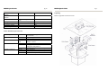
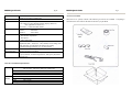
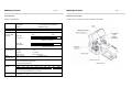
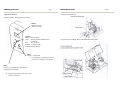
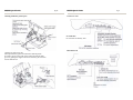
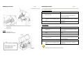
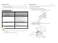
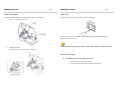
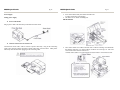
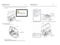
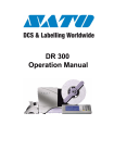
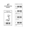
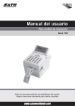
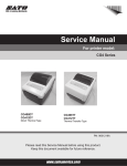
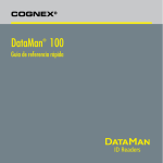
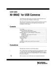
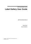
DR300 (HQ) (Japan) (Singapore) (Malaysia) (Thailand) (China) (USA) (Belgium) (Germany) (Poland) (UK) (Holland) SATO International Pte. Ltd. SATO Corporation SATO Asia Pacific Pte. Ltd. SATO Auto-ID Malaysia Sdn. Bhd. SATO Auto-ID (Thailand) Co., Ltd SATO Shanghai Co., Ltd SATO America, Inc. SATO Europe NV SATO Deutchland GmbH SATO Polska SP Z O.O. SATO UK Ltd SATO Rotterdam Logistics Center Factory : (Malaysia) (Malaysia) SATO Malaysia Electronics Manufacturing Sdn. Bhd. SATO Labelling Malaysia Electronics Sdn.Bhd. Quick Guide DR300 Quick Guide Pg 33 DIPSW 3 No. 1 2 3 SATO Asia Pacific Pte. Ltd. 438A Alexandra Road #05-01/02 Alexandra Technopark Singapore 119967 Tel : (65) 6271 5300; Fax : (65) 6273 6011 Sales Hotline : (65) 6276 2722; Service Hotline : (65) 6273 6455 Email : [email protected] Website : www.satoworldwide.com © Copyright 2003 SATO Asia Pacific Pte. Ltd. Warning : This equipment complies with the requirements in Part 15 of FCC rules for a Class A computing device. Operation of this equipment in a residential area may cause unacceptable interference to radio and TV reception requiring the operator to take whatever steps necessary to correct the interference. All rights reserved. No part of this document may be reproduced or issued to third parties in any form whatsoever without the express permission of SATO Asia Pacific Pte. Ltd. The materials in this document are provided for general information and are subject to change without notice. SATO Asia Pacific Pte. Ltd. assumes no responsibilities for any errors that may appear. SAP/DR300/QG/Jan05/02 4 5 6 7 8 Setting ON OFF ON OFF ON OFF ON OFF ON OFF ON OFF ON OFF ON OFF Content Enable: Change parameter by touch screen Enable: Change parameter by touch screen (Reserved) (Reserved) (Reserved) (Reserved) (Reserved) (Reserved) (Reserved) (Reserved) (Reserved) (Reserved) Non-standard protocode Standard protocode Zero without slash Zero with slash DR300 Quick Guide Pg 32 DR300 Quick Guide Pg 1 Table of Contents Separate sheet 3 (Protocol setting) 7 ON ON OFF OFF 8 ON OFF ON OFF Content (Reserved) STATUS 3 XON-XOFF Ready/Busy DIPSW 2 No. 1 2 3 4 5 6 7 8 Setting ON OFF ON OFF ON OFF ON OFF ON OFF ON OFF ON OFF ON OFF Content Direct Thermal Thermal Transfer (Reserved) / Reflecting type sensor (Reserved) / See through type sensor Head Check, Yes Head Check, No Hex dump function, Yes Hex dump function, No Multi items receive mode 1 item receive mode (Reserved) (Reserved) Size detection, Yes Size detection, Yes Tear off (Dispense), Yes Tear off (Dispense), No * Pitch sensor (DSW2-2) is effective only during service, test print. It is void during test print. What You Get …………………………………………………………….. Unpacking ………………………………………………………………… Unpacking – Touch Screen (Optional Item) ……………………... Accessories Checklist …………..................................................... Name of Parts …………………………………………………………….. Touch Screen / Keypad ………………………………………….. Operation Panel Unit …………………………………………….. Card Cover Unit …………………………………………………. Back Panel Unit ………………………………………………….. Media Loading …………………………………………………………… Setting of Label and Carbon Ribbon …………………………….. Setting Rolled Paper ……………………………………………... Setting Large Diameter Rolled Label ……………………………. Setting Carbon Ribbon …………………………………………… Pitch Sensor Adjustment ………………………………………………… Power Supply ……………………………………………………………... Simple Troubleshooting ………………………………………………….. Daily Maintenance ………………………………………………………... Serial Interface ……………………………………………………………. Specifications ……………………………………………………………… Basic Specifications ……………………………………………… Label and Carbon Ribbon Specifications ………………………… Operating Environment Condition ……………..………………… DR300 Software Specifications ………………………………….. Printer Main Body Operation Unit ……………………………………… DIP-Switch Setting ………………………………………………………... DIPSW 2 …………………………………………………………………… DIPSW 3 …………………………………………………………………… 2 3 4 5 6 7 8 9 9 10 10 10 13 14 16 18 20 23 26 27 27 28 29 29 30 31 32 33 DR300 Quick Guide Pg 2 DR300 Quick Guide Pg 31 DIP-Switch Setting What You Get The DR300 printer comes packed in a protective carton. Included in the carton are the following items: • • • • • • • • • • • DR300 Printer Quick Guide Driver / Manual CD-Rom 2-Pin Power Cable or 3-Pin Plug Head Cleaning Sheet Sample Ribbons Ribbon Take-up Core Cleaning Solution Cleaning Cloth Ribbon Part List Maintenance Contract After taking the DR300 Printer out from the carton and removing the protective plastic cover, it is ready for installation. Installation and Handling Instruction Place of installation • Place on level surface • Avoid vibration • Avoid high temperature and humidity • Avoid high environment Power Supply • AC220/240V power supply is needed • Supply electricity from main power supply • Three pin earthed power lead is required • A maximum of 3 amp fuse link is recommended DIP-Switch Setting DIP Switch shall be set when printer is off. Each DIPSW setting is described below. *All are set to OFF position as factory defaults. No. 1 Setting ON OFF Separate Sheet 1 Content Data bit No. = 7 Data bit No. = 8 Parity setting (None, Even, Odd) 4 ON OFF Stop bit = 2 Stop bit = 1 5 6 Separate Sheet 2 Baud rate setting (2400, 4800, 9600, 19200) 7 8 Separate Sheet 3 Protocol setting (Ready/Busy, Xon-Xoff, Status-3) 2 3 Separate sheet 1 (Parity setting) 2 ON ON OFF OFF 3 ON OFF ON OFF Content (Reserved) Odd Even None Separate sheet 2 (Baud rate setting) 5 ON ON OFF OFF 6 ON OFF ON OFF Content 2400 bps 4800 bps 19200 bps 9600 bps DR300 Quick Guide Card maintenance function Online maintenance function 2D Codes Truetype fonts Preset data ₤ p currency change Adjustable guard bars Pg 30 No Yes Unpacking No Yes Remove equipment from the carton box. Yes (PDF 417, QR, Data code) Yes (S/ware or card) No No Software No Yes (Card stored) Yes (1MB card, 900 sets) Yes Yes Printer Main Body Operation Unit LCD Display Unit 8 x 2 lines Operation Key Feed Key Line Key 2 colour LED DIPSW 1 DIPSW 2 LED DIP Switch Variable Control VR DR300 Quick Guide DIPSW 3 PITCH OFFSET PRINT LCD display is displayed when touch screen is not connected. Paper feeding. Temporary halts printing (print pause) RED : error display GREEN : On-line Serial interface (setting baud rate, etc) Setting operation mode, etc. Setting Hex dump function Setting zero slash and non-standard protocode Pitch adjustment Cutter, dispense, tear off position adjustment Print darkness adjustment Pg 3 DR300 Quick Guide Unpacking – Touch Screen (Optional Item) Remove touch screen from the carton box. Pg 4 DR300 Quick Guide Pg 29 Operating Environment Condition Input Power Supply Voltage Power Consumption Environment Condition Voltage AC 220V + - 10% Max 190 VA 130W Operating temperature 5~40 d.c. Operating humidity 30~80 d.c. (No condensation) Storage temperature -5~60 d.c. Storage humidity 30~90 d.c. (No condensation) Except paper and carbon ribbon DR300 Software Specifications Format registration Recall function (Printer Main Body) Sequential Numbering Copy Function Box/Line Print Graphic Reverse print Calendar function Alphanumeric table 10 Item function (Store in PC card) Price field function C/D Calculation Input check function Rotate copy Image copy Customised character Mode Media size designation Printing offset Display setting Startup display setting Format control function DR300 Software Specification On-line specification Stand alone specification Stand alone specification (50 fields + 50 formats on card) Yes (Numeric only) No Yes BMP file Yes Yes No No Yes (Numeric) Yes Yes BMP file Yes Yes Yes Yes (card stored) No No No Yes No No Continuous mode, cutter mode, dispense mode, tear off mode. Media parameter Yes No No No Yes Yes Yes Yes Yes Yes Continuous mode, cutter mode, dispense mode, tear off mode. Media parameter Yes Yes Yes Yes DR300 Quick Guide Label Size Label Thickness Operation Panel Adjustment VR User Mode Features Self Check/Detection Option Pg 28 Width 32 -80 mm Pitch 19 – 181 mm (Label size is inclusive of label web) 0.1 – 0.26 mm Key: LINE Key, FEED Key LCD: 8 digits x 2 lines (English character display, Black Lit) (only applicable to On-line use) STATUS: 2 – colour LED (Red, Green) PRINT : Print Darkness PITCH : Print Pitch OFFSET : Print Offset 1. Print Darkness 2. Print Position Adjustment 3. Print Speed 4. Offset Adjustment Graphics Print, Sequential Numbering, Line/Box, Print Position Adjustment, Back – Feed, Tear – Off, Calendar, Inverse Image, Zero Slash Selection, Non Standard Code Setting, Hex Dump, Customized Design Character (16 x 16, 24 x 24 dots) Head Element Broken, Paper End, Ribbon End, Head Open, Memory Card Error, Test Print Touch Screen Unit, Cutter Unit, Dispenser Unit, PC Card (JEIDA Type II), Scanner, cut Ticket/Tag Receiver, Full Qwerty Keyboard, Rewind Unit. Label & Carbon Ribbon Specification Label Carbon Ribbon Size Thickness Type Diameter Type Length Width Winding Min. W32 mm – Max W80 mm (incl. of label web) Min. P19 mm – Max W181 mm (incl. of label web) 0.1 mm – 0.26 mm Rolled Paper Max. outer diameter : 250 mm Wax, Wax/Resin 300m/roll Max. 84 mm Face-in type DR300 Quick Guide Pg 5 Accessories Checklist When the box is opened, confirm if the following accessories are included. If anything is found short, the sales outlet or the dealer from where you purchased. Cleaning Sheet DR300 Quick Guide Name of Parts Pg 6 DR300 Quick Guide Pg 27 Specifications Basic Specification DR300 General Specifications Head Density Print Method CPU Print Speed Bar Code Type Bar Code Ratio Font Expansion Font Type Print Area 8 dots/mm Thermal Transfer/Direct Thermal 32-bit RISC CPU 75, 100, 125 mm/second (Selectable) UPC-A/E EAN-8 EAN-13 NW7 Code 39 ITF2/5 Code 128 UCC/EAN128 Bookland 2D: PDF417, Data Matrix, Vericode, QR code, Maxicode *2D barcode: online printing only 1:2, 1:2.5, 1:3 (Software defined) 1-9 (Both horizontally and vertically) U – Font** S – Font** M – Font** OCR – A Font OCR – B Font WB – Font WL – Font W5xP9 W17xP17 W24xP24 W19xP22 W20xP24 W48xP48 W48xP48 (Alphanumeric, notation) (Alphanumeric, notation) (Alphanumeric, notation) (Alphanumeric, notation) (Alphanumeric, notation) (Alphanumeric, notation) (Alphanumeric, notation) **IBM 850 Code Set Table Max W 80 mm x P 178 mm (Optional print area expansion) DR300 Quick Guide Pg 26 DR300 Quick Guide Serial Interface Touch Screen / Keypad Interface Specifications Touch screen is connected to printer main body with a cable. Protocol Baud rate Sychronize Maximum receive buffer capacity Ready/Busy XON/OFF Status 3 2400, 4800, 9600, 19200 BPS Asynchronous mode 32K OK Near full occurrence (1 item, multi items selectable) (1 item, multi items selectable) (Multi item only) 32K 2Kbytes remained Near full cancellation Character construction Data Specification Connector Transmission format Signal level 8Kbytes remained 7 or 8 bit 1 bit 1 or 2 bit Even, Odd, None Graphic (8 bit) Data bit Start bit Stop bit Parity check ASC II (7 bit) Printer side DB-25S (Equivalent) Cable side DB-25P (Equivalent) Cable length less than 5m Start b1 b2 b3 b4 b5 Note : b8 is omitted when set to 7 bit data High level : +5 ~ +12 V Low level : -5 ~ 12 V b6 b7 b8 Stop Pg 7 DR300 Quick Guide Pg 8 DR300 Quick Guide Cleaning with rubbing sheet. Operation Panel Unit Displays operation message and error message Display Display error and operation message. STATUS Displays status of printer Green : Printing and data communication are enabled Red : Error occurred No Light : Printing and data communication prohibited FEED Feed Key : Feeds Label • Press FEED key to align label to correct position after changing new label roll LINE Line Key : Switch Start/Stop printing and ON/OFF data transmission Display will be de-activated when Touch Screen is connected Usage instruction of rubbing sheet is indicated on the rubbing sheet. Pg 25 DR300 Quick Guide Cleaning method for printer parts Pg 24 DR300 Quick Guide Card Cover Unit PC Card Slots PC cards slots for memory card. Back Panel Unit Cleaning for pitch sensor unit. Pull out pitch sensor guide unit and clean its bottom portion. If a label is stuck, remove pitch sensor guide unit from the shaft groove by pulling the stopper in the arrow direction, pull it out and clean its bottom area. Pg 9 DR300 Quick Guide Media Loading Setting of Label and Carbon Ribbon Setting paper Use of genuine SATO labels for this equipment is recommended. Pg 10 DR300 Quick Guide Pg 23 Daily Maintenance This equipment is for printing information in the form of bar code and character. Periodical preventive maintenance is recommended to keep the printer in good condition. Timing for maintenance Rolled Label • • Thermal head, platen roller. After printing every one roll or 150m of label. Others. After printing every 6 rolls or 900m of label. Caution for maintenance (Take following caution in maintenance work) • • Setting Rolled Paper • The above recommended cleaning frequency is only a guide. Do carry out any cleaning where dirt or dust has gathered. Use applicator and cotton cloth for cleaning each component. Avoid metallic tools to prevent damage to printer parts especially print head. Ensure that power is switched off before performing any printing. Maintenance Method • Printer cleaning kit. A cleaning kit is available from SATO. This contains: 1) Solvent wipes (for print head) 2) Multi purpose wipes 3) Air duster This will help to keep your printer in good working condition. DR300 Quick Guide Pg 22 Print image shifts from its position 1. Check Point Are the labels, carbon ribbons properly set? 2. Is the platen roller dirty? 3. Are deformed labels, carbon ribbons being used? Are genuine labels, carbon ribbons exclusively for this equipment being used? Is the content of data, signal from the computer correct? 4. 5. 6. • Is the print position offset setting correct? DR300 Quick Guide Pg 11 • To open thermal head, turn head lock lever in the direction of the arrow. • • Pass paper underneath the pitch sensor and paper guide shaft. Lightly push the entire paper against the paper guide designated position as shown in the picture below. • Adjust the sliding guide until it touches the label. Remedy Check if labels, carbon ribbons are fixed firmly and at the correct position by lifting head assembly. Clean dirt off from platen roller with cleaning kit. Use genuine SATO new labels, carbon ribbons which are in good condition. Genuine labels, carbon ribbons exclusively for this equipment must be used. Available from SATO. Re-set printer with power off/on. If similar message is displayed, check content of software and communication settings at the computer side. Adjust the print position. Disconnect printer from mains before cleaning. DR300 Quick Guide Pg 12 DR300 Quick Guide Pg 21 Paper fed, but no printing 1. 2. 3. Check Point Is the thermal head dirty or is there a label stuck on it? Are genuine labels, carbon ribbons exclusively for the equipment being used? Is the pitch sensor dirty? Remedy Clean dirt off thermal head with cleaning kit. *Avoid using metallic tools which may damage the print head. Genuine labels, carbon ribbons exclusively for this equipment must be used. Available from SATO. Clean dirt off from pitch sensor with cleaning kit. Poor print image • • Close the thermal head by turning the lock lever to the direction of the arrow. Close cover. NOTE If thermal transfer in use, ensure correct ribbon is installed. 1. 2. 3. Check Point Are the labels, carbon ribbons properly set? Is the print darkness too light or too dark? Is the platen roller dirty? Remedy Check if labels, carbon ribbon are fixed firmly and at the correct position by lifting head assembly. Re-set the print darkness via user mode setting. Wipe dirt off the platen roller with cleaning kit. Clean dirt or label glue from thermal head with cleaning kit. Remove label if it is stuck onto the print head. Use clean label. Genuine labels, carbon ribbons exclusively for this printer must be used. Available from SATO. 4. Is the thermal head dirty or is there a label stuck on it? 5. 6. Is the label used dirty? Are genuine labels, carbon ribbons exclusively for the equipment being used? • Disconnect printer from mains before cleaning. DR300 Quick Guide Pg 20 Simple Trouble Shooting Confirm the following items when operation of this equipment failed when the power supply is on. Nothing is displayed on the display 1. 2. 3. 4. • • Check Point Is the power cable firmly plugged into the power cable? Is the power cable firmly plugged into the equipment? Is the power cable damaged? Is the fuse on the main body fine? 5. Is there current supplied to the equipment? 6. Is the power source fuse or the circuit breaker for the building out? Remedy Plug power cable again into the outlet firmly. Plug power cable again into the power connector on the main body firmly. Replace power cable. Check the fuse at the right side of main body. If it is blown, exchange with equivalent fuse. If it blows again after exchange, contact SATO service engineer. *Please ensure printer is disconnected from the mains before exchanging fuse. Check power source for power supply outlet. If there is no problem with the power source, check the electricity supply of the building. Check for any power shut down. Contact the building maintenance office. Do not operate power switch or plug in/out power cable with wet hands to avoid electrocution. Disconnect printer from mains before printing. DR300 Quick Guide Setting Large Diameter Rolled Label Method for setting large diameter rolled paper explained. • Remove right half of the cover fastened with snap rivets. • Pull out 3 snap rivets on the cover by pushing their centre with finger. • • • • Alter set position of the label holder. Alter position of the set screw. Insert guide plate in label supply component and rolled label guide. Set large diameter rolled paper. Pg 13 DR300 Quick Guide Pg 14 DR300 Quick Guide Setting Carbon Ribbon Supply Power Only SATO carbon ribbons are recommended for the use on this printer. • Open cover while power is OFF. Turn power switch on. Push the switch on the side labelled [-]. Pg 19 When the power switch is switched on, initial startup message [Manual Print Mode] is displayed on the touch screen. • Open thermal head. Turn head lock lever to the direction of the arrow. Do not operate switch or plug in/out power cable with wet hands to avoid electrocution. Switch Off Power Supply The Following Must Be Done Before Power Off • • Confirm printer is not in action (idling). Stop or pause any printing process before switching off. DR300 Quick Guide Pg 18 Power Supply Setting power supply Power Cable Outlet DR300 Quick Guide Pg 15 • Insert carbon ribbon fully onto ribbon unwinder unit. (Caution on direction of unwinding) • Set ribbon core on ribbon rewinding unit. SEE DIAGRAM Plug in power cable to the main body socket then the outlet socket. Connect Touch Screen To Printer Unit Touch Screen comes with a cable to connect to printer main body. Plug in this connecting cable to the connector (KB) at the back of printer main body as shown below. Hold printer main body with one hand when plugging in the connecting cable. • Pass carbon ribbon from ribbon unwinder unit to ribbon rewinding unit underneath the thermal print head. Fix carbon ribbon on ribbon core with tape, etc. and wind several times in the direction of the arrow. Confirm carbon ribbon is set as the drawing on the left side by viewing from its side. DR300 Quick Guide • • Pg 16 DR300 Quick Guide Pg 17 By turning the head lock lever to the direction of the arrow, close thermal head. Close cover. Take caution not to trap your finger when closing the cover • Pitch Sensor Adjustment • Open cover when power is OFF. • Pitch sensor adjustment. Slide pitch sensor to locate centre hole. This need to be done when using tickets/tags with through punch hole only. Turn head lock lever to the direction of the arrow, close thermal head and close cover.