1
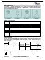
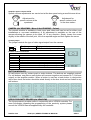
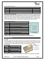
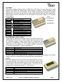
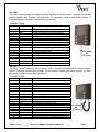
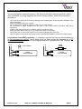
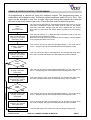
4000 SERIES (4+1)
VANDAL RESISTANT
DOOR ENTRY SYSTEM
TECHNICAL MANUAL
EDITION 1.1
CONTENTS
Manual introduction
System introduction
System components
Codelock programming instructions
Accessories
Installation
Cable size guide
Testing the system
Panel care
Accessories connection guide
Single entrance single button audio wiring diagram
Single or multiple entrance, multiple button audio wiring diagram
Single entrance video system wiring diagram
Multiple entrance video system wiring diagram
Troubleshooting guide
PAGE 2 of 24
VR4K (4+1) SERIES TECHNICAL MANUAL
PAGE
3
3
3 – 13
15 – 16
13 – 14
14
17
17
17
17 – 18
19
20
21
22
23
VER1.1
MANUAL INTRODUCTION
The information in this manual is intended as an installation and commissioning guide for
the vandal resistant 4000 Series door entry systems. This manual should be read carefully
before the installation commences. Any damage caused to the equipment due to faulty
installations where the information in this manual has not been followed is not the
responsibility of Videx Security Ltd.
VIDEX run free training courses for engineers who are not familiar with the Videx product
range. Technical help is also available on 0191 224 3174 during office hours or via e-mail
[email protected].
SYSTEM INTRODUCTION
This kit will enable a caller at an entrance point to signal an occupant in the dwelling by
pressing a call button which will send an electronic call tone to an audio telephone. A
Yellow ‘SPEAK’ LED will indicate the call has been answered and a two way conversation
can take place, the occupant can release an electric lock release by pressing a button on
the telephone base unit. The output for the lock is a dry contact relay allowing any type of
lock can be used with an appropriate PSU. If this system is to be used with a gate, the dry
contact output can be used to trigger the gate control board. DDA features such as a
‘SPEAK’ LED, ‘DOOR OPEN’ LED and reassurance tones are standard on this system.
The system is available modular and non-modular. The modular system allows a door
panel to be assembled from a range of modules including amplifiers, button modules,
camera modules and access control modules. The modules are then assembled into the
4000 Series frames using the brackets and screws supplied.
SYSTEM COMPONENTS
The system comprises of door panels, telephones/videophones and power supplies.
Relays will also be used on multiple door video systems but there are no switches required
for multiple door audio systems as was the case with the older systems. The door panel
may be made up of several parts including modules and a surface or flush frame. These
modules are easily assembled into the frames using the brackets and screws supplied with
each module. The order in which the modules fit into the frames is down to customer taste
but we would suggest keeping the amplifier module as far from the microphone holder as
possible to avoid Larsen affect.
DOOR PANEL
The vandal resistant door panel will consist of an amplifier, buttons, frame/back box and
optional items such as camera and access control features (Codelock, proximity etc).
Frame sizes are available for 1, 2, 4, 6 and 9 modules in both surface and flush fitting
configurations. Call buttons can be engraved to suite the apartment numbers.
PAGE 3 of 24
VR4K (4+1) SERIES TECHNICAL MANUAL
VER1.1
AMPLIFIER (Art.136)
The amplifier is the most important part of the system and controls the operation of the
system including speech, door release call to apartment etc. It contains a microprocessor
which controls all of these features.
Amplifier module connections
Connection
1
2
+
5
T
PTE
C
NC
NO
D+
DBSY
SL
F1
Function
Receive speech from apartment
Transmit speech to apartment
+12Vdc input
0V (Ground)
Switched 0V from phone to trigger door release relay
Electronic call tone output to common side of call buttons
0V for use with push to exit input (PTE)
Switched 0V input from push to exit button to trigger door release relay
Common connection of dry contact relay
Normally closed connection of dry contact relay
Normally open connection of dry contact relay
External link to door open (+12V side) LED.
External link to door open (0V side) LED.
Busy signal for use with multiple door systems (Normally high, 12V. Low when busy 0V)
Switched 0V output to switch on video PSU. (0V throughout a call, open collector standby)
Switched 0V output to switch on camera. (0V throughout a call, open collector in standby)
Amplifier Dip-Switches
The four way dip-switch bank has the following functions. Please note: dip-switches must
be set before power up. Any changes made when power is on will not take effect until a
power down reset.
ON
Speech time
1
Switch 1 OFF
Switch 1 ON
2
3
4
Relay time
1 Minute
2 Minutes
Switch 2 OFF
Switch 3 OFF
Switch 2 OFF
Switch 3 ON
Switch 2 ON
Switch 3 OFF
Switch 2 ON
Switch 3 ON
Speech live
2 Seconds
Switch 4 OFF
4 Seconds
Switch 4 ON
8 Seconds
(Only possible on
one door systems)
20 Seconds
Only
when
called
Speech
live
whenever
handset
lifted
Amplifier jumper
Jumper JP controls the reassurance tone volume level at the door panel.
H
L
PAGE 4 of 24
Position H
Position L
No Jumper
High volume reassurance tones
Low Volume reassurance tones
No reassurance tones
VR4K (4+1) SERIES TECHNICAL MANUAL
VER1.1
Amplifier speech volume POTS
Speech volume adjustments are carried out at the door panel using a small trimmer driver.
Adjustment for
speech volume at the
apartment
Adjustment for
speech volume level
at the door station
CAMERA (Art.VR4KCMM – Mono & Art.VR4KCMC - Colour)
The camera module is available in both mono and colour and can be set for either coax
installations or non-coax installations. A tilt adjustment is available on the rear of the
camera allowing the camera to be tilted 10° in any direction. Simply loosen the screw
slightly in the middle of the ball joint, tilt to the required angle and then tighten the screw.
Camera jumper
The jumper controls the type of video signal output from the camera.
n.c.
coax
Position n.c.
Position Coax
Balance video (Use V1 & V2)
75Ω Coax video (Use V & -)
Camera module connections
Connection
+
SB
V
V1
V2
SB
Function
14-20Vdc supply to power camera
+ connection to internal camera heater 12V
0V (Ground) camera connection
Coax video output (Used when jumper is set to coax)
Video + for balanced video systems (jumper set to n.c.)
Video - for balanced video systems (jumper set to n.c.)
- connection to internal camera heater 0V
BUTTON MODULES
All call buttons are dry contact push to make buttons. The buttons are supplied unwired.
For call buttons, one side on each button will common together and connect to T (Call tone
output) on the amplifier module. When a button is used as a trade button in conjunction
with a time clock, the button should be wired directly to the time clock and not linked to any
call buttons.
VPROX PROXIMITY READER (Art.VR4KVPM)
The Vprox proximity module works in conjunction with a VPROX controller. For
more information regarding the programming of the proximity system please
consult the VPROX manual supplied withy the controller.
PAGE 5 of 24
VR4K (4+1) SERIES TECHNICAL MANUAL
VER1.1
Proximity module connections
Connection
12V
RK
LR
LG
Function
0V power connection
12Vdc power connection
Serial data connection to controller
Red LED control line (Also controls the internal sounder)
Green LED control line (Also controls the internal sounder)
Colour
Grey
White
Yellow
Brown
Green
CODE LOCK (Art.VR4KCLM)
The codelock module can be powered from 12-24V AC or DC and includes three dry
contact relay outputs and two switched 0V push to exit button inputs which can be used to
trigger relay 1 & 2). 1 code per relay can be programmed into the device. Codes can be 48 digits long. Relay time can be 01-99 seconds or latching (00). When in latching mode,
enter the code followed by Enter to latch and the code followed by Clear to unlatch.
Codelock module connections
Connection
+
C1
NO1
NC1
C2
NO2
NC2
C3
NO3
NC3
SW1
SW2
Function
12-24V AC or DC power input
0V power input
Relay 1 common connection
Relay 1 normally open connection
Relay 1 normally closed connection
Relay 2 common connection
Relay 2 normally open connection
Relay 2 normally closed connection
Relay 3 common connection
Relay 3 normally open connection
Relay 3 normally closed connection
Switched 0V input to trigger relay 1
Switched 0V input to trigger relay 2
Codelock programming can be found towards the end of this manual
POWER SUPPLIES
Art.520M
The power supply is the Art.520M. Outputs of 12Vdc (200mA), 8Vdc (300mA) and 13Vac
(1A) are available. The dc outputs are designed to power the amplifier modules only and
must not be used to power other devices such as lock releases etc. These items must be
connected to the AC output of this power supply or an auxiliary power supply.
CONNECTIONS
Terminal
Function
+12
12Vdc output (200mA Max.)
+8
8Vdc output (300mA Max.)
0V (Ground)
13Vac (1A Max.)
~
230
0
Fuse
compartment
AC FUSE: 1.6A
20mm quick blow
DC FUSE: 315mA
20mm quick blow
Mains in (Live connection)
Mains in (Neutral connection)
NOTE: ANY 1A 13.8Vdc PSU can be used with this amplifier as an alternative to the 520M.
PAGE 6 of 24
VR4K (4+1) SERIES TECHNICAL MANUAL
VER1.1
Art.520MR
This power supply combines both a 520M and a 506 relay into one and can be used
instead of the 520M on multiple door video systems. Outputs of 12Vdc (200mA), 8Vdc
(300mA) and 13Vac (1A) are available. The dc outputs are designed to power the amplifier
modules only and must not be used to power other devices such as lock releases etc.
These items must be connected to the AC output of this power supply or an auxiliary
power supply.
CONNECTIONS
Terminal
+12
+8
~
Function
12Vdc output (200mA Max.)
8Vdc output (300mA Max.)
0V (Ground)
13Vac (1A Max.)
230
0
Mains in (Live connection)
Mains in (Neutral connection)
M
B
A
NC2
C2
NO2
NC1
C1
NO1
Relay coil ground
Relay coil +20-24V input option
Relay coil +12 input option
Pole 2 normally closed relay connection
Pole 2 common relay connection
Pole 2 normally open relay connection
Pole 1 normally closed relay connection
Pole 1 common relay connection
Pole 1 normally open relay connection
Fuse
compartment
AC FUSE: 1.6A
20mm quick blow
DC FUSE: 315mA
20mm quick blow
Art.893M (Video power supply)
20Vdc 800mA continuous 1A surge PSU and is used to power the
videophones and camera on video systems and can also be used
as a booster supply or when more than two videophones are
required in an apartment. This power supply only has an output
when either a 0V is applied to –C or when a voltage is applied to
+C. At all other times the + output is switched off.
Connection
230V~ 0
+
-C
+C
D+
Function
Mains voltage input
Switched 20Vdc output (Triggered by –C or +C)
0V
0V trigger input (From 4V to 0V)
+ volts trigger input (From 8V up to 30V)
Switched +20Vdc output via diode
The mains inputs to this system must be connected via an all pole circuit breaker to the mains
supply as there are no internal fuses on the primary side of the transformer.
Art.701
BST/GMT digital time clock. This time clock operates from a 12Vac
or dc power supply. The output is a dry contact relay. When used
with this system the trade button input is used. This allows the dry
contact relay to drive the lock release directly. The relay can be
programmed to release the lock for 1 – 99 seconds.
Connection
+
TR
C
NO
NC
Function
12Vac or dc voltage input
0V
Trade button input (Switched 0V)
Common connection on relay
Normally open connection on relay
Normally closed connection on relay
For more information see time clock instruction sheet
PAGE 7 of 24
VR4K (4+1) SERIES TECHNICAL MANUAL
VER1.1
TELEPHONE
Art.3111
The Art.3111 is a white ABS plastic wall mounting electronic call
telephone and includes a lock release push button and spare dry
contact button. There is a three position call volume control external
to the top left side of the telephone.
Art.3011
Smart line phone includes a lock release push button only.
CONNECTIONS:Function
Transmit speech to the door panel
Receive speech from the door panel
0V
Call tone input
Lock trigger (Switched 0V)
Not used
One side of spare dry contact button (Max. 200mA 24V)
Second side of spare dry contact button (Max. 200mA 24V)
1
2
3
4
5
6
8
9
5
Art.3112
The Art.3112 telephone includes a lock release push button and spare
dry contact ‘push to make’ button for other services. Additionally it
includes a slide mute switch to turn the phone off when the tenant
does not want to be disturbed.
CONNECTIONS:Function
Transmit speech to the door panel
Receive speech from the door panel
0V
Call tone input
Lock Trigger (Switched 0V)
Not used
Dry contact switch
1
2
3
4
5
6
8
9
5
Art.5118
The Art.5118 apartment station has full duplex speech, privacy
facility, door release and service button and is available in white,
silver or carbon fibre finishes.
Art.5112
As the 5118 but with simplex speech only.
CONNECTIONS:Terminal
1
2
3
4
5
6
7
8
9
10
Signal
2A
4A
+12V
GND
1A
LB or ●●
5A
●
+DOL/AUL
-DOL/DOL
PAGE 8 of 24
Function
Receive speech from door panel
Call tone input
+12Vdc power supply input
Ground
Transmit speech to door panel
Local door bell switched 0V input on 5118 or 0V open collector output on 5112
Door release button output (Switched 0V)
Open collector 0V output from push button ●●
+12V side of door open LED on 5112 or AUX LED ground on 5118
- side of door open LED on 5112 or Door open LED ground on 5118
VR4K (4+1) SERIES TECHNICAL MANUAL
6 min.
VER1.1
VIDEOPHONES & MONITORS
Art.3312
The Art.3312 (3412 for colour) includes a lock release push
button, camera recall button and three dry contact push to
make spare push buttons for other services. Coax and noncoax video can be used by setting the relevant dipswitches. An Art.3980 back plate is required with this
videophone.
CONNECTIONS:Terminal
1
2
3
4
5
6
7
8
9
10
11
12
13
14
15
16
17
18
Signal
+12V Out
TV1
TV2
1
2
3
4
5
6
7
V/V1
M/V2
R
C
T
1T
2T
Function
+12V out to power video splitter
Camera recall (● Button)
Spare button (●● Button)
+20V power input
Door release command
Transmit speech to door panel
Receive speech from door panel
Speech Ground
Video power ground
Local call tone input
Coax centre core or balance video –sync (V1)
Coax Screen or balanced video +sync (V2)
Speech common for intercommunicating systems
Call tone input
Speech ground for intercommunicating systems
Common of spare buttons
Spare button
Spare button
9 + Coax
Or
11 cores
DIP SWITCH SETTINGS
PAGE 9 of 24
VR4K (4+1) SERIES TECHNICAL MANUAL
VER1.1
Art.3313
The Art.3313 (3413 for colour) includes a lock release push button and two dry contact push
to make spare push buttons for other services. An Art.3980 back plate is required with this
videophone.
CONNECTIONS:Terminal
1
2
3
4
5
6
7
8
9
10
11
12
13
14
15
16
17
18
Signal
+12V OUT
TV1
TV2
1
2
3
4
6
5
7
V/V1
M/V2
D
C
C1
T
1T
+12V IN
Function
+12V out to power video splitter
Camera recall (● Button)
Camera recall or switch to terminal 16 (Dip switch
dependant) (●● Button)
+20V power input
Door release command
Transmit speech to door panel
Receive speech from door panel
0V (Ground)
Not used
Local call tone input
Coax centre core or non-coax sync- (V1)
Coax Screen or non-coax Sync+ (V2)
Switched +12 for door open LED
Select input to switch on videophone
Call tone input
Common of spare buttons ●●, ● and S
Spare button (S button)
+12V to power videophone privacy
DIP SWITCH SETTINGS
8 Way dip switch (Switches 1 – 5)
Mute Duration time
Time
1
2
15 Minutes
ON
OFF
30 Minutes
OFF
ON
2 Hours
OFF
OFF
4 Hours
OFF
OFF
8 Hours
OFF
OFF
3
OFF
OFF
ON
OFF
OFF
4
OFF
OFF
OFF
ON
OFF
5
OFF
OFF
OFF
OFF
ON
8 Way dip switch (Switch 6)
Mute LED
Switch
6
Fixed
OFF
Flashing
ON
8 Way dip switch (Switches 7 & 8)
°° Button Operation
Switch
7
8
Camera recall
ON
OFF
Dry contact
OFF
ON
4 Way Dip Switch (Switches 1 & 2)
S Button Operation
Switch
1
2
Camera recall
ON
OFF
Dry contact
OFF
ON
4 Way Dip Switch (Switches 3 & 4)
VIDEO MODE
Switch
3
4
Coax
ON
ON
Non-Coax
OFF
OFF
3 Way Dip Switch
VIDEO MODE continued
Switch
Coax
Non-Coax
PAGE 10 of 24
1
OFF
ON
2
OFF
ON
VR4K (4+1) SERIES TECHNICAL MANUAL
3
OFF
ON
VER1.1
Art.5418
The 5418 colour Eclipse is available surface, flush and with a handset. Features include full
duplex speech, door release, latching relay, 2x momentary outputs and timed privacy. A
5980 back plate or flush box is required for mounting
CONNECTIONS:Terminal
1
2
3
4
5
6
7
8
9
10
11
12
13
14
15
16
17
18
19
20
Signal
+20
NC2
COM2
NO2
S1
T
S2
V1
GND
V2/V
GND
LD
C
+12
3
+VD
4
NO1
COM1
NC1
Function
20Vdc input
Latching relay NC connection (●● Button)
Latching relay CO connection (●● Button)
Latching relay NO connection (●● Button)
Switched 0V output (S1 Button)
Camera recall button
Switched 0V output (S2 Button)
Balanced video V1 input
Ground
Balanced video V2 input or coax video input
Ground
+12V input to activate door open LED
Call input trigger
+12Vdc permanent input
Transmit speech line to the door panel
Switched +12V output to power video splitters
Receive speech line from the door panel
Door release relay output NO connection
Door release relay output CO connection
Door release relay output NC connection
10 + Coax
Or
12 cores
Art.5412
The 5412 colour Eclipse comes complete with a handset and includes a simplex speech
option. Features include door release, 3x momentary outputs and timed privacy. A 5980
back plate is also required per videophone
CONNECTIONS:Terminal
1
2
3
4
5
6
7
8
9
10
11
12
13
14
15
16
17
18
19
20
Signal
+20
GND
V1
V2/V
+VD
3
4
C
T
+12
LB
LD1
LD2
GND
NO1
NC1
COM1
S1
S2
●●
PAGE 11 of 24
Function
20Vdc input
Ground
Balanced video V1 input
Balanced video V2 input or coax video input
Switched +12V output to power video splitters
Transmit speech line to the door panel
Receive speech line from the door panel
Call input trigger
Camera recall button
+12Vdc permanent input
Local bell input
+12V input to activate door open LED
+12V input to activate Aux. LED
Ground
Door release relay output NO connection
Door release relay output NC connection
Door release relay output CO connection
Switched 0V output or camera recall (S1 Button)
Switched 0V output or camera recall (S2 Button)
Switched 0V output or camera recall (●● Button)
VR4K (4+1) SERIES TECHNICAL MANUAL
10 + Coax
Or
12 cores
VER1.1
5418 VIDEO SETUP & PROGRAMMING
3 Way dip-switch
1
2
3
ON
OFF
ON
OFF
ON
ON
Switch 3 = Video end of line resistor
Video Mode
Coax video signal
Balanced video signal
To enter programming mode to carryout the following settings, press the two following buttons at the same
time (left button of the volume control and the right button of the colour intensity control) (far left button and
far right button together). When the programming mode is entered LED 1 (The LED next to the ●● button)
starts flashing. This will automatically reset after 20 seconds of idle time.
Door opening time (Factory preset 4 seconds)
After entering the programming mode press and hold the
button, LED 1 will stop flashing and the door
open LED will start to flash for the number of seconds required (i.e. 5 flashes = 5 seconds) release the
button once the required value is reached. LED 1 will start flashing to signal that other programming
operations can be performed.
Privacy duration time (Factory preset 1 hour)
button, LED 1 will stop flashing and the privacy LED
When in the programming mode press and hold the
will start to flash and show the time (each flash =15 minutes i.e. 6 flashes = 1.5 hour) once the time has been
reached release the button. LED 1 will start flashing to signal that other programming operations can be
performed.
Number of rings (Factory preset 8 rings)
button, LED 1 will stop flashing and the speak LED
When in the programming mode press and hold the
will start to flash showing the number of rings (each flash = 1 ring i.e. 6 flashes = 6 rings) once the value of
button. LED 1 will start flashing to signal that other programming
rings has been reached release the
operations can be performed.
5412 VIDEO SETUP & PROGRAMMING
4 Way dip-switch
1
2
3
ON
ON
OFF
ON
ON
ON
Switches 1 & 2 = Video end of line
3 Way dip-switch
1
2
3
S1
S2
●●
4
ON
OFF
Video Mode
Coax video signal
Balanced video signal
ON = N/O Switch between term. 18 & GND
ON = N/O Switch between term. 19 & GND
ON = N/O Switch between term. 20 & GND
OFF = Camera recall
OFF = Camera recall
OFF = Camera recall
Melodies Programming (factory preset melody 1)
• Press and hold one of the two melody buttons “ ”(for approx 10 seconds) until the unit plays the
current stored melody and emits a beep.
• Press the melody button again (left or right) to listen to the available melodies (maximum 9).
• When the chosen melody has been reached, do not press any buttons wait 3 seconds for the exit
beep. The new melody is now stored.
Number of Rings Programming (factory preset = 6 rings)
• Press and hold the “ ” button (for approx 10 seconds) until the unit emits a beep.
• Press the “ ” button as many times as the number of rings required (i.e. 6 presses = 6 rings with a
maximum of 9 rings)
• Once the number of rings required has been reached, wait 3 seconds for the exit beep. The new
value is now stored.
Privacy duration programming (factory preset = without time out)
• Press and hold the “ ” button (for approx 10 seconds) until the unit emits a beep.
PAGE 12 of 24
VR4K (4+1) SERIES TECHNICAL MANUAL
VER1.1
•
•
Press the “ ” button again to set the privacy duration. Each time the button is pressed, it will
increase the privacy duration by 15 minutes (starting from 0 up to a maximum of 20 hours i.e.
pressing the button 8 times = 2 hours up to a maximum of 80 presses for 20 hours).
Once the required privacy duration has been reached, wait 3 seconds for the exit beep. To set the
privacy with no time out Press and hold the “ ” button (for approx 10 seconds) until the unit emits a
beep do not press any other button, wait 3 seconds for the exit beep. The new value is now
stored.
Door Opening Time Programming (factory preset 1 second)
” button (for approx 10 seconds) until the unit emits a beep.
• Press and hold the “
” button for the number of seconds required (i.e. 6 presses = 6 seconds up to a
• Press the “
maximum of 225 seconds). Once the required door open time has been reached, wait 3 seconds for
the exit beep. The new value is now stored.
ACCESSORIES
Art. 512A, Art.512R
Extension sounder for an apartment. This sounder can be wall
mounted and will ring whenever the telephone it is connected to
rings.
512A Connections
4
Call tone input
0V (Ground)
ES/1
Timed strobe unit for the hard of hearing or noisy environments.
The strobe will flash when a call is received and will continue
flashing for an adjustable time period or until the reset button is
pressed.
Connections
POWER
I/P
+O/P
GND
RESET
NC
CO
NO
12V AC or DC input
+ trigger
12Vdc output
Ground
Switched negative reset
Normally closed relay connection
Common relay connection
Normally open relay connection
506N
The 506 relay is a universal double pole relay which can be used for many functions.
One important function of the 506 relay when used on this system is to switch the video
signal on multiple door systems. Alternatively, the 520MR can be used which combines a
506 relay and a 520M PSU into one housing.
Connections
1
2
3
4
5
24V AC or DC input (Coil side A)
12V AC or DC input (Coil side A)
0V (Coil side B)
+ transistor input
0V when using transistor input
CO1
NO1
NC1
CO2
NO2
NC2
Pole 1 Common relay connection
Pole 1 Normally open relay connection
Pole 1 Normally closed relay connection
Pole 2 Common relay connection
Pole 2 Normally open relay connection
Pole 2 Normally closed relay connection
PAGE 13 of 24
VR4K (4+1) SERIES TECHNICAL MANUAL
VER1.1
INSTALLATION
The wiring diagram towards the back of this manual should be followed carefully. Heavy
duty conductors on wiring diagrams are shown heavily outlined, these wires should be
doubled up.
-
Check that all components are free from damage before installing (Do not proceed with installation in the
event of damage).
Keep all packaging away from children.
Do not obstruct the ventilation openings or slots on any of the devices.
All connections to mains voltages must be made to the current national standards (IEE Wiring
regulations)
Install an appropriate fused spur or isolation switch to isolate the mains.
Isolate the mains before carrying out any maintenance work on the system.
All intercom and access control cables must be routed separately from the mains.
When the panel is mounted on an uneven surface, use additional sealant to protect from water ingress.
Lock release back EMF protection : A capacitor must be fitted across the terminals on
an AC powered lock release and a diode must be fitted across the terminals on a DC
powered lock release as shown in the diagrams below to suppress back EMF voltages.
~~
0.1uF capacitor
- +
12V AC
LOCK RELEASE
PAGE 14 of 24
VR4K (4+1) SERIES TECHNICAL MANUAL
-
DIODE
1N4002
+
12V DC
LOCK RELEASE
VER1.1
VR4KCLM CODELOCK INITIAL PROGRAMMING
All programming is carried out using the codelock keypad. The programming menu is
protected by an engineer’s code. The factory default engineers code is 111111 (6x1). This
code can be changed to any four to eight digit code during the program but must be
different to the codes used to gain entry. Follow the flow chart to setup the system:Enter the engineers
code.
111111
Then press enter
The red LED will illuminate to acknowledge programming mode. If the red
LED does not illuminate check the master code is correct. If the master
code may have been changed from the factory default and you do not
know what it is then follow the factory default procedure on the following
page.
Enter a new engineers
code or enter the same
engineers code again
followed by enter
This code can be from 4 – 8 digits and will not activate a relay. It can only
be used to enter programming mode.
Note this new code in the box provided on the next page. It will be needed
to re-program the codes in the future.
Enter the access code
for relay 1 and then
press enter
This code will be used to open the door/gate (Relay 1). The code can be
from 4 – 8 digits long and must be different from the engineer’s code.
Enter a two digit relay 1
time from 00 – 99 and
then press enter
This is the time the relay 1 will energise for. 00 will latch the relay when
the code is entered and require the code followed by clear to unlatch.
NO
More
codes?
YES
Enter the access code
for relay 2 and then
press enter
This code will be used to open the door/gate (Relay 2). The code can be
from 4 – 8 digits long and must be different from the engineer’s code.
Enter a two digit relay 2
time from 00 – 99 and
then press enter
This is the time the relay 2 will energise for. 00 will latch the relay when
the code is entered and require the code followed by clear to unlatch.
NO
More
codes?
YES
Enter the access code
for relay 3 and then
press enter
This code will be used to open the door/gate (Relay 3). The code can be
from 4 – 8 digits long and must be different from the engineer’s code.
Enter a two digit relay 3
time from 00 – 99 and
then press enter
This is the time the relay 3 will energise for. 00 will latch the relay when
the code is entered and require the code followed by clear to unlatch.
Press enter twice
PAGE 15 of 24
The red LED will go off to confirm the exit from programming mode.
VR4K (4+1) SERIES TECHNICAL MANUAL
VER1.1
VR4KCLM CODELOCK REPROGRAMMING GUIDE
Engineers code
Relay 1 code
Relay 2 code
Relay 3 code
Enter the
engineer’s
code
RED Light will
illuminate *
Press Enter
Re-Enter the
engineer’s
code
Alternatively enter a
new engineer’s
code (4-8 digits)
Relay 1 Time
Relay 2 Time
Relay 3 Time
Press Enter
Enter relay
code
Relay code (4 – 8
digits) operates the
door or gate. **
Press Enter
Enter relay
time
Two digits (01 – 99 Sec
or 00 for remain open)
Press Enter
NO
More
doors?
Press Enter
twice to exit
programming
RED Light will
switch off
YES
Repeat steps
for relay 2 &
relay 3
Notes:
* If the red light does not illuminate, the engineers code is incorrect. Follow the factory default procedure below.
** On the first loop of the flow chart its relay 1, second loop is relay 2.
FACTORY DEFAULT PROCEDURE
Step 1 Remove the power from the keypad
Step 2 Press and hold the enter button while re-powering the keypad
Step 3 Release the enter button. The factory engineer’s code is restored to 111111 (6 x 1)
PAGE 16 of 24
VR4K (4+1) SERIES TECHNICAL MANUAL
VER1.1
CABLE SIZE GUIDE
Suitable cables for this system are CW1308 and YY cable (Other similar cables are also
suitable) Care should be taken to avoid excessive voltage drop. Follow the guide lines
below.
Connections from door panel to telephones/videophones.
Connections
50m
100m
200m
0.35mm²
0. 5mm²
0.75mm²
Power
0.25mm²
0.35mm²
0.5mm²
All Others
300m
1.00mm²
0.75mm²
400m
1.5mm²
1.0mm²
Maximum acceptable resistance for power terminals 5Ω, all others 10Ω
Connections for power supply output to door panel and lock release connections. These
connections are shown heavily outlined on the wiring diagram.
50m
100m
0.5mm²
0.75mm²
Connections
The power supply should be located as close to the door panel as possible for best performance.
Maximum acceptable resistance for above cables 3Ω
TESTING THE INSTALLATION
-
Check all the connections have been made correctly and dip-switches have been set
and then power up the system.
Call the apartments. Check for call to all apartments, speech in both directions and lock
release and correct operation of the SPEAK & DOOR OPEN LED’s.
If the volume of speech needs to be adjusted, this can be done by adjusting the presets
on the rear of the amplifier at the door panel.
PANEL CARE
The door panel is manufactured from 12 Gauge 304 grade stainless steel. It is important
that the facia is cleaned on regular occasions to prevent dirt build up and tarnishing of the
metal. A general household metal polish can be used but care should be taken to follow
the grain of the metal when polishing and also avoid any polish build up around the call
button which may prevent the button from operating correctly.
ACCESSORIES CONNECTION GUIDE
512A Extension sounder
PAGE 17 of 24
ES/1 Extension Strobe
VR4K (4+1) SERIES TECHNICAL MANUAL
VER1.1
Adding the 4800 codelock to a panel
PAGE 18 of 24
VR4K (4+1) SERIES TECHNICAL MANUAL
VER1.1
WIRING DIAGRAMS
The diagrams in this manual are
examples. If you require a
special diagram to show a
particular installation, please
e-mail your request to
[email protected] along
with your parts list and a
description of your system.
PAGE 19 of 24
VR4K (4+1) SERIES TECHNICAL MANUAL
VER1.1
PAGE 20 of 24
VR4K (4+1) SERIES TECHNICAL MANUAL
VER1.1
PAGE 21 of 24
VR4K (4+1) SERIES TECHNICAL MANUAL
VER1.1
PAGE 22 of 24
VR4K (4+1) SERIES TECHNICAL MANUAL
VER1.1
TROUBLE SHOOTING
SYMPTOM
TEST
No speech from the door panel to the Check terminal 2 on the amplifier for continuity to
terminal 2 on the telephone.
telephone.
Check the voltage drops to approx. 1Vdc after the
handset is lifted. (If not try another telephone)
If all else fails try another amplifier at the door station
No speech from the telephone to the door Check terminal 1 on the door panel amplifier for
continuity back to terminal 1 on the telephone.
panel.
Check the voltage drops to approx. 4Vdc after the
handset is lifted. (If not try another telephone)
If all else fails try another amplifier at the door station
No speech in either direction
Check the 315mA fuse in the power supply
Check for 12Vdc across terminals + & - on the door
panel amplifier. This should be there all the time and
comes directly from the PSU.
Lock will not operate from telephone
Check terminal 5 on the telephone. This terminal
shorts to terminal 3 of the telephone when pressed
(Becomes 0V) and sends a 0V to terminal 5 on the
VX136 amplifier at the door panel which in turn
triggers the relay
Check the relay on the VX136 is energising. Use a
continuity meter to check the switching.
Nothing happens when call button is Check the common of the button is connected to T
on the VX136
pressed
Check continuity from the other side of the call
button to terminal 4 on the handset
Hum on the speech lines
Ensure all intercom cables do not run close to higher
voltage cables
Try another amplifier at the door panel.
Rolling or poor video picture
Check camera jumper setting is set correctly
Check end of line resistors are fitted on last 316
video splitter (Non-coax) or end of line resistors plus
termination resistors on any unused outputs of the
894 video splitter (Coax).
Check dip-switches are set correctly on videophone
On multiple door systems, check that only one
camera is being switched on at a time. (When
camera is switched on it will have 20Vdc across +&-
Camera recall does not work
Check terminal TV1 (● button) wire for continuity to T
of relevant door panel.
On multiple door systems, lifting the Dip switch 4 of the amplifier is switched on. This
handset causes feedback or speech from all switch can only be on, for one door systems.
Remember to power down after making the change.
doors at the same time.
PAGE 23 of 24
VR4K (4+1) SERIES TECHNICAL MANUAL
VER1.1
Northern Office
Videx Security Ltd
Unit 4-7 Chillingham Ind. Est.
Newcastle Upon Tyne
NE6 2XX
TEL 0870 300 1240
FAX 0191 224 5678
Southern Office
1 Osprey
Trinity Park
Trinity Way
London
E4 8TD
FAX 0208 523 5825
TECHNICAL SUPPORT
[email protected]
TEL 0191 224 3174
FAX 0191 224 4938
http://www.videx-security.com
PAGE 24 of 24
VR4K (4+1) SERIES TECHNICAL MANUAL
VER1.1