1
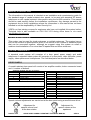
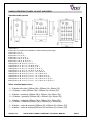
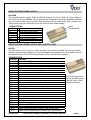
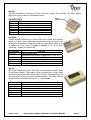
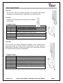
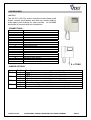
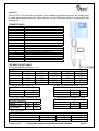
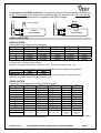
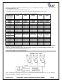
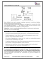
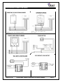
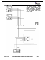
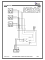
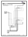
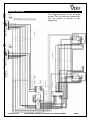
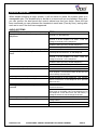
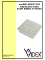
VANDAL RESISTANT
AUDIO AND VIDEO
DOOR ENTRY SYSTEMS
TECHNICAL MANUAL
EDITION 1.0
PAGE 2 of 24
AUDIO/VIDEO VANDAL RESISTANT TECHNICAL MANUAL
VER1.0
CONTENTS
Manual introduction
System introduction
System components
Vandal resistant panel layouts
Accessories
Installation
Cable size guide
Audio system block diagram
Video system block diagram
Testing the installation
Panel care
Accessories connection guide
Single entrance single button audio wiring diagram
Single entrance multiple button audio wiring diagram
Two entrance audio wiring diagram
Single entrance video system wiring diagram
Two entrance video system wiring diagram
Audio system trouble shooting guide
Video system trouble shooting guide
PAGE 3 of 24
AUDIO/VIDEO VANDAL RESISTANT TECHNICAL MANUAL
PAGE
4
4
4 – 11
5
12
12 – 14
13 – 14
14
15
15
15
16
17
18
19
20
21
22
23
VER1.0
MANUAL INTRODUCTION
The information in this manual is intended as an installation and commissioning guide for
the standard range of vandal resistant door panels, to be used with standard AC buzzer
telephones or with vandal resistant video panels using the Art.890 controller. This manual
should be read carefully before the installation commences. Any damage caused to the
equipment due to faulty installations where the information in this manual has not been
followed is not the responsibility of Videx Security Ltd.
VIDEX run free training courses for engineers who have not installed this system before.
Technical help is also available on 0191 224 3174 during office hours or via e-mail
[email protected].
SYSTEM INTRODUCTION
This system can be used for single entrances or multiple entrances. The system has no
limit on the number of apartments for which it can control or the number of entrance points
that can be connected together, although we suggest using this system on small to
medium sized installation of no more than 20 apartments and three entrances.
SYSTEM COMPONENTS
A standard audio system will comprise of a door panel, power supply and audio
telephones. A standard video system will comprise of a door panel, video controller, power
supply, video splitters and videophones. The individual parts are described below.
DOOR PANELS
A vandal resistant door panel will consist of an amplifier module, button connector board
and ‘n’ number of buttons.
Amplifier module (Art.437 or Art.537)
Connection
Function
1
Receive speech from apartment
2
Transmit speech to apartment
3
+12Vdc input
4
0V (Ground)
Camera module (Art.830 & 830C)
Connection
Function
I
+20Vdc input 200mA (400mA - 830C)
F1
0V
V
Centre core of coax video cable
M
Screen of coax video cable
SB
+8-12Vdc camera heater
Connection
LOCK
CB
A
1
2
3
4
5
6
7
8
9
10
TRADE
Connector PCB (CB)
Function
Spare connector terminals
Common of call buttons
Spare connection terminal
Call button 1 connection
Call button 2 connection
Call button 3 connection
Call button 4 connection
Call button 5 connection
Call button 6 connection
Call button 7 connection
Call button 8 connection
Call button 9 connection
Call button 10 connection
Trade button connections
Speech volume adjustments are carried out at the door panel using a small trimmer driver.
Adjustment for
speech volume level
at the door station
PAGE 4 of 24
Adjustment for
speech volume at the
apartment
AUDIO/VIDEO VANDAL RESISTANT TECHNICAL MANUAL
VER1.0
VANDAL RESISTANT PANEL LAYOUT AND SIZES
Standard audio panels
1 BUTTON = C
2 BUTTON = B, D (Note: Also available in 125mm 220mm panel style)
3 BUTTON = A, C, E
4 BUTTON = B, D, G, I
5 BUTTON = A, C, E, G, I
6 BUTTON = A, C, E, F, H, J
7 BUTTON = A, B, C, D, E, G, I
8 BUTTON = A, B, C, D, E, G, H, I
9 BUTTON = A, B, C, D, E, F, G, I, J
10 BUTTON = A, B, C, D, E, F, G, H, I, J
11 BUTTON = A, C, E, F, H, J, K, M, O, Q, S
12 BUTTON = A, C, E, F, H, J, K, M, O, P, R, T
13 BUTTON = A, C, E, F, H, J, K, M, O, P, Q, S, T
14 BUTTON = A, C, E, F, H, J, K, M, O, P, Q, R, S, T
15 BUTTON = A, B, C, D, E, F, G, H, I, J, K, L, M, N, O
16 BUTTON = A, B, C, D, E, F, G, H, I, J, K, L, M, N, O, R
17 BUTTON = A, B, C, D, E, F, G, H, I, J, K, L, M, N, O, Q, S
18 BUTTON = A, B, C, D, E, F, G, H, I, J, K, L, M, N, O, P, R, T
19 BUTTON = A, B, C, D, E, F, G, H, I, J, K, L, M, N, O, P, Q, S, T
20 BUTTON = A, B, C, D, E, F, G, H, I, J, K, L, M, N, O, P, Q, R, S, T
Other standard panel sizes:1 – 10 button with video [180mm (W) x 256mm (H) x 50mm (D)]
11 – 20 button + video [200mm (W) x 350mm (H) x 50mm (D)]
1 – 10 button + proximity [180mm (W) x 256mm (H) x 50mm (D)]
11 – 20 button + proximity [200mm (W) x 350mm (H) x 50mm (D)]
1 – 10 button + codelock [180mm (W) x 256mm (H) x 50mm (D)]
11 – 20 button + codelock [200mm (W) x 420mm (H) x 50mm (D)]
1 – 10 button + video & proximity [200mm (W) x 350mm (H) x 50mm (D)]
1 – 10 button + video & codelock [200mm (W) x 420mm (H) x 50mm (D)]
PAGE 5 of 24
AUDIO/VIDEO VANDAL RESISTANT TECHNICAL MANUAL
VER1.0
AUDIO SYSTEM POWER SUPPLY
Art.520M
The standard power supply is the Art.520M. Outputs of 12Vdc (200mA), 8Vdc (300mA)
and 13Vac (1A) are available. The dc outputs are designed to power the amplifier modules
only and can not be used to power other devices such as code locks, lock releases etc.
These items must be connected to the AC output of this power supply.
CONNECTIONS
Terminal
+12
+8
-
~
Function
12Vdc output (200mA Max.)
8Vdc output (300mA Max.)
0V (Ground)
13Vac (1A Max.)
230
0
Mains in (Live connection)
Mains in (Neutral connection)
Fuse
compartment
VIDEO SYSTEM POWER SUPPLY AND CONTROL UNIT
Art.890
The 890 control unit is used on video systems. Its functions include call tone generation,
voltage regulation and switching to both door panels and videophones, lock release control
and camera recall. The Art.890 requires both 13Vac and 24Vac to operate.
.
CONNECTIONS
Terminal Function
~&~
Power input 24Vac
~&~
Power input 13Vac
1
2
3
4
5
6
TV1
Switched 20Vdc to videophones (Only on during a call)
Switched negative from videophones to activate lock
Receive speech from videophone
Transmit speech to videophone
Ground for speech circuits
Ground for video circuits
Camera recall facility
T
A
+8
F
E
I
G2
H1
F1
F2
SE
+12V
Electronic call tone output for call buttons
13Vac output for ac lock release
8Vdc output 200mA max.
Ground for door panel speech circuits
Push button commons for AC calling
Switched 20Vdc for camera (Only on during a call)
Receive speech from door panel
Transmit speech to door panel
Negative supply for camera unit
Switched negative (Switches off when lock released)
Switched negative to lock
12Vdc output 200mA max.
V&M
V&M
Coax in from camera (V=Centre core, M=Screen)
Coax out to videophones (V=centre core, M=Screen)
PAGE 6 of 24
AUDIO/VIDEO VANDAL RESISTANT TECHNICAL MANUAL
For more information
on the Art.890 please
see the Videx Video
technical manual
VER1.0
Art.850
The 850 transformer includes a 13Vac (1A max.) output and a 24Vac (1A max.) output.
Each of the two outputs is individually fused.
CONNECTIONS
Terminal Function
24V
24V ac output
13V
13V ac output
230V
0
Live mains connection In
Neutral mains connection In
Fuse
compartment
Art. 893N
20Vdc 800mA continuous 1A surge PSU and is used as a booster
supply or when more than two videophones are required in an
apartment. This power supply only has an output when either a 0V
is applied to –C or when a voltage is applied to +C. At all other
times the + output is switched off.
Connection
230V~ 0
+
-C
+C
D+
Function
Mains voltage input
Switched 20Vdc output (Triggered by –C or +C)
0V
0V trigger input (From 4V to 0V)
+ volts trigger input (From 8V up to 30V)
Switched +20Vdc output via diode
Art.701
BST/GMT digital time clock. This time clock operates from a 12Vac
or dc power supply. The output is a dry contact relay. When used
with this system the trade button input is used. This allows the dry
contact relay to drive the lock release directly. The relay can be
programmed to release the lock for 1 – 99 seconds.
Connection
Function
+
12Vac or dc voltage input
0V
TR
Trade button input (Switched 0V)
C
Common connection on relay
NO
Normally open connection on relay
NC
Normally closed connection on relay
For more information see time clock instruction sheet
PAGE 7 of 24
AUDIO/VIDEO VANDAL RESISTANT TECHNICAL MANUAL
VER1.0
Art.502
The Art.502 is a two door
switching relay for an audio
system. One unit is required for a
two door system, one unit per door
is required for a three or more door
system. The Art.502 switches both
audio and lock release request to
the door that calls. The relay stays
latches at the last door called.
Art.892
The Art.892 is a two door
switching relay for a video system.
One unit is required for a two door
system, one unit per door is
required for a three or more door
system. The Art.892 switches
audio, video and lock release
request to the door that calls. The
relay stays latches at the last door
called.
CONNECTIONS
Connection
~
A1
A2
B1
B2
1
2
5
Current sensing path for call
from door A
Current sensing path for call
from door B
Receive speech from telephone
Transmit speech to telephone
Lock trigger from telephone
1A
1B
2B
2B
5A
5B
Transmit speech to door A
Transmit speech to door B
Receive speech from door A
Receive speech from door B
Lock trigger to door A
Lock trigger to door B
LA
LB
R
LED command (Speech open to door A)
LED command (Speech open to door B)
Reset signal (To other Art.502’s)
CONNECTIONS
Connection
1
2
3
4
5
6
R
7
8
9
10
11
12
7A
7B
8A
8B
9A
9B
10A
10B
11A
11B
12A
12B
PAGE 8 of 24
Function
0V connection from PSU
13Vac supply input
Function
13Vac supply input
0V connection
Current sensing path for call
from door A
Current sensing path for call
from door B
Reset signal (To reset other Art.892’s)
Receive speech from videophone
Transmit speech to videophone
Lock release command from Art.890
Centre core of coax to apartments
Screen of coax to apartments
Switched 20Vdc from Art.890
Transmit speech to door A
Transmit speech to door B
Receive speech from door A
Receive speech from door B
Lock trigger to door A
Lock trigger to door B
Centre core of coax from door A camera
Centre core of coax from door B camera
Screen of coax from door A camera
Screen of coax from door B camera
20Vdc to power camera at door A
20Vdc to power camera at door B
AUDIO/VIDEO VANDAL RESISTANT TECHNICAL MANUAL
VER1.0
AUDIO TELEPHONES
Art.3101
The Art.3101 AC buzzer phone includes a lock release push button
and spare dry contact push to make button for other services.
Art.3021
Smart line AC buzzer phone includes a lock release
push button.
CONNECTIONS:Function
Transmit speech to the door panel
Receive speech from the door panel
0V
Not used (Electronic call tone input)
Lock trigger (Switched 0V)
Call line (13Vac input to trigger buzzer)
Dry contact switch
1
2
3
4
5
6
8
9
5
Art.3102
The Art.3102 AC buzzer telephone includes a lock release push
button and spare dry contact push to make button for other services.
Additionally it includes a slide mute switch to turn the phone off when
the tenant does not want to be disturbed.
CONNECTIONS:1
2
3
4
5
6
8
9
Function
Transmit speech to the door panel
Receive speech from the door panel
0V
Not used
Lock Trigger (Switched 0V)
Call line (13Vac input to trigger buzzer)
Dry contact switch
5
PAGE 9 of 24
AUDIO/VIDEO VANDAL RESISTANT TECHNICAL MANUAL
VER1.0
VIDEOPHONES
Art.3311
The Art.3311 (3411 for colour) includes a lock release push
button, camera recall button and three dry contact push to
make spare push buttons for other services. An Art.3980
back plate is required with this videophone.
CONNECTIONS:1
2
3
4
5
6
7
8
9
10
11
12
13
14
15
16
17
18
Function
+12V out to power video splitter
Camera recall
Spare button
+20V power input
Door release command
Transmit speech to door panel
Receive speech from door panel
Speech Ground
Video power ground
Local call tone input
Coax centre core
Coax Screen
Speech common for intercommunicating systems
Call tone input
Speech ground for intercommunicating systems
Common of spare buttons
Spare button
Spare button
9 + COAX
JUMPER OPTIONS
Jumper Position Function
JP1
A
As a dry contact switch (Terminals 3 & 16)
B
As a camera recall button
JP2
A
S1 As a dry contact switch (Terminals 17 & 16)
B
S1 As a camera recall button
JP3
A
S2 As a dry contact switch (Terminals 18 & 16)
B
S2 As a camera recall button
JP4
A
Slave monitor (Does not switch picture on when called)
B
Master monitor (Picture switches on automatically when called)
PAGE 10 of 24
AUDIO/VIDEO VANDAL RESISTANT TECHNICAL MANUAL
VER1.0
Art.3313
The Art.3313 (3413 for colour) includes a lock release push button and two dry contact push
to make spare push buttons for other services. An Art.3980 back plate is required with this
videophone.
CONNECTIONS:1
2
3
4
5
6
7
8
9
10
11
12
13
14
15
16
17
18
Function
+12V out to power video splitter
Not used
Spare button
+20V power input
Door release command
Transmit speech to door panel
Receive speech from door panel
0V (Ground)
Not used
Local call tone input
Coax centre core or non-coax syncCoax Screen or non-coax Sync+
Switched +12 for door open LED
Select input to switch on videophone
Call tone input
Common of spare buttons
Spare button
+12V to power videophone privacy
DIP SWITCH SETTINGS
8 Way dip switch (Switches 1 – 5)
Mute Duration time
Time
1
2
15 Minutes
ON
OFF
30 Minutes
OFF
ON
2 Hours
OFF
OFF
4 Hours
OFF
OFF
8 Hours
OFF
OFF
3
OFF
OFF
ON
OFF
OFF
4
OFF
OFF
OFF
ON
OFF
5
OFF
OFF
OFF
OFF
ON
8 Way dip switch (Switch 6)
Mute LED
Switch
6
Fixed
OFF
Flashing
ON
8 Way dip switch (Switches 7 & 8)
°° Button Operation
Switch
7
8
Camera recall
ON
OFF
Dry contact
OFF
ON
4 Way Dip Switch (Switches 1 & 2)
S Button Operation
Switch
1
2
Camera recall
ON
OFF
Dry contact
OFF
ON
4 Way Dip Switch (Switches 3 & 4)
VIDEO MODE
Switch
3
4
Coax
ON
ON
Non-Coax
OFF
OFF
3 Way Dip Switch
VIDEO MODE continued
Switch
Coax
Non-Coax
PAGE 11 of 24
1
OFF
ON
2
OFF
ON
AUDIO/VIDEO VANDAL RESISTANT TECHNICAL MANUAL
3
OFF
ON
VER1.0
ACCESSORIES
Art. 512A, Art.512R
Extension sounder for an apartment. This sounder can be wall
mounted and will ring whenever the telephone it is connected to
rings. The 512A is used on video systems and the 512R is used on
AC buzzer audio systems
512A Connections
4
Call tone input
0V (Ground)
The 512R has two non-polarity
connections requiring 13Vac to
buzz
ES/1
Timed strobe unit for the hard of hearing or noisy environments.
The strobe will flash when a call is received and will continue
flashing for an adjustable time period or until the reset button is
pressed.
Connections
POWER
I/P
+O/P
GND
RESET
NC
CO
NO
12V AC or DC input
+ trigger
12Vdc output
Ground
Switched negative reset
Normally closed relay connection
Common relay connection
Normally open relay connection
INSTALLATION
The wiring diagrams towards the back of this manual should be followed carefully. Heavy
duty conductors on wiring diagrams are shown heavily outlined, These wires should be
doubled up.
-
Check that all components are free from damage before installing (Do not proceed with
installation in the event of damage).
-
Keep all packaging away from children.
-
Do not obstruct the ventilation openings or slots on any of the devices.
-
All connections to mains voltages must be made to the current national standards (IEE
Wiring regulations)
-
Install an appropriate fused spur or isolation switch to isolate the mains.
-
Isolate the mains before carrying out any maintenance work on the system.
-
All intercom and access control cables must be routed separately from the mains.
PAGE 12 of 24
AUDIO/VIDEO VANDAL RESISTANT TECHNICAL MANUAL
VER1.0
Lock release back EMF protection : A capacitor must be fitted across the terminals on
an AC lock release and a diode must be fitted across the terminals on a DC lock release
as shown in the diagrams below to suppress back EMF voltages.
~~
0.1uF capacitor
- +
-
12V AC
LOCK RELEASE
DIODE
1N4002
+
12V DC
LOCK RELEASE
CABLE SIZE GUIDE
AUDIO SYSTEM
Connections from door panel to telephone.
Connections
50m
100m
0.25mm²
0.35mm²
1
0.25mm²
0.35mm²
2
0.5mm²
0.75mm²
3
0.5mm²
0.75mm²
5
0.25mm²
0.35mm²
6
200m
0.5mm²
0.5mm²
1.5mm²
1.5mm²
0.5mm²
300m
0.75mm²
0.75mm²
2.0mm²
2.0mm²
0.75mm²
400m
1.0mm²
1.0mm²
2.5mm²
2.5mm²
1.0mm²
When ever possible connection 1(Tx) should be twisted with connection 3(Gnd) and connection 2(Rx) should
be twisted with connection 3(Gnd) as pairs.
Maximum acceptable resistance for terminals 1,2 & 6 = 10Ω and for terminals 3 & 5 = 3Ω
Connections for power supply output to door panel and lock release connections.
50m
100m
0.5mm²
0.75mm²
Connections
The power supply should be located as close to the door panel as possible for best performance.
Maximum acceptable resistance for above cables = 3Ω
VIDEO SYSTEM
Connections from door panel to the Art.890 controller.
50m
100m
200m
Connections
0.35mm²
0.5mm²
0.5mm²
T
0.5mm²
1.0mm²
1.5mm²
A
0.35mm²
0.5mm²
0.75mm²
+8
0.35mm²
0.5mm²
0.75mm²
F
0.35mm²
0.5mm²
1.0mm²
I
0.35mm²
0.35mm²
0.5mm²
G2
0.35mm²
0.5mm²
0.75mm²
H1
0.35mm²
0.5mm²
0.75mm²
F1
0.35mm²
0.5mm²
0.75mm²
F2
0.5mm²
1.0mm²
1.5mm²
SE
Standard quality
Medium quality
Good quality
V
75Ω Coax cable
75Ω Coax cable
75Ω Coax cable
M
300m
0.75mm²
2.0mm²
1.0mm²
1.0mm²
1.5mm²
0.75mm²
1.0mm²
1.0mm²
1.0mm²
2.0mm²
400m
1.0mm²
2.5mm²
1.5mm²
1.5mm²
2.0mm²
1.0mm²
1.5mm²
1.5mm²
1.5mm²
2.5mm²
Good quality
High quality
75Ω Coax
cable
75Ω Coax
cable
When ever possible connection H1(Tx) should be twisted with connection F(Gnd) and connection G2(Rx)
should be twisted with connection F(Gnd) as pairs.
PAGE 13 of 24
AUDIO/VIDEO VANDAL RESISTANT TECHNICAL MANUAL
VER1.0
Maximum acceptable resistance for terminals T, G2, H1 = 10Ω and for terminals A, +8, F, F1 & I = 6Ω and
for terminals SE & F2 = 3Ω
V is the centre core of the coax and M is the screen.
The transformer should be mounted next to the Art.890 and connected using 1mm² cores
Connections from the Art.890 controller to the videophone.
Connections
50m
100m
200m
300m
400m
Numbers in brackets are
those of the videophone
back plate. Without
brackets are signal
+12(1)
TV1(2)
TV2(3)
1(4)
2(5)
3(6)
4(7)
5(8)
6(9)
7(10)
V(11)
M(12)
R(13)
C(14)
-(15)
T(16)
1T(17)
2T(18)
0.35mm²
0.35mm²
0.35mm²
0.35mm²
0.35mm²
0.35mm²
0.35mm²
0.35mm²
0.35mm²
0.35mm²
0.35mm²
0.35mm²
0.35mm²
0.5mm²
0.35mm²
0.35mm²
0.35mm²
0.35mm²
0.5mm²
0.35mm²
0.5mm²
0.5mm²
0.5mm²
1.0mm²
0.5mm²
0.5mm²
0.5mm²
0.5mm²
1.0mm²
0.5mm²
0.75mm²
0.75mm²
0.75mm²
1.5mm²
0.75mm²
0.75mm²
0.75mm²
0.75mm²
1.5mm²
0.75mm²
1.0mm²
1.0mm²
1.0mm²
2.0mm²
1.0mm²
1.0mm²
1.0mm²
1.0mm²
2.0mm²
1.0mm²
Standard quality
Medium quality
Good quality
Good quality
High quality
75Ω Coax cable
75Ω Coax cable
75Ω Coax cable
75Ω Coax
cable
75Ω Coax
cable
0.35mm²
0.35mm²
0.35mm²
0.35mm²
0.35mm²
0.35mm²
0.35mm²
0.35mm²
0.35mm²
0.35mm²
0.35mm²
0.35mm²
0.5mm²
0.5mm²
0.5mm²
0.5mm²
0.5mm²
0.5mm²
0.75mm²
0.75mm²
0.75mm²
0.75mm²
0.75mm²
0.75mm²
1.0mm²
1.0mm²
1.0mm²
1.0mm²
1.0mm²
1.0mm²
When ever possible connection 3(6) should be twisted with connection 5(8) and connection 4(7) should be
twisted with connection 5(8) as pairs.
Maximum acceptable resistance for all terminals except 1(4) & 6(9) = 10Ω and terminals 1(4) & 6(9) = 6Ω
V is the centre core of the coax and M is the screen.
AUDIO SYSTEM BLOCK DIAGRAM
Art.3021, 3101, 3102
5
5
5
Note: Additional cores will be required for auxiliary devices such as push to exit buttons,
fireman switches, proximity access control etc.
PAGE 14 of 24
AUDIO/VIDEO VANDAL RESISTANT TECHNICAL MANUAL
VER1.0
VIDEO SYSTEM BLOCK DIAGRAM
Note: Additional cores may be required for auxiliary items such as push to exit buttons,
fireman switch proximity access control etc..
The block diagram above shows all videophones coming back to one point with all the
video distributors at that point. It is also possible to spread the video distributors around
the building (Please see wiring diagrams for more information).
Safety Note : An earth connection should also be fitted to the door panel stainless steel
facia using one of the studs provided.
TESTING THE INSTALLATION
-
Check all the connections have been made correctly and then power up the system.
-
Call all the apartments in turn. Check for call tone to the apartment, speech in both
directions, video (optional) and lock release.
-
If the volume of speech needs to be adjusted, this can be done by adjusting the presets
on the rear of the amplifier at the door panel.
-
On calltone call system only, if the call tone volume needs adjusting this can be done at
each handset (Three position slid switch on the telephone).
-
Set the time clock on/off times (Use the instructions supplied with the time clock).
Check the trade button only works when the time clock is on.
PANEL CARE
The door panels are manufactured from either 12 Gauge 304 grade stainless steel or
mirror finished brass. It is important that the facia is cleaned on regular occasions to
prevent dirt build up and tarnishing of the metal. A general household metal polish can be
used but care should be taken to follow the grain of the metal when polishing and also
avoid any polish build up around the call buttons which may prevent the buttons from
operating correctly.
PAGE 15 of 24
AUDIO/VIDEO VANDAL RESISTANT TECHNICAL MANUAL
VER1.0
ACCESSORIES CONNECTION GUIDE
3101
3101
3101
PAGE 16 of 24
AUDIO/VIDEO VANDAL RESISTANT TECHNICAL MANUAL
VER1.0
WIRING DIAGRAM
This diagram shows a single
entrance vandal resistant door
panel connected to two audio
phones in the same apartment.
The lock release shown is fail
secure 12Vac.
PAGE 17 of 24
AUDIO/VIDEO VANDAL RESISTANT TECHNICAL MANUAL
VER1.0
WIRING DIAGRAM
This diagram shows a single entrance
vandal resistant door panel connected to
multiple apartments. The lock release
shown is fail secure 12Vac. We suggest
running all telephones back to one point
(i.e. junction box next to power supply unit)
PAGE 18 of 24
AUDIO/VIDEO VANDAL RESISTANT TECHNICAL MANUAL
VER1.0
WIRING DIAGRAM
This diagram shows a two entrance
multiple apartments system. 12Vac fail
secure lock releases.
PAGE 19 of 24
AUDIO/VIDEO VANDAL RESISTANT TECHNICAL MANUAL
VER1.0
WIRING DIAGRAM
This diagram shows a single
entrance VR video door panel
connected to a single apartment with
two videophones.
PAGE 20 of 24
AUDIO/VIDEO VANDAL RESISTANT TECHNICAL MANUAL
VER1.0
WIRING DIAGRAM
This diagram shows a two entrance
system. Two VR video door panels with
two call buttons connected to two
apartments.
PAGE 21 of 24
AUDIO/VIDEO VANDAL RESISTANT TECHNICAL MANUAL
VER1.0
TROUBLE SHOOTING
When trouble shooting a large system, it will be easier to break the system down to a
manageable size. The simplest way to do this is to remove all but one handset. Doing this,
you can confirm the door panel and control cabinet are free from faults. Once this has
been confirmed you can reconnect the handsets in small sets (Floor by floor), testing after
each set to see if the fault has re-appeared.
AUDIO SYSTEMS
SYMPTOM
TEST
No speech from the door panel to the Check terminal 2 on the amplifier for continuity to
terminal 2 on the telephone.
telephone.
Before lifting the handset, check the voltage to
terminal 2 of the amplifier is 8-12Vdc. Trace this
voltage to terminal 2 to the telephone.
Check the voltage drops to approx. 1Vdc after the
handset is lifted. (If not try another telephone)
If all else fails try another amplifier at the door station
No speech from the telephone to the door Check terminal 1 on the door panel amplifier for
continuity back to terminal 1 on the telephone.
panel.
Before lifting the handset, check the voltage to on
terminal 1 of the amplifier is 8-12Vdc. Trace this
voltage to terminal 1 to the telephone.
Check the voltage drops to approx. 4Vdc after the
handset is lifted. (If not try another telephone)
If all else fails try another amplifier at the door station
No speech in either direction
Check the 315mA fuse in the power supply
Check for 12Vdc across terminals 3 & 4 on the door
panel amplifier. This should be there all the time and
comes directly from the PSU.
Lock will not operate from telephone
Check terminal 5 on the telephone. This terminal
shorts to terminal 3 of the telephone when pressed
(Becomes 0V).
Nothing happens when any call button is Check the common of the buttons has 13Vac
present at all times.
pressed
When a call button is pressed you should be able to
read 13Vac on terminals 3 & 6 of the telephone (6 of
the telephone comes direct from the call button). If
voltage is there then check/change the buzzer.
Hum on the speech lines
PAGE 22 of 24
Ensure all intercom cables do not run close to higher
voltage cables
Try another amplifier at the door panel.
AUDIO/VIDEO VANDAL RESISTANT TECHNICAL MANUAL
VER1.0
TROUBLE SHOOTING
VIDEO SYSTEMS
SYMPTOM
TEST
No call tone, Videophone works only by Check the 13Vac on the Art.850 PSU
pressing the camera recall button.
Check the wire from terminal T on the Art.890 is not
broken or short.
Try changing the Art.890
Videophone rings but picture remains off.
Check 24Vac on Art.850
Check jumper JP4 on the videophone is in position B
Check wires 1 & 6 are ok from the Art890 to the
videophone and 20Vdc is present during a call.
Try changing the Art890
Videophone red LED on but no picture
Check coax cable is not broken or short
Check Art.894 is powering up with 12Vdc during a
call. Try taking the coax straight from the camera to
a videophone.
Check for 20Vdc across the camera terminals I & F1
during a call (powered from Art890)
Picture poor
Check all end of line resistors are fitted to unused
outputs on the Art.894 and a resistor is also fitted to
the end of line.
Check for any broken coax’s or screens.
Check wire F1 & 6 is not broken and is not to small.
No Camera recall
Wire TV1 broken
Try moving the wire from TV1 into T
Hum on the speech lines
Ensure all intercom cables do not run close to higher
voltage cables
Try another amplifier at the door panel.
No audio
Check terminals 3 & 4 for 12Vdc from the Art.890
Check terminal 5 from the Art.890 to the
videophones is not broken.
No speech from videophone to door panel
Check terminals G2 and 4 on the Art.890 for
continuity back to door panel and videophone.
PAGE 23 of 24
AUDIO/VIDEO VANDAL RESISTANT TECHNICAL MANUAL
VER1.0
Northern Office
Videx Security Ltd
Unit 4-7 Chillingham Ind. Est.
Newcastle Upon Tyne
NE6 2XX
TEL 0870 300 1240
FAX 0191 224 5678
Southern Office
1 Osprey
Trinity Park
Trinity Way
London
E4 8TD
FAX 0208 523 5825
TECHNICAL SUPPORT
[email protected]
TEL 0191 224 3174
FAX 0191 224 4938
http://www.videx-security.com
PAGE 24 of 24
AUDIO/VIDEO VANDAL RESISTANT TECHNICAL MANUAL
VER1.0