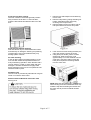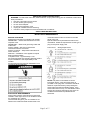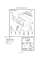
1
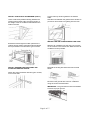
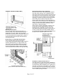
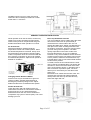
WINDOW
AIR CONDITIONER
INSTALLATION
AND
OPERATION
CATALOG NO.
WH18ZM
PRODUCT CODE
420-0075
950-0054-revB
6-29-07
Page 1 of 17
TABLE OF CONTENTS
AIR CONDITIONER SAFETY………………………………………………………………..….2
NORMAL CARE AND MAINTENANCE…………………………………………………........3
INSTALLATION REQUIREMENTS………………………………………………………........5
INSTALLATION INSTRUCTIONS………………………………………………………………6
THRU-WALL INSTALLATION INSTRUCTIONS……………………………………………11
GENERAL OPERATING INSTRUCTIONS…………………………………………………..13
OPERATING CONTROLS……………………………………………………………………..14
TROUBLESHOOTING………………………………………………………………………….15
SPECIFICATIONS………………………………………………………………………….......16
WARRANTY……………………………………………………………………………………..17
TECHNICAL SUPPORT
IF YOU NEED TECHNICAL SUPPORT, PLEASE CALL 1 (704) 504-8590 BETWEEN 8:00 AM TO 4:00 P.M.
WHEN CALLING FOR TECHNICAL SUPPORT, PLEASE HAVE COMPLETE MODEL AND SERIAL
NUMBER AVAILABLE.
AIR CONDITIONER SAFETY
Your safety and the safety of others is very important.
We have provided many important safety messages in this manual and on your appliance.
Always read and follow all safety instructions.
This is the safety alert symbol.
This symbol alerts you to potential hazards that can kill or hurt you and others.
All safety messages will follow the safety alert symbol and the word “DANGER” or
“WARNING”.
These words mean
You can be seriously injured if instructions are
not followed.
Bodily injury or damage to personal property
may occur if instructions are not followed.
All safety messages will tell you what the potential hazard is, tell you how to reduce the chance of
injury, and tell you what can happen if the instructions are not followed.
Page 2 of 17
Electrical Requirements
Grounding Instructions
This appliance is equipped with a three-prong
grounding plug for protection against possible
shock hazards. If a two-prong wall receptacle is
encountered, the customer is required to contact a
qualified electrician and have the two-prong
receptacle replaced with a properly grounded threeprong wall receptacle in accordance with the
National Electrical Code.
Room air conditioners are designed to operate
according to requirements on the nameplate and as
shown in Table 1. Do not plug models marked “Use
on Single Outlet Circuit Only” into a circuit with
another appliance or light fixture.
Installation
Complete step-by-step installation instructions are
furnished with your unit. These instructions will be
found on a separate page included with this manual
or in the mounting kit assembly. Follow these
instructions carefully. Keep these instructions with
this manual for future reference. Your unit will be
one of the following designs:
• Unit with a window mounting kit.
These models are designed for mounting through
an opening in a wall. These units can be adapted to
window installation by using the optional window
mounting kit supplied with your unit.
• Unit without a window mounting kit.
No window mounting kit is supplied with the unit.
These models are designed for mounting through
an opening in a wall. These units can be adapted to
window installation by purchasing an optional
window mounting kit. Consult your dealer to choose
the kit that is appropriate for your model and
installation.
Room Air Conditioner/Heating Units
Heat model is by electric heating elements.
See the specification sheet for electrical data
information.
Normal Care and Maintenance
Receptacle Wiring
Receptacle wiring must be of adequate size for the
unit. Refer to the unit identification plate for exact
power requirements. Minimum size of wiring, based
on power requirements, is:
Units up to 20 amps: 12 Gauge
20-30 amp units: 10 Gauge
LCDI or AFCI Power Cords
Underwriters Laboratories (UL) and the National
electric Code (NEC) now require power cords that
sense current leakage and can open the electrical
circuit to the unit. In the event the unit does not
operate, check the reset button located on or near
the head of the power cord as part of the normal
troubleshooting procedure.
Use copper wire only. The consumer’s
responsibility is to provide proper and adequate
receptacle wiring that conforms to all applicable
codes. All wiring should be installed by a qualified
electrician.
Annual Inspection
It is suggested that your unit be inspected by your
dealer or qualified technician once a year. It is
advisable to have the outer case removed and the
unit thoroughly cleaned.
NOTE: The life of your unit may be greatly reduced
if you live in a salt air or other corrosive type
environment. Under these conditions, the unit
should be removed from its case and completely
cleaned at least once a year. At that time any
scratches or blisters on the painted surfaces should
be sanded and repainted. Placing an algaecide
tablet in the outdoor side of the unit’s base is
suggested in humid areas where algae formation is
common.
Page 3 of 17
Front Grill and filter removal
The front contains a removable grill that provides
easy access to the air filter. To clean the filter,
grasp the filter handle and slide the filter out of the
unit.
Front Grill and Cabinet Cleaning
Grill and cabinet may be cleaned with warm water
and mild soap or detergent. Cleaning and polishing
compounds are not recommended as they may
damage plastic surfaces.
Air Filter Cleaning
A dirty air filter reduces operating efficiency of the
unit. The filter should be inspected at least once
every week during operation. Clean the filter with a
vacuum cleaner, or wash in warm water and mild
detergent. The filter should be thoroughly dried
before replacing in the unit. Do not operate the unit
without the filter in place.
1. Remove two side Phillips screws attaching
front to case
2. Remove inlet panel by pulling and lifting out
bottom. Reinstall air filter and grill by
reversing removal procedure.
3. Remove Phillips screws on bottom right of
inlet panel area and remove front panel.
4. If the unit has a screw holding the base pan
clip to the chassis, remove the screw.
5. Using base pan handle, pull the chassis
straight out, slowly and evenly, until
approximately 9 ½ inches extends from the
outer case. Use both hands to grasp the
base pan and pull the remaining chassis
from the outer case.
Fan Motor Care
The fan motor is permanently lubricated for long life.
There is no need to oil the motor.
Slide-out Chassis Removal from Outer Case
See Figure H.
NOTE: Base pan clip is shipped in a plastic bag
with mounting screw and condensate drain cup.
Install the clip after reinserting the chassis into
the outer case to prevent accidental chassis
removal.
Page 4 of 17
IMPORTANT SAFETY INSTRUCTIONS
WARNING: To reduce the risk of fire, electrical shock, or injury when using your air conditioner: follow these
basic precautions:
• Plug into a grounded 3 prong outlet.
• Do not remove ground prong.
• Do not use an adapter.
• Do not use an extension cord.
• Unplug air conditioner before servicing.
• Use two or more people to move and install this air conditioner.
SAVE THESE INSTRUCTIONS
INSTALLATION REQUIREMENTS
BEFORE YOU BEGIN
Read these instructions completely and carefully.
IMPORTANT – Save these instructions for local
inspector’s use.
IMPORTANT – Observe all governing codes and
ordinances.
Note to Installer – Be sure to leave these
instructions with the Consumer.
Note to Consumer – Keep these instructions for
future reference.
Skill level – Installation of this appliance require
basic mechanical skills.
Completion time – Approximately 1 hour.
We recommend that two people install this product.
Proper installation is the responsibility of the
installer.
Product failure due to improper installation is not
covered under the Warranty.
ELECTRICAL REQUIREMENTS
Ground wire must be connected to ground screw
located in lower right corner of air conditioner when
air conditioner is in cabinet.
The electrical ratings for your air conditioner are
listed on the model and serial number label. The
model and serial number is located on the side
panel of the unit.
Specific electrical requirements are listed in the
chart below. Follow the requirements for the type of
plug on the power supply cord.
Power Cord
Wiring Requirement
NOTE: The power cord includes a current
interrupter device. A test and reset button is
provided on the plug case. The device should be
tested on a periodic basis by first pressing the
TEST button and then the RESET button. If the
TEST button does not trip, or if the RESET button
will not stay engaged, discontinue use of the air
conditioner and contact a qualified service
technician.
Page 5 of 17
INSTALLATION INSTRUCTIONS
Tools you will need:
•
•
•
•
•
•
•
Adjustable Wrench
Phillips Head Screwdriver
Flat Blade Screwdriver
Pencil
Ruler or tape measure
Level
Scissors or knife
Page 6 of 17
WINDOW REQUIREMENTS
These instructions are for a standard double-hung
window. You will need to modify them for other
types of window.
The air conditioner can be installed without the
accordion panels if needed to fit in a narrow window.
See the window opening dimensions.
All supporting parts must be secured to firm wood,
masonry or metal.
The electrical outlet must be within reach of the
power cord.
REMOVE THE AIR CONDITIONER FROM THE
CASE
Remove the 2 shipping screws (if present) from the
back of the case and discard them.
Remove the locking screw and locking bracket from
the lower frame. Save to reinstall later.
Remove the ground screw and save to reinstall
later.
Slide the air conditioner from the case by gripping
the base pan handle and pulling forward while
bracing the case.
WINDOW REQUIREMENTS
A storm window frame will not allow the air
conditioner to tilt toward the outside, and will keep it
from draining properly.
To adjust for this, attach a piece of wood to the
stool.
WOOD PIECES: Width:2”
LENGTH: Long enough to fit inside the window
frame.
THICKNESS: To determine the thickness, place a
piece of wood on the stool to make it 1/2” higher
than the top of the storm window frame.
Attach securely with nails or screws provided by the
installer.
PREPARE THE WINDOW
Cut the window sash seal to the proper length. Peel
off the backing and attach the seal to the underside
of the window sash.
Page 7 of 17
PREPARE THE CASE
Install the top mounting rail with 4 type B screws
from inside the case.
Insert the frames for the accordion panels into the
top mounting rail and the bottom frame guides.
Attach the accordion panels to the side of the case
using 3 types A screws on each side.
NOTE: When attaching the accordion panels, make
sure to only screw the inner panels to the case
sides.
INSTALL THE CASE IN THE WINDOW
Carefully slide the case into the window and center
the case. Lower the window behind the top
mounting rail. Pull the bottom of the case forward
so that the bottom mounting rail is tight against the
back of the window stool. Mount the case to the
window sill using 4 type E screws. Drill pilot holes if
necessary.
Make sure the bolts and nuts are all of the way in
on both the left and right V-Supports.
Position the V-supports on the case bottom so that
they will be near the outside wall. Attach a Vsupport to each side of the bottom of the case using
3 type C screws on each side.
Adjust the leveling bolts and nuts against the
outside wall so that the case has a slight tilt to the
outside. Tighten nuts with an adjustable wrench.
Use a level; about a ½ bubble will be the correct
case slant to the outside.
Page 8 of 17
INSTALL THE CASE IN THE WINDOW (CONT.)
Use a wood block (obtained locally) between the
leveling bolts and the wall if the wall is weak or if
the weight of the air conditioner falls between the
studs in the wall.
Cut the foam top window gasket to the window
width.
Stuff the foam between the glass and the window to
prevent air and insects from getting into the room.
INSTALL THE AIR CONDITIONER IN THE CASE
Extend the left and right accordion panels to the
vertical window sashes. Drill pilot holes and attach
the top and bottom corners with 4 type D screws.
Slide the air conditioner into the case. Do not push
on the controls or the finned coils. Make sure the air
conditioner is firmly seated.
Reinstall the locking bracket and screw removed
earlier.
INSTALL SUPPORT BRACKETS AND THE
FOAM TOP WINDOW GASKET
Attach the support brackets with two type E screws,
one on each side.
Reconnect the ground wire to the air conditioner
using the screw removed earlier.
IMPORTANT: The ground wire must be reinstalled
to ensure a proper ground.
Page 9 of 17
INSTALL THE AIR CONDITIONER IN THE CASE
(CONT.)
Secure the front grill frame to the case with one
type C screw.
Remove the front grill from its box and remove the
shipping tape.
Grasp the inlet grill at the bottom corners and pull it
forward. Unhook it from its top hinges and set aside.
Using the tab, pull slightly on the filter to release it
and pull it down and out.
Pull the coiled power cord from its shipped position
in the air discharge area. Attach the front grill frame
to the case by inserting the tabs on the grill frame
into the slots on the top front of the case. Push the
grill frame in, and install the 2 side screws at bottom
left and right side of front panel.
Reinstall the filter.
Reinstall the inlet grill. Connect power.
Page 10 of 17
THRU-WALL INSTALLATION INSTRUCTIONS
INTRODUCTION
This instruction provides guidelines for installing a
compact air conditioner through an outside wall.
Air conditioner Dimensions
The following figures show the outside dimensions
of the air conditioner with the chassis installed, and
dimensions of the outer case with the chassis
removed.
Outer Case Dimensions
(Chassis removed)
General Instructions
All compact Room Air conditioners feature a slideout chassis. Chassis and front cover must be
removed from outer case for installation.
A finished opening 26 3/16” wide x 17” high is
recommended. The lower left inside corner of the
opening must be within 5 feet of an appropriate
electrical outlet.
When wall thickness exceeds 9 3/8”, the opening
must be modified to allow air to enter the side
louvers on the case (see special instructions on
back.) do not install the air conditioner in walls
thicker than 11 ¾”.
Page 11 of 17
GENERAL INSTRUCTIONS (CONT.)
Masonry Construction
See CAUTION under General Instructions. In
masonry walls, cut or build a finished opening 17”
high by 26 3/16” wide. When case is properly
positioned in opening, secure it in place with mortar
or concrete nails driven through holes in sides of
outer case (shim case and pre-drill holes before
securing with nails).
Placement of Outer Case in Opening
Place the outer case in the opening, flush against
one side of the opening. Use a carpenter’s level
and ensure case is level from side to side and has a
3/8” slope from front to back (back of case must be
3/8” lower than front to ensure proper condensate
drainage). If needed, use shims to level case (from
side to side) and to obtain proper back slope.
Front of case must project ¾” (minimum) beyond
inside wall in order to attach the air conditioner front
frame. If framing indoor side of opening with wood
molding (or other decorative materialo), extend
outer case ¾” beyond molding.
When case is properly positioned in opening, use
wood shims to fill any gaps between case and
finished opening, especially in areas where the
case will be secured to the opening. Take care not
to warp or distort the case when installing shims.
For condensate drainage, install the drainage cup in
the drain hole on the base plate of the case.
Brick Veneer or Frame Wall Construction
See CAUTION under General Instructions.
Cut or build rough opening large enough to allow a
framed, finished opening 17” high and 26 3/16”
wide. When case is properly finished in opening,
secure it in place with mortar or concrete nails
driven through holes in sides of outer case (shim
case and pre-drill holes before securing with nails).
Framed/Finished Opening
(brick veneer or fame wall construction)
Installation in Wall Thicker than 8 ½”
The side louvers in outercase provide ventilation to
air conditioner compressor and fan motor and must
not be blocked. When installing unit in a wall over 9
3/8” thick, provisions must be made in wall opening
to ensure free air flow to the side louvers. This can
be accomplished by chamfering the vertical portions
of the outside opening as shown.
Page 12 of 17
Ventilation louvers on top of case must not be
obstructed. Do not attempt to install unit in walls
thicker than 11 3/4 inches.
_________________________________________________________________________________________
GENERAL OPERATING INSTRUCTIONS
While operation of all units is similar, controls vary
slightly from model. Operating Controls section
shows control panel of unit purchased and gives
detailed information about operation of controls.
Air Around Unit
Select the highest fan speed and set the
temperature control to its coldest position. When
the desired temperature is reached, slowly move
the temperature control toward a warmer setting
until the compressor shuts off. The thermostat will
then cycle the compressor on and off to maintain
this selected temperature. Adjust the fan speed for
desired air circulation.
Changing Airflow Direction Baffles
Airflow of unit may be diverted left or right from
center by baffles. Upward and downward air
discharge is provided by tilting louvers. Adjust
baffles and tilt louvers for desired airflow pattern.
Drain Cup Installation and Use
Your air conditioner uses a system where the water
removed from the indoor air (condensate) is
channeled to the outdoor side of the unit. The
outdoor fan blade has a “slinger” ring attached to it
that dips into the water and slings the water onto
the outdoor coil surface. This is the sound of water
you hear during normal operation. The water
quickly evaporates on this warm surface and
improves the efficiency of your air conditioner.
However in very humid conditions excess amounts
of water may drip off the unit chassis. If this proves
to be a problem, install the condensate drain cup
included with the unit to route excess water where it
would not be a problem.
To install, remove the unit chassis from the outer
case. Insert the condensate drain cup through the
recessed ½” hole on the back center of the outer
case. Once inserted, place a ½” diameter hose or
tube on the drain cup bottom spout. The hose
allows you to route where you want the excess
water to go.
Reinsert the unit chassis into the outer case. The
unit base pan overflow hole will be positioned
directly above the drain cup and will catch any
water that might drain out.
Airflow Around Unit
Check the indoor grill and outdoor louvers for
obstructions to air flow. Do not block the airflow to
and from the unit. If air is obstructed and/or
deflected back into the unit, the air conditioner’s
compressor may cycle on and off rapidly. This could
damage your unit.
Page 13 of 17
OPERATING CONTROLS
Fan Control
OFF Completely shuts off the unit. To prevent
blowing fuses, wait two minutes after turning the
unit off before turning it on again.
LOW COOL Filters and circulates room air with the
fan running continuously on low speed. Also cools
and dehumidifies while the compressor is running.
Select this setting for quiet cooling operation
HIGH COOL Filters and circulates room air with the
fan running continuously on high speed. Also cools
and dehumidifies while the compressor is running.
Select this setting for maximum air circulation and
cooling effect.
LOW HEAT Filters and circulates room air with the
fan running continuously on low sp-eed. Also heats
while the compressor or electric heat is running.
Select this setting for quiet heating operation.
HIGH HEAT Filters and circulates room air with the
fan running continuously on high speed. Also heats
while the compressor or electric heater is running.
Select this setting for maximum air circulation and
heating effect.
FAN ONLY Select this setting for circulating or
exhausting room air without heating or cooling.
Temperature Control
Turn this control to the left for a warmer room
temperature, to the right for a cooler room
temperature.
Vent Control (On Some Models)
Choose one of the following two settings by sliding
the vent control under the appropriate marking:
• EXHAUST Exhausts room air to the
outdoors. Also circulates and filters room
air. This position can be used to exhaust
stale or smoky air. To conserve energy, it is
advised that the Fan Control be in the Fan
Only setting when using this feature.
• CLOSED Exhaust damper is closed. Unit
circulates and filters room air. This position
should be used for normal cooling
operation.
Circulair
This control allows you to circulate the air across
the room. When in the ON position, vertical louvers
in the air outlet grill are moved back and forth
distributing the air throughout the room. When in
the OFF position, the vertical louvers in the air
outlet remain pointed in the direction they were
when the switch was moved to the OFF position.
Page 14 of 17
TROUBLESHOOTING
The following is a list of problems that are sometimes encountered when using a room air conditioner. Possible
cause and suggested remedies are given for each problem.
• UNIT WILL NOT RUN
Push reset button on power cord.
Set Fan Control to position other than OFF.
Make sure plug is firmly seated in outlet.
Check for blown fuses, tripped circuit breakers.
•
LITTLE OR NO COOLING / LITTLE OR
NO HEATING (fan and compressor run)
Set vent to CLOSED
Remove obstruction from indoor grill or outdoor
louvers.
Dirty air filter. Clean or replace as needed.
Check with dealer to determine proper capacity
unit for application.
Page 15 of 17
• NOISY UNIT
Tighten any loose parts.
Provide additional support for unit.
Normal in high humidity. Stop noise by
removing drain plug or adding condensate drain
cup.
Check with dealer to determine proper capacity
unit for application.
• MOUNTING SUPPORT NOT INSTALLED
Some models require removal of storm window
frame before installation.
• FROST ON INDOOR COIL
Clean air filter by vacuuming or washing with
water and mild soap.
Turn Temperature Control to warmer setting
reduces occurrence and duration of frost.
TECHNICAL SPECIFICATIONS
MODEL
BTU COOLING
BTU HEATING
EER RATING
DEHUMIDIFICATION (pints/hour)
AIRFLOW (CFM)
VOLTAGE
FREQUENCY
AMPS COOLING
AMPS HEATING
WATTS COOLING
WATTS HEATING
PLUG TYPE
POWER CORD RATING (amps)
POWER CORD TYPE
POWER CORD LENGTH
REFRIGERANT
REFRIGERANT CHARGE (oz. / lbs )
SOUND (INSIDE/OUTSIDE) dba (MAX)
4 WAY AIR ADJUSTMENT
2 WAY AIR SWING
AIR DISCHARGE
MOTOR TYHPE
MOTOR CAPACITOR
CONTROLS
THERMOSTAT TEMP °F
CABINET SIZE (INCHES)
WIDTH
DEPTH
HEIGHT
WINDOW OPENING WIDTH
THRU WALL MAX THICKNESS
WEIGHT (lbs.) (Gross / Net)
APPROVALS
TABLE 1
Page 16 of 17
WH18ZM
18,000 – 17,600
11,000 – 8,600
9.7
4.2
450 (MAX)
230 – 208 VAC
60 HZ
8.2 – 8.75
15.4 – 13.93
1885 – 1850
3500
TYPE C
20
LCDI
6’
R22
27.84 / 1.74
59 / 63
YES
YES
SIDE
BALL BEARING
7 µfd
MECHANICAL
61°F to 89°F
26”
27 7/8”
16 7/8”
30 – 46”
8.5”
163 / 150
UL/CUL
WARRANTY
International Refrigeration Products warrants the she product supplied is free from defects in material and
workmanship. This warranty is valid as long as this product is properly handled, installed, operated and
serviced in accordance with the Installation and Operating Instructions shipped with this unit, and warranty
card is completed and mailed no later than 30 days after date of purchase. All warranty claims must be
made within one (1) year (five (5) years for compressor) from date of purchase (unless national regulations
require a longer registration period).
This warranty provides free replacement of defective parts only. Labor, Service calls, and replacement parts
as a result of normal wear and tear are not covered under this warranty.
Additional claims are excluded, unless required by national regulations. International Refrigeration Products
inc. is not responsible for incidental, consequential, direct, or indirect damage or expenses relating to the
use of, or the inability to use he product for any purpose. Other implied warranties are excluded.
This constitutes International Refrigeration Products warranty obligation and replaces any and all prior
warranties for this product.
INTERNATIONAL REFRIGERATION PRODUCTS INC.
11325 Nations Ford Rd. Charlotte, NC 28134-8393
(704) 504-8590 Phone (704) 504-3023 Fax
Copyright 2006 IRP INC.
950-0054
Page 17 of 17