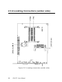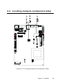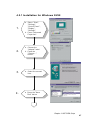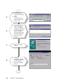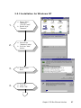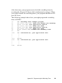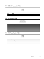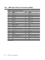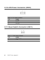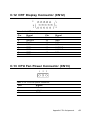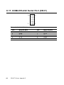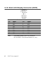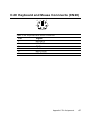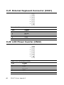
1
PCI-6771 series
Socket 370 Pentium® III/Celeron™
Half-size Card PC with High Speed
PCI Bus, 3D LCD and Ethernet
Copyright Notice
This document is copyrighted, 1999. All rights are reserved. The
original manufacturer reserves the right to make improvements to the
products described in this manual at any time without notice.
No part of this manual may be reproduced, copied, translated or
transmitted in any form or by any means without the prior written
permission of the original manufacturer. Information provided in this
manual is intended to be accurate and reliable. However, the original
manufacturer assumes no responsibility for its use, nor for any
infringements upon the rights of third parties which may result from
its use.
Acknowledgements
Award is a trademark of Award Software International, Inc.
IBM, PC/AT, PS/2 and VGA are trademarks of International Business
Machines Corporation.
Intel and Pentium are trademarks of Intel Corporation.
Microsoft Windows® is a registered trademark of Microsoft Corp.
UMC is a trademark of United Microelectronics Corporation.
All other product names or trademarks are properties of their
respective owners.
For more information on this and other Advantech products please
visit our website at: http://www.advantech.com
http://www.advantech.com/epc
For technical support and service for please visit our support website
at: http://www.advantech.com/support
This manual is for the PCI-6771 Series Rev. A1 and B1
Part No. 2006677101
Printed in Taiwan
PCI-6771User's Manual
2nd Edition
May 2000
1.2 Specifications
Standard SBC functions
• CPU: Socket 370 for Intel® Pentium III processors up to 650
MHz or higher in the future (Rev. B1 only) and Celeron™
processor up to 500 MHz
• BIOS: 2/4 Mbit Flash BIOS, supports Plug & Play, APM 1.2
Support Ethernet Boot ROM
Support boot from CD-ROM
Support boot from LS-120 ZIP™ Drive
Optional Customer icon
• Chipset: Intel® 440BX PCI set, FSB 66/100 MHz
• 2nd level cache: 256 KB on Pentium III or 128 KB on Celeron™
Processor
• System memory: Two SODIMM sockets, support 8 MB to 256
MB, accepts 8/16/32/64/128 MB Synchronous DRAM
• PCI IDE interface: One Enhanced IDE interface, supports 2
IDE devices PIO mode 3,4 with bus mastering up to 14 MB/sec.
Ultra DMA model up to 33 MB/sec.
• Floppy disk drive interface: Supports up to two FDDs (360
KB/1.2 MB/720 KB/1.44 MB/2.88 MB)
• Parallel port: One parallel port, supports EPP/ECP
• IR port: One 115 kbps IrDA compliant serial infrared
• Serial ports: 2 serial ports
COM1: RS-232, COM2: RS-232/422/485
• Watchdog timer: 62 levels timer interval, setup by software,
jumperless selection, generates system reset or IRQ11
Chapter 1 General Information
3
Contents
Chapter 1 General Information ........................................ 1
1.1
1.2
1.3
1.4
Introduction ............................................................................. 2
Specifications .......................................................................... 3
Features ................................................................................... 5
Board layout: Dimensions ...................................................... 6
Chapter 2 Installation ........................................................ 7
2.1 Safety Precautions ...................................................................... 8
2.2 Jumpers ................................................................................... 9
2.3 Connectors ............................................................................ 10
2.3.1 Locating connectors .................................................. 11
2.3.2 Locating Connectors (solder side) ............................. 12
2.4 Locating Jumpers (component side) .................................... 13
2.5 Setting jumpers .................................................................... 14
2.6 CMOS clear function (JP1) ................................................. 15
2.7 Watchdog timer config. (JP2) .............................................. 16
2.8 COM2 settings for RS-232/422/485 (JP3) .............................. 17
2.9 Power type select (JP4) ........................................................ 17
2.10 LCD Panel select (SW1) ...................................................... 18
2.11 Installation Caution ................................................................. 19
2.12 USB Connector (CN1) .......................................................... 20
2.13 Parallel Port Connector (CN2) ............................................ 20
2.14 Hard disk drive LED (CN3) .................................................. 21
2.15 IR Connector (CN4) .............................................................. 21
2.16 ATX power button (CN5) ....................................................... 21
2.17 Keyboard Lock (CN6) ........................................................... 21
2.18 External Speaker (CN7) ....................................................... 22
2.19 Enhanced IDE Connector (CN8) ........................................... 22
2.20 Floppy Drive Connector (CN9) ............................................. 23
2.21 ATX Feature Connector (CN10) .......................................... 23
2.22 Reset switch (CN11) ............................................................. 24
2.23 VGA Display Connector (CN12) .......................................... 24
2.24 CPU Fan Power Supply Connector (CN13) .......................... 24
PCI-6771User's Manual
2.25
2.26
2.27
2.28
2.29
2.30
2.31
2.32
2.33
2.34
2.35
Ethernet Configuration (CN14) ........................................... 25
RS-232 connection (COM1-CN15) ...................................... 25
RS-232/422/485 connection
Flat panel Display Connector (CN18) .................................. 26
Ext.flat panel Display Connector(CN19) .............................. 27
Keyboard & PS/2 Mouse Connector (CN20) ....................... 27
External Keyboard (CN21) .................................................... 27
LCD Inverter Connector (CN22) .......................................... 27
AT Power Connector (CN23) ................................................ 28
CompactFlash Disk (CN24) .................................................. 28
Installing System Memory (SODIMMs) .............................. 28
2.35.1 Installing SODIMMs .................................................... 28
2.36 CPU installation and upgrading ........................................... 30
CHAPTER 3 Award Bios Setup ....................................... 31
3.1 AWARD BIOS Setup ................................................................ 32
3.1.1 Entering setup ............................................................... 32
3.1.2 Standard CMOS setup .................................................. 33
3.1.3 BIOS features setup ...................................................... 34
3.1.4 CHIPSET features setup ................................................ 38
3.1.5 Power management setup .............................................. 39
3.1.6 PnP PCI configuration setup ......................................... 40
3.1.7 Load BIOS defaults ....................................................... 40
3.1.8 Load setup defaults ....................................................... 40
3.1.9 Integrated Peripherals ................................................... 41
3.1.10 Password setting ......................................................... 41
3.1.11 IDE HDD auto detection .............................................. 42
3.1.12 Save & exit setup ......................................................... 42
3.1.13 Exit without saving ...................................................... 42
AGP SVGA Setup .............................................................. 43
4.1
4.2
Introduction ........................................................................... 44
4.1.1 Chipset ........................................................................... 44
4.1.2 Display memory .............................................................. 44
4.1.3 Display types ................................................................. 44
4.1.4 Dual/simultaneous display ............................................. 45
Installation of SVGA driver .................................................. 46
Preface and Table of Contents
4.3
4.2.1 Installation for Windows 95/98 ...................................... 47
4.2.2 Installation for Windows NT .......................................... 50
Further information .............................................................. 52
Chapter 5 PCI Bus Ethernet Interface .......................... 53
5.1
5.2
5.3
Introduction ........................................................................... 54
Installation of Ethernet driver .............................................. 54
5.2.1 Installation for MS-DOS and Windows 3.1 .................... 54
5.2.2 Installation for Windows 95/98 ...................................... 55
5.2.3 Installation for Windows NT .......................................... 57
Further information .............................................................. 59
Programming the Watchdog Timer ................................. 61
APPENDIX A Programming the Watchdog Timer ......... 61
A.1
Programming the Watchdog Timer ..................................... 62
Appendix C Pin Assignments ......................................... 65
C.1
C.2
C.3
C.4
C.5
C.6
C.7
C.8
C.9
C.10
C.11
C.12
C.13
C.15
C.16
C.17
C.18
C.19
C.20
C.23
C.22
USB1/USB2 Connector (CN1) ............................................. 66
Parallel Port Connector (CN2) ............................................ 66
HDD LED Connector (CN3) .................................................. 67
IR Connector (CN4) .............................................................. 67
ATX Power Switch (CN5) ..................................................... 67
Keyboard Lock Connector (CN6) ......................................... 68
External Speaker Connector (CN7) ..................................... 68
IDE Hard Drive Connector (CN8) ......................................... 69
Floppy Drive Connector (CN9) ............................................. 69
ATX Power Connector (CN10) ............................................. 70
Reset Switch Connector (CN11) .......................................... 70
CRT Display Connector (CN12) .......................................... 70
CPU Fan Power Connector (CN13) ...................................... 71
COM1 RS-232 Serial Port (CN15) ...................................... 71
COM2 RS-422/485 Serial Port (CN16) .............................. 72
COM2 RS-232 Serial Port (CN17) ...................................... 72
24-bit LCD Display Connector (CN18) ................................ 73
36-bit LCD Display Connector (CN19) ................................ 74
Keyboard and Mouse Connnecto (CN20) .............................. 74
AT Power Connector (CN23) ................................................ 75
LCD Power Inverter (CN22) ................................................ 75
PCI-6771User's Manual
C.21 External Keyboard Connector (CN21) ................................. 75
C.24 CompactFlash Card Connector (CN24) ............................... 76
Appendix D System Assignments .................................. 77
D.1
D.2
D.3
D.4
System I/O Ports .................................................................. 78
DMA Channel Assignments ................................................. 79
Interrupt Assignments ......................................................... 79
1st MB Memory Map ............................................................ 80
Tables
Table 2-1: Jumpers .......................................................................................... 9
Table 2-2: Connectors .................................................................................... 10
Table 2-3: RTC power and CMOS clear (JP1) ................................................ 15
Table 2-4: Watchdog timer system reset select (JP2) .................................... 16
Table 2-5: COM2 settings for RS-232/422/485 (JP3) .................................... 17
Table 2-6: Power type select (JP4) ................................................................. 17
Table 2-7: Panel Type Select (SW1) .............................................................. 18
Table 2-10: PCI-6771 serial port default settings .......................................... 26
Table C-1: USB1/USB2 connector .................................................................. 66
Table C-2: Parallel port connector .................................................................. 66
Table C-3: HDD LED connector ...................................................................... 67
Table C-4: IR connector .................................................................................. 67
Table C-5:ATX power switch ........................................................................... 67
Table C-6: Keyboard lock connector .............................................................. 68
Table C-7: External speaker connector ........................................................... 68
Table C-8: IDE hard drive connector .............................................................. 69
Table C-9: Floppy drive connector ................................................................. 69
Table C-10: ATX power connector .................................................................. 70
Table C-11: Reset switch connector .............................................................. 70
Table C-12: CRT display connector ................................................................ 70
Table C-13: CPU fan power connector ........................................................... 71
Preface and Table of Contents
Table C-15: COM1 RS-232 serial port ............................................................. 71
Table C-16: COM2 RS-232/422/485 serial port ............................................. 72
Table C-17: COM2 RS-232 serial port ............................................................. 72
Table C-5: 24-bit LCD display connector ....................................................... 73
Table C-19: 36-bit LCD display connector ..................................................... 74
Table C-20: Keyboard and mouse connector ................................................. 74
Table C-23: AT power connector .................................................................... 75
Table C-22: LCD power inverter ...................................................................... 75
Table C-21: External keyboard connector ...................................................... 75
Table C-24: CompactFlash card connector .................................................... 76
Table D-1: System I/O ports ........................................................................... 78
Table D-2: DMA channel assignments ........................................................... 79
Table D-3: Interrupt assignments .................................................................. 79
Table D-4:1st MB memory map ...................................................................... 80
Figures
Figure 1-1: PCA-6771 board layout Dimensions ............................................. 5
Figure 2-1: Locating connectors (component side) ...................................... 11
Figure 2-2: Locating connectors (solder side) .............................................. 12
Figure 2-3: Locating jumpers (component side) ........................................... 13
Figure 2-4: ATX adaptor cable ........................................................................ 23
Figure 2-5: SODIMM dimensions ................................................................... 29
Figure 3-1: Setup program initial screen ....................................................... 32
Figure 3-2: CMOS setup screen ..................................................................... 33
Figure 3-3: BIOS features setup screen ......................................................... 34
Figure 3-4: CHIPSET features setup screen .................................................. 38
Figure 3-5: Power management setup screen .............................................. 39
Figure 3-6: PCI configuration screen ............................................................ 40
Figure 3-7: Integrated peripherals ................................................................ 41
Figure 3-8: Exiting ......................................................................................... 42
PCI-6771User's Manual
Preface and Table of Contents
CHAPTER
1
General Information
This chapter gives background information
on the PCI-6771.
Sections include:
• Introduction
• Features
• Specifications
• Board layout and dimensions
1.1 Introduction
The PCI-6771 all-in-one industrial grade PCI-bus CPU card uses
Intel’s highly acclaimed Celeron® processor or Pentium® III
processor, together with the Intel 440BX PCI chipset.
The CPU provides 128 KB (or 256 KB for Pentium III) on-CPU
L2 cache, eliminating the need for external SRAM chips. It has
one PCI EIDE interface for up to two devices and a floppy disk
drive interface for up to two devices. Other features include two
RS-232 serial ports (16C550 UARTs with 16-byte FIFO or
compatible), one enhanced parallel port (supports SPP/EPP/ECP)
and one USB (Universal Serial Bus) port. The PCI enhanced IDE
controller supports Ultra DMA/33 and PIO Mode 4 operation.
This provides data transfer rates of over 33 MB/sec. System Bios
supports boot-up from an IDE CD-ROM, SCSI CD-ROM and LS120.
A backup of CMOS data is stored in the Flash memory, which
protects data even after a battery failure. Also included is a 62level Watchdog timer which resets the CPU or generates an
interrupt if a program cannot be executed normally. This enables
reliable operation in unattended environments.
The PCI-6771 offers several impressive industrial features such as
VGA (AGP) controller, two SODIMM slots for a total of 256 MB
RAM memory and a 10/100Base-T networking controller. In
addition, the PCI-6771 series supports a solid state disk (SSD)
using a CompactFlash™ disk that is not as vulnerable to the
hazards of an industrial computing environment. These features
make it an ideal choice for applications that require both high
performance and full functionality.
2
PCI-6771 User's Manual
1.2 Specifications
Standard SBC functions
• CPU: Socket 370 for Intel® Pentium III processors up to 650
MHz or higher in the future (Rev. B1 only) and Celeron™
processor up to 500 MHz
• BIOS: 2/4 Mbit Flash BIOS, supports Plug & Play, APM 1.2
Support Ethernet Boot ROM
Support boot from CD-ROM
Support boot from LS-120 ZIP™ Drive
Optional Customer icon
• Chipset: Intel® 440BX PCI set, FSB 66/100 MHz
• 2nd level cache: 256 KB on Pentium III or 128 KB on Celeron™
Processor
• System memory: Two SODIMM sockets, support 8 MB to 256
MB, accepts 8/16/32/64/128 MB Synchronous DRAM
• PCI IDE interface: One Enhanced IDE interface, supports 2
IDE devices PIO mode 3,4 with bus mastering up to 14 MB/sec.
Ultra DMA model up to 33 MB/sec.
• Floppy disk drive interface: Supports up to two FDDs (360
• IR port: One 115 kbps IrDA compliant serial infrared
• Serial ports: 2 serial ports
COM1: RS-232, COM2: RS-232/422/485
• Watchdog timer: 62 levels timer interval, setup by software,
jumperless selection, generates system reset or IRQ11
Chapter 1 General Information
3
• Parallel port: One parallel port, supports EPP/ECP
VGA function
AGP SVGA/Flat Panel Interface
• Chipset: Trident™ Cyber 9525 DVD, high performance 64-bit
GUI, 3D engine
• Display memory: 2.5 MB of SDRAM frame buffer on cyber
9525DVD. (with optional 8 MB)
• Display type: Simultaneously supports CRT and flat panel
(EL, LCD and gas plasma) displays
• Interface: 2x AGP, Accelerator Graphics Ports 1.0 compliant
• Display mode:
LCD panel supports up to 800 x 600 @ 24 bpp, 1024 x 768 @
24 bpp.
CRT display supports up to 800 x 600 @ 24 bpp, 1024 x 768
@ 24 bpp
Ethernet controller functions
• RealTek™ RTL 8139 chip
PCI Ethernet controller, IEEE 802.3 protocol compatible
Supports 10/100 Mbps Base-T
Solid state disk
• Supports CompactFlash™ disks
4
PCI-6771 User's Manual
Mechanical and environmental specifications
• Standard Mode Power Consumption
4.73 A @ 5 V with Celeron™ 466, 128 MB SO DIMM
• Operating temperature:
0 ~ 60° C (32 ~ 140° F)
• Size: 185 mm x 122 mm
• Weight: 0.26 kg
1.3 Features
• Supports Socket 370 for Intel® Pentium® III/Celeron™
processor
• AGP 3D VGA/LCD and supports 36 bit XGA TFT LCD Panel
• USB interface compliant with USB rev. 1.0
• SIR support
• System overheat temperature control
• 62-levels Watchdog timer, jumperless on-line setup supported
• Supports wake-up on LAN, Modem
• Supports turn off LCD back light function
• Supports PCI interface compliant with PCI rev. 2.1
• Supports four PCI Bus masters
Chapter 1 General Information
5
1.4 Board layout: Dimensions
Figure 1-1: PCI-6771 (dimensions)
6
PCI-6771 User's Manual
CHAPTER
2
Installation
This chapter tells how to set up the
PCI-6771 hardware. It includes instructions
on setting jumpers, and connecting
peripherals, switches and indicators. Be
sure to read all the safety precautions before
you begin the installation procedure.
2.1 Safety Precautions
Follow these simple precautions to protect yourself from harm and
your PC from damage.
1. To avoid electric shock, always disconnect the power from your
PC chassis before you work on it. Don't touch any components on
the CPU card or other cards while the PC is on.
2. Disconnect power before making any configuration changes. The
sudden rush of power as you connect a jumper or install a card
may damage sensitive electronic components.
3. Always ground yourself to remove any static charge before you touch
your CPU card. Be particularly careful not to touch the chip
connectors. Modern integrated electronic devices, especially CPUs
and memory chips, are extremely sensitive to static electric discharges
and fields. Keep the card in its antistatic packaging when it is not
installed in the PC, and place it on a static dissipative mat when you are
working with it. Wear a grounding wrist strap for continuous
protection.
2.2 Jumpers
The PCI-6771 has a number of jumpers that allow you to configure
your system to suit your application. The table below lists the
function of each of the board’s jumpers.
Table
Label
JP1
2-1:
Jumpers
Function
CMOS clear
JP2
Watchdog timer action
JP3
COM2 RS-232/422/485 setting
JP4
Power type select
SW1
Panel type select
Chapter 2 Installation
9
2.3 Connectors
On-board connectors link the PCI-6771 to external devices such as
hard disk drives, a keyboard, or floppy drives. The table below
lists the function of each of the board’s connectors.
10
Table
2-2:
Label
Function
C onnectors
CN1
USB channel 1, 2 connector
CN2
Parallel port connector
CN3
External IDE LED
CN4
IR connector
CN5
ATX power switch button
CN6
Keyboard Lock connector
CN7
Speaker connector
CN8
IDE hard drive connector
CN9
Floppy drive connector
CN10
ATX feature connector
CN11
Reset connector
CN12
CRT display connector
CN13
Fan power connector
CN14
Ethernet 100/10Base-T connector
CN15
COM1, 232 connector
CN16
COM2, 422/485 connector
CN17
COM2, 232 connector
CN18
Flat panel connector
CN19
Ext. flat panel display connector
CN20
Keyboard and PS/2 mouse connector
CN21
EXT keyboard connector
CN22
LCD inverter power
CN23
Main power connector
CN24
CFC connector
PCI-6771 User's Manual
2.3.1 Locating connectors
Figure 2-1: Locating connectors (component side)
Chapter 2 Installation
11
2.3.2 Locating Connectors (solder side)
Figure 2-2: Locating connectors (solder side)
12
PCI-6771 User's Manual
2.4 Locating Jumpers (component side)
Figure 2-3: Locating jumpers (component side)
Chapter 2 Installation
13
2.5 Setting jumpers
You configure your card to match the needs of your application by
setting jumpers. A jumper is the simplest kind of electric switch. It
consists of two metal pins and a small metal clip (often protected
by a plastic cover) that slides over the pins to connect them. To
“close” a jumper, connect the pins with the clip. To “open” a
jumper, remove the clip. Sometimes a jumper will have three pins,
labeled 1, 2, and 3. In this case, you would connect either pins 1
and 2 or 2 and 3.
1
Open
Closed
2
3
Closed 2-3
The jumper settings are schematically depicted in this manual as
follows:
1
Open
Closed
Closed 2-3
A pair of needle-nose pliers may be helpful when working with
jumpers. Setting switches is slightly different but more simple.
Simply slide the desired switch to the on or off position. In the
example below, the 6 element switch would be. 1:off, 2:on, 3:off,
4:off, 5:off, 6:off.
On
Off
1 2 3 4 5 6
If you have any doubts about the best hardware configuration for
your application, contact your local distributor or sales rep
14
PCI-6771 User's Manual
2.6 CMOS clear function (JP1)
Warning:
Table
2-3:
To avoid damaging the computer, always turn off
the power supply before setting "Clear CMOS".
Set the jumper back to normal before turning on
the power supply.
RTC
power
and
*Normal
1
CMOS
clear
(JP1)
CMOS data clear
1
JP1
* default setting
Chapter 2 Installation
15
2.7
Watchdog timer config. (JP2)
An on-board watchdog timer reduces the chance of disruptions which
EMP (electro-magnetic pulse) interference can cause. This is an
invaluable protective device for standalone or unmanned
applications. Setup involves two jumpers and running the control
software. (Refer to Appendix A.)
When the watchdog timer is enabled and the CPU shuts down, the
watchdog timer will automatically either reset the system or
generate an interrupt on IRQ 11, depending on the setting of
jumper JP2, as shown below:
Table
2-4:
Watc hdog
timer
sys tem
*System Reset
1
JP2
* default setting
16
PCI-6771 User's Manual
reset
select
(JP2)
IRQ 11 interrupt
1
2.8 COM2 settings for RS-232/422/485 (JP3)
Table
2-5:
COM2
settings
for
RS-232/422/485
*RS-232
JP3
(JP3)
RS-422
RS-485
1
2
1
2
1
2
3
4
3
4
3
4
5
6
5
6
5
6
* default setting
2.9 Power type select (JP4)
Table
2-6:
Po wer
t ype
select
ATX Power
1
(JP4)
*AT Power
1
JP4
* default setting
Chapter 2 Installation
17
2.10 LCD Panel select (SW1)
Table
2-7:
P anel
T ype
Select
Display
(S W1)
TYPE
Setting (SW1)
On
640 x 480
18 bits TFT
Off
1 2 3 4 5 6
800 x 600
18 bits TFT
On
Off
1 2 3 4 5 6
1024 x 768
24 bits TFT
On
Off
1 2 3 4 5 6
On
1024 x 768
36 bits TFT
Off
1 2 3 4 5 6
On
640 x 480
16 bits STN
Off
1 2 3 4 5 6
On
800 x 600
16 bits STN
Off
1 2 3 4 5 6
On
1024 x 768
16 bits STN
Off
1 2 3 4 5 6
1024 x 768
24 bits STN
On
Off
1 2 3 4 5 6
* Please Note: Pin 6 is extra, please disregard!
18
PCI-6771 User's Manual
2.11 Installation Caution
The following sections tell how to make each connection. In most
cases, you will simply need to connect a standard cable. All of the
connector pin assignments are shown in Appendix C.
Warning! Always completely disconnect the power cord
from your chassis whenever you are working on
it. Do not make connections while the power is
on. Sensitive electronic components can be
damaged by a sudden rush of power. Only
experienced electronics personnel should open
the PC chassis.
Caution! Always ground yourself to remove any static
charge before touching the CPU card. Modern
electronic devices are very sensitive to static
electric charges. Use a grounding wrist strap at
all times. Place all electronic components on a
static-dissipative surface or in a static-shielded
bag when they are not in the chassis.
Chapter 2 Installation
19
2.12 USB Connector (CN1)
The PCI-6771 board provides two USB (Universal Serial Bus)
interfaces, which give complete plug and play and also hot
attach/detach for up to 127 external devices. The USB interfaces
comply with USB specification rev. 1.0 and are fuse protected.
The USB interfaces are accessed through a 10-pin flat-cable
connector, CN1. The adapter cable has a 10-pin connector on one
end and a USB connector on the bracket.
The USB interfaces can be disabled in the system BIOS setup.
2.13 Parallel Port Connector (CN2)
The parallel port is normally used to connect the CPU card to a
printer. The PCI-6771 includes an on-board parallel port, accessed
through a 26-pin flat-cable connector, CN2. The card comes with
an adapter cable which lets you use a traditional DB-25 connector.
The cable has a 26-pin connector on one end and a DB-25
connector on the other, mounted on a retaining bracket. The
bracket installs at the end of an empty slot in your chassis, giving
you access to the connector.
The parallel port is designated as LPT1, and can be disabled or
changed to LPT2 or LPT3 in the system BIOS setup.
To install the bracket, find an empty slot in your chassis. Unscrew
the plate that covers the end of the slot. Screw in the bracket in
place of the plate. Next, attach the flat-cable connector to CN2 on
the CPU card. Wire 1 of the cable is red or blue, and the other
wires are gray. Make sure that wire 1 corresponds to pin 1 of CN2.
Pin 1 is on the right side of CN2.
20
PCI-6771 User's Manual
2.14 Hard disk drive LED (CN3)
You can connect an LED to connector CN3 to indicate
when the HDD is active. Marks on the circuit board
indicate LED polarity.
2.15 IR Connector (CN4)
This connector supports the optional wireless infrared
transmitting and receiving module. This module mounts on
the system case. You must configure the setting through
BIOS setup.
2.16 ATX power button (CN5)
The PCI-6771 provides an ATX power input connector.
When connected with the ATX power switch, the ATX
power switch connector (CN5) enables power On/Off from
the chassis.
2.17 Keyboard Lock (CN6)
Connecting CN6 enables the keyboard locking function
from the front panel of your chassis.
Chapter 2 Installation
21
2.18 External Speaker (CN7)
Connect external speakers to CN7. To activate the on-board
buzzer, set the connector so that Pins 3 and 4 are closed.
2.19 Enhanced IDE Connector (CN8)
You can attach two IDE (Integrated Device Electronics) drives to
the PCI-6771’s internal controller. The PCI-6771 CPU card has an
EIDE connector, CN8.
Wire number 1 on the cable is red or blue, and the other wires are
gray. Connect one end to connector CN8 on the CPU card. Make
sure that the red (or blue) wire corresponds to pin 1 on the
connector (on the right side). See Chapter 1 for help in finding the
connector.
Unlike floppy drives, IDE hard drives can connect in either
position on the cable. If you install two drives, you will need to set
one as the master and one as the slave. You do this by setting the
jumpers on the drives. If you use just one drive, you should set it
as the master. See the documentation that came with your drive for
more information.
Connect the first hard drive to the other end of the cable. Wire 1
on the cable should also connect to pin 1 on the hard drive
connector, which is labeled on the drive circuit board. Check the
documentation that came with the drive for more information.
Connect the second drive, as described above, on CN8.
22
PCI-6771 User's Manual
2.20 Floppy Drive Connector (CN9)
You can attach up to two floppy disk drives to the PCI-6771’s onboard controller. You can use any combination of 5.25" (360 KB/
1.2 MB) and/or 3.5" (720 KB/1.44/2.88 MB) drives.
The card comes with a 34-pin daisy-chain drive connector cable.
On one end of the cable is a 34-pin flat-cable connector. On the
other end are two sets of floppy disk drive connectors. Each set
consists of a 34-pin flat-cable connector (usually used for 3.5"
drives) and a printed-circuit-board connector (usually used for
5.25" drives). You can use only one connector in each set. The set
on the end (after the twist in the cable) connects to the A: floppy.
The set in the middle connects to the B: floppy.
2.21 ATX Feature Connector (CN10)
When the PCI-6771 is used as a stand alone card, both the 4-pin
main power connector (CN23) and the ATX feature connector
(CN10) must be connected to the power supply. If the PCI-6771 is
used with a passive backplane, the main power connector (CN23)
should not be connected as the card will be powered from the
backplane.
ATX power supply
source
To ATX feature
connector (CN10)
(P8) 6-pin in
backplane
P8
•
•
P9
(P9) 6-pin in
backplane
•
•
•
20-pin female connector
Figure 2-4: ATX Adaptor cable
The ATX adapter cable (provided) is used to connect the PCI6771 to the ATX power supply. The ATX adapter cable has
Chapter 2 Installation
23
different connectors at both ends. On one end is the ATX 20-pin
(female type) which connects to the (male) ATX power supply
source. The other end has a 3-pin connector (female type) which
connects to the ATX feature connector (CN10) on the board itself.
This end also has the 6-pin main power connector (P8) and a 6pin connector (P9) which is used when the board is mounted on a
passive backplane.
2.22 Reset switch (CN11)
If you install a reset switch, it should be a single pole switch rated
at 10 mA, 5 V. Momentarily pressing the switch will activate a
reset.
For reset switch pin assignments, please see Appendix C.
2.23 VGA Display Connector (CN12)
The PCI-6771 provides a VGA controller for a high resolution
VGA interface. The PCI-6771 CN12 is a DB-15 connector for
VGA monitor input. Pin assignments for the CRT display are
detailed in Appendix C.
2.24 CPU Fan Power Supply Connector (CN13)
This provides power supply to the optional CPU cooling fan. This
connector is only available when +12 V power is supplied to the
board.
Warning! Before making the connection, make sure the
voltage is absolutely correct and matched with
the correct connector.
24
PCI-6771 User's Manual
2.25 Ethernet Configuration (CN14)
The PCI-6771 is equipped with a high performance 32-bit PCI-bus
Fast Ethernet interface which is fully compliant with IEEE 802.3u
10/100Base-T specifications. It is supported by all major network
operating systems.
The medium type can be configured via the RSET8139.EXE
program included on the utility disk. (See Chapter 5 for detailed
information.)
RJ-45A connector (CN14)
10/100Base-T connects to the PCI-6771 via an adapter cable to the
RJ-45 standard jack.
Network boot
The network boot feature is built into the BIOS. It can be enabled
or disabled in the chipset setup of the CMOS configuration. Refer
to "BIOS Setting" in Chapter 3 for more information.
2.26 RS-232 connection (COM1-CN15)
Different devices implement the RS-232 standard in different
ways. If you are having problems with a serial device, be sure to
check the pin assignments for the connector.
Chapter 2 Installation
25
2.27 RS-232/422/485 connection
(COM2-CN17: RS-232; CN16: RS-422/485)
COM2 is an RS-232/422/485 serial port. The specific port type is
determined by jumper settings (JP3), as detailed in Chapter 1.
The IRQ and address range for both ports are fixed. However, if
you wish to disable the port or change these parameters later, you
can do this in the system BIOS setup. The table below shows the
settings for the PCI-6771 board's ports:
Table
2-10:
PCI-6771
serial
port
def ault
settings
Port
Address
Interrupt
Default
COM1
3F8, 3E8
IRQ4
3F8
COM2
2F8, 2E8
IRQ3
2F8
2.28 Flat panel Display Connector (CN18)
CN18 is a 40-pin connector which can support a 24-bit TFT LCD.
It is Hirose’s product no. DF13A-40DP-1.25V.
The PCI-6771 provides a bias control signal on CN18 that can be
used to control the LCD bias voltage. It is recommended that the
LCD bias voltage not be applied to the panel until the logic supply
voltage (+5 V or +3.3 V) and panel video signals are stable. Under
normal operation, the control signal (ENAVEE) is active high.
When the PCI-6771’s power is applied, the control signal is low
until just after the relevant flat panel signals are present.
26
PCI-6771 User's Manual
2.29Ext.flat panel Display Connector(CN19)
CN19 consists of a 20-pin header, which is Hirose’s product no.
DF13A-20DP-1.25V. The PCI-6771 supports a 36-bit LCD panel
with connections to both CN18 and CN19. For details of pin
assignments, refer to Appendix C.
2.30 Keyboard & PS/2 Mouse Connector (CN20)
The PCI-6771 board provides a keyboard connector. A 6-pin
mini-DIN connector (CN20) on the card mounting bracket
supports single-board computer applications. The card comes with
an adapter to convert from the 6-pin mini-DIN connector to a
standard DIN connector and to a PS/2 mouse connector.
2.31 External Keyboard (CN21)
In addition to the PS/2 mouse/keyboard connector, an additional
external keyboard connector is provided.
For external keyboard pin assignments, please see Appendix C.
2.32 LCD Inverter Connector (CN22)
The LCD inverter is connectoed to CN22 via a 5-pin connector to
provide +12 V power to the LCD display. The pin assignments for
CN22 can be found in Appendix C.
Chapter 2 Installation
27
2.33 AT Power Connector (CN23)
If you prefer not to acquire power through PCI-6771’s backplane
via the gold H-connectors, CN23 also provides power input
connectors for +5 V and +12 V. (see Appendix C)
2.34 CompactFlash Disk (CN24)
The PCI-6771 is equipped with a CompactFlash™ disk socket on
the solder side that supports the IDE interface for CompactFlash
cards. The on-board CompactFlash socket is designed to prevent
incorrect installation. Be sure that the system power is off when
installing and removing CompactFlash™ cards.
The CompactFlash card is defaulted as the Secondary channel
slave drive on your PC system.
2.35 Installing System Memory (SODIMMs)
You can install anywhere from 8 to 256 MB of SDRAM into your
PCI-6771 series card. The card provides two 144-pin SODIMM
sockets. Each socket accepts 8, 16, 32, 64 or 128 MB 3.3 V power
level SODIMMs. If only one SODIMM module is installed, it may
be installed in either SODIMM socket on the solder side of the
PCI-6771 series card.
Note: PCI-6771 card only supports SDRAM SODIMM
modules. EDO SODIMM is not supported.
2.35.1 Installing SODIMMs
Note 1:The modules can only fit into a socket one way. Their
gold pins must point down into the SODIMM socket.
Please refer to the diagram below for dimensions.
28
PCI-6771 User's Manual
The procedure for installing SODIMMs appears below. Please
follow these steps carefully.
1. Ensure that all power supplies to the system are switched Off.
2. Install the SODIMM card. Install the SODIMM so that its gold
pins point down into the SODIMM socket.
3. Slip the SODIMM into the socket at a 45 degree angle and
carefully fit the bottom of the card against the connectors.
4. Gently push the SODIMM into a perpendicular position until
the clips on the ends of the SODIMM sockets snap into place.
5. Check to ensure that the SODIMM is correctly seated and all
connector contacts touch. The SODIMM should not move around
in its socket.
Figure 2-5: Standard SODIMM Dimensions
Note 2:Only use Standard Form SODIMM memory modules
(As shown in the dimensions above). Standardized
dimensions ensure a proper fit. Check with your
Memory supplier about the SODIMM modules you will
use.
Chapter 2 Installation
29
2.36 CPU installation and upgrading
1. If you are upgrading the CPU, remove the old CPU from the
socket. If it is difficult to remove, you may find chip lubricant
(designed for pin-grid-array devices, PGAs) and a chip puller
helpful. Both are available at electronics hobby supply stores.
2. Plug the new CPU into the empty socket. Follow the
instructions that came with the CPU or math coprocessor. If
you have no instructions, do the following: Lubricate the CPU
pins with lubricant made for PGA devices. This will make the
new CPU slide in much more easily, and reduce the chance of
damaging it. Next, carefully align the CPU so that it is parallel
to the socket and the notch on the corner of the CPU
corresponds with the notch on the inside of the socket. Gently
slide the CPU in. There will probably be a gap between the
CPU and the connector when it is fully seated - do not push too
hard!
30
PCI-6771 User's Manual
CHAPTER
3
Award BIOS Setup
This chapter describes how to set the
card’s BIOS configuration data.
3.1 AWARD BIOS Setup
Figure 3-1: Setup program initial screen
Award’s BIOS ROM has a built-in Setup program that allows users to
modify the basic system configuration. This type of information is
stored in battery-backed RAM so that it retains the Setup information
when the power is turned off.
3.1.1 Entering setup
Turning on the computer and pressing <DEL> immediately will allow
you to enter Setup.
32
PCI-6771 User's Manual
3.1.2 Standard CMOS setup
Choose the “STANDARD CMOS SETUP” option from the INITIAL
SETUP SCREEN Menu, and the screen below is displayed. This
standard Setup Menu allows users to configure system components
such as date, time, hard disk drive, floppy drive, display, and memory.
Figure 3-2: CMOS setup screen
Chapter 3 Award BIOS Setup
33
3.1.3 BIOS features setup
The “BIOS FEATURES SETUP” screen appears when choosing the
BIOS FEATURES SETUP item from the CMOS SETUP UTILITY Menu.
It allows the user to configure the PCA-6770 according to his
particular requirements.
Below are some major items that are provided in the BIOS FEATURES SETUP screen:
Figure 3-3: BIOS features setup screen
Virus Warning
During and after the system boots up, any attempt to write to the boot
sector or partition table of the hard disk drive will halt the system. In
this case, a warning message will be displayed. You can run the antivirus program to locate the problem.
If Virus Warning is Disabled, no warning message will appear if
anything attempts to access the boot sector or hard disk partition.
CPU Internal Cache/External Cache
Depending on the CPU/chipset design, these options can speed up
memory access when enabled.
34
PCI-6771 User's Manual
Quick Power On Self Test
This option speeds up the Power-On Self Test (POST) conducted as
soon as the computer is turned on. When enabled, BIOS shortens or
skips some of the items during the test. When disabled, normal POST
procedures assumes.
Boot Sequence
This function determines the sequence in which the computer will
search the drives for the disk operating system (i.e. DOS). The default
value is “C, A”.
A,C
System will first search the FDD, then the HDD.
C,A
System will first search the HDD, then the FDD.
C only
System will only search the HDD.
•
•
•
•
•
•
Boot Up Floppy Seek
During POST, BIOS will determine if the floppy disk drive installed is
40 or 80 tracks. 360 KB type is 40 tracks while 720 KB, 1.2 MB, and
1.44 MB are all 80 tracks.
Enabled
BIOS searches the floppy drive to determine if it is 40 or 80
tracks. Note that BIOS cannot differentiate 720 KB, 1.2 MB,
and 1.44 MB type drives as they are all 80 tracks.
Disabled
BIOS will not search for the floppy drive type by track
number. Note that there will not be any warning message if
the drive installed is 360 KB.
Boot Up NumLock Status
The default is “On”.
On
Keypad boots up to number keys.
Off
Keypad boots up to arrow keys.
Chapter 3 Award BIOS Setup
35
Boot Up System Speed
High
Sets the speed to high
Low
Sets the speed to low
IDE HDD Block Mode
Enabled
Enable IDE HDD Block Mode. BIOS will detect the block size
of the HDD and send a block command automatically.
Disabled
Disable IDE HDD Block Mode
Gate A20 option
Normal
The A20 signal is controlled by the keyboard controller or
chipset hardware
Fast
Default: Fast. The A20 signal is controlled by Port 92 or
chipset specific method.
Typematic Rate Setting
The typematic rate determines the characters per second accepted by
the computer. Typematic Rate setting enables or disables the typematic rate.
Typematic Rate (Char/Sec)
BIOS accepts the following input values (character/second) for
Typematic Rate: 6, 8, 10, 12, 15, 20, 24, 30.
Typematic Delay (msec)
When holding down a key, the Typematic Delay is the time interval
between the appearance of the first and second characters. The input
values (msec) for this category are: 250, 500, 750, 1000.
Security Option
This setting determines whether the system will boot if the password
is denied, while limiting access to Setup.
36
PCI-6771 User's Manual
System
The system will not boot, and access to Setup will be
denied if the correct password is not entered at the prompt.
Setup
The system will boot, but access to Setup will be
denied if the correct password is not entered at the prompt.
Note: To disable security, select PASSWORD SETTING in the main
menu. At this point, you will be asked to enter a password. Simply hit
the <ENTER> key to disable security. When security is disabled, the
system will boot, and you can enter Setup freely.
OS Select for DRAM>64 MB
This setting is under OS/2 system.
Video BIOS Shadow
This determines whether video BIOS will be copied to RAM, which is
optional according to the chipset design. When enabled, Video
Shadow increases the video speed.
C8000 - CFFFF Shadow/DC000-DFFFF Shadow
These determine whether optional ROM will be copied to RAM in
blocks of 16 KB.
Enabled
Optional shadow is enabled
Disabled
Optional shadow is disabled
Chapter 3 Award BIOS Setup
37
3.1.4 CHIPSET features setup
By choosing the “CHIPSET FEATURES SETUP” option from the
INITIAL SETUP SCREEN Menu, the screen below is displayed. This
sample screen contains the manufacturer’s default values for the
PCA-6770.
Figure 3-4: CHIPSET features setup screen
38
PCI-6771 User's Manual
3.1.5 Power management setup
The power management setup controls the CPU cards’ “green”
features. The following screen shows the manufacturer’s default.
Figure 3-5: Power management setup screen
Power Management
This option allows you to determine if the values in power management are disabled, user-defined, or predefined.
HDD Power Management
You can choose to turn the HDD off after a one of the time interval
listed, or when the system is in Suspend mode. If in a power saving
mode, any access to the HDD will wake it up.
Note:
HDD will not power down if the Power Management
option is disabled.
IRQ Activity
IRQ can be set independently. Activity on any enabled IRQ will wake
up the system.
Chapter 3 Award BIOS Setup
39
3.1.6 PnP PCI configuration setup
Figure 3-6: PCI configuration screen
3.1.7 Load BIOS defaults
“LOAD BIOS DEFAULTS” indicates the most appropriate values for
the system parameters for minimum performance. These default values
are loaded automatically if the stored record created by the Setup
program becomes corrupted (and therefore unusable).
3.1.8 Load setup defaults
“LOAD SETUP DEFAULTS” loads the values required by the system
for maximum performance.
40
PCI-6771 User's Manual
3.1.9 Integrated Peripherals
Figure 3-7: Integrated peripherals
Note:
If you enable the IDE HDD block mode, the enhanced IDE driver will be enabled.
3.1.10 Password setting
To change, confirm, or disable the password, choose the “PASSWORD SETTING” option form the Setup main menu and press
[Enter]. The password can be at most 8 characters long.
Remember, to enable this feature. You must first select the Security
Option in the BIOS FEATURES SETUP to be either “Setup” or
“System.” Pressing [Enter] again without typing any characters can
disable the password setting function.
Chapter 3 Award BIOS Setup
41
3.1.11 IDE HDD auto detection
“IDE HDD AUTO DETECTION” automatically self-detect for the
correct hard disk type.
3.1.12 Save & exit setup
If you select this and press the [Enter] key, the values entered in the
setup utilities will be recorded in the CMOS memory of the chipset.
The microprocessor will check this every time you turn your system on
and compare this to what it finds as it checks the system. This record
is required for the system to operate.
Figure 3-8: Exiting
3.1.13 Exit without saving
Selecting this option and pressing the [Enter] key lets you exit the
Setup program without recording any new values or changing old
ones.
42
PCI-6771 User's Manual
CHAPTER
AGP SVGA Setup
• Introduction
• Installation of SVGA driver for
- Windows 95
- Windows 98
- Windows NT
4
4.1 Introduction
The PCI-6771 has an on-board AGP flat panel/VGA interface. The
specifications and features are described as follows:
4.1.1 Chipset
The PCI-6771 uses a Trident 9525DVD chipset for its AGP/SVGA
controller. It supports many popular LCD, EL, and gas plasma flat
panel displays and conventional analog CRT monitors. The 9525
VGA BIOS supports monochrome LCD, EL, color TFT and STN
LCD flat panel displays. In addition, it also supports interlaced and
non-interlaced analog monitors (color and monochrome VGA) in
high-resolution modes while maintaining complete IBM VGA
compatibility. Digital monitors (i.e. MDA, CGA, and EGA) are NOT
supported. Multiple frequency
(multisync) monitors are handled as if they were analog monitors.
4.1.2 Display memory
With 2.5 MB display memory on chip, the VGA controller can drive
CRT displays or color panel displays with resolutions up to 1024 x
768 at 16.8 M colors. (With an option of 8 MB display memory on
chip). This yields true-color resolution of 1280 x 1024.
4.1.3 Display types
CRT and panel displays can be used simultaneously. The PCI-6771
can be set in one of three configurations: on a CRT, on a flat panel
display, or on both simultaneously. The system is initially set to
simultaneous display mode. The BIOS setup can be used to configure
the display. In BIOS, select “Integrated Peripherals”, then “Boot-up
display type.” You can then choose one of the following modes:
“CRT only”, “Panel only”, or “Simultaneous.”
44
PCI-6771 User's Manual
4.1.4 Dual/simultaneous display
The PCI-6771 uses a Trident Cyber 9525DVD LCD controller that is
capable of providing multiple views and simultaneous display with
mixed video and graphics on a flat panel and CRT.
To set up dual display under Windows 98, follow these steps:
1. Select “Windows98”, “Control panel”, “Display”, “Settings”.
2. Select “1” for current display, or “2” for second display.
3. Enable “Extend my Windows desktop onto this monitor”.
4. Click “OK”.
Figure 4-1: Selecting display settings
Chapter 4 AGP SVGA Setup
45
4.2 Installation of SVGA driver
Complete the following steps to install the SVGA driver. Follow the
procedures in the flow chart that apply to the operating system that
you are using within your PCI-6771.
Important: The following windows illustrations are examples
only. You must follow the flow chart instructions and
pay attention to the instructions which then appear
on your screen.
Note:
46
<Enter> means pressing the “Enter” key on the
keyboard.
PCI-6771 User's Manual
4.2.1 Installation for Windows 95/98
1.
a. Select "Start" ,
"Settings" ,
"Control Panel" ,
"Display" ,
"Settings".
b. Press "Advanced
Properties".
2.
a. Choose the
"Adapter" label.
b. Press the
"Change..."
button.
3.
a. Select the second
item.
4.
a. Press the "Have
Disk" button.
Chapter 4 AGP SVGA Setup
47
5.
a . In sert th e d isc
in to the C D -R O M
d rive .
b . Typ e
"D :\slo tpc\67 71 \
V G A .1 00 \W in 9 X ".
c. P ress "O K ".
6.
a . Fo r W ind o w s 98 ,
select "Tride nt
C yb er 95 2 5D V D
P C I/A G P (W 9 8.23 )".
Fo r W ind o w s 95 ,
select "Tride nt
C yb er 95 2 5 D V D
P C I/A G P (9 5m V )".
b . C lick th e "O K "
b utto n.
7.
a . C lick th e "N e xt"
b utto n.
8.
a . "Tride n t
C yb er9 5 25 D V D
P C I/A G P " a pp e ars
in the A da p ter.
b . C lick th e "A p ply"
b utto n.
48
PCI-6771 User's Manual
D:\slotpc\6771\VGA.100\Win9X
9.
a. P re s s "Ye s " to
re b o o t.
10.
a . R e p e a t S te p 1 o n
th e p re v io u s p a g e
o f th is m a n u a l.
The "Trident"
lab el a p p e a rs in
"D is p la y ".
b . A d ju s t re s o lu tio n
a n d c o lo r.
11.
a. Click "Advanced"
for further
adjustment.
b. Click "OK" to exit.
END
Chapter 4 AGP SVGA Setup
49
4.2.2 Installation for Windows NT
1.
a. Select "Start", "Settings",
"Control Panel".
b. Double click the "Display"
icon.
2.
a. Choose the "Settings" label.
b. Press the "Display Type"
button.
3.
a. Press the "Change..." button.
4.
a. Click the "Have Disk..."
button.
50
PCI-6771 User's Manual
5.
a . In s ert th e d isc
in to the C D -R O M
d riv e .
b . Typ e
"D :\slo tpc \67 71 \
V G A .1 00 \W in 9 X ".
c . P res s "O K ".
6.
a . F o r W ind o w s 98 ,
s elec t "Tride nt
C y b er 95 2 5D V D
P C I/A G P (W 9 8.23 )".
F o r W ind o w s 95 ,
s elec t "Tride nt
C y b er 95 2 5 D V D
P C I/A G P (9 5m V )".
b . C lic k th e "O K "
b utto n.
7.
a . C lic k th e "N e xt"
b utto n.
8.
a . "Tride n t
C y b er9 5 25 D V D
P C I/A G P " a pp e ars
in the A da p ter.
b . C lic k th e "A p ply"
b utto n.
D:\slotpc\6771\VGA.100\Win9X
Chapter 4 AGP SVGA Setup
51
9.
a. Repeat Step 1 in this
manual, to select the
"Settings" label.
b. Adjust resolution and color.
c. Click "Test" to see the
result.
d. Click "OK" to save the
setting.
END
4.3 Further information
For further information about the AGP/SVGA installation in your
PCI-6771, including driver updates, troubleshooting guides and FAQ
lists, visit the following web resources:
Trident website: www.trid.com
Advantech websites: www.advantech.com
www.advantech.com.tw
52
PCI-6771 User's Manual
CHAPTER
5
PCI Bus Ethernet
Interface
This chapter provides information on Ethernet
configuration.
• Introduction
• Installation of Ethernet driver for Windows
95/98/NT
• Further information
5.1 Introduction
The PCI-6771 is equipped with a high performance 32-bit Ethernet
chipset which is fully compliant with IEEE 802.3 100 Mbps CSMA/
CD standards. It is supported by major network operating systems. It
is also both 100Base-T and 10Base-T compatible. The medium type
can be configured via the RSET8139.exe program included on the
utility disk.
The Ethernet port provides a standard RJ-45 jack on board. The
network boot feature can be utilized by incorporating the boot ROM
image files for the appropriate network operating system. The boot
ROM BIOS files are combined with system BIOS, which can be
enabled/disabled in the BIOS setup.
5.2 Installation of Ethernet driver
Before installing the Ethernet driver, note the procedures below. You
must know which operating system you are using in your PCI-6771,
and then refer to the corresponding installation flow chart. Then just
follow the steps described in the flow chart. You will quickly and
successfully complete the installation, even if you are not familiar
with instructions for MS-DOS or Windows.
Note:
The windows illustrations in this chapter are
examples only. You must follow the flow chart
instructions and pay attention to the instructions
which then appear on your screen.
5.2.1 Installation for MS-DOS and Windows 3.1
If you want to set up your Ethernet connection under the MS-DOS or
Windows 3.1 environment, you should first check your server system
model. For example, MS-NT, IBM-LAN server, and so on.
Then choose the correct driver to install in your panel PC.
The installation procedures for various servers can be found on
CD-ROM, the correct path being:
D:\slotpc\6771\Lan.100\8139B\wfw311
54
PCI-6771 User's Manual
5.2.2 Installation for Windows 95/98
1.
a. Select "Start",
"Settings",
"Control Panel".
b. Double click
"Network".
2.
a. Click "Add" and
prepare to install
network functions.
3.
a. Select the
"Adapter" item to
add the Ethernet
card.
4.
a. Click "Have Disk"
to install the driver.
Chapter 5 PCI Bus Ethernet Interface
55
5.
a. Insert the C D
into the D :\ drive.
b. Fill in D :\slotpc\
6771\Lan.100\
8139b\W in95\".
c. C lick "O K".
6.
a. C hoose the
"R ealtek" item .
b. C lick "O K".
7.
a. M ake sure the
configurations of
relevant item s are
set correctly.
b. C lick "O K" to
reboot.
D:\slotpc\6771\Lan.100\8139b\Win95\
EN D
56
Note 1:
The correct file path for Windows 98 is:
slotpc\6771\Lan.100\8139b\Win98
Note 2:
In the file path, choose "8139a" or "8139b"
according to the type of Ethernet chip used.
PCI-6771 User's Manual
5.2.3 Installation for Windows NT
1.
a. Select "Start",
"Settings",
"Control Panel".
b. Double click
"Network".
2.
a. Choose the
"Adapters" label.
b. Click the "Add"
button.
3.
a. Press "Have
Disk".
4.
a. Type "D:".
b. Press "OK".
D:
Chapter 5 PCI Bus Ethernet Interface
57
a. Insert the CD
into the D:\ drive.
b. Fill in "D :\slotpc\
6771\Lan.100\
8139b\W innt\".
c. Click "O K".
5.
6.
a. Choose the
"Realtek" item .
b. Click "O K".
7.
a. M ake sure the
configurations of
relevant item s are
set correctly.
b. Click "O K" to
reboot.
EN D
58
PCI-6771 User's Manual
D:\slotpc\6771\Lan.100\8139b\Winnt\
5.3 Further information
Realtek website: www.realtek.com
Advantech website: www.advantech.com
www.advantech.com.tw
Chapter 5 PCI Bus Ethernet Interface
59
APPENDIX
A
Programming
the Watchdog
Timer
The PCI-6771 is equipped with a
watchdog timer that resets the
CPU or generates an interrupt if
processing comes to a standstill
for any reason. This feature
ensures system reliability in
industrial standalone or unmanned
environments.
A.1
Programming the Watchdog Timer
To program the watchdog timer, you must write a program which
writes I/O port address 443 (hex). The output data is a value of time
interval. The value range is from 01 (hex) to 3E (hex), and the related
time interval is 1 sec. to 62 sec.
62
Data
Time Interval
01
1 sec.
02
2 sec.
03
3 sec.
04
4 sec.
•
•
•
•
•
•
3E
62 sec.
PCI-6771 User's Manual
After data entry, your program must refresh the watchdog timer by
rewriting the I/O port 443 (hex) while simultaneously setting it. When
you want to disable the watchdog timer, your program should read I/O
port 443 (hex).
The following example shows how you might program the watchdog
timer in BASIC:
10
20
30
40
50
60
70
80
REM Watchdog timer example program
OUT &H443, data REM Start and restart the watchdog
GOSUB 1000 REM Your application task #1,
OUT &H443, data REM Reset the timer
GOSUB 2000 REM Your application task #2,
OUT &H443, data REM Reset the timer
X=INP (&H443) REM, Disable the watchdog timer
END
1000
•
•
•
1070
2000
•
•
•
2090
REM Subroutine #1, your application task
•
•
•
RETURN
REM Subroutine #2, your application task
•
•
•
RETURN
Appendix A Programming the Watchdog Timer
63
64
PCI-6771 User's Manual
APPENDIX
C
Pin Assignments
This appendix contains information of a detailed
or specialized nature. It includes:
• CRT display connector
• LCD display/inverter connector
• RS-232/422/485 serial port connector
• Keyboard and mouse connector
• External keyboard connector
• Main power connectors (AT/ATX)
• IDE connector
• RS-232 serial port connector
• Ethernet RJ-45 connector
• Floppy connector
• Parallel connector
• IR connector
• HDD LED connector
Appendix C Pin Assignments
73
C.1
USB1/USB2 Connector (CN1)
1
2
9
10
Table C-1: USB1/USB2 connector
1
3
5
7
9
74
USB1
+5 V
UVUV+
GND
Chassis GND
PCI-6771 Series Appendix C
2
4
6
8
10
USB2
+5 V
UVUV+
GND
N/C
C.2
Parallel Port Connector (CN2)
25
23
3 1
26
24
4
2
Table C-2: Parallel port connector
Pin
1
2
3
4
5
6
7
8
9
10
11
12
13
14
15
16
17
18
19
20
21
22
23
24
25
26
Signal
* STROBE
* AUTOFD
D0
ERR
D1
* INIT
D2
* SLCTINI
D3
GND
D4
GND
D5
GND
D6
GND
D7
GND
* ACK
GND
BUSY
GND
PE
GND
SLCT
GND
* low active
Appendix C Pin Assignments
75
C.3
HDD LED Connector (CN3)
1
2
Table C-3: HDD LED connector
Pin
1
2
C.4
Signal
IDE LED IDE LED +
IR Connector (CN4)
1
2
3
4
5
Table C-4: IR connector
Pin
1
2
3
4
5
C.5
Signal
+5 V
N/C
IR_RX
GND
IR_TX
ATX Power Switch (CN5)
1
2
Table C-5:ATX power switch
Pin
1
2
Signal
Standby 5 V
Power ON
Appendix C
76
C.6
Keyboard Lock Connector (CN6)
1
2
3
4
5
Table C-6: Keyboard lock connector
Pin
1
2
3
4
5
C.7
Signal
+5 V
N/C
GND
KBLOCK
GND
External Speaker Connector (CN7)
1
2
3
4
Table C-7: External speaker connector
Pin
1
2
3
4
Signal
+5V
N/C
Internal speaker
External speaker
Appendix C Pin Assignments
77
C.8
IDE Hard Drive Connector (CN8)
Table C-8: IDE hard drive connector
Pin
1
3
5
7
9
11
13
15
17
19
21
23
25
27
29
31
33
35
37
39
41
43
Signal
IDE RESET*
DATA 7
DATA 6
DATA 5
DATA 4
DATA 3
DATA 2
DATA 1
DATA 0
SIGNAL GND
N/C
IO WRITE
IO READ
IO CHANNEL READY
HDACKO*
IRQ14
ADDR 1
ADDR 0
HARD DISK SELECT 0*
IDE ACTIVE*
5V
GND
* low active
78
PCI-6771 Series Appendix C
Pin
2
4
6
8
10
12
14
16
18
20
22
24
26
28
30
32
34
36
38
40
42
44
Signal
GND
DATA 8
DATA 9
DATA 10
DATA 11
DATA 12
DATA 13
DATA 14
DATA 15
N/C
GND
GND
GND
N/C
GND
IOCS16
N/C
ADDR 2
HARD DISK SELECT1*
GND
5V
NC
C.9
Floppy Drive Connector (CN9)
33 31 ....
3
1
34 32 ....
4
2
Table C-9: Floppy drive connector
Pin
1
3
5
7
9
11
13
15
17
19
21
23
25
27
29
31
33
Signal
GND
GND
GND
GND
GND
GND
GND
GND
GND
GND
GND
GND
GND
GND
GND
GND
GND
Pin
2
4
6
8
10
12
14
16
18
20
22
24
26
28
30
32
34
Signal
DENSITY SELECT*
N/C
DS1*
INDEX*
MOTOR 0*
DRIVE SELECT 1*
DRIVE SELECT 0*
MOTOR 1*
DIRECTION*
STEP*
WRITE DATA*
WRITE GATE*
TRACK 0*
WRITE PROTECT*
READ DATA*
HEAD SELECT*
DISK CHANGE*
* low active
Appendix C Pin Assignments
79
C.10 ATX Power Connector (CN10)
1
2
3
Table C-10: ATX power connector
Pin
1
2
3
Signal
5 V SB
N/C
PS_ON
C.11 Reset Switch Connector (CN11)
1
Table C-11: Reset switch connector
Pin
1
2
80
Signal
MR_RESET
GND
PCI-6771 Series Appendix C
2
C.12 CRT Display Connector (CN12)
5
10
15
1
5
6
10
11
15
1
6
11
Table C-12: CRT display connector
Pin
1
2
3
4
5
6
7
8
Signal
RED
GREEN
BLUE
N/C
GND
GND
GND
GND
Pin
9
10
11
12
13
14
15
Signal
N/C
GND
N/C
N/C
H-SYNC
V-SYNC
N/C
C.13 CPU Fan Power Connector (CN13)
1
2
3
Table C-13: CPU fan power connector
Pin
1
2
3
Signal
NC
+12 V
GND
Appendix C Pin Assignments
81
C.15 COM1 RS-232 Serial Port (CN15)
5
4
3
2
1
9
8
7
6
Table C-15: COM1 RS-232 serial port
Pin
1
2
3
4
5
6
7
8
9
Signal
DCD
RXD
TXD
DTR
GND
DSR
RTS
CTS
RI
C.16 COM2 RS-422/485 Serial Port (CN16)
10
9
2
1
Table C-16: COM2 RS-232/422/485 serial port
Pin
1
2
3
4
5
6
7
8
9
10
RS-422 port
TXDN/C
TXD+
N/C
RXD+
N/C
RXDN/C
GND
N/C
RS-485 port
DATAN/C
DATA+
N/C
N/C
N/C
N/C
N/C
GND
N/C
C.17 COM2 RS-232 Serial Port (CN17)
10
9
2
1
Table C-17: COM2 RS-232 serial port
Pin
1
2
3
4
5
84
RS-232 port
DCD
DSR
RxD
RTS
TxD
PCI-6771 Series Appendix C
Pin
6
7
8
9
10
RS-232 port
CTS
DTR
RI
GND
N/C
C.18 24-bit LCD Display Connector (CN18)
38
37
40
39
3
4
1
2
Table C-5: 24-bit LCD display connector
Pin
1
3
5
7
9
11
13
15
17
19
21
23
25
27
29
31
33
35
37
39
Note:
Signal
VDDSAFE5
GND
VDDSAFE3
Vcon
P0
P2
P4
P6
P8
P10
P12
P14
P16
P18
P20
P22
GND
SHIFT CLOCK
M
DOTCLK
Pin
2
4
6
8
10
12
14
16
18
20
22
24
26
28
30
32
34
36
38
40
Signal
VDDSAFE5
GND
VDDSAFE3
GND
P1
P3
P5
P7
P9
P11
P13
P15
P17
P19
P21
P23
GND
FILM
LP
ENAVEE
The model number of the CN18 socket is
DF13A-40DP-1.25V (Hirose Electric Co., Ltd.)
Appendix C Pin Assignments
85
C.19 36-bit LCD Display Connector (CN19)
19
20
17
18
3
4
1
2
Table C-19: 36-bit LCD display connector
Pin
1
3
5
7
9
11
13
15
17
19
Note:
86
Signal
GND
P24
P26
P28
P30
P32
P34
GND
N/C
N/C
Pin
2
4
6
8
10
12
14
16
18
20
Signal
GND
P25
P27
P29
P31
P33
P35
GND
N/C
N/C
The model number of the CN19 socket is
DF13A-20DP-1.25V (Hirose Electric Co., Ltd.)
PCI-6771 Series Appendix C
C.20 Keyboard and Mouse Connnecto (CN20)
6
5
4
3
2
1
Table C-20: Keyboard and mouse connector
Pin
Signal
1
2
3
4
5
6
KB DATA
MS DATA
GND
+5 V
KB CLOCK
MS CLOCK
Appendix C Pin Assignments
87
C.21 External Keyboard Connector (CN21)
1
2
3
4
5
Table C-21: External keyboard connector
Pin
1
2
3
4
5
Signal
CLK
DATA
NC
GND
+5V
C.22 LCD Power Inverter (CN22)
1
2
3
4
5
Table C-22: LCD power inverter
Pin
1
2
3
4
5
88
Signal
+12 V
GND
ENABKL
VBR
+5V
PCI-6771 Series Appendix C
C.21 External Keyboard Connector (CN21)
1
2
3
4
5
Table C-21: External keyboard connector
Pin
1
2
3
4
5
Signal
CLK
DATA
NC
GND
+5V
C.22 LCD Power Inverter (CN22)
1
2
3
4
5
Table C-22: LCD power inverter
Pin
1
2
3
4
5
Signal
+12 V
GND
ENABKL
VBR
+5V
C.23 AT Power Connector (CN23)
1
2
3
4
Table C-23: AT power connector
Pin
1
2
3
4
Signal
+12 V
GND
GND
+5 V
Appendix C
75
C.24 CompactFlash Card Connector (CN24)
Table C-24: CompactFlash card connector
Pin
1
3
5
7
9
11
13
15
17
19
21
23
25
27
29
31
33
35
37
39
41
43
45
47
49
Signal
GND
D04
D06
* CS0
* ATA SEL
A082
+5 V
A052
A032
A01
D00
D02
* CD2
D111
D131
D151
* VS1
* IOWR
INTRQ
* CSEL
* RESER
* INPACK
* DASP
D081
D10
* low active
90
PCI-6771 Series Appendix C
Pin
2
4
6
8
10
12
14
16
18
20
22
24
26
28
30
32
34
36
38
40
42
44
46
48
50
Signal
D03
D05
D07
A102
A092
A072
A062
A042
A02
A00
D01
* IOCS16
* CD1
D121
D141
* CS11
* IORD
* WE3
+5 V
* VS2
IORDY
* REG3
* PDIAG
D091
GND
APPENDIX
D
System
Assignments
This appendix contains information of a
detailed or specialized nature. It includes:
• System I/O ports
• DMA channel assignments
• Interrupt assignments
• 1st MB memory map
D.1
System I/O Ports
Table D-1: System I/O ports
Addr. range (Hex) Device
000-01F
DMA controller
020-021
Interrupt controller 1, master
022-023
Chipset address
040-05F
8254 timer
060-06F
8042 (keyboard controller)
070-07F
Real-time clock, non-maskable interrupt (NMI)
mask
080-09F
DMA page register
0A0-0BF
Interrupt controller 2
0C0-0DF
DMA controller
0F0
Clear math co-processor
0F1
Reset math co-processor
0F8-0FF
Math co-processor
1F0-1F8
Fixed disk
200-207
Game I/O
278-27F
Parallel printer port 2 (LPT 3)
2F8-2FF
Serial port 2
300-31F
Prototype card
360-36F
Reserved
378-37F
Parallel printer port 1 (LPT 2)
380-38F
SDLC, bisynchronous 2
3A0-3AF
Bisynchronous 1
3B0-3BF
Monochrome display and printer adapter (LPT1)
3C0-3CF
Reserved
3D0-3DF
Color/graphics monitor adapter
3F0-3F7
Diskette controller
3F8-3FF
Serial port 1
* PNP audio I/O map range from 220 ~ 250H (16 bytes)
MPU-401 select from 300 ~ 330H (2 bytes)
78
PCI-6771 User's Manual
D.2 DMA Channel Assignments
Table D-2: DMA channel assignments
Channel
0
1
2
3
4
5
6
7
Function
Available
Available
Floppy disk (8-bit transfer)
Available
Cascade for DMA controller 1
Available
Available
Available
* Audio DMA select 0, 1 or 3
D.3 Interrupt Assignments
Table D-3: Interrupt assignments
Interrupt#
IRQ 0
IRQ 1
IRQ 2
IRQ 8
IRQ 9
IRQ 10
IRQ 11
IRQ 12
IRQ 13
IRQ 14
IRQ 15
IRQ 3
IRQ 4
IRQ 5
IRQ 6
IRQ 7
Interrupt source
Interval timer
Keyboard
Interrupt from controller 2 (cascade)
Real-time clock
Cascaded to INT 0A (IRQ 2)
Available
Watchdog Timer
PS/2 mouse (non-releasable)
INT from co-processor
Fixed disk controller (primary)
Fixed disk controller (secondary)
Serial communication port 2
Serial communication port 1
Parallel port 2
Diskette controller (FDC)
Parallel port 1 (print port)
* PNP audio IRQ select: 5, 7, 9 or 10
* Ethernet function is auto-sensing
Appendix D System Assignments
79
D.4 1st MB Memory Map
Table D-4:1st MB memory map
Addr. range (Hex)
F000h - FFFFh
C800h - EFFFh
C000h - C7FFh
B800h - BFFFh
B000h - B7FFh
A000h - AFFFh
0000h - 9FFFh
80
PCI-6771 User's Manual
Device
System ROM
Expansion ROM
System ROM
CGA/EGA/VGA text
Unused
EGA/VGA graphics
Base memory