1
PRO.FOP.M
Air
N
I_
I
Walker
I_1
IF:, A
_
T
8E/ 8
T
I_
T
A
L
B
a
o
Y
W
o
R
K
O
ILl
T
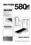
USER'S MANUAL
Model No. 831.290823
Serial No.
Wdte the serialnumberin the space
abovefor futurereference.
Serial Number Decal (under console)
ECrU
[elln
F-----X I=" R C
I PM
I1_,|
n
I _ I_
ENT
|e|
_1
HELPLINE!
1-800-736-6879
andlns_uc-
SEARS, ROEBUCK AND CO., HOFFMAN ESTATES, IL 60179
TABLE OF CONTENTS
IMPORTANT PRECAUTIONS
......................................................
.2
ASSEMBLY .....
, .............................
"" ."
HOW TO USE THE AIR WALKER ... .........................
MAINTENANCE AND TROUBLE-SHOOTING
...................
CONDmONING GUIDELINES ................................
PART LIST .......................................................................
...
.
EXPLODED DRAWING ................................
, ................................
ORDERING REPLACEMENT PARTS ................................................
FULL 90 DAY WARRANTY
....,.....,.
..................................
..
....
.
. .
front of
. .........
4
7
8
9
10
11
Back Cover
Back Cover
this manual,
12, If you feel fain_ dizzy, or short of b_ath While:
8.
• "
Keep hands and feet away from moving parts,
: WA_i_
i _0_
_ln.lng
_ sgr any exerc se program, consult your physician, This is es_ially
!m_r_f0r,_s
_er_,age_of_35
__tn_btli_n,_ing,_,_E_p_S_U_s
•
•
o_
_:_.
_,
.,_
_ .....
_feel faint
dren away.
_....
or _qs
with pre-ex!sting heal_ pr0blems_Read _1_!_ _, :
no_resDonsib!!itv for Per_s_aLin[_ry or,prope_d_=i_ge_,,_
_
_ ........
_:_
.........
......
2
_ _ ......
....
_
_,_ ...........
_
_
_
_
:_
BEFORE YOU BEGIN
Thank you for selecting the Innovative PROFORM"
AIR WALKER. The AIR WALKER blends advanced
engineadng with contemporary styling to provide you
with a no-impact, total body workout in the convenience and privacy of your own home.
Central Time (excluding holida_'o_e_
us:aesist
you, please note the product n_l
number and serial
number before calling. The moddl_umbe_.is
831.290823. The serial number can be found on a
decal attached to the AIR WALKER (see the front
cover of this manual for the location of the decal).
For your benefit, read this manual carefully before
using the AIR WALKER. If you have additional questions, please call our toll-free HELPUNE at 1-800-7366879, Monday through Saturday, 7 a.m. until 7 p.m.
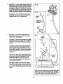
Before reading further, please review the drawing
below and familiarize yourseff with the parts that are
labeled.
Handles
•Monitor
Resistance
Legs
LEFT SIDE
RIGHT SIDE
.. "
Wheels
3
Base
ASSEMBLY
Before you begin assembly, carefully read the
following Information and InstrucUons:
• Read through each assembly step before you
begin.
• Place all pads of the AIR WALKER in a cleared
area and remove the packing materials.
IMPORTANT: DO NOT REMOVE THE RUBBER
BANDS FROM THE HUB COVERS (see
assembly step 5). Do not dispose of any
packing matedals until assembly is completed.
• Make sure that all parts are odented as shown in
the drawings. "lighten all pads as you assemble
them, unless Instructed to do otherwise.
Assembly requires the following tools:
/
• the Included allen wrench
_
-=:J
• Use the drawings below to identify the small
hardware used in assembly.
• your own phillips screwdriver
(__
@©
3/8" x 1/2" Screw (24)-8
3/8" Curved Washer (27)-4
#8 x 1/2" Screw (31)-8
Before you begin, read the Information at the
top of this page.
1,
Fig. 1
RIGHT"
Sticker
Sticker
See figure 1. Rnd the Left Upright (3). Note:
There is a "TOP LEFT" sticker on the upper
end of the Left UpdghL
See figure 1. Slide the Left Updght (3) onto the
Base (1). Thread two 3/8" x 1/2" Screws (24) into
the Left Upright. Do not tighten the Screws yet.
24
See figure 1. Attach the Right Updght (4) in the
same manner.
,
See figure 2. Hold the Top Frame (2) level, and
insert it into the Left and Right Updghts (3 and 4).
Note: It may be helpful to rock the Top Frame
from side to side slightly as you insert IL
Make sure that the indicated rubber bands are
not pinched between the Top Frame and the
Uprights. Attach the Top Frame with four 3/8" x
1/2" Screws (24).
Fig, 2
2
Rubber
Band
See figures 1 and 2. "Rghtenthe eight 3/'8" x 1/2"
Screws (24).
24
4
Rubber
Band
24
3.
See figure 3b. Find the Right Leg (7). Note: The
Right Leg Is marked with a "RIGHT" s{icker.
Set a Pedal (28) on the plate at'the lower end of
the Right Leg. Note: Be careful not to attach
the Pedal backwards. Look at the curve of the
Right Leg and the front end of the Pedal to
make sure that the Pedal is turned correctly.
Fig. 3a
Fig. 3b
See figure 3a. Tum the Right Leg (7) and the
Pedal (28) upside-down as shown. Attach the
Pedal with tour #8 x 1/2" Screws (31).
Sticker
R ght
Curves in This
Direction
Front
End.
.
See figure 4, Look into the upper end of the
Right Leg (7) and make sure that the Plastic
Sleeve (41) is fully inserted,
=RIGHT"
Sticker
See figure 4. Find the Right Handle (11). Note:
The Right Handle is marked with a "RIGHT"
sticker. Insert the Right Handle into the Right
Leg (7).
See figure 4. Slide a 3/8" Curved Washer (27)
onto a 2" Upper Screw (25). Note: Use the
actual-size drawing to Identify the 2" Upper
Screw (25). Insert the 2" Upper Screw into the
upper hole in the Right Leg (7) and the Right
Handle (11).
•", 41
:II
See figure 4. Slide a 3/8" Curved Washer (27)
onto a 2 114"Lower Screw (26). Note: Use the
actual-slze drawing to idantify the 2 1/4"
Lower Screw (26). Insert the 2 1/4" Lower
Screw into the lower hole in the Right Leg (7)
and the Right Handle (11).
//
/
,'
Sticker
' '"
See figure 4. Make sure that the 2" Upper
Screw (25) is in the upper hole, and that the
2 114" Lower Screw (26) is In the lower hole.
The Screws must be inserted from the side
shown.
_%jI/
I
I
I
I
I
I
/J
//
I
I
I
I
I
I
I
I
IJ
_
I
(I
II 2114"
Lower
Screw
(26)
IIIIII
',_!
." ,! i
I
/
!
I
I
/
I
!
I
II
I
112
Note: This step requires one 2" Upper Screw (25)
and one 2 1/4" Lower Screw (26). The 2" Upper
Screw (25) must be in the uppe[ hole; the 2 !/4"
Lower Screw (26) must be |n the 10wet ii_16.
5
.
See figure 5a. Before you begin this step,
make sure that the Right Hub Cover (19) is
attached to the Top Frame (2) with e rubber
band as shown. If the Right Hub Cover has
come off during shipping, see figure 5b.
Slide the Right Hub Cover onto the Right
Pivot Bracket (20).
See figure 5a. Red the two holes inside the slot
of the Right Hub Cover (19). Make sure that the
rubber band Is not covering the holes, and that
the holes are aligned.
See figure 5a. Hold the Right Leg (7) against
the Right Hub Cover (19). Thread the 2" Upper
Screw (25) two complete fume into the upper
hole inside the Right Hub Cover. Thread the
2 1/4" Lower Screw (26) two complete turns
into the lower hole. Break and remove the rubbar band.
See figure 5a. Fully tighten the 2" Upper Screw
(25). After the 2" Upper Screw Is tightened, fully
.tighten the 2 1/4" Lower Screw (25).
Repeat assembly steps 3; 4, and 5 to attach
the Left Leg and the Left Handle (not shown) to
the left side of the AIR WALKER.
.
See figure 6a. Insert two "AA"batteries (not included) intothe Monitor (39). Alkaline batteries are
.recommended. Make sure that the negative (-)
ends of the battedee are touching the springs,
and that the positive (+) ends of the batteries
are pushed against the metal contacts.
Fig. 6a
4O
See figure 6a. Plug the Reed Switch Wire (44)
into the Monitor (39). Insert any excess wire into
the Console (40).
See figure 6b. Snap the Monitor (39) into the
Console (40). Be careful not to pinch the wire
between the Monitor and the Console.
Before you use the AIR WALKER, use the included alien wrench to firmly re-tighten all of the screws used in
assembly.Remove the orange and green identificationstickers from the AIR WALKER. Note: During the first
few minutes that the AIR WALKER is used, s squeaking noise may be heard. This is normal during the
break-in period.
i
HOW TO USE THE AIR'WALKER
ELECTRONIC MONITOR MODES
uAu I iuq:_wnen ,you ore getting onto ana on
the AIR WALKER, always tighten the realstance knobs, hold the handles firmly, end be
sure that your body weight Is centered directly over the pedals.
The simple-to-oporate electronic monitor offers
five different modes to provide Instant exercise
feedback. The five modes are described below:
Reps/min--Displays the number of repetitions you
are performing per minute.
EXERCISING ON THE AIR WALKER
Reps--Displays the total number of repetitions you
have completed, up to "999? The display will then
reset to _' and continue counting.
The proper form for exercising on the AIR WALKER
is similar to walking--move one leg forward as you
move the other leg back. Never attempt to move
both legs In the same direction--you could be
injured, or the AIR WALKER could be damaged.
Calories--Displays the approximate number of
Calories you have burned. Note: If the resistance is
near the highest or lowest setting, the actual number
of Calories you have bumed will be slightly higher or
lower than the number displayed.
For a full body workout, hold the bandies as you walk,
moving your arms and legs in motion with the handles
and pedals. To vary the effect on your muscles,
change your stance on the AIR WALKER. For example, you can change the position of your hands on the
handles, or you can bend your legs slightly instead of
keeping them straight.
Scan All--Displays the reps/min, reps, calories, and
time modes, for approximately 5 seconds each,
in a repeating cycle.
Time-Displays the length of time you have exercised. Note: If you stop exercising for ten seconds or
longer, the time mode will pause until you resume.
For a lower body workout, rest your hands on the
edge of the console for balance as you walk on the
pedals. Note: Do not lean on the console. It Is not
designed to support your body weighL
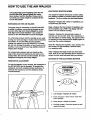
DIAGRAM OF THE ELECTRONIC MONITOR
RESISTANCE ADJUSTMENT
To vary the intensity of your workout, the resistance of
the AIR WALKER can be changed. To increase the
resistance, turn both resistance knobs clockwise. To
decrease the resistance, turn the resistance knobs
counte_ockwise.
1. LCD display-Displays
all modes.
2. Mode ind=cators--Show which mode has
been selected.
3. Mode button_elects
all modes.
4. On/Clear button--Turns the power on and
resets all modes.
7
OPERATING THE ELECTRONIC MONITOR
Repshttln, reps, calories, or time mode--These
modes can be individually selected by repeatedly
pressing the mode button. The mode indicators
will show which mode has been selected. (Make
sure that the scan all mode is not selected.) The
modes will be selected in the following order:.
reps/min, reps, calories, scan all, time.
1. To turn on the power, press the on/dear button or
simply begin exercising on the AIR WALKER. The
entire display will appear for two seconds. The
electronic monitor will then be ready for operation.
2. Select one of the five modes:
.
Scan all mode--When the power is tumed on, the
scan all mode will be selected automatically. The
scan all mode can also be selected by repeatedly
pressingthe mode button. One mode indicator will
show that the scan all mode has been selected,
and a second mode Indicator will show which
The monitor has an auto-off feature to turn off
the power, If the pedals are not moved and the
monitor buttons are not pressed for four minutes,
the power will tum off automatically in order to
conserve the batteries.
To reset the LCD display, press-the on/dear button.
mode is currently displayed.
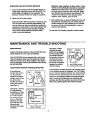
MAINTENANCE AND TROUBLE-SHOOTING
MAINTENANCE
See figure 3. Make
sure that the reed
Inspect and tighten all pods of the AIR WALKER regularly. Replace any wom parts immediately.
switchwireisplugged
intothe monitor;,ineed
any excess wire into
the console. Srap the
monitorinto the console. Make sure that
the wire is not pinched
between the monitor
and the console.
The AIR WALKER can be deaned with a soft, damp
doth. Keep liquids away from the electronic monitor.
Keep the monitor out of direct sunlight or the display
may be damaged. Remove the batteries when storing
the AIR WALKER:
Fig. 3
MonitorI
Reed Switch Wire
ELECTRONIC MONITOR TROUBLE-SHOOTING
If the electronic
monitor will not turn
on, the batteries
should be checked.
Fig. 1
If the electronic monitor still does not function properly, the batteries should be replaced. Two "AA" batteries are required; alkaline batteries are recommended.
Remove the two old batteries from the monitor, and
insed two new bettedss. Make sure that the negative (-) ends of the batteries are touching the
springs, and that the positive (+) ends of the batteries are pushed egalnst the metal contacts.
Console
Using a coin, pry up
the front of the
monitor and remove
R from the console
(see figure 1).
See figure 2. If there
is a gap between
the positive (+) ends
of the battedss and
the metal contacts,
the monitor will not
turn on. Push the
batteries to make
•sure that the positive ends are
touching the metal
contacts.
Fig. 2 _ ,Metal Contact
_"
>Batteries
I
Back of Monitor
3
CONDITIONING GUIDEVINES
The following guidelines will help you to plan your
exercise program. Remember that proper nutrition and
adequate rest are essential for successful results.
WARNING:: Before beginning this i_#ia' exercise
program, consult your ph_s|¢ian. This Is'especlally important for Individuals ove_,,th(eage of 35
or Individuals with pre-exL,_t!ng hea_:prOblems. _'_
WHY EXERCISE?
Exercise has proven essential for good health and
general well-being. Regular participation in a wellrounded exercise program helps to develop a stronger
and more efficient heart, improved respiratory function,
increased stamina and endurance, better weight management and body fat control, increased ability to deal
with stress, and greater self-esteem and confidence.
EXERCISE INTENSITY
To maximize the benefits of exercising, it is important
to exercise with the proper intensity. The proper intensky level can be found by using your heart rate as a
guide. For effective aerobic exercise, your heart rate
should be maintained at a level between 70% and
85% of your maximum heart rate as you exercise.
This is known as your training zone. You can find your
training zone in the table below. Training zones are
listed according to age and physical condition.
Dudng the first few'montn.s or'your e_ereme program,
keep your heart rate near the Io_end of-youl"training
zone as you exercise. After a re,tqmonth_..._f regular
exercise, your heart rate can be increased gradually
until it is near the middle of your training zone as you
exercise.
To measure your heart rate, stop exercising and place
two fingers on your wrist. Take a six-second heartbeat
count, and multiply the result by ten to find your heart
rate. (A six-second count is used because your heart
rate drops quickly
when you stop
exercising.) If your
heart rate is too
high, decrease
the intensity of
your exercise. If
your heart rate is
too low, increase
the intensity of
your exercise.
WORKOUT GUIDEUNES
A well-rounded workout includes the following three
phases:
A warm-up phase, lasting 5 to 10 minutes. Begin with
slow, controlled stretches, and progress to more rhythmic stretches. This will increase the body temperature,
heart rate, and circulation in preparation for strenuous
exercise.
A cardiovascular phase, including 20 to 30 minutes
of exercising with your heart rate in your training zone.
TRAINING ZONE (BEATS/MIN.)
AGE
UNCONDmONED
CONDITIONED
20
138-167
133-162
25
136-166
132-160
30
135-164
130-158
35
134-162
129-158
40
132-161
127-155
45
131-159
125-153
50
129-156
124-150
55
127-155
60
126-153
121-147
65
125-151
119-145 "
70
123--150
118-144
75
122-147
117-142
80
120-146
115-140
85
118-144
114-139
A cool-down phase, consisting of 5 to 10 minutes of
stretching. Thorough stretching offsets muscle contractions and other problem_ caused when you stop
exercising suddenly. Stretching for increased flexibility
is often,most effective dudn_]this phase. This phase
should leave you relaxed and comfortably tired.
To maintain or improve your condition, complete three
workouts each week, with at least one day of rest
between workouts. After a few months of regular exercise, you may complete up to five workouts each
week, if desired. Find the best time of day for your
workouts, and then stick with it.
J22-149
Remember, the key to success is to make exercise a
regular and enjoyable part of your everyday life.
9
I ART LIST---Model No. 831.290823
Key
No, Qty.
1
2
3
•4
5
6
7
8
9
10
11
12
13
14
15
16
17
18
19
20
21
22
23
24
25
26
27
28
29
30
31
32
1
1
1
1
1
1
1
1
1
1
1
8
2
2
2
4
2
2
1
1
2
1
1
8
2
2
4
2
2"
2
8
1
Part
No.
127518
129957
127536
127784
129960
129962
129963
129944
129945
129995
129996
119425
129998
129570
129139
129144
129143
130009
128714
130350
130001
128713
130349
130007
013544
124123
127890
127759
013399
052014
129475
127896
Key
No. Qty.
Description
Base
Top Frame w/Axle Caps
Left Updght
RightUpdght
Rocker Arm wlAxle Caps
Left Leg
Right Leg
Left UnkArm w/Axle Caps
Right Unk Arm w/Axle Caps
Left Handle w/Foam
Right Handle w/Foam
3/8" Nylon Jam Nut
Resistance Housing
Resistance Sleeve
Friction Cone
1/2" Thrust Washer
1/2" Thrust Bearing
1/2" Plastic Washer
Right Hub Cover
Right Pivot Bracket w/Axle Caps
Pivot Sleeve w/Axle Caps
Left Hub Cover
Left Pivot Bracket w/Axle Caps
3/8" x 1/2_ Screw
2" Upper Screw
2 1/4" Lower Screw
3/8" Cuwed Washer
Pedal
3/8" x 1 3/4" Bolt
Wheel
#8 x 1/2" Screw
1/2" x 2" Bolt
33
34
35
36
37
38
39
40
41
42
43
44
45
45
47
48
49
50
51
52
53
54*
55
68
57
53
#
#
2
1
2
6
4
2
1
1
2
2
1
1
2
2
6
1
2
2
1
1
6
1
2
2
2
2
1
1
R0496A
Part
No.
Description
110576
Pivot Bushing
012081
1/2" Nylon Jam Nut
129110
1" Plastic Washer
123116
1 1/2"x3"Endcap
126650
Rubber Foot
129168
#10 x 1/2" Metal Screw
127762
Electronic Monitor
127761
Console
127765
Plastic Sleeve
127945
Foam Grip
110277
#8 x 3/8" Screw
128775
Reed Switch wANim
1L_Jt45 Resistance Cover
129146
Resistance Knob
129187
3/8" x 2" Cordage Bolt
100498
Magnet
129;tOt
#3 x 1/4" Screw
110468
3/8" Lock Washe_
129064
Retainer
1_Z9065 Magnetic Concentrator
108404
#8 x 3/4" Metal Screw
129063
Console Assembly
130008
Retaining Ring
129945
Unk Arm Bushing wlAxle Caps
101768
Dome Cap
104365
Snap Ring
130353
User's Manual
128457
Allen Wrench
* Includes all pads shown in the box
# These parts are not illustrated
Note: Specifications are subject to change without notice. See the back cover of this manual for information
about ordering replacement parts.
10
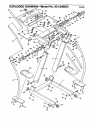
EXPLODED DRAWING-/-._Model No. 831.290823
Ro4_,_
46
12
18
16
15
12
\
5O
24
56
13
47
23
36
12
14
16
18
24
28
/
/
24
/
31
36
29
12
31
11
12
3O
31
S£ARS
The model number and serial number of your PROFORM =AIR
WALKER are listed on a decal attached to the frame. See the front
cover of this manual to find the location of the decal.
Model No. 831.290823
If you find that:
All replacement pads are available for immediate pumhase or
special order when you visit your nearest SEARS Service Center.
To request service or to order parts by telephone, call the toll-free
numbers listed at the left.
• you need help assembling or
operating the PROFORI_PAIR
WALKER
When requesting help or sea,ice, or ordedng pads, please be prepared to provide the following information:
• a part is missing
• The NAME OF THE PRODUCT (PROFORIVP AIR WALKER)
• or you need to schedule repair
service
• The MODEL NUMBER OF THE PRODUCT (831.290823)
call our toll-free HELPMNE
• The PART NUMBER OF THE PART (see page 10 of this manual)
QUESTIONS?
1-800-736-6879
• The DESCRIPTION
OFTHE PART (see page 10 of this manual)
Monday-Saturday, 7 arn-7 pm
Central Time (excluding holidays)
REPLACEMENT
PARTS
If parts become wom and need to
he replaced, call the following
toll-free number
1-800-FON-PART
(1-800-366-7278)
I
FULL 90 DAY WARRANTY
I
For 90 days from the date of purchase, if failure occurs due to defect in material or workmanship in this
AIR WALKER EXERCISER, contact the nearest SEARS Service Center throughout theUnited States
and SEARS will repair or replace the AIR WALKER EXERCISER, free of charge.
This warranty does not apply when the AIR WALKER EXERCISER is used commercially or for rental pup
poses.
This warranty gives you specific legal rights, and you may also have other rights which vary from state
to state.
SEARS, ROEBUCK AND CO., DEPT. 817WA, HOFFMAN ESTATES, iL 60179
Part No. 130353 F(X)672-C R0496A
Printed in USA© 1996 Sears, Roebuck and Co.