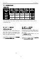
1
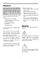
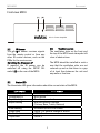
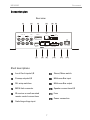
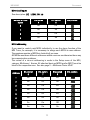
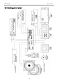
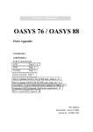
o M219 Standard.E20.E40.E80 Side room amplifier E 2.00 M219 MK2 Re:connect Contents M219 Mk2 Additional room amplifier M219 Mk2 Re:sound I invisible Installation and operation Safety measures Warranty 2 2 3 4-5 5 Front view Connection plan Detailed description [1] Local IN 1 2 3 [2] PRE OUT [3] DIL Setup switches (1) IR receiver (2) Pre Out (3) Input IN (4-5) Local inputs (6-7-8) Addressing 6 7 8 8 8 9 9 10 11-12 13 13 [4] [5] [6] M219 Link IR Link Input IN 14 14 15 [7] [8] [9] [10] [11] [12] Channel Select IN Revox MR Bus OUT Revox MR Bus R-L Speakers Fuse AC Power 15-16 16 16 17 17 17 M219 cabling plan diagram Multiroom Cabling 18 19 Personal M219 settings Technical data Guarantee Delivered items M219 variants: Standard, E20, E40, E80 19 20 21 21 21 1 M219 MK2 Re:connect General Multiroom Planer V2.00 The M219 is a digital Side Room Amplifier from the M Series in the Revox Multiroom programme. It is used for the reproduction of music in the additional rooms in a Multiroom system and can also supply the listener with current information through an additional display. The M219 receives the signals from a selected source (Multimedia, Tuner, Server ...) in the main room through a multiroom bus cable. Volume, balance, bass and treble settings can be made in individually in each room. Also, up to 3 local sources can be connected and listened to in each additional room. If you want “concealed” operation, various wallmounted controllers or IR receivers can be connected. The new Multiroom Planner doesn't just calculate the correct address assignment for the M219 Side room amplifiers and M217 Wall-mounted displays, it also calculates the slot addresses for the M200 series Re:control products in the side room. Take advantage of the possibility to be able to determine in advance, all M200, M217 and M219 addresses simply and quickly and at the same time save the information as system documentation. You can download the new Multiroom Planner V2.00 free-of-charge from the download area of the Revox Homepage, under www.revox.com. M219 Re:sound I - Invisible As well as the standard model of the M219 MK2 (Part no.: 1.551.060.01) with linear amplifier characteristic curve, there are two further versions with adaptive characteristic curve for the Re:sound I speaker with 40 and 80 watts. These Invisible speakers work out of sight under plaster or a coat of paint and therefore, need a general modification. The M219 versions E20 (art. no.: 1.551.060.05) E40 (art. no.: 1.551.060.02) E80 (art. no.: 1.551.060.03) are operated like the normal version of the M219. The only differentiating point is the additional card for the adaptive amplifier characteristic curve that is installed in the device. Stacking several M219s If you want to stack several M219s on top of each other, we recommend that you use the corresponding installation kit, with the Part no. 1.551.313.00. M219 Room-Amplifier M219 Room-Amplifier M219 Room-Amplifier 2 M219 MK2 Re:connect Installation Please follow the instructions in the Operating manual supplied. Unplug the unit from the mains during storms. Voltage peaks through the mains power supply caused by lightning strikes can damage the unit. Do not position the device close to strong heat sources or in direct sunlight. There must be easy access to the power plug so that the unit can be unplugged at all times. If installing in a cabinet or closed shelves, allow at least 5 cm (2 in.) of free space around the device, so that the air can circulate freely and that there is no build up of heat. Lay the power cable such that it cannot be damaged. The power cable should not have kinks or by laid over sharp edges. It should not be walked on or be exposed to any chemicals. The last point is valid for the whole unit. A power cable with damaged insulation can lead to electric shocks and represents a fire hazard. Ensure that the ventilation is not impeded by covering the ventilation openings with items such as newspapers, table-cloth, curtains, etc. This device conforms to protection class 2. This means that the unit is only connected to the mains power socket through two contacts (phase and neutral) and has no ground. For this reason, the unit must pass a strict insulation test. This guarantees that even if the neutral line is broken, no accessible part of the unit is under voltage. The M219 is equipped with this protection class in order to effectively eliminate sound-damaging ground-loops. Never pull on the cable when plugging the unit in or out. Always hold the plug. Fluids, flammables or other foreign objects should not find their way into any of the unit’s openings as this can result in breakdowns, fire or an electric shock. Furthermore you may not place objects filled with liquids, such as vases, or naked flame sources, such as lighted candles, on the M219. The power plug should removed from the socket during longer periods of non-use, for instance during an absence. Use the apparatus only in moderate climates (not in tropical climates). 3 M219 MK2 Re:connect Safety measures Protect your device from: - Damp, dripping water and splash water, steam. - Knocks and mechanical loads. - Magnetic and electrical fields - Cold, heat, direct rays of the sun and severe changes of temperature - Dust - Access to the inside of the device - Do not stand any articles with open flames, e.g. lit candles on the device Read and take note of the following safety advice for your own safety and to avoid unnecessary damage to your equipment. Please keep this safety advice in a safe place for future reference. Avoid locating the unit in a position which: - is exposed to direct sunlight - is directly next to a source of heat - has poor ventilation - has a dusty atmosphere - is unstable - has high humidity Safety symbols Take note of the label on the back of the unit. The guarantee covers intended usage of the device. High build-ups of dust and humidity cause creepage current in the device that can cause a risk of shocks when touching the unit or lead to a fire. If you have moved the unit from a cold to a warm environment, leave it switched off for about two hours because of a possible build up of condensation dampness. This symbol warns of “dangerous voltages” within the unit. In the case of contact with the corresponding components, the level of voltage can cause an electric shock. You should always switch your M219 off before connecting or disconnecting other devices or speakers. This symbol indicates important advice for operation and maintenance in this documentation. 4 M219 MK2 Re:connect Regulations pertaining to the unit Caution In order to avoid the risk of an electric shock, do not remove any covers. Maintenance and repairs should only be carried out by qualified Revox experts. In EU and EEC countries, Revox offers a guarantee on units bought in the EU, over and above the statutory rights of guarantee claims against the seller. The guarantee covers material and labour during the period of the guarantee, which is defined by the Revox Sales Partners in the individual countries that make up the EU. Volume Loud music can cause hearing damage. Avoid extremes of volume, particularly over longer periods of time and if you are wearing headphones. In all countries, the guarantee services offered by the Revox Sales Agent are over and above the statutory regulations. They are only valid in the country of purchase. Proof of purchase from an authorised Revox Partner must be produced to make a claim on the guarantee. Supervision Do not allow children to handle the equipment without supervision. Do not allow children in close proximity to the equipment. Do not operate the M219 without supervision. Unplug the equipment if you are going to be absent for a longer period of time. The guarantee is made null and void in the case of incorrect intervention measures or non-professionally executed repairs. Cleaning The device should be cleaned using just a damp, soft and clean cloth without any abrasive cleaning agents. Fuse The M219 is equipped with a primary power fuse. The power fuse should only be checked or replaced after the power cable has been unplugged. Check the fuse specification on the unit label before inserting the new fuse. If the new fuse also blows after switching the device back on, there is probably an underlying error that must be checked out by a specialist. In this case, please contact your nearest Revox Service Point. 5 M219 MK2 Re:connect Front view M219 [A] [B] [C] M219 Room-Amplifier [C] Ventilation slots The ventilation slots on the front and the top of the M219 must always be left clear of obstructions. [A] IR Sensor The InfraRed sensor receives signals from the remote control or from any other IR control devices, such as the PDAs for the music server. Switching the IR sensor off If required, the IR sensor can be switched off using the SETUP DIL switch [3] on the rear of the M219. [B] The M219 should be installed in such a way that the ventilation slots are not covered up and so that there is a gap of at least 5cm between the unit and any walls or furniture. Status LED The blue status LED gives information about the current state of the M219. LED display Permanently dark Permanently lit Rapid flashing Rapid flashing Slow flashing Single flash Double flash Triple flash M219 Status M219 standby mode M219 active Breakdown, overload Min/max position reached (Volume, Bass, Treble, Balance) IR receive (RC5 or RC6 Codes) LOCAL 1 or general change of source LOCAL 2 LOCAL 3 6 M219 MK2 Re:connect Connection plan Rear view [1] [2] [3] LOCAL IN PRE OUT SETUP [4] [5] [6] + IN - + - M219 LINK 1 2 3 L OUT 1 2 3 4 5 6 7 8 R 1 2 3 4 CHANNEL IN SELECT [7] [8] + R- L + SPEAKERS FUSE AC - POWER MR-BUS [9] [10] [11] [12] OUT Short descriptions [1] Local Cinch inputs L/R [7] Stereo/ Mono switch [2] Preamp outputs L/R [8] Multiroom Bus input [3] DIL setup switches [9] Multiroom Bus output [4] M219-Link connector [10] Speaker connections L/R [5] IR receiver or wall-mounted remote control connections [11] Fuse [6] Switching voltage input [12] Power connection 7 M219 MK2 Re:connect Detailbeschreibung [1] [2] LOCAL IN 1 2 3 PRE OUT Local Cinch inputs L/R Preamp outputs L/R The M219 has 3 local line inputs for a CD player or TV, for example, which are located directly in the room where the M219 is. The local audio inputs are activated by the Local key on the (wallmounted) remote control. You can scroll through a loop of the local inputs by repeatedly pressing the Local key: Using the M219s preamp outputs, additional output devices can be supplied, or the Revox digital speakers can be operated through the Revox DLC-2. The configuration of this audio output is described in detail on Page 10. (Local 1 (Local 2) [3] (Local 3) DIL Setup switches The number of active inputs that are actually used can be set through Setup DIL switches (4 + 5 ). This saves you unnecessary scrolling through nonactive inputs. If, for example, only inputs 1 and 2 are used, you can set the switches so that you only have to scroll through Inputs 1 & 2. Input 3 is skipped. SETUP The basic settings of the M219 are configured through these DIL setup switches. 1 2 3 4 5 6 7 8 Important Configuration can only be carried out through the setup switches when the M219 is disconnected from the power supply. Otherwise, the new settings are not activated. Special feature With the remote button TV of the remote control the Local input 1 can be explicit selected in order to select a local (TV) device. The function of each individual switch is described on the next page. 8 M219 MK2 Re:connect DIL setup switches NO Function Factory setting 1 M219 IR eye on/off On 2 Pre-Out: Fixed Volume Off 3 LOCAL IN 1 Fixed Volume Off 4 Number of local inputs On 5 Number of local inputs On 6 M219 address Off 7 M219 address Off 8 M219 address Off Please note: The switch is in the ON position when it is down You can enter your own personal DIL switch settings in a table included on the last pages of this manual, providing you with a record for future reference. M219 infrared receiver In some cases, e.g. in buildings with glass internal walls, it can be useful to switch the M219 IR receiver off, in order to avoid operational conflicts with other devices. IR Function DIL switch 1 IR - Off Off IR - On On DIL position 1 1 9 M219 MK2 Re:connect (2) PRE OUT Two operating modes are possible with the M219’s preamp output: Floating Volume (Factory setting from serial # 2000): This is the standard mode setting. In this case, the PRE OUT level changes parallel to the speaker level. This means that as you increase the volume at the speakers, for example, the PRE OUT level is automatically changed at the same time. Application: You should select Floating Volume mode if, for example, and additional output device or an active subwoofer is connected, whose volume should also be controlled by the M219. This means that the M219 speaker output remains active. Fixed Volume: In this mode, the volume control and the M219 output devices are deactivated, i.e. the volume cannot be controlled by any wall-mounted or infrared remote control. The speakers connected to the M219 remain silent. Irrespective of whether it is addressed through the multiroom bus or a local input (Local IN 1 2 3), each source has a standard level, the so-called Line Level. Application: The Fixed Volume mode has been conceived principally for applications where digital Revox speakers are to be connected to the M219 over a DLC2 interface. PRE OUT DIL switch 2 Floating Volume Off Fixed Volume On DIL position 2 2 10 M219 MK2 Re:connect (3) Voltage input IN (from serial # 2000) INFO Using the voltage input IN on the M219, the local audio input LOCAL IN 1 can be activated by the application of 5 – 24 VDC. This means that as soon as the voltage is present at IN, the M219 switches on automatically and selects the input LOCAL IN 1. When the voltage is removed from input IN, the M219 switches off again automatically, as long as no other source apart from LOCAL IN 1 was addressed. With DIL switch (3), you can define whether the volume control is handled by the M219 (Floating Volume) or the connected (TV) device (Fixed Volume). With Fixed Volume, the M219’s volume control is deactivated and the audio signal at LOCAL IN 1 is transmitted with a fixed strength. In this way, volume control is carried out with the TV remote control. The volume control setting set by DIL switch 3 only has an effect on the local audio input LOCAL IN 1. All other sources are unaffected and operate normally. LOCAL IN 1 DIL switch 3 Floating Volume Off Fixed Volume On Application: DIL position 3 3 Many devices output a voltage as soon as they are switched on. If you connect the voltage output of such a device with the IN voltage input on the M219 and the audio output with the local audio input LOCAL IN 1, the M219 will switch on automatically with the other device and transmit the sound. If your device doesn’t have a voltage output, you can supply voltage to the input using a sensor-switch multiple socket outlet (Master/Slave socket outlet) and a normal plug-in power supply (5-24 V= / DC). Please refer to the diagram on Page 12. 11 M219 MK2 Re:connect Cabling: Voltage input IN Audio Local (audio)-source OUT e.g. TV WITHOUT + WITH - M219 LINK LOCAL IN 1 2 3 PRE OUT SETUP + IN - Slave Slave switching-voltage output 5-24V OUT DC 5-24V OUT DC Slave Audio Local (audio)-source OUT e.g. SAT-receiver Master switching-voltage output IN + - ON 1 2 3 4 5 6 7 8 L 115V / T1A L R ON 1 2 3 4 CAUTION RiSK OF ELECTRIC SHOCK DO NOT OPEN CHANNEL SELECT IN OUT MR-BUS + R- FUSE - L + SPEAKERS AC - POWER 230V / T0,5A L Please note: SCART sockets Many devices such as SAT receivers, video recorders or DVD players output a switching voltage through the SCART socket as soon as they are switched on. On a standard SCART socket, PIN 8 outputs the positive voltage (+) and PIN 4 or 14 is the earth (-). The principle of Master/Slave socket outlets With this type of socket outlets, the control device (the TV in the above example) is plugged into the master socket while all other devices are connected through the slave sockets. As long as the master device is not switched on, all slave sockets remain switched off. Once the master device is switched on, all the slave sockets (the plug-in power supply in the above example) are switched on at the same time. In this way, you can “upgrade” any type of device to give it a switching-voltage output. 12 M219 MK2 Re:connect M219 local inputs See description: [1] LOCAL IN 1 2 3 Number of local inputs DIL switch 4 DIL switch 5 0 Off Off 1 Off On 2 On Off 3 On On DIL position 4 5 4 5 4 5 4 5 M219 addressing If you want to control each M219 individually, to use the alarm function of the M51 Timer, for example, it is necessary to assign each M219 its own address. The maximum number of M219s is limited to 8 per zone. All M219s must have different addresses within one zone as otherwise there may be communication problems. The revisal of a correct addressing is made in the Setup menu of the M51, category Multiroom / Version. All attached devices (M219 and/or M217) must be listed in the respective zone. See also page 2 – Multiroom Planer V2.00 Address DIL switch 6 DIL switch 7 DIL switch 8 1 Off Off Off 2 Off Off On 3 Off On Off 4 Off On On 5 On Off Off 6 On Off On 7 On On Off 8 On On On 13 DIL position 6 7 8 6 7 8 6 7 8 6 7 8 6 7 8 6 7 8 6 7 8 6 7 8 M219 MK2 [4] Re:connect [5] IR-LINK Connection for IR receiver or wallmounted remote control M219-Link - M217 Display connection - M200/ M203 TV interface If it is not possible or not required that the M219 is controlled directly with a remote control, a wall-mounted remote controller (e.g. M218) or and external IR eye (MR-204) can be connected to the IR-LINK connector. Connection to the IR receiver or the wall-mounted remote controller is made using a screwable Phoenix plug connector. The external display M217 or a M200- / M203 interface can be connected to the M219-Link connector. Connection is made using a straight through (not crossed), 4-core telephone cable with an RJ11 plug (6P4C-Modular) connected to the M219 LINK socket. 1 only available at side room amplifiers with address X1-X4 Revox recommends the use of a 3core, screened cable² (microphone cable), where the screening is used as an earth. This cable may not be longer than 30 meters. Please refer to the label for the correct cabling: GND A B VCC + Positive feed IN IR Signal - Earth Front view of RJ11 Connector VCC Data GND Tthe maximum number of IR receivers per M219 is 3. IR commands The M219 accepts all RC5 commands and carries out those that are intended for it. All others are transferred on to the Multiroom central unit. ² Comment A 3-core cable with screening is recommended. In this case, no further cable would be necessary if you added an additional display at a later stage. 14 M219 MK2 [6] Re:connect IN Voltage input (from serial # 2000) Using the voltage input IN on the M219, the local audio input LOCAL IN 1 can be activated by the application of 5 – 24 VDC. This means that as soon as the voltage is present at IN, the M219 switches automatically to LOCAL IN 1, irrespective of which source had been selected previously. For further information please refer to DIL switch (3) / Page 11. Please note: The voltage input IN is galvanically isolated from the M219 with a highresistance (10kΩ) optical coupler. This stops any disturbances from either side having any effect. [7] CHANNEL SELECT Stereo/ Mono switch Using the Channel Select switch, you can adjust the operating mode of the two music (stereo) channels, to the requirements of the room where the M219 is installed. Three operating modes are available: 1) Stereo The left music channel is reproduces through the left speaker connector and the right channel through the right connector. 2) Inverse stereo After installation, it can occur that the left and right speaker connections have been inverted or that the sound picture is not correct for the normal listening position. In this case, a quick solution is offered with the Inverse stereo operating mode, which inverse the assignment of the left and right speaker connectors. 3) Mono If only one speaker is connected to the M219, or if the M219 is controlling two speakers, each in a different room, you should select the Mono operating mode. This means that each speaker receives all the music information. The configuration of the Channel Select switches is described on the next page. 15 M219 MK2 [7] Re:connect CHANNEL SELECT Configuration Operating mode DIL- 1 Switch DIL- 2 Switch DIL- 3 Switch Left channel DIL- 4 Switch DIL Position Right channel Stereo On Off Off On Inverse Stereo Off On On Off Mono On On On On 1 2 3 4 1 2 3 4 1 2 3 4 You can change the switch settings during operation if the volume level is turned down low. [8] [9] OUT Revox MR-BUS Multiroom Bus output IN Revox MR-BUS Multiroom Bus input Connection for a further M219, which is connected with a Revox Multiroom Bus cable. A maximum of 8 M219s can be connected in this way. Connection of the Revox Multiroom Bus cable, which is connected to the Multiroom central unit (e.g. MR module MK3 of the M51, M10, M100). Connection is made using a screened and uncrossed RJ45 cable. Connection is made using a screened and uncrossed RJ45 cable. 16 M219 MK2 Re:connect FUSE [10] R – L SPEAKERS Speaker connection [11] Fuse Always use a cable of a sufficient diameter for connecting your speakers to the M219. Always power the unit down before replacing the fuse. When replacing the fuse, always one of the same type as shown on the M219 rating label. Revox recommends: up to 15m / 50ft: 1.5 mm2 / AWG15 up to 30m / 100ft: 2.5 mm2 / AWG13 over 30m / 100ft: 4.0 mm2 / AWG11 100-120 V AC: T 1,0A L 250V 200-240 V AC: T 500mA L 250V We recommend not to use cables longer than 50m, due to the unavoidable loss of HiFi reproduction. Other fuse types with different power, voltage or operational characteristics can endanger your life and damage the unit. Each individual speaker must have an impedance of 4 or higher. You must ensure that all cable strands are within the screwable Phoenix connector and that none of them come into contact with any adjacent connectors or the M219 housing. The fuse holder can be removed by pushing it in slightly and then turning it in the direction of the arrow. [12] You will only be assured of a perfect stage-quality reproduction if you ensure correct polarity when connecting. A wrong polarity will not cause any damage to the speaker or to the M219, but it can result in imprecise and diffused reproduction that is weak in the base ranges. AC-POWER Power connection Only use the Revox power cable supplied. You must also ensure that the power supply used delivers the voltage as shown on the M219 rating label (120V/ 240V). If required, the M219 can be modified to work with other voltages. This modification should only be carried out by an authorised specialist. 17 M219 MK2 Re:connect M219 Cabling plan diagram 18 M219 MK2 Re:connect Multiroomverkabelung Multiroom cabling uses a CAT 7 cable, in accordance with the international network standard EIA/TIA-568-B. The CAT 7 cable is characterised by 4 twisted pairs, where each pair has its own screening. There is a complete screening around all four pairs. This EIA/TIA-568-B standard provides for the following assignment: Clamp 1 2 3 4 5 6 7 8 Colour code wh/or or wh/gn bl wh/bl gn wh/bn bn MR-signal RX TX L+ R+ R- L- GND MR GND Personal M219 Settings (DIL switches) Room e.g. Bedroom 1 X 2 3 DIL setup switches 4 5 6 7 8 Off Off Off Off Off Off Off Off On On On On On On On On Off Off Off Off Off Off Off Off On On On On On On On On Off Off Off Off Off Off Off Off On On On On On On On On Off Off Off Off Off Off Off Off On On On On On On On On Off Off Off Off Off Off Off Off On On On On On On On On Off Off Off Off Off Off Off Off On On On On On On On On Off Off Off Off Off Off Off Off On On On On On On On On Off Off Off Off Off Off Off Off On On On On On On On On Off Off Off Off Off On X On X 19 On X Off On X Off On X On X On X Off On M219 MK2 Re:connect Technical data AMPLIFIER PART: Music power: 2 x 50 Watt at 4 Ohm / 1% THD 2 x 25 Watt at 4 Ohm / RMS Frequency range: 10 Hz - 25 kHz / -3 dB Damping factor: > 200 at 8 Ohm / 1 kHz Harmonic distortion: 0.03 % at 10 Watt GENERAL M219 DATA: Power voltage: 200-240 V AC 100-120 V AC Power fuse rating: T 500mA L 250V T 1,0A L 250V Power consumption: Max. Operation: Standby: 115 Watt 7 Watt* 2 Watt * at room volume without additional devices Operating conditions: (Humidity rating acc. DIN 40040), “+10°... +40°C” / “+50°…+104°F” Dimensions: Width: 225 mm (8.86 in) Height: 60 mm (2.36 in) Depth: 160 mm (6.30 in) Weight: 2.4 kg Errors and technical modifications excepted. 20 (5.3 lb) M219 MK2 Re:connect Guarantee Delivered items The guarantee period is 24 months from the date of purchase. Your dealer should be your first contact if you need service. If he can't give you the help you need, send the M219 carriage free and without any accessories to your national Sales Office. M219 Multiroom amplifier Power cable Installation instructions Side room amplifier versions: M219 Standard (Part no.: 1.551.060.01) With linear characteristic curve for all Revox speakers, except the invisible. Please supply a complete description of the problem and a full return postal address. M219 E20 (Part no.: 1.551.060.05) With adaptive characteristic curve for Re:sound I invisible from the 20 watt performance class. M219 E40 (Part no.: 1.551.060.02) With adaptive characteristic curve for Re:sound I invisible from the 40 watt performance class. M219 E80 (Part no.: 1.551.060.03) With adaptive characteristic curve for Re:sound I invisible from the 80 watt performance class. 21 M219 MK2 Re:connect M219 Side room amplifier - Operating instructions / Part no.: 10.30.3017 22