1
INSTALLATION MANUAL
DIGITAL FULL COLOR
MULTIFUNCTIONAL SYSTEM
MODEL
MX-4140N/5140N
MX-4141N/5141N
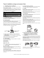
Parts marked with " " are important for maintaining the safety of the set. Be sure to replace these parts with
specified ones for maintaining the safety and performance of the set.
SHARP CORPORATION
This document has been published to be used
for after sales service only.
The contents are subject to change without notice.
MX-5141N
Transit, Installation (using) environment,6HUYLFH0DQXDO
Note
1. Installing (use) conditions
(3)
Before installing the machine, check that the following installing
(use) conditions are satisfied.
If the installing (use) conditions are not satisfied, the machine may
not display full performances, resulting in troubles. It may also
cause safety problems. Therefore, be sure to arrange the installing
(use) conditions before setting up the machine.
No.
1
2
3
4
5
Content
Transportation space
Installing space
Power source (Capacity, fluctuation, safety)
Floor strength
Direct rays of the sun, dust, temperature, humidity, gases,
chemicals
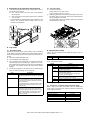
Power frequency, waveform
The frequency must be within the range of the specified frequency
2%. If power waveform is deformed, a trouble may occur.
(4)
Safety
Be sure to properly ground the machine.
Grounding (earth connection) must be performed before inserting
the power plug into the power outlet.
When disconnecting the earth connection, be sure to disconnect
the power plug from the power outlet in advance.
(5)
Power plug
Check the shape of the power plug of the machine, and insert it into
a power outlet of the acceptable shape.
Power plug stated in power capacity.
D. Floor strength and level
A. Transportation space
For installation of a large size machine, be sure to check that the
door size is wide enough before bringing in.
This machine is considerably heavy and becomes heavier with an
option installed.
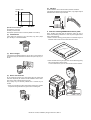
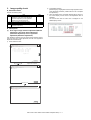
B. Installing space
The floor must be strong enough to safely support the weight of the
machine as well as any installed options.
The following space must be provided around the machine in order
to assure machine performances and proper operations.
If the unit is not horizontally installed, the toner density control is not
performed normally, degrading the copy quality.
If any option is installed, provide the additional space for installing
it.
Adequate space must be provide behind the machine for proper
ventilation heat and dust. If not, the machine cannot exhibit functions against heat and dust, causing some troubles.
If not, color shift or image distortion may occur.
To assure proper Image quality, make sure the machine is setting
level.
11-13/16"
(30cm)
11-13/16"
(30cm)
17-23/32"
(45cm)
C. Power source (Capacity, voltage, frequency,
safety, plug)
If the power specifications are not satisfied, the machine cannot
exhibit full performances and may cause safety trouble.
E. Direct rays of the sun, dust, temperature,
humidity, gasses, chemicals, vibration
(1)
Temperature and humidity (Environmental
conditions)
(1) Power capacity
This machine is designed to perform properly under the specified
temperature and humidity. If the temperature and humidity exceeds
the specified range, the machine may not operate properly and or
cause equipment failure.
Check that the following power capacity is satisfied. If not, additionally provide a power source.
Especially when the humidity is too high, paper absorbs humidity to
cause a paper jam or dirty copy.
Current capacity
Do not install the machine near a heater, a cooler, or a humidifier.
Strictly observe the following specifications.
Japan: 20A or more
EX100V: 20A or more
EX200V: 10A or more
NOTE: Check the shape of the power plug of the machine, and
insert it into a power outlet of the acceptable shape.
(2) Power voltage
Measure the voltage during copying to check that the voltage is in
the range of the specified voltage 10%.
If the voltage is outside the specified range, please have a certified
electrician upgrade the outlet.
Condensation may form inside the machine causing multiple troubles. Use enough care for ventilation.
(An electrical work is required.)
Use of a step-up transformer is also available. In this case, the
capacity must be great enough for the max. power consumption of
the machine.
MX-5141N Transit, Installation (using) environment, Note – i
(5)
Vibration
Humidity㧔RH㧕
Avoid installation near a machine which produces vibrations.
85%
If vibrations are applied to the copier machine, copy images may be
deflected and a trouble may be caused.
60%
20%
Operational environment
Temperature: 10 to 35C
Humidity: 20 to 85% RH
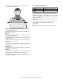
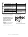
F. Note for handling PWB and electronic parts
Atmospheric pressure: 590 to 1013hPa (altitude: 0 to 2000 m)
(2) Contaminates
If dust enters the machine, it may cause dirty copy and a paper
jam, resulting in a shortened lifetime.
When handling the PWB and the electronic parts, be sure to
observe the following precautions in order to prevent against damage by static electricity.
? When in transit or storing, put the parts in an anti-static bag or an
anti-static case and do not touch them with bare hands.
(3) Direct sunlight
If the machine is installed under the rays of the sun, the exterior of
the machine may be discolored and abnormal copies may be produced.
? When and after removing the parts from an anti-static bag (case),
use an earth band as shown below:
? Put an earth band to your arm, and connect it to the machine.
(4) Gases and chemicals
Do not install the machine at a place where there are gases and
chemicals. Especially be careful to avoid installation near a diazotype copier, which produces ammonium gas.
Copy quality may be adversely affected and a trouble may be
caused.
* There was a trouble in a place where silicon-series gas or volatile
components are generated. Use great care for avoiding this.
MX-5141N Transit, Installation (using) environment, Note - ii
? When repairing or replacing an electronic part, perform the
procedure on an anti-static mat.
2. Transit and delivery
No.
1
2
Content
Implements, facility,
and man power
Delivery
Method
Use a forklift. (If no forklift is available,
manpower of two persons is required.)
Transit must be made in packed condition.
A. Implements, facility, and manpower
It is recommendable to use a forklift for bringing in the machine for
safety.
If no forklift is available, man-power of two persons is required. The
machine is considerably heavy, and requires safety precautions for
delivery and installation.
Transit of the machine must be made in packed condition to the
installing place.
Since the hard disk drive is built in the machine, use care not to
exert vibrations or shocks to the machine when in transit.
B. Delivery
Remove the packing materials prior to installation in the office environment.
G. Note for proper drum, developing, fusing and
transfer unit handling
When handling the OPC drum, developing and transfer units,
observe the following items.
Drum unit
? To prevent damage to the OPC drum, avoid working on the drum
unit in high intensity light areas.
? When the OPC drum is removed from the machine, cover it with
light blocking material. (When using paper, use about 10 sheets
of paper to cover it.)
? Be careful not to attach fingerprints, oil, grease, or other foreign
material on the OPC drum surface.
Transfer unit
? Be careful not to "leave” fingerprints, oil, grease, or other foreign
material on the transfer roller, primary transfer belt and secondary transfer belt.
Developing unit
? Be careful not to "leave” fingerprints, oil, grease, or other foreign
material on the developing unit.
Fusing unit
? Be careful not to "leave” fingerprints, oil, grease, or other foreign
material on the fusing roller and the external heating belt.
? Do not leave the fusing roller in contact state for a long time.
If these items are neglected, a trouble may be generated in the
copy and print image quality.
MX-5141N Transit, Installation (using) environment, Note – iii
MX-5141FN
6HUYLFH0DQXDO
[2] MX-4140N/4141N/5140N/5141N (MAIN
UNIT)
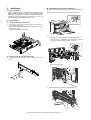
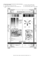
1.
Unpacking
A. Unpacking procedure
1)
Remove the PP band.
2)
Remove the internal packing pads with the machine.
C. Packed items check
B. Removal of the fixing tape and protection
material
1 *1
No.
1
2
3
Name
Developer *1
Operation manual
Operation manual pocket
*1: North America only.
DSPF model
RSPF model
MX-5141FN MX-4140N/4141N/5140N/5141N (MAIN UNIT) 2 – 1
2
3
Quantity
4
1
1
2.
Installation
B. Developing (each color) installation
Note before installation
* When connecting the main unit with the optional STAND/1 X 500
SHEET PAPER DRAWER or STAND/2 X 500 SHEET PAPER
DRAWER, first unpack and install the PAPER DRAWER then
unpack the main unit and securely place the main unit on the
PAPER DRAWER before installing the main unit.
Be careful not to attach fingerprints or oily dirt on the DV roller surface.
1)
Open the front cabinet, and remove the waste toner box.
A. Lock release
1
(1) Tray rotation plate lock release
1)
Pull out the tray. Turn the fixing material and remove it.
Remove the caution label.
Attach the removed fixing material to the position shown in the
figure for future use.
Close the tray which was pulled out.
2
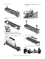
2)
Check that the lock is released as shown in (A).
Loosen the blue screw, and open the drum positioning unit.
* When the lock is not released, use a screwdriver to turn the
screw (B) counterclockwise so that it is fit as (A).
A
B
(2) Scanner (2/3 mirror unit) lock release
1)
Remove the optical unit fixing screw, and remove the note
label.
3)
Open the DV lock lever, and release the fixing screw.
(1position for each color)
1
2
3
1
2
4)
Pinch the knob and remove the development unit.
MX-5141FN MX-4140N/4141N/5140N/5141N (MAIN UNIT) 2 – 2
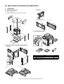
5)
8)
Remove the screws.
Install the DV cover in the arrow direction A.
* When installing the DV cover, be sure to engage the pawl
with the boss.
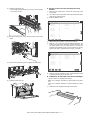
6)
7)
Hold the sections A, and remove the DV cover in the arrow
direction (B).
9)
Secure the DV cover with the two screws.
Supply developer (Packed items) in the developer unit.
* Shake the bag of developer with unopened state. After stirring toner and developer in the bag, supply it to the developing unit.
* When replacing developer, use an extreme care not to drop
developer on the drive section (marked with ( )).
10) Shake the developer unit horizontally a few times.
* When supplying developer, do not tilt the developing unit.
MX-5141FN MX-4140N/4141N/5140N/5141N (MAIN UNIT) 2 – 3
11) Install each developer unit.
* When installing the developer unit, be sure to check that the
DV lock lever is open.
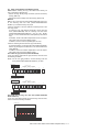
C. Set the control level for the reference toner
density
1)
With the front cabinet open, connect the power plug to the
power outlet.
2)
Turn ON the main power switch of the machine and the power
switch on the operation panel.
3)
Enter the SIM25-2 mode.
ǂǂǂ6,08/$7,21ǂǂ12
7(67
&/26(
$8720$7,&'(9(/23(5$'-8670(17
$7'(9($'-B/B.
$7'(9(92B0B.
$7'(9($'-B/B&
$7'(9(92B0B&
$7'(9($'-B/B0
$7'(9(92B0B0
$7'(9($'-B/B<
$7'(9(92B0B<
$7'(9($'-B0B.
$7'(9($'-B0B&
$7'(9($'-B0B0
$7'(9($'-B0B<
$7'(9(92B/B.
$7'(9(92B/B&
12) Secure with fixing screw. Lower the DV lock lever until it clicks
closed.
$7'(9(92B/B0
$7'(9(92B/B<
.
&
0
<
(;(&87(
4)
After entering the simulation, close the front cabinet.
5)
Select K, C, M, Y and then press the [EXECUTE] button. The
system then performs the simulation, samples the toner density control sensor value, and sets (stores in memory) the
average sensor detection level as the control level for the reference toner density. (Operating times: approx. 3 minutes)
2
ǂǂǂ6,08/$7,21ǂǂ12
7(67
1
&/26(
$8720$7,&'(9(/23(5$'-8670(17
$7'(9($'-B/B.
$7'(9(92B0B.
$7'(9($'-B/B&
$7'(9(92B0B&
$7'(9($'-B/B0
$7'(9(92B0B0
$7'(9($'-B/B<
$7'(9(92B0B<
$7'(9($'-B0B.
$7'(9($'-B0B&
$7'(9($'-B0B0
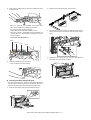
13) Close the drum positioning unit, and tighten the blue screw.
$7'(9($'-B0B<
$7'(9(92B/B.
$7'(9(92B/B&
$7'(9(92B/B0
$7'(9(92B/B<
.
&
0
<
(;(&87(
MEMO: Be sure to select all of the four colors: K, C, M, Y
6)
After the machine completes cycling, exit the simulation mode
by pressing the [CA] key on the main unit.
D. Installation of individual color toner cartridges
* The life of each toner cartridge is as follows:
14) Install the waste toner box.
Black toner cartridge: equivalent to approximately 40K (A4/LT
5%)
Color toner cartridge: equivalent to approximately 18K (A4/LT
5%)
1)
Shake the toner cartridge horizontally several times.
MX-5141FN MX-4140N/4141N/5140N/5141N (MAIN UNIT) 2 – 4
2)
Open the front cabinet, and pull the toner cartridge out slowly
and horizontally.
2)
Detach the LSU cleaning bar from the front cover.
3)
Turn the felt side of the cleaning bar downward and insert it.
Slide it back and forth a few times to clean the LSU dust-proof
glass.
4)
Replace the LSU claning bar to the front cover and attach the
waste toner box. Close the front cabinet.
* Be sure to install the color cartridges to their proper positions. Avoid installation to a different color position.
* Do not forcibly insert the toner cartridge.
Keep holding the cartridge and completely insert it.
* When the machine is transported with the developing unit
removed, be sure to remove the toner cartridge. (If not, toner
may be clogged.)
Color toner cartridge positions
Yellow
Magenta
Cyan
Black
3)
Insert the cartridge securely until it locks.
* Push it until the click sound is heard.
E. Cleaning of LSU's dust-proof glass
* Dust from the transfer belt or shutter or some other adjacent part
may fall onto the LSU during transport or installation. Be sure to
clean the dust-proof glass before checking the image quality.
1)
Open the front cabinet, and remove the waste toner box.
1
2
MX-5141FN MX-4140N/4141N/5140N/5141N (MAIN UNIT) 2 – 5
F. Installation of the operation manual pocket
(2)
1)
1)
Install the Operation Manual storage (Packed items) cover to
the left side of the machine.
a)
First, insert the pawl on the lower side of the Operation
Manual pocket.
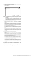
Tray size setup
Pull out the paper tray.
Gently pull the tray out until it stops.
If paper remains in the tray, remove it.
Then, lift the pawl on the upper side and insert it, and slide
down to install.
Adjust the guide plates A and B by squeezing their lock levers
and sliding them to match the vertical and horizontal dimensions of the paper to be loaded.
* If the FINISHER is installed together with installation of the
machine, the Operation Manual storage cover must be
installed to the FINISHER.
The guide plates A and B are slidable. Slide each guide plate
while squeezing its lock lever.
b)
2
2)
1
1
A
B
G. Tray setup
(1) Simulation setup
H. Specifications setup
Change the tray setting in the "system setting" mode. If "Disabling
of Tray Settings" has been enabled in the system settings (administrator), the tray settings (except for the bypass tray) cannot be configured.
Used to set the specifications with SIM26 according to the customer's request.
1)
Enter the SYSTEM SETTING mode.
2)
Touch the [Paper Tray Settings] key.
3)
Touch the [Paper Tray Settings] key to configure the settings.
These settings specify the paper type, paper size, and functions allowed for each paper tray. When the [Tray Settings] key
is touched, a list appears showing the trays and the current
settings.
4)
SIM No
26
Type
Size
Feeding Approved
Job
Description
Select the type of paper that is loaded in the tray.
The paper types that can be selected vary by paper
tray.
Select the paper size from the list. The paper sizes
that can be selected vary by tray. The sizes that
can be selected may also be restricted by the paper
type selected above.
If the desired size does not appear in the list, select
[Custom Size] and directly enter the size (only for
the bypass tray).
Select the modes that can be used. If there is a
function that you do not wish to be used with the
selected tray, disable the function. When the "Type"
is other than plain paper, recycled paper, colored
paper, or a user type, [Fax] and [Internet Fax]
cannot be selected.
Content
Used to set the destination.
To customize the following items after completion of the destination
setup, change the set values.
SIM No
26
Touch the [Change] key in the above screen to change the settings. The following settings can be configured.
Item
6
2
3
5
18
52
53
65
Content
LCC paper size setting
Used to set the auditor specification mode.
Used to set the count mode of the total counter and
the maintenance counter.
Used to set YES/NO of the toner save mode (Only
in UK and Japan versions)
* For other destination versions, this setup is
made by the user program.
Used to set YES/NO of counting when non-print
paper is passed through each counter.
Used to set YES/NO of user calibration permission.
Used to set the limit number of sheets for stapling.
I. Image quality check
(1)
Image loss, void area, image off-center check
Make a copy in the original table mode and in the RSPF/DSPF
mode. Check to confirm that the image loss and the void area are
in the range shown below.
Content
Lead edge void area
Rear edge void area
FRONT/REAR void area
Lead edge image loss adjustment
Side image loss adjustment
MX-5141FN MX-4140N/4141N/5140N/5141N (MAIN UNIT) 2 – 6
Standard adjustment value
3.01.0mm
2.0 - 5.0mm
2.02.0mm
3.01.0mm
2.01.0mm
3.
Image quality check
2)
A. Execution items
Execute the following items.
No.
1
2
3
4
Press [EXECUTE] key.
[EXECUTE] key is highlighted and the image registration automatic adjustment is started. (It takes about 15 sec to complete
the adjustment.)
Item
Print engine image distortion adjustment (Manual
adjustment) / OPC drum phase adjustment
(Automatic adjustment) / Color registration
adjustment (Automatic adjustment)
Copy color balance and density check
Printer color balance/density check
Copy/Printer color balance and density adjustment
(Automatic adjustment)
SIM
50-22
3)
When the adjustment is completed, [EXECUTE] key returns to
the normal display, and the value of the adjustment result is
displayed.
The current skew level for each color is displayed on the
SKEW display section.
64-5/67-25
46-74
B. Description
(1) Print engine image distortion adjustment (Manual
adjustment) / OPC drum phase adjustment
(Automatic adjustment) / Color registration
adjustment (Automatic adjustment)
This adjustment performs the print engine image distortion adjustment, the OPC drum phase adjustment, and the color registration
adjustment simultaneously.
1)
Enter SIM50-22 mode.
ǂǂǂ6,08/$7,21ǂǂ12
7(67
&/26(
$872$'-8670(172)5(*,675$7,21'580326,7,21
0$,1)0$,1568%6.(:3+$6(
&/1*
0/1*
</1*
$//B527$7(/
(;(&87(
EXECUTE
Adjustment completed
ǂǂǂ6,08/$7,21ǂǂ12
7(67
&/26(
$872$'-8670(172)5(*,675$7,21'580326,7,21
12:(;(&87,1*
(;(&87(
Abnormal end
ǂǂǂ6,08/$7,21ǂǂ12
7(67
&/26(
$872$'-8670(172)5(*,675$7,21'580326,7,21
35(66>(&(;87(@7267$57
(55257211(5(037<
(;(&87(
MX-5141FN MX-4140N/4141N/5140N/5141N (MAIN UNIT) 2 – 7
Display/
Item
MAIN F
Content
C
M
Y
MAIN R
C
M
Y
SUB
C
M
Y
Registration adjustment value main scanning
direction (Cyan laser writing position F side)
Registration adjustment value main scanning
direction (Magenta laser writing position F side)
Registration adjustment value main scanning
direction (Yellow laser writing position F side)
Registration adjustment value main scanning
direction (Cyan laser writing position R side)
Registration adjustment value main scanning
direction (Magenta laser writing position R side)
Registration adjustment value main scanning
direction (Yellow laser writing position R side)
Registration adjustment value sub scanning direction
(Cyan drum Black drum)
Registration adjustment value sub scanning direction
(Magenta drum Black drum)
Registration adjustment value sub scanning direction
(Yellow drum Black drum)
Print skew amount calculation result (Cyan)
Print skew amount calculation result (Magenta)
Print skew amount calculation result (Yellow)
SKEW
C
M
Y
PHASE
OPC drum phase adjustment value
4)
Display
Default
1.0 - 199.0
100
1.0 - 199.0
100
1.0 - 199.0
100
1.0 - 199.0
100
1.0 - 199.0
100
1.0 - 199.0
100
1.0 - 199.0
100
1.0 - 199.0
100
1.0 - 199.0
100
-99.9 - 99.9
-99.9 - 99.9
-99.9 - 99.9
0
0
0
1-8
1
Write down the displayed skew level.
(Meaning of the skew level value and the adjustment procedure)
* If "OK" is displayed for all items of C, M, and Y (SKEW),
there is no need to perform the adjustment.
5)
NOTE
If the value is positive (+), "L" is displayed at the head of the
value. If negative (?), "R" is displayed.
If the value is in the range of ?2.1 - +2.1, "(OK)" is displayed at
the bottom of the value. In the other cases, "(NG)" is displayed.
Repeat the procedures 2) to 4) again, and check to confirm
that C, M, and Y (SKEW) are OK.
If any of them is NG, turn the LSU skew adjustment screw of
the corresponding color to adjust.
* When "R" is displayed at the head of the value, turn the LSU
skew adjustment screw clockwise.
* When "L" is displayed at the head of the value, turn the LSU
skew adjustment screw counterclockwise.
Y
M
C
* The turning amount of the adjustment screw corresponds to
each adjustment value. C, M, and Y indicate numbers of
clicks.
The display value is rounded at the decimal point.
* "C, M, and Y(SKEW)" shows the number of adjustment click
steps for each adjustment screw of C, M, and Y.
Contents in (
)
MIAN, SUB: Difference from the previous adjustment value of
image registration.
Example:
If 105 for this time and 103 for the previous time,
it is displayed as 105.0 (+2.0).
NOTE: When an abnormality occurs, "ERROR" is displayed.
In this case, check each drive section and the process section.
SKEW: Judgment of the LSU skew adjustment result. OK or
NG.
PHASE: OPC drum phase adjustment value of the previous
time
MX-5141FN MX-4140N/4141N/5140N/5141N (MAIN UNIT) 2 – 8
(2) Copy color balance and density check
MEMO: Before checking the copy color balance and density, be
sure to execute the following jobs.
* Execute the high density image correction (Process correction)
forcibly. (SIM 44-6)
* Execute the half-tone image correction forcibly. (SIM 44-26)
Method 1
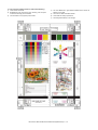
Make a copy of the gray test chart (UKOG-0162FCZZ) and a copy
of the servicing color test chart (UKOG-0326FCZZ/UKOG0326FC11), and check that they are proper.
a. Note for execution of the color balance and density check in the
color copy mode
To check the copy color balance and density, use the gray test
chart (UKOG-0162FCZZ) and the servicing color test chart
(UKOG-0326FCZZ/UKOG-0326FC11). Set the copy density
level to "3" in the Text/Printed Photo mode (Manual), and make a
copy.
At that time, all the color balance adjustments in the user adjustment mode must be set to the default (center).
In addition, be sure to use the specified paper for color.
b. Note for checking the monochrome copy mode density
To check the density, use the gray test chart (UKOG-0162FCZZ).
Set the copy density level to "Manual 3" in the Text/Printed Photo
mode (Manual).
In addition, all the color balance adjustments in the user adjustment mode must be set to the default (center).
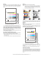
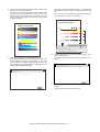
Check with the gray test chart (UKOG-0162FCZZ)
In the copy density check with the gray test chart, check to insure
the following conditions.
NOTE: For the color (gray) balance, use the servicing color test
chart (UKOG-0326FCZZ/UKOG-0326FC11) to check.
(Color copy)
Patch 1 is
slightly copied.
SHARP gray chart
SHARP GRAY CHART
1
2
3
4
5
6
7
8
9
10
W
9
10
W
Patch 2 is copied.
(Black-and-white copy)
Patch 2 is
slightly copied.
1
2
SHARP gray chart
SHARP GRAY CHART
3
4
5
6
7
8
Patch 3 is copied.
Patch 1 is not copied.
Check with the servicing color test chart (UKOG-0326FCZZ/
UKOG-0326FC11)
In the copy color balance check with the servicing color test chart,
check to insure the following conditions.
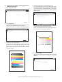
(Color copy)
Serviceman chart (Color patch section)
The densities of patches 1 - 6 of
each color are properly balanced.
Patch 7 is slightly
copied or not copied.
MX-5141FN MX-4140N/4141N/5140N/5141N (MAIN UNIT) 2 – 9
a. Color copy check items (Check to confirm the following:)
1)
There are 12 void areas.
4)
2)
Registrations (one point for the main scanning, and one point
for the sub scanning) are not shifted.
The color difference in gray balance between the F and the R
sides is not so great.
5)
There are no white and black streaks.
3)
The resolution of 5.0 (5 points) can be seen.
6)
Color texts are clearly reproduced.
7)
The background density is not so light.
MX-5141FN MX-4140N/4141N/5140N/5141N (MAIN UNIT) 2 – 10
b. Monochrome copy check items (Check to confirm the following:)
1)
There are 12 void areas.
4)
2)
The resolution of 4.0 (5 points) can be seen.
5)
There are no white and black streaks.
The background density is not so light.
3)
The density difference between the F and the R sides is not so
great.
6)
The black low-density gradation is copied slightly.
MX-5141FN MX-4140N/4141N/5140N/5141N (MAIN UNIT) 2 – 11
Method 2
Method 1
Use SIM46-21 to print the color balance adjustment sheet, and
check each process (CMY) black patch color balance and the black
patch in order to confirm that the color balance adjustment is
proper.
Execute SIM 64-5 to print the print test pattern.
Low
density
NOTE: When the PCL or the PS printer function is not provided in
case of GDI printer, this method cannot be used for check.
Set each set value to the default and press [EXECUTE]
key. The print test pattern is printed.
High
density
Y
M
C
Bk
CMY
blend
A B C D E F G H I J K L M N O P Q
1) The max. density section is not blurred.
2) Patch C or D of each of Y, M, C, and BK is very slightly copied.
The print density must be changed gradually from the lighter level
to the darker level. The density changing direction must not be
reversed. The density level of each color must be almost at the
same level.
Method 2
3) Patch for each of Y, M, C, BK
The patch density is identical between patches or not reversed.
The patch density is changed gradually.
If the color balance of each patch of the process black (CMY mixed
color) is slightly shifted to Magenta, it means that the adjustment is
proper. If the color balance of the adjustment pattern printed in this
mode is slightly shifted to Magenta, it is converted into the natural
gray color balance by the color table in an actual copy mode.
(When the color balance target is DEF 1.)
When the PCL or the PS printer function is not provided (GDI
model), use this method for check.
Use SIM 67-25 to print the color balance adjustment sheet and
compare each process (CMY) black patch color balance and the
black patch to check the color balance.
PRINTER CALIBRATION
If color balance or density is not satisfied, adjust the copy and
printer color balance by SIM 46-74.
(3) Printer color balance/density check
Low density
High density
Y
MEMO: Before checking the printer color balance and the density,
be sure to execute the following procedures in advance.
M
* Execute the high density image correction (Process correction)
forcibly. (SIM 44-6)
C
* The half-tone image correction is forcibly executed. (SIM 44-26)
Bk
CMY
blend
A B C D E F G H I J K L M N O P Q
1) The max. density section is not blurred.
2) Patch C or D of each of Y, M, C, and BK is very slightly copied.
3) Patch for each of Y, M, C, BK
The patch density is identical between patches or not reversed.
The patch density is changed gradually.
The print density must be changed gradually from the lighter level
to the darker level. The density changing direction must not be
reversed.
The density level of each color must be almost at the same level.
Patch B may not be copied.
Patch A must not be copied.
If the color balance of each patch of the process black (CMY mixed
color) is slightly shifted to Magenta, it means that the adjustment is
proper. In an actual print mode, it is converted into the natural gray
color balance by the color table. (When the color balance target is
DEF 1.)
MX-5141FN MX-4140N/4141N/5140N/5141N (MAIN UNIT) 2 – 12
(4) Copy/Printer color balance and density adjustment
(Automatic adjustment)
1)
4)
Enter the SIM46-74 mode.
ǂǂǂ6,08/$7,21ǂǂ12
7(67
Select [FACTORY] target, and press [EXECUTE] key.
When the color balance is customized by the manual color balance adjustment (SIM 46-21) according to the user's request,
and the color balance is registered with SIM63-7 as the service
target, if the color balance is required to be adjusted, select the
[SERVICE] target.
&/26(
(1*,1($872$'-8670(176(59,&(
35(66>(;(&87(@72352&21(;(&87,21$1'35,177+(7(673$7&+
ǂǂǂ6,08/$7,21ǂǂ12
7(67
3/($6(86(63(&,),('7<3(2)$$25;;6,=(3$3(5
&/26(
(1*,1($872$'-8670(176(59,&(
)257+,6$'-8670(17
3/($6(6(/(&77+(02'()$&725<256(59,&($1'3/$&(
7+(35,17('7(673$7&+21'2&80(17*/$667+(135(66>(;(&87(@
/,*+7$5($$7/()76,'(21'2&80(17*/$66
(;(&87(
2)
Press [EXECUTE] key.
)$&725<
The high density process control is performed, and the copy
color patch image (adjustment pattern) is printed out.
(A4/11" x 8.5" or A3/11" x 17" paper is automatically selected.)
(;(&87(
The copy color balance adjustment is automatically executed
and prints the color balance check patch image.
If there is any streak or unclear print on the printed check pattern, check the print engine for any problems.
ǂǂǂ6,08/$7,21ǂǂ12
7(67
6(59,&(
&/26(
(1*,1($872$'-8670(176(59,&(
352&21(;(&87,1*
Low
density
High
density
Y
M
(;(&87(
3)
C
Set the color patch image (adjustment pattern) paper printed in
procedure 2) on the document table.
Bk
Set the color patch image (adjustment pattern) printed in the
procedure 2) on the document table. Place the color patch
image so that the fine lines are on the left side. At that time,
place 5 sheets of white paper on the printed color patch image
(adjustment pattern).
A B C D E F G H I J K L M N O P Q
5)
Press [EXECUTE] key.
The printer color patch image (adjustment pattern) is printed
out. (A4/11" x 8.5" or A3/11" x 17" paper is automatically
selected.)
ǂǂǂ6,08/$7,21ǂǂ12
7(67
&/26(
(1*,1($872$'-8670(176(59,&(
&21),507+($'-3$7&+$1'35(66>(;(&87(@72$'-2)5(*,675$7,21(;(
$1'35,177+(7(673$7&+
3/($6(86(63(&,),('7<3(2)$25h6,=(3$3(5
)257+,6$'-8670(17
(;(&87(
MX-5141FN MX-4140N/4141N/5140N/5141N (MAIN UNIT) 2 – 13
6)
The printer color balance adjustment (step 1) is automatically
performed and the color balance check patch image is printed
out.
Set the color patch image (adjustment pattern) printed in the
procedure 5) on the document table.
Set the color patch image (adjustment pattern) printed in the
procedure 2) on the document table. Place the color patch
image so that the fine lines are on the left side. At that time,
place 5 sheets of white paper on the printed color patch image
(adjustment pattern).
If there is any streak or unclear print on the printed check pattern, check the print engine for any problems.
PRINTER CALIBRATION
PRINTER CALIBRATION
Low density
High density
;
/
%
$M
# $ % & ' ( ) * + , - . / 0 1 2 3
1) The max. density section is not blurred.
2) Patch C or D of each of Y, M, C, and BK is very slightly copied.
3) Patch for each of Y, M, C, BK
The patch density is identical between patches or not reversed.
The patch density is changed gradually.
8)
7)
Select [FACTORY] target, and press [EXECUTE] key.
The initial setting menu of the half tone image correction is displayed. Press [OK] key.
The initial setting of the half tone image correction is performed.
When the color balance is customized with the manual color
balance adjustment (SIM 67-25) according to the user's
request and the color balance is registered as the service target with SIM 67-27, if the color balance is adjusted to that color
balance, select the [SERVICE] target.
ǂǂǂ6,08/$7,21ǂǂ12
7(67
&/26(
(1*,1($872$'-8670(176(59,&(
&21),507+($'-867('3$7&+$1'35(66>2.@725(*,67(57+,63$7&+'$7$
ǂǂǂ6,08/$7,21ǂǂ12
7(67
&/26(
(1*,1($872$'-8670(176(59,&(
3/($6(:$,7
12:5(*,67(5,1*7+(1(:7$5*(72)+$/)721(352&2167
2.
9)
2.
Wait until [EXECUTE] key is displayed. When it is displayed,
press it.
The half tone image correction is performed.
MX-5141FN MX-4140N/4141N/5140N/5141N (MAIN UNIT) 2 – 14
10) When "COMPLETED THIS PROCEDURE" is displayed, the
adjustment operation is completed.
Cancel SIM46-74.
ǂǂǂ6,08/$7,21ǂǂ12
7(67
&/26(
(1*,1($872$'-8670(176(59,&(
&203/(7(7+,6352&('85(
3/($6(48,77+,602'(
2.
5(68/7
5(75<
NOTE: The adjustment result becomes valid only when the both
adjustments in the copy mode and in the printer mode are
completed.
For example, if the copy color balance adjustment (automatic adjustment) is performed and the simulation is canceled, the adjustment result is invalid.
11) Check the copy color balance and density.
(Refer to the item of the copy color balance and density
check.)
When satisfactory color balance and density are not obtained
from the automatic adjustment by selecting the factory target in
procedure 4), change the factory color balance target with SIM
63-11 and repeat the procedures from 1).
If a satisfactory result is not obtained with the above procedure, perform the manual color balance adjustment (ADJ 10C
(2)).
Also when the service target is selected in procedure 4) to execute the automatic adjustment and a satisfactory result is not
obtained, perform the manual color balance adjustment (ADJ
10C (2)).
12) Check the printer color balance and density.
(Refer to the item of the printer color balance and density
check.)
When satisfactory color balance and density are not obtained
from the automatic adjustment by selecting the factory target in
procedure 7), change the factory color balance target with SIM
67-26 and repeat the procedures from 1).
If a satisfactory result on the color balance and the density is
not obtained with the automatic adjustment, execute the manual adjustment (SIM 67-25) (ADJ 10E (2)).
Also when the service target is selected in procedure 7) to execute the automatic adjustment and a satisfactory result is not
obtained, perform the manual color balance adjustment (ADJ
10E (2)).
If the color balance or density is not in the satisfactory level even
after execution of the automatic and manual adjustments, there
may be another cause.
Troubleshoot the cause, repair or perform necessary works, and
repeat the adjustment from the beginning.
MX-5141FN MX-4140N/4141N/5140N/5141N (MAIN UNIT) 2 – 15