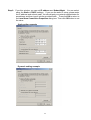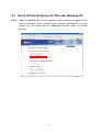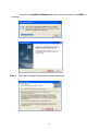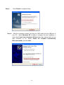
1
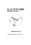
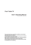
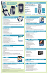
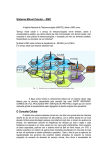
VCTnet AirXpress UC11B
USB Wireless Network Adapter
Installation and Getting Started Guide
Version 2.00
Copyright © 2002, Zida Technologies Ltd. All rights reserved
Other product and corporate names are trademarks of other companies and are used only for explanation and to the owner’s
benefit.
Disclaimer
The information contained in this document is subject to change without notice.
Zida Technologies Ltd. assumes no responsibility for errors or omissions in this manual.
Safety
Before installing and operating the products, please read through this Manual first.
2
Table of Contents
1
2
3
3.1
3.2
4
4.1
4.2
4.3
4.4
Introduction .......................................................................................4
Wireless LAN Basics.........................................................................5
About the Hardware ..........................................................................6
Know about the AirXpress UC11B Wireless Network Adapter ......6
To Use of the Wall Mount Kit .........................................................7
Windows Installation .........................................................................8
Install VCTnet AirXpress UC11B under Windows 98/ME ..............10
Install VCTnet AirXpress UC11B under Windows 2000 ................18
Install VCTnet AirXpress UC11B under Windows XP....................25
Configuration Utility under Windows 98/ME/2K/XP .......................38
Appendix A
Appendix B
Appendix C
Appendix D
Technical Specifications......................................45
FCC Information ..................................................46
Regulatory Information........................................47
Quick Troubleshooting Guide ..............................48
3
1 Introduction
Thank you for purchasing the VCTnet AirXpress UC11B USB Wireless
Network Adapter. With VCTnet AirXpress products, you are about to enter
the world of Wireless Local Area Network (WLAN) to enjoy a network cable
free working environment..
With using the radio frequency (RF) technology, WLANs transmit and
receive data over the air, minimizing the need for wired connections. Thus,
WLANs combine data connectivity with user mobility, and, through
simplified configuration, enable movable LANs.
This wireless networking solution has been designed for both large and
small businesses, and it is scalable so that you can easily add more users
and new network features as your business grows.
This manual will assist you in the installing VCTnet AirXpress UC11B
USB Wireless Network Adapter.
4
2 Wireless LAN Basics
The Wireless LAN defined by IEEE 802.11b standard committee could be
configured as:
• Ad Hoc wireless LAN or
• Infrastructure wireless LAN
Ad Hoc wireless network is a group of PCs installed with the Wireless PCMCIA
card, e.g. VCTnet AirXpress PC11B, or USB Wireless Network Adapter, e.g. VCTnet
Airpress UC11B, to compose a Basic Service Set (BSS). The PCs in the same BBS
communicate with each other directly with the WLAN devices.
STA 2
STA 1
STA 3
Figure 2-1 Ad Hoc wireless network
The most obvious differentiation between Infrastructure wireless network and
Ad Hoc wireless network is that the notebooks in Infrastructure wireless network can
make use of the resource in the Internet through Access Point.
Access Point
Internet
STA 1
STA 3
STA 2
Figure 2-2 Infrastructure wireless network
To set up your notebook’s network as the type of “Ad Hoc” or “Infrastructure”
wireless network depends completely on your requirement. Generally, if your network
environment has an Access Point, we recommend that you set it as “Infrastructure”
to connect to the Internet.
5
3 About the Hardware
3.1 Know about the AirXpress UC11B Wireless Network
Adapter
The following picture shows a AirXpress UC11B Wireless Network USB Adapter.
With reference to the picture, it shows different part of the unit.
Antenna
ACT LED
Power LED
USB Port
Antenna -
it helps to receive and transmit the RF Signal. With adjusting the
position of the antenna, it would improve signal quality.
ACT LED - this LED will blink when data is being transmitted or received.
Power LED - this LED lights up when power is connected.
USB Port - to plug the attached USB cable to the Adapter and the other end of the
USB cable to the USB port of the PC.
6
3.2 To Use of the Wall Mount Kit
A wall mount kit comes with the AirXpress UC11B USB Wireless Network Adapter.
With the wall mount kit, the adapter can be attached onto the wall or any other vertical
surface, such as chassis of monitor, to have better reception.
Step 1: Remove the adhesive strip of
velcro and attach it to the wall or the
vertical surface where the Wireless
Network Adapter will mount on.
Step 2: To install the UC11B Adapter to
the Wall Mount Kit, just simply slide the
UC11B Adapter into the Wall Mount Kit as
the direction shown.
Wall Mount Kit of the UC11B USB
Wireless Network Adapter
7
4 Windows Installation
This section describes the procedures for installing the VCTnet AirXpress UC11B
Wireless Network Adapter under Windows 98, ME, 2000, and XP operating systems.
Before You Start
Before the installation, please check your system in advance and ensure it meets
the minimum requirements as described below:
- Processor: Intel Celeron / Pentium II /Pentium III / Pentium IV; AMD Duron /
Athlon or above
- Operating System: Microsoft Windows 98 / ME / 2000 / XP/ Linux
- System memory: 32MB minimum
- Hard Drive Free Space: 5MB
Note: To prevent potential problems during installation, please run the
installation tool from the CD to finish the driver installation before you
plug the UC11B wireless network adapter into the computer.
To use the UC11B, the system must be has an available USB port. All drivers
and the supporting software for the UC11B must be installed and configured.
Ask your system administrator for the following information, which you may need
during driver installation:
•
•
•
•
Your Wireless LAN SSID.
Your computer’s unique client name and workgroup name
For your network account, your user name and password.
Your IP address, gateway address, and subnet mask, if you’re not using a
DHCP server.
Every computer on a network is identified by a unique network address. There
are two methods to assign network addresses to computers on a TCP/IP network:
• Static IP addressing
• Dynamic IP addressing (DHCP)
8
In networks with static IP addressing, the network administrator manually
assigns an IP address to each computer. Once a static IP address is assigned, a
computer uses the same IP address every time it reboots and logs on to the network.
You may manually change the IP address in the Network Properties dialog box.
Networks using static IP addresses are easy to set up and do not require additional
network management software.
In networks with dynamic IP addressing, a DHCP server in the network
dynamically assigns IP addresses to all its clients every time they log onto the network.
Network using dynamic IP addresses require setting up and running a DHCP Server.
Installation Menu
After you insert the VCTnet CD, the welcome screen will appear. Note: If the
welcom screen window doesn’t appear automatically, you can browse the CD
content and run “setup.exe” manually from the UC11B directory.
9
4.1 Install VCTnet AirXpress UC11B under Windows 98/ME
Step 1
Insert the VCTnet CD, and the welcome menu will appear. If the
welcome menu window doesn’t appear automatically, you can browse the
CD content and run setup.exe manually under the UC11B directory.
10
Click on “UC11B – USB Wireless Network Adapter”. It opens the “AirXpress
Wireless LAN” selection screen, click on “Install UC11B Driver and Utilities” to
start the installation process.
When prompt for File Download, click the “Open” button to start the Install Shield.
11
Once InstallShield Wizard dialog box is shown. Click the NEXT button to
continue.
Step 2. Click Yes to accept the software license agreement.
12
Step 3. The Install Shield will start copying files into your system.
Step 4. Click Finish to complete the Setup process. The PC will then restart.
Step 5. After the computer restarts, just plug the USB cable into the USB port of your
PC. Windows 98 will automatically detect the UC11B, briefly opens a New
Hardware Found window, and starts collecting information for a driver
information database.
13
Step 6. After the hardware wizard finds the installation files, it displays the search
results. Click Next to allow windows to copy the necessary files.
Step 7. Windows start copying the necessary files into your system.
14
Step 8. The Add New Hardware Wizard window appears noting that Windows has
finished installing the software that your new hardware device requires.
Click Finish.
Step 9. The Restart Computer dialog appears, remove the VCTnet CD and click Yes
to restart the computer.
15
Step 10. After the computer restarts, double-click the My Computer icon on your
desktop. In My Computer window, double click the Control Panel icon.
In Control Panel window, double click the Network icon.
Step 11.
Highlight the TCP/IP->11Mbps Wireless LAN USB Dongle for setting
the IP address. Click Properties.
16
Step 12. You can assign IP address and Subnet Mask from this window. You can
select either Static or Dynamic setting. If you choose the static IP setup,
please enter the IP address and Subnet mask. You should ask your network
administrator for an address, and then type it into the blank boxes as below.
Then click OK to return to the Network dialog box. Then click OK button to
set the value.
Static Setting Example
Dynamic Setting Example
17
4.2 Install VCTnet AirXpress UC11B under Windows 2000
Step 1.
Insert the VCTnet CD, and the welcome menu window will appear. If the
welcome menu window doesn’t appear automatically, you can browse the
CD content and run setup.exe manually under the UC11B directory.
18
Click on “UC11B – USB Wireless Network Adapter”. It opens the “AirXpress
Wireless LAN” selection screen, click on “Install UC11B Driver and Utilities” to
start the installation process.
When prompt for File Download, click the “Open” button to start the Install Shield.
19
The InstallShield Wizard dialog box appears as shown below. Click NEXT to
continue.
Step 2.
Click Yes to accept the Software License Agreement.
20
Step 3. Click Finish to complete the installation process.
Step 4. After the computer restarts, just plug the USB cable into the USB port of your
PC. Windows 2000 will automatically detect the USB Dongle, a New
Hardware Found window pops up.
Click Yes in the Digital Signature dialog box.
21
Step 5. Then click Start menu and select Settings. Choose the Control Panel.
Double click the Network and Dial-up Connections icon in the Control
Panel.
Step 6. Click the local area connection icon.
22
Step 7.
Double-click the Properties button to configuration network protocol.
Step 8. Select Internet Protocol (TCP/IP) and click Properties
23
Step 9. From this window, you can set IP address and Subnet Mask. You can select
either the Static or DHCP settings. If you use the static IP setup, please enter
the IP address and subnet mask. You should ask your network administrator for
an address, and then type it into the provided fields. Then click OK to return to
the Local Area Connection Properties dialog box. Then click OK button to set
the value.
Static setting example
Dynamic setting example
24
4.3 Install VCTnet AirXpress UC11B under Windows XP
Step 1 Insert the VCTnet CD, and the welcome menu window will appear. If the
auto-run welcome menu window doesn’t appear automatically, you can
browse the CD content and run setup.exe manually under the UC11B
directory.
25
Click on “UC11B – USB Wireless Network Adapter”. It opens the “AirXpress
Wireless LAN” selection screen, click on “Install UC11B Driver and Utilities” to
start the installation process.
When prompt for File Download, click the “Open” button to start the Install Shield.
26
It opens the InstallShield Wizard dialog box as shown below. Click NEXT to
continue.
Step 2. Click Yes to accept the Software License Agreement.
27
Step 3.
Step 4.
Click Finish to complete Setup.
After the computer restarts, just plug the USB cable into the USB port of
your PC. When Windows XP is ready to configure the new hardware, it
opens the Found New Hardware Wizard dialog box asking what do you
want Windows to do. Select Install the software automatically
(Recommended), and click Next.
28
Windows XP starts to search the driver automatically, and copy the necessary files.
Step 5. When prompt for Hardware Installation, click “Continue Anyway” to
continue the process.
29
Step 6. The Found New Hardware Wizard window appears stating that Windows
has finished installing the software that your new hardware device requires.
Click Finish to end the process.
Step 7.
After the computer restarts, the Network Setup Wizard appears. Click
Next.
30
Step 8.
Click Next again to continue the network setup process.
Step 9. If communication to and from the Internet to all the computers on your
network are sent through this computer , you can choose This computer
connects directly to the Internet. If this computer is part of a home or small
office network that connects to the Internet through another computer on the
network or using a residential gateway, you can choose This computer
connects to the Internet through another computer on my network or
through a residential gateway or other. In this case, choose This computer
connects to the Internet through another computer on my network or
through a residential gateway.
31
Step 10.
A computer name identifies your computer on the network. Some
Internet service providers(ISPs) require that you use a specific computer
name. Check with your ISP to see if they require a specific computer
name. The computer description is a short explanation of the
computer. Type the computer name and computer description then
click Next.
Step 11. Type the Workgroup name then click Next.
Step 12. Click Next.
32
The Network Setup Wizard will perform the necessary setup. It could take up
to a few minutes to finish the setup.
Step 13. Select the Just finish the wizard and click Next.
33
Step 14. Click Finish to end the setup process.
Step 15. Restart the computer.
Step 16. After the computer restarts, click Start menu and select Control Panel.
Double click the Network Connections icon in the Control Panel.
Step 17. Double click the 11Mbps Wireless LAN USB Dongle local area
34
connection icon.
Step 18.
Double click Properties to configuration network protocol.
Step 19. Select Internet Protocol (TCP/IP) and click Properties
35
Step 20. Set IP address and Subnet Mask. You can select either Static or DHCP
setting. If you use the static IP setup then please enter the IP address and
Subnet masking. You should ask your network administrator for an address,
and then type it into the fields provided. Then click OK to return to the
Wireless Network Connection Properties dialog. Then click OK button to set
the value.
Static setting example
36
Dynamic setting example
37
4.4 Configuration Utility under Windows 98/ME/2K/XP
The UC11B uses its own management software. When you insert the UC11B to your system,
the configuration icon
should appear in the Windows System Tray
automatically. If the icon is in red, it means that UC11B configuration is invalid or incomplete.
Double click the icon and the configuration window appear as shown below.
The following options are available.
Status Tab
State
The field shows the association state to available Access Point with
BSSID--MAC address of the Access Point. When the state is “Associated”,
it means normal operation in infrastructure mode and the UC11B is
connected to an Access Point.
Disable Radio
The USB Dongle’s RF radio function can be disabled by clicking this Disable
Radio button.
Rescan
When the Rescan button is clicked, the UC11B will restart the process of
finding an Access point.
Tx/Rx Rate Information
This displays the instantaneous wireless Receive and Transmit throughput in
bytes per second. These values are updated every two seconds.
38
Link Quality / Signal Strength
The Link Quality and Signal Strength bar graph is only active when the node
is in Infrastructure Mode. The bar graph displays the quality and strength of
the link between the node and its Access Point. A label summarizes the
quality of the Link over the bar graph, which can take on one of the following
values:
“Not Applicable”
“Poor”
“Fair”
“Good”
“Excellent”
The driver will start looking for a better Access Point if the Link Quality
becomes “Poor”. Link Quality is a measurement of receiving and transmitting
errors over the radio.
Configuration Tab
The Configuration Tab contains several fields where operating parameters of
the driver can be viewed or changed. Changes to any of the parameters in
this panel can be applied to the driver without a need to restart the computer.
Profile Name
Each Profile represents specific settings of the USB Dongle. You can set the
settings for each profile. Next time when you want to change the USB Dongle
settings, you can just select the profile you want to use.
39
Network Name
Network Name is the group name (or SSID) that will be shared by every
member of your wireless network. You will only be able to connect with an
WLAN device that has the same Network Name.
Network Type
This field allows you to select from a list of supported Network Types. The
types displayed have two values: “Access Point” and “Peer-to-Peer”.
Access Point The infrastructure mode of operation requires the
presence of an 802.11b Access Point. All
communication is done via the Access Point, which
relays packets to other wireless clients in the BSS as
well as to nodes on a wired network such as Ethernet.
Peer-to-Peer This is the 802.11b Ad Hoc mode of operation. All
communication is done from Client to Client without the
use of an Access Point. 802.11 Ad Hoc network uses
the same SSID for establishing the wireless connection.
In this mode you have to set the Channel number you
want to use.
Peer-to-Peer Channel
When you choose Peer-to-Peer as the Network Type, you have to set the
channel number you want to use.
Transmit Rate
The transmission rate at which client of AP transmits the data packets. You
can set this to Auto 1 or 2Mb, 5.5Mb, 11Mb or Fully Automatic.
“OK” button
This button becomes active only when one of the fields has been modified.
Pressing this button applies the changed values to the driver and saves them
to the registry and is used the next time the computer boots up
Encryption Tab
You may want an additional measure of security on your wireless network,
which can be achieved by using WEP (Wired Equivalent Privacy) encryption.
40
WEP encrypts each frame transmitted from the radio using one of the Keys
entered in this panel.
When an encrypted frame is received it will only be accepted if it decrypts
correctly. This will only happen if the receiver has the same WEP Key used
by the transmitter.
To be written to the driver and registry, each key must consist of hex digits,
which means that only digit 0-9 and letter A-F are valid entries.
You can set this to disable, 64 bits or 128 bits.
Encryption WEP – Disabled
The default is Disabled .
Enter Passphrase to Generate Keys Automatically– 64 bit/128bit
You can type a string that you can remember easily in the blank and the WEP
Keys will be generated automatically. There are two options: 64 bit and 128
bit. You can choose any WEP Key from Key 1 to Key 4.
41
Create Keys Manually–64bit/128bit
When you want to entering Keys Manually, there are four fields can be used
and user can choose to use Alphanumeric or Hexadecimal. In
Alphanumeric, you can type the keys between A-Z and numbers arbitrarily.
But in the Hexadecimal, you must type the Hexadecimal symbols. In 64 bit,
the Alphanumeric has 5 characters and the Hexadecimal has 10 digits. And in
the 128 bit, the Alphanumeric has 13 characters and the Hexadecimal has 26
digits. You can choose any WEP Key from Key 1 to Key 4.
42
43
Apply
This button updates the driver with the four keys displayed in Key field.
The keys are also written to the registry for permanent storage.
About Tab
About Tab shows the product version including the detail of Driver,
Configuration Utility, and NIC firmware version. Users must use this version
number when reporting their problems for technical support.
44
Appendix A.
Technical Specifications
Driver Supported
Microsoft Windows 98 / 98 SE / ME / 2000 / XP
Standards Supported
IEEE 802.11b standard for Wireless LAN
Radio Specifications
Frequency Range: 2.4-2.4835 GHz, Direct Sequence Spread Spectrum
Antenna system: External patch antenna
Mobility: Seamless roaming across cell boundaries with handover
Power Specifications
Operating Voltage: 5VDC
Continuous Transmitting: 380 mA (max.)
Continuous Receiving: 320 mA (max.)
Specific Features
Supported bit rates: 1, 2, 5.5, 11Mbps
Number of Channels
North America: CH1-CH11
ETSI: CH1-CH13
France: CH10-CH13
Japan: CH1-CH14
45
Appendix B
FCC Information
FCC Radiation Exposure Statement
This equipment complies with FCC radiation exposure limits set forth for an
uncontrolled environment. This equipment should be installed and operated with
minimum distance 20centimeters between the radiator and your body.
The equipment has been tested and found to comply with the limits for a Class B
Digital Device, pursuant to part 15 of the FCC Rules. These limits are designed to
provide reasonable protection against harmful interference in a residential installation.
This equipment generates, uses and can radiate radio frequency energy and, if not
installed and used in accordance with the instruction, may cause harmful interference
to radio communication. However, there is no grantee that interference will not occur
in a particular installation. If this equipment dose cause harmful interference to radio
or television reception, which can be determined by turning the equipment off and on,
the user is encouraged to try to correct the interference by one or more of the following
measures:
--Reorient or relocate the receiving antenna.
--Increase the separation between the equipment and receiver.
--Connect the equipment into an outlet on a circuit different from that to which the
receiver is connected.
--Consult the dealer or an experienced radio/TV technician for help.
Notice: The Part 15 radio device operates on a non-interference basis with other
devices operating at this frequency. Any changes or modification not
expressly approved by the party responsible could void the user’s authority to
operate the device.
46
Appendix C
Regulatory Information
The AirXpress UC11B USB Wireless Network Adapter must be installed and used in
strict accordance with the manufacturer’s instructions. This device complies with the
following radio frequency and safety standards.
USA - Federal Communications Commission (FCC)
This device complies with Part 15 of FCC Rules. Operation is subject to the following
two conditions:
1. This device may not cause harmful interference, and
2. This device must accept any interference that may cause undesired operation.
Europe - R&TTE Directive
This device complies with the specifications listed below
• ETS 301 489 -1& -17 General EMC requirements for Radio equipment.
• ETS 300 328 Technical requirements for Radio equipment.
• EN 60950 Safety Requirements for Radio equipment
47
Appendix D
Quick Troubleshooting Guide
Symptom:
The power and Act LEDs are off.
Suggestion:
Make sure the USB cable is well-connected to the UC11B USB Wireless Network
Adapter and the PC.
Symptom:
The Wireless Network Adapter icon does not show up in your icon tray after you plug
in the USB port.
Suggestion:
Be sure that the UC11B USB Wireless Network Adapter is not connected to your
computer before executing the Setup.exe from the Installation CD. Otherwise, please
check the USB connection between the PC and the Wireless Network Adapter.
Reboot your computer, if the Setup.exe is executed in first time.
Symptom:
The Wireless Network Adapter icon remains red.
Suggestion:
It means there is no wireless link.
1. Make sure there is any 802.11b device in the servicing area.
2. Double click the icon to pop up the configuration window.
a、 Make sure they are sharing the same SSID and channel. If not, you could
press the Site Survey → Re-Scan to search another nodes in the vicinity.
Then you can select one of them to join.
b、 Make sure they are operating under same authentication type. WEP function
has to be enabled, if Shared Key Authentication is the selection, and the
secret Keys have to be same in the communicating group.
3. Position the antenna to gain the maximum RF power and make sure there is no
metal objects, electron devices or cordless phone in the vicinity.
Symptom:
Slow or erratic performance
Suggestion:
Try change the channel of the communicating group or move your device closer to the
communicating device.
48
Symptom:
The Wireless Network Adapter icon is green, but can’t access wired-LAN.
Suggestion:
1. Make sure there is any 802.11b AP in your LAN.
2. Make sure the Wireless Network Adapter is configured as infrastructure mode.
3. Make sure the Network setting is proper. You could check and modify through My
Computer → Control Panel → Network → TCP/IP / NetBEUI → PRISM2 IEEE
802.11 USB Dongle Adaptor → Content.
Symptom:
The Wireless Network Adapter icon is green, but can’t share files with others.
Suggestion:
Make sure the file and printer sharing function is enabled. You could enable the
function by checking the icon of My Computer → Control Panel → Network → file
and printer sharing → I want to be able to give others to access to my files.
Symptom:
The computer will be down as the USB Wireless Network Adapter is live pulled-out
and plugged-in under Win98 environment.
Suggestion:
Before you live plug in the USB Wireless Network Adapter, be sure the USB Wireless
Network Adapter icon disappears after you pull out it.
Symptom:
The computer seems be halt when the USB Wireless Network Adapter is live
pulled-out and plugged-in more than once under Win98 environment.
Suggestion:
Please wait for more than one minute after USB Wireless Network Adapter is
re-plugged in.
49
Appendix E
Glossary
IEEE 802.11 Standard
The IEEE 802.11 Wireless LAN standards subcommittee, which is formulating a
standard for the industry. The objective is to enable wireless LAN hardware from
different manufacturers to enteropera.
Access Point
An internetworking device that seamlessly connects wired and wireless networks
together.
Ad Hoc
An Ad Hoc wireless LAN is a group of computers, each with a WLAN adapter,
connected as an independent wireless LAN. Ad Hoc wireless LAN is applicable at a
departmental scale for a branch or SOHO operation.
BSSID
A specific Ad Hoc LAN is called a Basic Service Set (BSS). Computers in a BSS must
be configured with the same BSSID.
DHCP
Dynamic Host Configuration Protocol - a method in which IP addresses are assigned
by server dynamically to clients on the network. DHCP is used for Dynamic IP
Addressing and requires a dedicated DHCP server on the network.
Direct Sequence Spread Spectrum
This is the method the wireless cards use to transmit data over the frequency
spectrum. The other method is frequency hopping. Direct sequence spreads the data
over one frequency range (channel) while frequency hopping jumps from one narrow
frequency band to another many times per second.
ESSID
An Infrastructure configuration could also support roaming capability for mobile
workers. More than one BSS can be configured as an Extended Service Set (ESS).
Users within an ESS could roam freely between BSSs while served as a continuous
connection to the network wireless stations and Access Points within an ESS must be
configured with the same ESSID and the same radio channel.
50
Ethernet
Ethernet is a 10/100Mbps network that runs over dedicated home/office wiring. Users
must be wired to the network at all times to gain access.
Gateway
A gateway is a hardware and software device that connects two dissimilar systems,
such as a LAN and a mainframe. In Internet terminology, a gateway is another name
for a router. Generally a gateway is used as a funnel for all traffic to the Internet.
IEEE
Institute of Electrical and Electronics Engineers
Infrastructure
An integrated wireless and wired LAN is called an Infrastructure configuration.
Infrastructure is applicable to enterprise scale for wireless access to central database,
or wireless application for mobile workers.
ISM Band
The FCC and their counterparts outside of the U.S. have set aside bandwidth for
unlicensed use in the so-called ISM (Industrial, Scientific and Medical) band.
Spectrum in the vicinity of 2.4 GHz, in particular, is being made available worldwide.
This presents a truly revolutionary opportunity to place convenient high-speed
wireless capabilities in the hands of users around the globe.
Local Area Network (LAN)
A LAN is a group of computers, each equipped with the appropriate network adapter
card connected by cable/air, that share applications, data, and peripherals. All
connections are made via cable or wireless media, but a LAN does not use telephone
services. It typically spans a single building or campus.
Network
A network is a system of computers that is connected. Data, files, and messages can
be transmitted over this network. Networks may be local or wide area networks.
PCMCIA
Personal Computer Memory Card International Association. Also a PCMCIA card is
also referred to PC Card.
Protocol
A protocol is a standardized set of rules that specify how a conversation is to take
place, including the format, timing, sequencing and/ or error checking.
51
Roaming
In an infrastructure network, this is when a wireless PC moves out of range of the
previously connected access point and connects to a newly connected access point.
Throughout the network environment where access point are deployed, PCs can
always be connected regardless of where they are located or roam.
SSID
A Network ID unique to a network. Only clients and Access Points that share the same
SSID are able to communicate with each other. This string is case-sensitive.
Simple Network Management Protocol (SNMP)
Simple Network Management Protocol is the network management protocol of TCP/IP.
In SNMP, agents-which can be hardware as well as software-monitor the activity in the
various devices on the network and report to the network console workstation. Control
information about each device is maintained in a structure known as a management
information block.
Static IP Addressing
A method of assigning IP addresses to clients on the network. In networks with Static
IP address, the network administrator manually assigns an IP address to each
computer. Once a Static IP address is assigned, a computer uses the same IP
address every time it reboots and logs on to the network, unless it is manually
changed.
Transmission Control Protocol / Internet Protocol (TCP/IP)
TCP/IP is the protocol suite developed by the Advanced Research Projects Agency
(ARPA). It is widely used in corporate Internet works, because of its superior design
for WANs. TCP governs how packet is sequenced for transmission the network. The
term “TCP/IP” is often used generically to refer to the entire suite of related protocols.
Transmit / Receive
The wireless throughput in Bytes per second averaged over two seconds.
Wide Area Network (WAN)
A WAN consists of multiple LANs that are tied together via telephone services and / or
fiber optic cabling. WANs may span a city, a state, a country, or even the world.
52
Wireless LAN (WLAN)
A wireless LAN does not use cable to transmit signals, but rather uses radio or
infrared to transmit packets through the air. Radio Frequency (RF) and infrared are the
commonly used types of wireless transmission. Most wireless LANs use spread
spectrum technology. It offers limited bandwidth, usually under 11Mbps, and users
share the bandwidth with other devices in the spectrum; however, users can operate a
spread spectrum device without licensing from the Federal Communications
Commission (FCC)
53