1
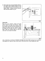
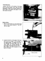
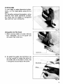
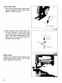
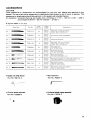
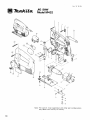
MODEL M432
INSTRUCTION MANUAL
DOUBLE
INSULATION
SPEC1FlCATlONS
Length
of stroke
18 mm
(11116")
Max. cutting capacities
in wood
in steel
Strokes
per minute
Overall
length
Net
weight
50 mm
(2")
6 mm
( 1 /4")
0 - 3.300
190 mm
(7-112")
(3.3Ibs)
Manufacturer reserves the right to change specifications without notice.
Note: Specifications may differ from country to country.
1.5 kg
IMPORTANT
SAFETY INSTRUCTIONS
(For All Tools)
WARNING: WHEN USING ELECTRIC TOOLS, BASIC SAFETY PRECAUTIONS SHOULD ALWAYS BE FOLLOWED TO
REDUCE THE RISK OF FIRE, ELECTRIC SHOCK, AND PERSONAL INJURY, INCLUDING THE FOLLOWING:
READ ALL INSTRUCTIONS.
1. KEEP WORK AREA CLEAN. Cluttered areas and benches invite injuries.
2. CONSIDER WORK AREA ENVIRONMENT. Don't use power tools in damp
3.
4.
5.
6.
7.
8.
9.
IO.
11.
12.
13.
2
or wet locations. Keep work area well lit. Don't expose power tools t o rain.
Don't use tool in presence of flammable liquids or gases.
KEEP CHILDREN AWAY. All visitors should be kept away from work area.
Don't let visitors contact tool or extension cord.
STORE IDLE TOOLS. When not in use, tools should be stored in dry, and
high or locked-up place - out of reach of children.
DON'T FORCE TOOL. It will do the job better and safer at the rate for which
it was intended.
USE RIGHT TOOL. Don't force small tool or attachment t o do the job of
a heavy-duty tool. Don't use tool for purpose not intended.
DRESS PROPERLY. Don't wear loose clothing or jewelry. They can be caught
in moving parts. Rubber gloves and non-skid footwear are recommended
when working outdoors. Wear protective hair covering t o contain long hair.
USE SAFETY GLASSES. Also use face or dust mask i f cutting operation
is dusty.
DON'T ABUSE CORD. Never carry tool by cord or yank it to disconnect from
receptacle. Keep cord from heat, oil, and sharp edges.
SECURE WORK. Use clamps or a vise t o hold work. It's safer than using
your hand and it frees both hands t o operate tool.
DON'T OVERREACH. Keep proper footing and balance at all times.
MAINTAIN TOOLS WITH CARE. Keep tools sharp and clean for better and
safer performance. Follow instructions for lubricating and changing accessories. Inspect tool cords periodically and if damaged, have repaired by
authorized service facility. Inspect extension cords periodically and replace
if damaged. Keep handles dry, clean, and free from oil and grease.
DISCONNECT TOOLS. When not in use, before servicing, and when changing accessories, such as blades, bits, cutters.
14. REMOVE ADJUSTING KEYS AND WRENCHES. Form habit of checking t o
see that keys and adjusting wrenches are removed from tool before turn15.
16.
17.
18.
19.
20.
ing it on.
AVOID UNINTENTIONAL STARTING. Don't carry plugged-in tool with finger
on switch. Be sure switch is OFF when plugging in.
OUTDOOR USE EXTENSION CORDS. When tool is used outdoors, use only
extension cords intended for use outdoors and so marked.
STAY ALERT. Watch what you are doing, use common sense. Don't operate tool when you are tired.
CHECK DAMAGED PARTS. Before further use of the tool, a guard or other
part that is damaged should be carefully checked t o determine that it will
operate properly and perform its intended function. Check for alignment
of moving parts, binding of moving parts, breakage of parts, mounting, and
any other conditions that may affect its operation. A guard or other part
that is damaged should be properly repaired or replaced by an authorized
service center unless otherwise indicated elsewhere in this instruction manual. Have defective switches replaced by authorized service center. Don't
use tool if switch does not turn it on and off.
GUARD AGAINST ELECTRIC SHOCK. Prevent body contact with grounded
surfaces. For example; pipes, radiators, ranges, refrigerator enclosures.
REPLACEMENT PARTS. When servicing, use only identical replacement
parts.
VOLTAGE WARNING: Before connecting the tool t o a power source (receptacle,
outlet, etc.) be sure the voltage supplied is the same as that specified on the
nameplate of the tool. A power source with voltage greater than that specified
for the tool can result in SERIOUS INJURY t o the user - as well as damage t o
the tool. If in doubt, DO NOT PLUG IN THE TOOL. Using a power source with
voltage less than the nameplate rating is harmful t o the motor.
3
ADDITIONAL SAFETY RULES
1. Avoid cutting nails.
operation.
Inspect for and remove all nails from the workpiece before
2. Don't cut hollow pipe.
3. Do not cut oversize workpiece.
4. Check for the proper clearance beneath the workpiece before cutting
blade will not strike the floor, workbench, etc.
SO
that the
5. Hold the tool firmly.
6. Check the blade is not contacting the workpiece before the switch is turned on.
7. Keep hands away from moving parts.
8. When cutting through walls, floors or wherever "live" electrical wires may be encountered, DO NOT TOUCH ANY METAL PARTS OF THE TOOL I Hold the tool
only by the plastic handle to prevent electric shock if you cutting through a "live"
wire.
9. Do not leave the tool running. Operate the tool only when hand-held.
10. Always switch off and wait for the blade to come to e complete stop before removing the blade from the workpiece.
11. Do not touch the blade or the workpiece immediately after operation; they may be
extremely hot end could burn your skin.
SAVE THESE INSTRUCTIONS.
4
HOW TO USE
Mounting Makita jig saw blade
First, use the hex wrench to remove the
bolt which secures the blade clamp to the
blade holder shaft. With the blade teeth
facing forward, place the shank of the
blade over the flat side of the blade holder
shaft. Then place the blade clamp over the
other side of the blade shank. Secure this
assembly together with bolt. Make sure
that the bolt passes through the larger hole
in the blade shank.
Bolt
Fig.
Mounting universal shank jig saw blade
1. I f the universal blade clamp is used, you
can use blades of other makes which
have a universal shank like the one
shown on Fig. 2, with a blade width of
6.35 mm (1/4").
L
Fig.
:
2. Remove the blade clamp using the hex
wrench. Then loosen the bolt on the
universal blade clamp, and fit the universal shank blade onto spring pin inside
the universal blade clamp. (Fig. 3).
Universal
blade clamp
Universal
Spring pin
Universal
shank
blade ( 1 /4")
Fig. :
5
3. Now attach the universal blade clamp to
the blade holder (blade in place) so that
the spring pin fits into the hole on the
blade holder. Tighten the bolt securely
with the hex wrench (Fig. 4).
1
Fig.
Using roller
With the hex wrench, loosen the bolt
which holds the base and retainer. Slide
the retainer so that the roller contacts the
blade, then tighten the bolt. However, when
the blade you use does not have a straight
back, slide the retainer back so that the
roller will not contact the blade.
\
Retatner
I
Fig.
Use a lubricant or cutting oil between the blade and roller when cutting iron or composition board, etc. Failure to do so will shorten the service life of your blade and roller.
6
Switch action
Tool speed is increased by increasing pressure on the trigger. To start the tool, simply
pull the trigger. Release the trigger to stop.
For continuous operation, pull the trigger
and then push in the lock button. To stop
the tool from the locked position, pull the
trigger fully, then release it. A speed control screw is provided so that maximum
tool speed can be limited (variable).Turn
the speed control screw clockwise for
higher speed, and counterclockwise for
lower speed.
Speed
control screw
r
Lock button
Trigger switch
@
Lower
'
M
Fig.
CAUTION :
Before plugging in the tool, always check to see that the trigger switch actuates properly
and returns to the "OFF" position when released.
Operation
Turn the tool on before contacting the
workpiece. Then rest the base flat on the
workpiece and gently move the tool forward along the previously marked cutting
line.
L.-Base
Fig. 7
Plunge cutting
.Starting a cut a t other than the edge of
the workpiece without first drilling a
starting hole requires a "plunge cut". This
can be accomplished by tipping the tool
forward until the front end of the base
rests against the workpiece. Switch the
tool on and lower the back end of the
tool slowly, gradually allowing the blade
to saw through the wood until the base
is able to s i t flat on the workpiece. You
may then proceed forward with the cut in
a normal manner.
0 If using a drill for a starting hole, bore
a hole over 12 mm (1/2") in diameter.
Then insert the blade in it and proceed.
Fig. I
7
Front flush cuts
Loosen the bolt on the back of the base
with the hex wrench, then slide the base
backwards. Check the contact between the
back edge of the blade and support roller,
then secure the bolt.
Fig. 9
Bevel cutting
1. With the base tilted, you can make bevel
cuts a t any angle between 0' and 45'
(left to right).
2. Loosen the bolt on the back of the base
with the hex wrench. Tilt the base to
the desired angle. The edge of the housing indicates the bevel angle. (Fig. 11).
Then check for contact between the
back edge of the blade and the roller.
Now tighten the bolt securely on the
back of the base.
1
I
Edge of housing
Roller
I
1
Fig. 11
8
Finishing edges
To trim edges or make dimensional adjustments, run the blade lightly along the cut
edges.
For smoother cutting of plywoods or other
materials with easily splintered surfaces,
the wood may be coated or transparent
tape used over your cutting line.
Fig. 12
Using guide rule (Rip fence)
1. When cutting widths of under 150 mm
(6") repeatedly, use of the guide rule
will assure fast, clean cuts.
1
1
Fig. 13
2. To attach the guide rule (rip fence), use I
1
the hex wrench to loosen the screw on
the under side of the base in front, slip
in the guide rule and secure the screw.
Hex wrench
Fig. 14
9
Using circular guide
1. Use of the circular guide insures clean,
smooth cutting of circles (radius; under
200 mm; 7-7/8") and arcs.
Circular guide
Fig. l!
2. When attaching the circular guide, use
the pin, inserting it in the center hole
(arrow) and secure it with the threaded
knob. The circular guide attaches to the
base of the tool in the same manner as
the guide rule (rip fence).
Fat pin inlo
Ptn for
ctrcular gulde
Fig. 1(
Metal cutting
Always use a suitable coolant (cutting oil)
when cutting metal. Failure to do so will
cause significant blade wear.
Fig. 17
10
The underside of the work can be greased
instead of using a coolant. (Fig. 18)
I
Fig. 18
11
MAINTENANCE
CAUTION :
Always be sure that the tool is switched off and unplugged before attempting to perform
inspection or maintenance.
The carbon brushes wear out after about 100 hours of operation.
To maintain product SAFETY and RELIABILITY, repairs, maintenance or adjustment
including brush inspection and replacement should be performed by Makita Authorized
or Factory Service Centers, always using Makita replacement parts.
12
ACCESSOR1ES
CAUTION:
These accessories or attachments are recommended for use with your Makita tool specified in this
manual, The use of any other accessories or attachments might present a risk of injury to persons. The
accessories or attachments should be used only in the proper and intended manner.
An exception: Universal shank jig saw blades with a thickness of 1 mm - 1.25 mm (1132'' - 3/64")
and a length of 58 mm - 82 mm (2-9/32" - 3-7/32").
-
Jig saw blade ( 2 per pkg)
I
Blade Type
No.
No 2
No 3
No
No 5
b-
-
No 8
N o 9
No l o
co '' "v'
No 16
pla&cn"nr*
F"
-~
No l 7
I
Part No
I
Teeth
Per Inch
1
I
Applications
723012~3~2
24
80 mm
13 5/32")
Soft steel, non-ferrous metals,
angles. pipe. channels, etc
723009~2.2
14
:;l'im.l
Non-ferrous metals and plastics.
723010 7 2
I
9
I (.&Ty,l I
723008~4~2
723023-8-2
723024
Wood and plywood
8 0 mm
Soft steel, nowferrous metals,
(3~5132"l angles, pipe, channels, etc
723011-5~2
I
I
Overall
Length
I
I
58 mm
Soft steel and
12~9132"l non~ferrous
metals
24
8
1
I
827/32..1
mm
13
1
I
Wood and plywood
For very fast cutting
Wood and plywood
~ ~ ? / ? ~Forl clean and smooth cuts
723025
82 mm
13 7132 )
Wood and plywood For clean and smooth cuts
especially Spllnter free cuts in plywood
79221
82 mm
( 3 7/32 !
Wood and plywood
Ideal for scroll cutting
82 mm
( 3 7/32"!
Nan ferrous metals and plastics
792214~2
l4
Ideal for scroll cutting.
0
Guide rule (Rip fence)
Part No. 164113-2
0
Hex wrench 3
Part No. 783201-2
0
Circular guide assembly
0
Universal blade clamp assembly
Part No. 132276-2
Part No. 123030-5
13
mum
Feb
16 ‘85 EN
JIG SAW
Model M432
Note The s w i t c h . noise suppressor and other part configurations
may differ f r o m c o u n t r y t o c o u n t r y
14
Feh
MODEL M432
,"!,
ILLM
DESCRIPTION
MACHINC
I
2
1
3~
2
1
5
IO
13
14
15
16
I?
IH
19
20
21
22
MACHINE
I
2
1
:
2
1
30
31
32
1
i
1
1
I1
12
DESCRIPTION
1
.
7
8
9
85 US
1
4
6
ILLM
16
1
1
,
,
1
1
,
1
1
39
'
1
1
1
40
l
5
~
~
1
1
1
1
,
1
15
P
MAKITA TWO YEAR LIMITED WARRANTY
FOR HOME USE ONLY
Every Makita tool S
I thoroughly inspected and tested before leaving the factory It is warranted to
be free of defects for a period of two years from the date of original purchase Should any trouble
develop during this t w o year period, return the complete tool, freight prepaid, to one of Makita's
Factory or Authorized Service Centers If inspection shows the trouble IS caused by defective work
manship or material. Makita will repair (or at our option. replace) without charge
This warranty does not apply where
operation of the tool has not been restricted to Home Use
repairs have been made or attempted by others
repairs are required because of normal wear and tear
the tool has been abused, misused or improperly maintained
alterations have been made t o the tool
In no event shall Makita be liable for any indirect. incidental or consequential damages from the
sale or use of the product This disclaimer applies both during and after the term of this warranty
Makita disclaims liability for any implied warranties, including implied warranties of "merchantabili
ty" and "fitness for a specific purpose," after the t w o year term of this warranty
This Warranty gives you specific legal rights, and you may also have other rights which vary from
state to state Some states do not allow the exclusion or limitation of incidental or consequential
damages, so the above limitation or exclusion may not apply to you Some states do not allow limi
tation on how long an implied warranty lasts, so the above limitation may not apply to you
mtlutu"c - -,u,
W
11-8.3-chome. Sumiyorhi-eho, Anjo, Aichi 446, Japan
883447A063
PRINTED IN JAPAN
1986-1 -N