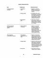
1
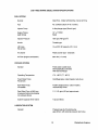
TECHNICAL MANUAL
WESTERBEKE
20B TWO
30B THREE
MARINE DIESEL
PROPULSION ENGINE
Publication #037600
Edition One
April 1990
j
r~ 'WESTERBEKE
J
I
WESTERBEKE CORPORATION· MYLES STANDISH INDUSTRIAL PARK
150 JOHN HANCOCK ROAD, TAUNTON, MA 02780-7319 U.S.A.
SAFETY PRECAUTIONS
Be sure the unit and its surroundings are well-ventilated.
The following symbols appear in this manual to call attention
to and emphasize conditions potentially dangerous to the
operator.
•
Use Extreme Care When Handling Engine Fuel
(A constant danger of explosion or fire exists)
IWARNINGI
Do not fill fuel tank(s) while the engine is running.
The above symbol is used in the manual to warn of possible
serious personal injury or loss of life.
CAUTION
Do not smoke or use an open flame near the engine or the
fuel tank.
•
The above symbol is used in the manual to caution personnel
of possible damage to equipment.
Be sure all fuel supplies have a positive shut-off valve.
Be certain fuel line fittings are adequately tightened and
free of leaks.
Read the manual carefully and thoroughly before attempting
to operate the equipment. Know when dangerous conditions
can exist and take necessary precautions to protect personnel
and equipment.
Fuels, exhaust gases, batteries, electrical equipment, and
moving and hot parts are potential hazards that could result in
serious personal injury or death. Follow recommended procedures carefully.
Make sure a fire extinguisher is installed nearby and is
properly maintained. Be familiar with its proper use. Extinguishers rated ABC by the NFPA are appropriate for all
applications encountered in this environment.
•
Always operate bilge blowers for at least five minutes before
starting a gasoline-fueled engine; ensure no gasoline fumes are
present before starting.
•
Lead acid batteries emit hydrogen, a highly-explosive gas,
which can be ignited by electrical arcing or by a lighted
cigarette, cigar, or pipe. Do not smoke or allow an open
flame near the battery being serviced. Shut off all electrical
equipment in the vicinity to prevent electrical arcing
during servicing.
Shut off electric power before accessing electrical equipment.
Make sure your clothing is dry, not damp (particularly
shoes), and keep your skin surfaces dry when handling
electrical equipment.
Remove wristwatch and jewelry when working on electrical equipment.
Do not connect utility shore power to vessel's AC circuits,
except through a ship-to-shore double-throw transfer
switch. Damage to vessel's AC generator may result if this
is not done.
Be extremely careful when working on electrical components. High voltage can cause injury or death.
Use Extreme Care When Servicing Batterjes
Wear rubber gloves, a rubber apron, and eye protection
when servicing batteries.
Prevent Electric Shock
Use insulated mats whenever working on electrical equipment.
Do Not Alter or Modjfy the Fuel System
•
Avoid Moving Parts
Do not service the unit while the unit is running; if a
situation arises in which it is absolutely necessary to make
operating adjustments, use extreme care to avoid moving
parts and hot exhaust system components.
Do not wear loose clothing or jewelry when servicing
equipment; avoid wearing loose jackets, shirts or sleeves,
rings, necklaces, or bracelets that might be caught in
moving parts.
Make sure all attaching hardware is properly tightened.
Keep protective shields and guards in their respective
place at all times.
Do not check fluid levels or the drive-belt's tension while
the unit is operating.
•
Exhaust Gases Are Toxjc
Ensure that the exhaust system is adequate to expel gases
discharged from the engine. Check exhaust system
regularly for leaks and make sure the exhaust manifolds
are securely attached and no warping exists.
Do not work on the equipment when mentally or physically
incapacitated by fatigue.
IMPORTANT
PRODUCT SOFTWARE DISCLAIMER
Product software of all kinds, such as brochures, drawings, technical data, operator's and workshop
manuals, parts lists and parts price lists, and other information, instructions and specifications provided from
sources other than Westerbeke, is not within Westerbeke's control and; accordingly, is provided to
Westerbeke customers only as a courtesy and service. Westerbeke cannot be responsible for the content
of such software, makes no warranties or representations with respect thereto, including the accuracy,
timeliness or completeness thereof, and will in no event be liable for any type of damages or injury
incurred in connection with, or arising out of, the furnishing or use of such software.
For example, components and subassemblies incorporated in Westerbeke's products and supplied by
others (such as engine blocks, fuel systems and components, transmissions, electrical components, pumps
and other products) are generally supported by their manufacturers with their own software, and Westerbeke
must depend on such software for the design of Westerbeke's own product software. Such software may
be outdated and no longer accurate. Routine changes made by Westerbeke's suppliers, of which Westerbeke rarely has notice in advance, are frequently not reflected in the supplier's software until after such
changes take place.
Westerbeke customers should also keep in mind the time span between printings of Westerbeke product
software and the unavoidable existence of earlier, non-current, Westerbeke software editions in the field.
Additionally, most Westerbeke products include customer-requested special features that frequently do not
include complete documentation.
In summation, product software provided with Westerbeke products, whether from Westerbeke or other
suppliers, must not and cannot be relied upon exclusively as the definitive authority on the respective
product. It not only makes good sense but is imperative that appropriate representatives of Westerbeke or
the supplier in question be consulted to determine the accuracy and currency of the product software being
consulted by the customer.
1
Westerbeke Engines
TABLE OF CONTENTS
Section ......................................................................... Page
20B TWO GENERAL SPECIFICATIONS ............................9
20B TWO SYSTEM SPECIFICATIONS ............................10
30B THREE GENERAL SPECIFICATIONS ...................... 12
30B THREE SYSTEM SPECIFICATIONS ......................... 13
20BTWO AND 30B THREE
ENGINE SERVICE SPECIFICATIONS .............................15
ENGINE OVERHAUL ........................................................23
PREPARATIONS FOR OVERHAUL. .................................24
ENGINE DISASSEMBLY ...................................................25
CYLINDER HEAD CONSTRUCTION
AND SERViCiNG ...............................................................26
VALVES AND VALVE SPRINGS .......................................30
VALVE CLEARANCE ADJUSTMENT ...............................33
GEAR CASE AND OIL PUMP ...........................................34
TIMING GEARS .................................................................38
CAMSHAFTS (Valve and Pump) ......................................41
PISTON AND CONNECTING ROD ..................................45
CRANKSHAFT ...................................................................50
CYLINDER BLOCK ...........................................................54
FUEL INJECTION PUMP ..................................................56
INJECTION NOZZLE ........................................................59
GOVERNOR SYSTEM ......................................................62
GOVERNOR ......................................................................65
GLOW PLUG .....................................................................66
COOLING SYSTEM ..........................................................67
Westerbeke Engines
2
TABLE OF CONTENTS
(CONTINUED)
STARTER .......................................................................... 71
ALTERNATOR .................................................................. 78
ENGINE TROUBLESHOOTING ....................................... 85
MARINE TRANSMISSIONS ............................................. 88
TABLE OF STANDARD
HARDWARE TIGHTENING TORQUES ........................... 89
SPARE PARTS .................................................................. 91
INDEX ............................................................................... 93
3
Westerbeke Engines
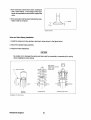
...
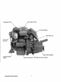
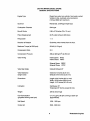
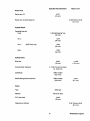
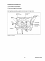
T9PEngine Oil
45° Exhaust Elbow
G:ear Shift Lever
50 Amp DC
Alternator
Gea~ As~~mbly
Adjustable Engine
Isolator
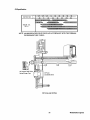
Westerbeke Diesel Engines
Battery Ground Connection
·4
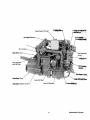
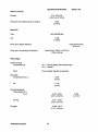
,FreSh W_ Fill CaP~
~
!VI ll'ilake Silenger
Zinc I'\mJUt:i~
Fuellnjeciion~.
Pump
-
.
-
-Gear Dipstick
and Oil Filler
_~~~~e Engine Isolator
5
Westerbeke Engines
.
..
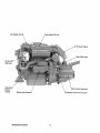
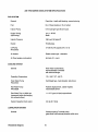
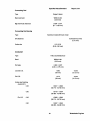
fresh Water Fill Cap
Ge~r
Shift l:,ever
:50 Amp
~t~rnator
AdJU;;'LQU',\;;
:Engine
Isolator
Starter with
Solenoid'
.
-
Westerbeke Engines
DC .Battery Ground Connection
6
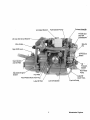
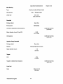
.Air Intake Silel'!cer
.~reh~t Solenord
Fuel Injection Pump
/
ThrotHe and
Shut-Off
Connections
20 Amp DC Circuit
Zinc Anode
Oil Pressure
/SW~l!
Gear Dipstick
and Oil Filler
...
Adjustable Engine
Isolator
. Lube Oil
. Drain Ho~~~
Fresh Water Block Drain Plug
7
Westerbeke Engines
.~
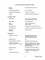
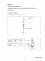
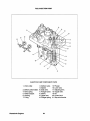
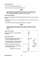
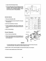
UNIT 1.0. PLATES
•
MODEL
SPEC
.
AVO .. MA USA
SER.NO..
20B TWO UNIT 1.0. PLATE
•
MODEL
SPEC
AVO" MA USA
SER.NO..
30B THREE UNIT 1.0. PLATE
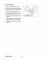
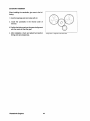
The unit 1.0. plate is attached to the exhaust manifold of the engine. These illustrations are provided so
that the owner/operator may transcribe the specifications and serial number from the 1.0. plate on the
engine to one of the illustrations above. This will allow for easy reference when seeking parts, service or
technical needs.
Westerbeke Engines
8
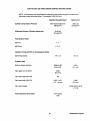
20B TWO MARINE DIESEL ENGINE
GENERAL SPECIFICATIONS
Engine Type
Diesel, four-cycle, two-cylinder, fresh water-cooled.
Vertical, in-line, overhead valve mechanism
(18 hp at 3600 rpm maximum).
Governor
Mechanical, centrifugal weight type.
Combustion Chamber
Swirl type.
Bore & Stroke
2.99 x 2.76 inches (76 x 70 mm)
Piston Displacement
38.75 cubic inches (0.635 liters)
Firing Order
1-2
Direction of Rotation
Clockwise, when viewed from the front.
Maximum Torque (at 2200 rpm)
30 Ib-ft (4.15 kg-m)
Compression Ratio
23:1
Compression Pressure
398 psi (28 kg/cm2 ) at 280 rpm
Valve Timing
Intake Opens BTDC
Intake Closes ABDC
Exhaust Opens BBDC
Exhaust Closes ATDC
Valve Seat Angle
Intake & Exhaust 45°
Valve Clearance
(engine cold)
Intake 0.010 inches (0.25 mm)
Exhaust 0.010 inches (0.25 mm)
Dimensions
Length: 25.87 inches (657.10 mm)
Width: 16.00 inches (406.40 mm)
Height: 19.75 inches (501.65 mm)
Inclination
Continuous 15°
Temporary 25° (not to exceed 30 min.)
Weight
228 Ibs (103.4 kgs)
Fuel Consumption
(propeller allowing rated rpm)
0.7 U.S. gph (2.65lph) running at 2500 rpm
(approximate).
Idle Speed
1000 -1200 rpm
Cruise rpm
2500 - 3000 rpm
9
Westerbeke Engines
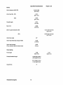
20B TWO MARINE DIESEL SYSTEM SPECIFICATIONS
FUEL SYSTEM
General
Open flow - totally self-bleeding, manual priming.
Fuel
No.2 Diesel (cetane # 45 or better).
Injector Pump
In-line plunger type (Bosch type).
Engine Timing
(spill timing)
19° ±1° BTDC
Static
Injector Pressure
1991 psi (140 kg/cm2)
Nozzle
Throttle type.
Lift Pump
12-volt DC; lift capacity 5 ft (1.5 m)
PN 037818
Air cleaner
Plastic screen type - cleanable.
Air Flow (engine combustion)
40.6 cfm (1.1 cmm)
COOLING SYSTEM
General
Fresh water-cooled block,
thermostatically-controlled
with heat exchanger.
Operating Temperature
170 - 190° F (77 - 88° C)
Fresh Water Pump
PN 037015
Centrifugal type, metal impeller, belt-driven.
Raw Water Pump
PN 033636
Positive displacement, rubber impeller,
mechanically-driven.
Raw Water Flow, at 3600 rpm
(measured before discharging
into exhaust elbow)
11.1 U.S. gpm (42 Ipm) approximate.
System Capacity (fresh water)·
2.9 qts (2.7 liters)
LUBRICATION SYSTEM
General
Westerbeke Engines
Pressure type by Trochoid pump,
gear-driven, with external pressure relief valve.
10
208 TWO MARINE DIESEL SYSTEM SPECIFICATIONS
Oil Filter
PN 036918
Full flow, paper element, spin-on type.
Sump Capacity (including filter)
3.0 U.S. qts (2.9 liters)
Operating Oil Pressure (engine hot)
15 - 45 psi (1.0 - 3.1 kg/cm2 )
Oil Grade
API SPECIFICATION OF CF OR CG-4
ELECTRICAL SYSTEM
Starting Battery
12-volt, 26 A-H, (-) negative ground
(recommended) (35 A-H in cold areas)
Battery Capacity
90 -125 (ampere-hours)
Starter
PN 034552
12-volt, 1.2 t<MI, reduction type,
solenoid-mounted.
DC No-Load Current
100 amp (max.) at 11.5 volts (3000 rpm, min.).
DC Cranking Current
125 amps at 10 volts (805 rpm, min.) (engine cold).
DC Alternator
PN 030594
12 volt DC, 50 amps
TRANSMISSION
General (JS Transmission)
Case hardened helical gears with an
intermediate reverse gear. Reversing
out by a servo double disc system.
Standard Gear Ratio
2.47:1
Propeller Shaft Direction of Rotation
Right handed - standard transmission.
Propeller Recommendations
(using JS transmission 2.47:1 reduction)
150 x 10 P - 2 blade or 15 D x 8 P - 3 blade.
Propeller should allow the engine to reach its
full rated rpm (3600 + 000 - 100) at full open
throttle while underway.
Lubricating Oil Grade
API SPECIFICATION OF CF OR CG-4
SAE Grade
SAE 20W/20 or SAE 30 exclusively. (Do not
mix grades of oil or use multigrade oils!)
Transmission Sump Capacity
1 qt (1 liter)
11
Westerbeke Engines
30B THREE MARINE DIESEL ENGINE
GENERAL SPECIFICATIONS
Engine Type
Diesel, four-cycle, three-cylinder, fresh water-cooled.
Vertical, in-line, overhead valve mechanism
(27 hp at 3600 rpm maximum).
Governor
Mechanical, centrifugal weight type.
Combustion Chamber
Swirl type.
Bore & Stroke
2.99 x 2.76 inches (76 x 70 mm)
Piston Displacement
59.09 cubic inches (0.952 liters)
Firing Order
1-3-2
Direction of Rotation
Clockwise, when viewed from the front.
Maximum Torque (at 2200 rpm)
43 Ib-ft (5.9 kg-m)
Compression Ratio
23:1
Compression Pressure
398 psi (28 kg/cm2) at 280 rpm
Valve Timing
Intake Opens BTDC
Intake Closes ABDC
Exhaust Opens BBDC
Exhaust Closes ATDC
Valve Seat Angle
Intake & Exhaust 450
Valve Clearance
(engine cold)
Intake 0.010 inches (0.25 mm)
Exhaust 0.010 inches (0.25 mm)
Dimensions
Length: 28.81 inches (731.77 mm)
Width: 16.00 inches (406.40 mm)
Height: 19.75 inches (501.65 mm)
Inclination
Continuous 150
Temporary 250 (not to exceed 30 min.)
Weight
272 Ibs (123.3 kgs)
Fuel Consumption
(propeller allowing rated rpm)
1.0 U.S. gph (3.78 Iph) running at 2500 rpm
(approximate).
Idle Speed
1000 -1200 rpm
Cruise rpm
2500 - 3000 rpm
Westerbeke Engines
12
30B THREE MARINE DIESEL SYSTEM SPECIFICATIONS
FUEL SYSTEM
General
Open flow - totally self-bleeding, manual priming.
Fuel
No.2 Diesel (cetane # 45 or better).
Injector Pump
In-line plunger type (Bosch type).
Engine Timing
(spill timing)
19° ±1° BTDC
Static
Injector Pressure
1991 psi (140 kg/cm~
Nozzle
Throttle type.
Lift Pump
PN 037818
12-volt DC; lift capacity 5 ft (1.5 m)
Air cleaner
Plastic screen type - cleanable.
Air Flow (engine combustion)
60.4 cfm (1.7 cmm)
COOUNG SYSTEM
General
Fresh water-cooled block,
thermostatically-controlled
with heat exchanger.
Operating Temperature
170 - 190° F (77 - 88° C)
Fresh Water Pump
PN 037015
Centrifugal type, metal impeller, belt-driven.
Raw Water Pump
PN 033636
Positive displacement, rubber impeller,
mechanically-driven.
Raw Water Flow, at 3600 rpm
(measured before discharging
into exhaust elbow)
11.1 U.S. gpm (42 Ipm) approximate.
System Capacity (fresh water)
4 qts (3.8 liters)
LUBRICATION SYSTEM
General
Pressure type by Trochoid pump,
gear-driven, with external pressure relief valve.
13
Westerbeke Engines
30B THREE MARINE DIESEL SYSTEM SPECIFICATIONS
Oil Filter
PN 036920
Full flow, paper element, spin-on type.
Sump Capacity (including filter)
3.7 U.S. qts (3.5 liters)
Operating Oil Pressure (engine hot)
15 - 45 psi (1.0 - 3.1 kg/cm2 )
Oil Grade
API SPECIFICATION OF CF OR CG-4
ELECTRICAL SYSTEM
Starting Battery
12-volt, 26 A-H, (-)negative ground
(recommended) (35 A-H in cold areas)
Battery Capacity
90 - 125 (ampere-hours)
Starter
PN 034552
12-volt, 1.2 KW, reduction type,
solenoid-mounted.
DC No-Load Current
100 amp (max.) at 11.5 volts (3000 rpm, min.).
DC Cranking Current
190 amps at 10 volts (805 rpm, min.) (engine cold).
DC Alternator
PN 030594
12 volt DC, 50 amps
TRANSMISSION
General (JS Transmission)
Case hardened helical gears with an
intermediate reverse gear. Reversing
out by a servo double disc system.
Standard Gear Ratio
2.47:1
Propeller Shaft Direction of Rotation
Right handed - standard transmission.
Propeller Recommendations
(using JS transmission 2.47:1 reduction)
16 D x 10 P - 2 blade or 16 D x 8 P - 3 blade.
Propeller should allow the engine to reach its
full rated rpm (3600 + 000 - 100) at full open
throttle while underway.
Lubricating Oil Grade
API SPECIFICATION OF CF OR CG-4
SAE Grade
SAE 20W/20 or SAE 30 exclusively. (Do not
mix grades of oil or use multigrade oils!)
Transmission Sump Capacity
1 qt "(1 liter)
Westerbeke Engines
14
20B TWO AND 30B THREE ENGINE SERVICE SPECIFICATIONS
NOTE: All dimensions and specifications contained in this section are given in inches then
millimeters unless otherwise stated. For example, 0.002 (0.5 mm).
Specified Value/Standard
Repair Limit
398.16 psi (at 280 rpm)
(28 kg/cm~
355.5 psi
(25 kg/cm2)
Cylinder Compression Pressure
Difference Between Cylinders (maximum)
35.55 psi
(2.5 kg/cm~
Fuel Injection Order
20BTwo
1-2
30B Three
1-3-2
Injection Timing at BTDC on Compression Stroke
Spill timing (static)
19° ±1.5
Cylinder Head
Bottom surface distortion
Within 0.002
(0.05 mm)
Valve guide 1.0. (IN & EX)
0.260
(6.6 mm)
Valve seat angle (IN & EX)
45°
Valve seat width (I N & EX)
0.051 - 0.071
(1.3 -1.8 mm)
Valve seat sinkage
0.004
(0.1 mm)
0.098
(2.5 mm)
-0.039 (Service limit)
(-1 mm)
Valve Clearance (IN and EX)
0.010 (cold)
0.25
15
Westerbeke Engines
Specified Value/Standard
Repair Limit
Valves
Valve clearance (IN & EX)
0.010 (cold)
(0.25 mm)
Valve head dia. (IN)
1.051
(26.7 mm)
(EX)
0.972
(24.7 mm)
Overall length
3.701
(94 mm)
StemO.D.
0.260
(6.6 mm)
Stem to guide clearance (IN)
1.051 (Service limit)
(26.7 mm)
(EX)
0.972 (Service limit)
(24.7 mm)
Valve face angle
Valve head thickness (margin width)
0.039
(1.0 mm)
Valve head sinkage
(From cylinder head to bottom face)
0.020
0.5mm
Valve Spring
Free length
1.595
(40.5 mm)
Preload/installed length
13.095 Ibs/1.398 in
(5.94 kg/35.5 mm)
32.716 Ibs/1.1 02 in
(14.84 kg/28 mm)
Squareness
Westerbeke Engines
16
1.547
(39.3 mm)
Specified Value/Standard
Repair Limit
Rocker Arm
Rocker arm 1.0.
0.472
(12 mm)
-0.008 (Service limit)
(-0.2 mm)
Rocker arm to shaft clearance
Cylinder Block
Camshaft hole dia.
Front
1.654 Ball bearing hole
(42 mm)
NO.2
No.3
1.339
(34 mm)
(30B Three only)
1.299
(33 mm)
Rear
1.299
(33 mm)
Cylinder Bore
Bore size
Oversize finish tolerance
2.992
(76 mm)
+0.008
(+0.2 mm)
o - 0.001 for each oversize
(0 -0.03 mm)
Cylindricity
Within 0.0004
(0.01 mm)
Gasket fitting/surface distortion
Within 0.0020
(0.05 mm)
0.004
(0.1 mm)
Piston
Type
Solid type
Material
Aluminum alloy
0.0. (skirt end)
2.992
(76 mm)
Clearance to cylinder
0.001 (Service limit)
(0.3 mm)
17
Westerbeke Engines
RepairUmit
Specified Value/Standard
Piston (continued)
0.01, 0.02, 0.03
(0.25, 0.50, 0.75 mm)
Oversize
0.035
(0.9 mm)
Protrusion from cylinder block top surface
Piston Pin
Type
Semi-floating type
0.0.
0.709
(18 mm)
0.003 (Service limit)
(0.08 mm)
Piston pin to piston clearance
Piston pin to connecting rod clearance
Press-fit load: 2204.6 ±1102.3Ibs.
(1000 ±500 kg)
Piston Rings
Number of rings
Compression (2)
Oil (1)
No.1: Chrome plated, semi-keystone type
No.2: Tapered
Chrome plated ring with coil expander
Ring width
Compression (No.2)
0.079
(2mm)
Oil
0.118
(3mm)
Ring side clearance
Compression No. 1
No.2
0.002 - 0.004
(0.05 - 0.09 mm)
Oil ring
0.001 - 0.003
(0.03 - 0.07 mm)
Ring gap
Westerbeke Engines
0.006 - 0.016
(0.15 - 0.40 mm)
18
0.008
(0.2 mm)
Specified Value/Standard
Repair Limit
Connecting Rod
Forged I-beam
Type
Within 0.002
(0.05 mm)
Bend and twist
0.004 - 0.014
(0.1 - 0.35 mm)
Big end thrust clearance
Connecting Rod Bearing
Aluminum metal with back metal
Type
Oil clearance
0.006 (Service limit)
(0.15 mm)
0.01,0.02
(0.25, 0.50 mm)
Undersize
Crankshaft
Type
Fully counterbalanced
Bend
Within 0.001
(0.03 mm)
End play
0.002 - 0.007
(0.05 - 0.175 mm)
Journal 0.0.
1.693
(43 mm)
-0.006
(-0.15 mm)
Pin 0.0.
1.575
(40 mm)
-0.006
(-0.15 mm)
Under size finishing
Journal U.S.
0.25
Pin U.S.
1.6817 - 1.6823
(42.715 - 42.730 mm)
0.50
1.6719 - 1.6724
(42.465 - 42.480 mm)
0.25
1.5636 - 1.5642
(39.715 - 39.730 mm)
0.50
1.5537 - 1.5543
(39.465 - 39.480 mm)
19
Westerbeke Engines
Specified Value/Standard
RepairUmit
Main Bearing
Type
Aluminum metal with back metal
(No.2: Flanged metal)
Oil clearance
0.01,0.02
(0.25, 0.50 mm)
Under size
Camshaft
Gear drive
Driving method
Ball bearing
Front journal
0.006 (Service limit)
(0.15 mm)
Journal to cylinder block hole clearance
1.078
(27.37 mm)
Major diameter of cam (IN and EX)
Oil clearance
0.006 (Service limit)
(0.15 mm)
Injection Pump Camshaft
Driving method
Bearing
Gear drive
Ball bearing (front and rear)
Major diameter of cam
1.18
(30 mm)
Tappet
0.0.
0.75
(19 mm)
Tappet to cylinder block clearance
0.006 (Service limit)
(0.15 mm)
Push Rod
Within 0.0118
(0.3 mm)
Bend
Westerbeke Engines
20
Oil Specification
TEMPERATURE
c"
F"
ENGINE OIL
[SRE I)
-30
-20
-20
o
-10
o
20
Dii' mmmwn
_un
10
40
20
GO
30
80
40
50
100
120
NBI""'' ',!'' ' WhWuj>
NOTE: API SPECIFICATION OF CF OR CG-4 IN ACCORDANCE WITH THE THERMAL
ENVIRONMENT (SEE TABLE).
Oil Pressure Relief Valve
Spring/Plunger Type
Oil Pump
Crankshaft Driven
Oil Pump and Oil Filter
21
Westerbeke Engines
NOTES
Westerbeke Engines
22
ENGINE OVERHAUL
Section ..........................................................................Page
PREPARATIONS FOR OVERHAUL ................................. 24
ENGINE DISASSEMBLY .................................................. 25
CYUNDER HEAD CONSTRUCTION
AND SERVICING .............................................................. 26
VALVES AND VALVE SPRINGS ....................................... 30
VALVE CLEARANCE ADJUSTMENT ............................... 33
GEAR CASE AND OIL PUMP .......................................... 34
TIMING GEARS ................................................................ 38
CAMSHAFTS (Valve and Pump) ...................................... 41
PISTON AND CONNECTING ROD ................................. 45
CRANKSHAFT .................................................................. 50
CYUNDER BLOCK ........................................................... 54
FUEL INJECTION PUMP ................................................. 56
INJECTION NOZZLE ....................................................... 59
GOVERNOR SYSTEM ...................................................... 62
GOVERNOR ..................................................................... 65
GLOW PLUG .................................................................... 66
COOUNG SySTEM .......................................................... 67
STARTER .......................................................................... 71
ALTERNATOR .................................................................. 78
23
Westerbeke Engines
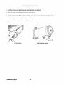
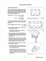
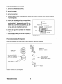
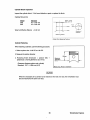
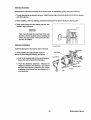
PREPARATIONS FOR OVERHAUL
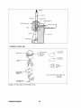
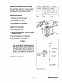
1. Shut off and disconnect all fuel lines, raw water and exhaust connections.
2. Unbolt the engine and carefully move it to the overhaul shop.
3. Once at the overhaul shop, drain all lubricating oil and coolant from the engine and exchanger system.
4. Clean the engine's exterior of all dirt and oil deposits.
~1\1\'\llllllllllIIIIIHl\iI!I"H'iH::~;H~r
1\I,j' \' i'i 'i";',' "
i,'
.
\111.1
:.*'::
I' .
:;"
l
'.
I:
.-
..,,'
.. "
Oil Sump Drain
Westerbeke Engines
Heat Exchanger Drains
24
ENGINE DISASSEMBLY
This section describes the disassembly of the engine when performing a complete overhaul of the unit. The
procedures which follow include the disassembly of subassemblies, inspection of their components parts,
repair or replacement of these parts (if necessary), and the reassembly of the subassemblies.
Removal of External Parts and Subassemblies
1. Remove the exhaust manifold and related hoses as a unit. Disassemble and inspect these parts.
2. Remove the heat exchanger and its related hoses and mounts from the front of the engine. Have the heat
exchanger cleaned and tested at a local automotive radiator repair shop or replace it if necessary.
3. Remove the starter motor and circuit breaker assembly. Examine the starter and have it repaired or
replaced if necessary.
4. Remove the intake silencer, fuel lines, fuel pump and fuel filter with bracket assembly from its attachment
on the bell housing.
5. Remove the high pressure injector lines from between the injection pump and injectors. Note the location
of each line.
6. Remove the transmission bell housing assembly.
7. Remove the raw water pump from its mounting point on the engine.
8. Remove the alternator, the fresh water pump's drive belt, and the alternator's mounting bracket.
9. Remove the fresh water circulating pump's pulley and remove the fresh water pump.
10. Remove the engine's backplate.
11 Remove the water temperature switch and the water temperature sender.
12. Remove the oil pressure switch, the oil pressure sender, and the oil filter.
13. Remove the thermostat housing and the thermostat.
14. Remove the crankshaft pulley from the crankshaft.
The basic engine assembly is now ready for disassembly, cleaning, inspection, and repair if necessary.
25
Westerbeke Engines
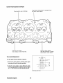
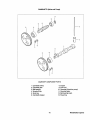
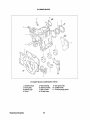
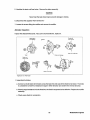
CYLINDER HEAD CONSTRUCTION AND SERVICING
~
~~~
@
.•
~~
~--I'
•.F----J.
-=---ej)
Cylinder head a cross section
CYLINDER HEAD COMPONENT PARTS
1. Cylinder head.
2. Valve guide.
3. Cylinder head bolt (main bolt).
4. Cylinder head bolt (sub-bolt).
5. Seat ring (3600 rpm specification engine).
Westerbeke Engines
26
6. Water outlet fitting.
7. Cylinder head gasket.
8. Mouth piece.
9. Thermostat.
10. Thermostat fitting.
Cylinder Head Removal
1. Remove the high pressure injection line assembly.
CAUTION
When disconnecting each injection line from the injection pump side delivery valve holder,
grasp the holder with a wrench to prevent it from loosening. After removing the pipe assembly,
plug the nozzle holders and delivery valve holders to prevent intrusion of dust.
2. Disconnect the glow plug lead wire.
3. Disconnect the air breather hose.
4. Remove the rocker cover.
5. Remove the rocker shaft assembly.
6. Loosen the cylinder head mounting bolts in the
numerical order as illustrated and remove the
cylinder head assembly (including the intake and
exhaust manifold).
Sequence for Loosening Cylinder Head Bolts
·.·20B'
7. Remove the cylinder head gasket. Clean the
cylinder head and the cylinder block surface from
which the gasket has been removed.
8. Remove the injector assemblies and glow plugs
from the cylinder head.
9. Remove the intake manifold from the cylinder head.
10. Remove the valve retainers, valve springs and
valves from the cylinder head.
Sequence for Loosening Cylinder Head Bolts
CAUTION
When removing each valve retainer, depress the retainer against the valve spring and remove
the retainer lock. Identify each valve by putting a mark indicating the number of the cylinder
from which the valve is removed.
11. Remove the valve stem seals.
27
Westerbeke Engines
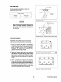
Cylinder Head Inspection and Repair
Check cylinder head surface for warpage between
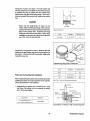
bolt holes: within O.05mm
Check guide for ware and damage.
Check for cracks, damage,
water leak and remove oil, sludge,
sealant deposit, carbon deposit.
Check for valve contact,
wear, damage, and sink of seat face.
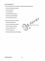
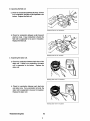
Valve Guide Replacement
(\625)
(\612)
If a valve guide is found defective. replace it.
(\66.6
i
1. Remove the valve guide by pressing at its upper
end and pull it out to the valve seat side.
I
2. Install the valve guide by press fitting the guide
from the upper side ofthe cylinder head to a height
of 14 ± 0.5 mm from the valve spring seat face.
'--
I
Press·fitting Valve Guide
Westerbeke Engines
28
I
I
I
I
-
(
Valve Seat Repair
Valve sinkage
If a valve seat is found defective, reface it or
replace the cylinder head.
Sinkage of valve
Interface
and wear
Standard
Service limit
0.5 mm
1.5 mm
Checking Valve Sinkage
CAUTION
When checking valve sinkage, the valve guide
must be in normal condition. Resurface the
valve seat so that it contacts the mid-portion of
the valve face.
Resurfacing Valve Seat
(Common to intake and exhaust valves)
Valve Seat Installation
Installation of the cylinder head is in the reverse
order of removal. Pay attention to the following.
1. Renew the cylinder head gasket. No application
of sealant is necessary. On the upper front of the
gasket is engine model to which that gasket is
applicable. Be careful not to confuse it with a
gasket for another engine model.
2. Tighten the cylinder head bolts in the numerical
order shown in the figure at right, going through
that order two or three times. Tighten each bolt a
little at a time until all are tightened to the specified
torque.
Sequence for Tightening Cylinder Head Bolts
3. When connecting the injector line assembly,
loosen the pipe clamp. When tightening the nut
at each end of the pipe, grip the nozzle holder or
delivery valve holder with a wrench to prevent it
from being turned together with the nut. Also, take
care not to allow dust to enter the fuel line.
Sequence for Tightening Cylinder Head Bolts
29
Westerbeke Engines
VALVES AND VALVE SPRINGS
~=---':~'
~--(2)
..----@
VALVE SYSTEM COMPONENT PARTS
1. Valve stem cap.
2. Retainer lock.
3. Valve spring retainer.
Westerbeke Engines
4. Valve stem seal.
5. Valve spring.
6. Valve.
30
Valve Removal
1. Dismount the cylinder head assembly.
2. Depress the valve retainer (to compress the valve spring) and remove the retainer lock.
3. Remove the valve.
Valve Inspection and Repair
If any parts are found defective, repair or replace them.
Q------
Wear and damage
(Without for agricultural)
~~
@
Dents and wear
I - - - - - R i d g e and damage
Margin
Inspection of Valve and Valve Spring
Valve fatigue and damage
Inspection item
Standard
Service limit
Free length (Dim)
40.5
-I
Load (kg/ mm)
5.94/35.5
-15%
Squareness
2'
3'
Margin (mm)
1.0
0.5
valve spring te5ter
31
Westerbeke Engines
1. If the valve face is found worn down, resurface it
with a valve refacer. If the margin of the resurfaced valve exceeds the service limit, replace the
valve.
I---
f--
2. If the valve stem end has been indented by wear,
flatten it with an oil stone.
./
"
, - -- /~------"'..."
45" \ / /
~Margin
t•
/
I
Inspecting Valve
Valve and Valve Spring Installation
1. Install the valves and valve springs, referring to notes shown in the figure below.
2. Mount the cylinder head assembly.
3. Adjust the valve clearances.
CAUTION
Be careful not to damage the spring and stem seal by excessively compressing the spring
when installing the valve spring.
With retainer
depressed to compress
spring. install
retainer lock.
Press this surface
Driving in
stem seal
Installing spring
Installation of Valve Spring
Westerbeke Engines
32
Installing spring retainer
VALVE CLEARANCE ADJUSTMENT
Valve Clearance Adjustment
Cylinder head bolts lIl.USt. be retightened before adjusting the valve clearance. When retightening the cylinder
head bolts, draw out coolant, loosen the bolts slightly,
and then retighten the bolts to the specified torque in the
numerical order illustrated at right.
Tightening torque:
M10 bolt
54.2 - 61.5 Ib-ft
(7.5 - 8.5 kg-m)
M8 bolt
10.8 - 15.9 Ib-ft
(2.0 - 3.0 kg-m)
0
o
2
4
0
1
Cylinder Head Bolt Tightening Sequence
208
Cylinder Head Bolt Tightening Sequence
308
The rocker assembly (the rocker arms, shaft, and stays)
is to be kept removed when the cylinder head bolts are
retightened.
Rocker stay tightening torque: M8 bolt 10.8 - 15.9 Ib-ft
(1.5 - 2.2 kg-m)
1. Set the cylinder to be adjusted to the top dead center
of the compression stroke.
Valve clearance: 0.0098 in. (0.25 mm) (cold) for
both intake and exhaust valves.
ADJUST EXH.\USl' V.UVES TO 0.012 INCH&'!
(11.:111 ~ .. )
2. The top dead center of the compression stroke can
be obtained by aligning the T.O.C. (Top Oead Center)
mark (notch) on the crankshaft pulley with the mark
on the gear case.
ADJUST INTAKE VALVES TO 0.010 I:SCHES
(0.2~ MM)
3. First align the T.O.C. mark for the No. 1 cylinder.
Confirm that the valves do not move up and down
when the crankshaft is turned about 20° in the normal
direction of rotation and in the reverse direction.
4. When setting the top dead center for the 3 cylinder
engine, perform as follows:
a. Two Cylinder Engine From T.O.C. for the NO.1
cylinder, turn the crankshaft 180° clockwise and the
NO.2 cylinder is set to T.O.C.
b. Three Cylinder Engine From the T.O.C. for the No.
1 cylinder, turn the crankshaft 240° clockwise to set
the No.3 cylinder T.O.C. Further, turn the
crankshaft 240° clockwise, and the No. 2 cylinder
is set to T.O.C.
Injection Timing Mark
33
Westerbeke Engines
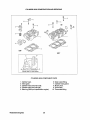
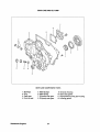
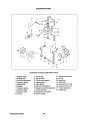
GEAR CASE AND OIL PUMP
(Ii)
'!})
GEAR CASE COMPONENT PARTS
1.
2.
3.
4.
Bushings.
Plug.
Gear case.
Front oil seal.
Westerbeke Engines
5.
6.
7.
8.
Relief plunger.
Relief spring.
Oil pump inner gear.
Oil pump outer gear.
34
9. Oil pump housing.
10. Gear case gasket.
11. High-pressure pump gear housing.
12. Housing gasket.
Gear Case and Oil Pump Removal and Inspection
1. Remove the crankshaft pulley.
2. Remove the fan and fan belt.
3. Remove the tie-rod cover from the side face of the injection pump.
4. Remove the tie rod and tie rod spring. Be careful not to let the spring fall into the case.
5. Remove the governor cover assembly.
6. Remove the water pump assembly.
7. Remove the alternator.
8. Remove the pump housing.
9. Remove the gear case assembly.
Check the removed parts. If any parts are found defective, repair or replace them.
Cracks and damage
Wear and damage
0~~\
@
© r[J)
S,rio,
/
[(({W f7lr\
f",~
I
Wear, damage, and clearance
~
Smooth movement
@
I
Thoroughly clean oil line.
Seal surface interference
Inspection of Gear Case and Oil Pump
35
Westerbeke Engines
Front Oil Seal Replacement
1. Remove the front oil seal.
2. Press-fit the new front oil seal.
CAUTION
Apply a thin coat of engine oil to the circumference and lip of the oil seal.
Governor Shaft Bushings' Replacement
1. Remove the expansion plug and draw the bushings out.
2. Press-fit the new bushings into positions shown in
the figure at right.
To be flush with
this plane
To be in contact
with bottom
Press· fitting Governor Shaft Bushing
Governor System Inspection
Check springs
for fatigue.
Check the governor system parts. If any parts are
found defective, repair or replace them.
Check shaft
for flaws.
Check sliding sleeve
joint for wear and damage.
Check weight for wear and damage.
Westerbeke Engines
36
Governor Levers' Disassembly and Reassembly
Expansion plug
1. Removal of the shaft.
Grooved pin
Projection
approx.2mm
a. Remove the expansion plug, taking care not to
scratch the gear case.
b. Pull out the grooved pin.
Section A-A
2. Installation of the shaft.
Gear case
a. Install the shaft in the reverse order of removal.
Installing Governor Shaft
b. After installing the shaft, press-fit the expansion plug
into the shaft hole in the gear case.
Gear Case Installation
Tightening torque
O.8-1.0kg.m
~
Tightening torque:
4-5kg.m
Taper plug tightening
torque: 1.5-2.2kg.m
Sealant: HERMESEA
H1 or THREE-BOND 1344
Gear Case Assembly
37
Westerbeke Engines
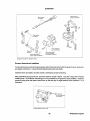
TIMING GEARS
"'4
Cj)
TIMING GEAR COMPONENT PARTS
1. Crankshaft gear.
2. Idle gear.
Westerbeke Engines
3. Camshaft gear.
4. Injection pump camshaft gear.
38
Timing Gears' Removal
1. Pry the snap ring out and remove the idle gear.
2. Remove the valve camshaft and injection pump camshaft on which the respective gears are press-fitted.
Remove the gears from the shafts.
3. Remove the crankshaft. Remove the gear from the
crankshaft.
Timing Gears' Inspection
Check the removed gears. If any gear is found defective,
replace it.
Injection pump
camshaft gear
-r....-,,,.: _ /
Check tooth faces
and end surfaces
for wear and damage.
Idle gear bushing
Description
Standard value
Service limit
Clearance between bush·
ing and shaft
0.03 - 0.07
0.2
Backlash between gears in mesh
Description
Standard value
Service limit
0.01 - 0.14
0.3
Crankshaft-Idle
Idle-Camshaft
Idle-Fuel pump Gear
/
Crankshaft gear
Valve camshaft gear
Inspecting Timing Gears
39
Westerbeke Engines
Timing Gears' Installation
1. Press-fit the crankshaft gear onto the shaft.
2. Press-fit the valve camshaft gear and injection
pump camshaft gear onto the respective shafts.
3. Install the gears in the following sequence.
a. Turn the crankshaft to set the No. 1 cylinder to
top dead center on compression stroke.
Idler Gear
(Note timing marks1&2)
b. Install the valve camshaft and injection pump
camshaft.
c. Install the idle gear so that timing marks on it are
in alignment with marks on the other gears.
d. Confirm that timing gears are in alignment with
each other.
Westerbeke Engines
40
CAMSHAFTS (Valve and Pump)
@
@
@
I
~~
rID
@
(1)
CAMSHAFT COMPONENT PARTS
8. Tappet.
9. Push rod.
10. camshaft (injection pump).
11. camshaft gear.
12. Ball bearing (rear).
13. Snap ring.
1. Camshaft (valve).
2. Camshaft gear.
3. Ball bearing.
4. Woodruff key.
5. Sunk key.
6. Camshaft stopper.
41
Westerbeke Engines
Valve Camshaft Removal
1. When it is necessary to remove only the valve camshaft, use the following procedure.
a. Dismount the cylinder head assembly.
b. Pull out the push rods.
c. Pull out the tappets.
d. Remove the gear case assembly.
e. Remove the camshaft stopper bolt.
f. Draw the camshaft assembly out.
2. Removal of the injection pump camshaft.
a. Disconnect the injector lines.
b. Remove the injection pump assembly.
c. Remove the gear case assembly.
d. Remove the shaft rear cover.
e. Remove the stopper bolt.
f. Remove the shaft from the front of the engine.
Westerbeke Engines
42
Camshafts' Inspection
Cam lobe-Wear
and damage
Bend---
End
face-Wear
and damage
Journal bearing-Wear
and damage
Each ball
bearing-Wear
and noise
Cam contact
surface-Wear
and damage
Cam lobe-Wear
and damage
Oldham's coupling-Wear
Inspection of Camshafts
Major diameter of injection pump cam
Major diameter of valve cam
Standard value
30
Standard value
27.37
Service limit
-0.7
Service limit
-1.0
43
Westerbeke Engines
Camshafts' Installation
When installing the camshafts, give care to the following.
1. Coat the bearings and cam lobes with oil.
2. Install the camshafts in the reverse order of
removal.
3. Position the timing marks on the gears in alignment
with the marks on the idler gear.
4. After installation, check and adjust fuel injection
timing and valve clearances.
Westerbeke Engines
Timing Gears in Alignment with Each Other
44
PISTON AND CONNECTING ROD
Os-=-- :
---(J)
€3
1_ ' ! l 1
(~)~
€!---I
~"
(8)--IQ'
PISTON AND CONNECTING ROD COMPONENT PARTS
1. Piston ring No.1.
2. Piston ring No.2.
3. Oil ring.
4. Piston.
5. Piston pin.
6. Connecting rod.
7. Connecting rod bearing.
45
8. Connecting rod cap.
9. Connecting rod bolt.
10. Connecting rod nut.
Westerbeke Engines
Piston and Connecting Rod Removal
1. Remove the cylinder head assembly.
2. Remove the oil pan.
3. Remove the oil screen.
4. Chalk the cylinder number on the side face of the big end of each connecting rod to prevent confusion
of connecting rods.
5. Remove the connecting rod cap from each piston
and rod assembly and draw the assembly upward
from the cylinder. Take care not to allow the connecting rod to scratch the crankshaft pin and
cylinder. Keep the removed parts (connecting rod,
rod cap, piston etc.) classified by cylinders.
6. Remove the rings from each piston with the piston
ring pliers.
7. Using the piston setting tool, pull out the piston pin
from each piston.
Pressing
FRONT
mark (arrow)
Piston
Removing Piston Pin
Piston and Connecting Rod Inspection
Inspect the removed parts. If any parts are found defective, replace or repair them.
Damage, wear, _ _ {
and ring gap
• Bend and twist
- - - • Big end play
Standard: 0.1 -O.35mm
08----::
8
~
~~
• Wear, seIzure, and streaks
• Clearance between piston and cylinder
tf~. ~
Standard:O.07-0.115mm
----- ~
• Wear of p,ston ring grooves
~
}
$
Damage and wear
-------V
-
• Contact and seizure
• Flaking and fusion
• Oil clearance
Standard: O.022-0.052mm
® ___- - Damage
Inspection of Piston and Connecting Rod
Westerbeke Engines
46
Inspection of piston ring gaps. Put each piston ring
into the cylinder bore and push the ring with the piston
to position the ring on square with the cylinder wall.
Measure the ring gap with a feeler gauge. If the measurement exceeds the service limit, replace that piston
ring.
Piston
o
Cylinder
CAUTION
Ring
When only the replacement of rings is to be
made, without reboring (honing) of the cylinder,
position the ring to be measured at the least worn
place of the cylinder skirt. Install the new rings
having the same size as the piston. Piston rings
available for servicing are sized into three classes: STD, 0.25 OS, and 0.50 OS.
Ring gaps
Measuring Ring Gap
Ring
Standard
Service limit
All rings
0.15-0.40
1.5
Inspection of ring groove in piston. Measure the side
clearance for each piston ring set in the ring groove in
the piston. If the service limit is exceeded, replace the
ring with a new one.
Measuring Ring Side Clearance
Piston and Connecting Rod Installation
When reassembling the piston and connecting rod and
installing the piston and rod assemblies in the cylinder
block, pay attention to the following.
Ring
Standard
Service limit
No. I
-
0.3
No.2
0.05-0.09
0.2
Oil
0.03-0.07
0.2
Note : No. I ring is of the semi·key stone type.
Pressing
1. Reassemble the piston and connecting rod, using
the Piston Pin Setting Tool, by pressing the piston
pin in to the set position.
FRONT
mark (arrow)
Description
Pin press·fitting force
(at a normal temperature)
Piston
Standard
1000±500kg
Installation of Piston and Connecting Rod
47
Westerbeke Engines
Pressing
Push rod
Connecting rod
FRONT mark (arrow)
', .....~~-- Tool body
2. Installation of piston rings.
FRONT mark - - -.....
Ring set positions:
No.1 ring.
No.2 ring.
oil ring
d
~
"r
mark and
OS size mark
"r mark and
OS size mark
Rod front --.------~
mark
OS size
identification
paint
Align notches accurately with
each other.
Color of discrimination STO =Without color
O.25=White
O.50=Blue
Tightening torque: ____{O"\
3.2-3.5kg.m
\01
Installation of Piston Rings and Connecting Rod Cap
Westerbeke Engines
48
3. Set the piston ring gaps to the proper positions as
shown in the figure at right. Coat the rings and
cylinder wall with oil.
Ol'ri"if
~
~
Front ~
~
No.2 ring
No.1 ring gap
gap~
,J!."
0' 0011
expander of oil
ring
Proper Arrangement of Ring Gaps
4. Using a piston ring compressor to compress the rings into the grooves, push the piston and rod assembly
down into the cylinder. Be careful not to break the rings by excessively knocking the head of the piston.
Note that the front marks on the piston and connecting rod are toward the engine front.
5. Coat the bearing surface of the connecting rod caps
with engine oil. Fit each cap to the connecting rod
using match marks put before removal as a guide.
In the case of a new rod which does not have a mark,
position the notches (provided for preventing the
bearing from rotating) on the same side.
Connecting
Rod
I
I
:
:
~
I
I
I
~
I
I
I
I
~cap
®
49
Westerbeke Engines
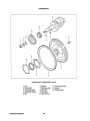
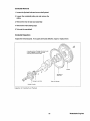
CRANKSHAFT
®
CRANKSHAFT COMPONENT PARTS
1. Key.
2. Crankshaft.
3. Crankshaft gear.
4. Crankshaft pulley.
5. Nut.
Westerbeke Engines
11. Rear oil seal case.
6. Washer.
7. Spring washer. 12. Gasket.
8. Flywheel.
13. Flywheel bolt.
9. Ring gear.
10. Rear oil seal.
50
Crankshaft Removal
1. Loosen the flywheel bolts and remove the flywheel.
2. Loosen the crankshaft pulley nut and remove the
pulley.
3. Remove the rear oil seal case assembly.
4. Remove the main bearing caps.
5. Take out the crankshaft.
Crankshaft Inspection
Inspect the removed parts. If any parts are found defective, repair or replace them.
• Journals and pins- Damage and uneven wear
• Cracks. clogging of oil hole, and bend
• Wear of journal contact surface
Wobble
Damaged to
tooth face
Wear and damage
Inspection of Crankshaft and Flywheel
51
Westerbeke Engines
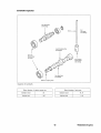
Checking the crankshaft for wear. To check the
crankpins and main journals for tapering wear and
out-of-round wear, the diameter of each crankpin or
main journal should be measured at two places along
the crankpin or main journal, in two directions "A" and
"B" each place, as shown in the figure at right. If
necessary, regrind the crankpins and main journals to
the next under size. If any crankpin or main journal
has been worn out beyond the service limit, replace
the crankshaft.
Checking Crankshaft for Wear
Diameter of crankpin and main journal
Description
Main
dia.
journal
Crankpin dia.
(mm)
Under·size diameters
Description
(mm)
Main journal
Crankpin
Standard
Service limit
43
-0.70
0.25 US
42.715""'42.730 39. 715""'39. 730
40
-0.70
0.50 US
42.465""'42.480 39.465""'39.480
Inspection of the crankshaft oil clearance.
Oil
clearance is calculated by subtracting the diameter of
main journal or crankpin from the inside diameter of
the main bearing or rod bearing. To check the main
bearings and rod bearings for tapering wear and outof-round wear, the inside diameter of each main bearing or rod bearing should be measured, after its
bearing cap is fastened to the specified torque, at two
places along the bearing, and in two directions "A" and
"B", each place as shown in the figure at right. If
necessary, replace the worn bearing with a new one.
If the oil clearance still exceeds the service limit,
regrind the crankshaft to the next under size and
replace the bearing with one of the corresponding
under sizes.
2
Measuring Main Bearing 1.0.
CAUTION
A crankshaft which has been sized cannot be reground to any under size.
Tightening torque
(kgm)
Oil clearance
(mm)
Description
Standard
Description
Main bearing cap bolt
5.0""'5.5
Main bearing
0.10
Rod bearing cap nut
3.2""'3.5
Rod bearing
O. 15
Westerbeke Engines
52
Service limit
Crankshaft Rear Oil Seal Replacement
1. Pry the oil seal out with a screwdriver.
2. Drive in a new oil seal to the oil seal case.
When installing the crankshaft, pay attention to the notes given in the figure below.
Cap tightening
torque: 5.0- 5.5kg.m
Thrust bearing only
for No.2 cap
J
Side seals coated
with sealant
, 7-'ONO "'"
Direction of
installation of cap
-\ 9
.-J~ Round end down
Front
Make cap flush with
cylinder block end face
(common to front and
rear end faces)
Crankshaft end
play: 0.05-0.175
Installation of Crankshaft
53
Westerbeke Engines
CYLINDER BLOCK
CYUNDER BLOCK COMPONENT PARTS
1. Cylinder block.
2. Front plate.
3. Bearing cap.
4. Cover.
Westerbeke Engines
5. Main bearing.
6. Starter bracket.
7. Rear oil seal.
8. Oil seal case.
54
9. Idler gear shaft.
10. Oil filter shaft.
11. Oil level gauge guide.
Cylinder Block Inspection
Inspect the cylinder block. If it is found defective, repair or replace the block.
Cylinder Bore (mm):
Mgdel
20B
30B
Standard
76 + 0.03 -0.0
76 + 0.03 -0.0
A pprox.10mm
from upper end
Front
Wear Umit Before Rebore:
+ 0.02 mm
-
Lower
'--
~
~\J7
Center
,
Direction of
measuing
Measuring position
Cylinder Bore Measuring Positions
Cylinder Reboring
When reboring a cylinder, use the following procedure.
1. Select a piston size: 0.25 as or 0.50 as.
2. Measure the piston diameter.
3. Reboring finish dimension = [piston 00]
[clearance] - [honing allowance (0.2 mm)]
+
I~
0
l
55 mm
Measure
diameter
here ----L.-~r
Clearance (between piston and cylinder)
Standard: 0.071 - 0.084 mm (A-D)
Measuring Piston Diameter
CAUTION
When it is necessary for a cylinder to be rebored to the next over size, the remainders must
also be rebored to the same over size.
55
Westerbeke Engines
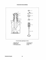
FUEL INJECTION PUMP
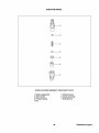
INJECTION PUMP COMPONENT PARTS
1. Union collar.
8. Delivery valve.
9. Gasket.
3. Delivery valve holder. 10. Seat valve.
4. Valve spring.
11. Plunger barrel.
5. Holder stopper.
12. Sleeve.
6. Housing.
13. Upper seat.
7. O-ring.
14. Plunger spring.
Westerbeke Engines
56
15. Plunger.
16. Lower seat.
17. Adjusting shim.
18. Tappet roller.
19. Pin.
20. Control rack.
21. Stop wire bracket.
Injection Pump Inspection while on the Engine
Inspection
Inspection procedure
Never attempt to disassemble the pump unless it is
necessary. If the pump is assumed defective, it is
recommended to replace the pump assembly.
Idling speed
Measure engine speed.
Criterial
900+ sgrpm
I) Quickly accelerate
Exhaust smoke color
No remarkably black·
engine without load.
smoke exhaust permitted.
2) Apply load to engine
Injection Pump Removal
Fuel cut ·off
Turn ignition switch to OFF
A solenoid acting
solenoid
from ON.
sound.
1. Disconnect the fuel injection pipes.
2. Remove the tie-rod clip cover.
'~fn1:lction
---IJ
3. Remove the tie-rod clip and tie-rod.
Pipes
I
I I
M,~,e
Injection Pump Disassembly
,~'~
1. Remove the stopper plate.
2. Unscrew the delivery holder. Take out the delivery
valve and valve spring.
3. Remove the tappet roller and stopper pin.
4. Remove the tappet, plunger spring, etc.
CAUTION
When replacing the plunger barrel, delivery
valve, etc., do not loosen the adjusting screw and
plate for each cylinder. When those parts have
been replaced, it is necessary to measure fuel
injection quantity by utilizing a pump tester and
cam box. All parts removed from the pump
should be kept classified by cylinders and immersed in clean fuel.
0 - O-ring-Cracks
~
and deterioration
©
fj-Control rack-movement
(Catching)
~t~11"-
~
Injection Pump Inspection
Wear and
scratch
Plunger-Interference
wear, scratch,
rust, seizure
I8J
I®
o
e-
, ri?Jc:::::,
Interference,
wear
Inspection of Injection Pump
57
Westerbeke Engines
Injection Pump Assembly
1. Insert the plunger barrel into the housing.
2. Install the delivery valve and valve spring. Temporarily tighten the holder.
3. Insert the control rack.
4. Insert the control pinion. Align the matchmark on the rack with that on the pinion.
5. Install the spring upper seat.
6. Insert the plunger spring.
7. Fit the lower seat to the plunger. Insert the plunger into the barrel side.
8. Depress the tappet roller assembly and install the stopper pin.
9. Tighten the delivery holder.
Tightening torque: 3.5 - 3.9 kgm
Injection Pump Installation
Install the injection pump assembly in the reverse order
of removal.
Stamp
CAUTION
When installing the plunger barrel, engage the
dowel pin on the housing side with the groove in
the barrel. Position the plunger so that the part
number stamp on its flange faces the direction
opposite to the rack side. (Engage the feed hole
with the plunger lead.) After installation, check
for proper injection timing.
Westerbeke Engines
58
Rack side
Direction of Installation of Plunger
INJECTION NOZZLE
@:_--
I
::g
<9
@
@
@
NOZZLE HOLDER ASSEMBLY COMPONENT PARTS
1. Body subassembly.
2. Shim washer.
3. Pressure spring.
4. Pin.
5. Distance piece.
6. Nozzle assembly.
7. Retaining nut.
59
Westerbeke Engines
Injection Nozzle Removal
1. Disconnect the injection pipe and fuel return pipe.
2. Remove the injection nozzle assembly from the cylinder head.
CAUTION
Attach an identification number tag to the removed injection nozzle. Plug the openings from
which the pipes are disconnected and the nozzle is removed to prevent intrusion of dust,
water, and other foreign particles into the pipes and combustion chamber.
Injection Nozzle Disassembly
If the removed nozzle assembly is assumed defective, disassemble the assembly and repair or replace the
faulty parts.
1. Grip the nozzle holder body in a vise. Loosen the retaining nut. Never vise the retaining nut to prevent
deformation.
2. Take out the shim washer, pressure spring, distance piece, and nozzle assembly.
CAUTION
Scrape off carbon deposits with a wooden spatula. Keep the removed parts immersed in
washing oil (kerosene). Take special care not to scratch the needle valve in the nozzle
assembly.
Injection Nozzle Inspection
Inspect the removed parts. If any part is found defective, replace it.
Injection Nozzle Assembly
~
. Fatigue and
break
1. Insert the nozzle assembly into the retaining nut so
that the nozzle is perfectly seated in the nut.
!gl/
2. Place the distance piece, retaining pin, pressure
spring, and shim washer on the nozzle assembly.
©
@
3. Tighten the nozzle holder body fully by hand.
Poor contact
~
~
4. Grip the nozzle holder in a vise. Tighten the retaining nut to the specified torque.
9
Tightening torque: 3.5 - 4.0 kgm
Inspecting Nozzle
Westerbeke Engines
60
~T
Deformation
and break
While immersed
in kerosene.
check for smooth
sliding.
Injection Nozzle Adjustment
Adjust injection start pressure by increasing or
decreasing the thickness of the shim washer to be
inserted. Varying shim thickness by 0.1 mm causes
injection start pressure to change 10 kg/cm.
Tightening torque:
2.5-3.0kg.m
Tightening torque:
3.5-4.0kg.m
10 kinds of shims available from 1.25 mm to 1.7 mm in
thickness, 0.05 mm step.
Injection start pressure
Return pipe
Standard
Allowable limit
Assembling the Nozzle
130 kg/ an' or less
Injection Nozzle Installation
1. Clean the nozzle holder fitting surface of the cylinder head. Install the nozzle holder with a gasket
interposed.
Tightening torque: 5.0 - 6.0 kgm
2. Connect the fuel return pipe and injection pipe.
Tightening torque:
Injection pipe
Fuel return pipe
2.5 -3.5 kgm
2.5 -3.0 kgm
61
Westerbeke Engines
GOVERNOR SYSTEM
I---@
®
GOVERNOR SYSTEM COMPONENT PARTS
1. Sealing metal.
2. Sealing wire.
3. Low and high speed.
4. Governor spring.
5. Sliding shaft.
6. Stopper
7. Governor spring.
8. Governor shaft.
9. Governor lever.
10. Tie-rod.
Westerbeke Engines
11. Tie-rod clip.
12. Tie-rod cover.
13. Tie-rod cover gasket.
14. Tension lever
15. Start spring.
16. Governor spring lever.
17. Speed control lever assembly.
18. Cover assembly.
19. Governor cover gasket.
20. Return spring.
62
21. Stop lever assembly.
22. O-ring.
23. Snap ring.
24. Stop lever.
25. Grooved pin (3 x 20).
26. Grooved pin (3 x 14).
27. Torque spring test.
28. Sealing cap.
Torque Spring Set Installation
Torque spring set
Install and adjust the torque spring set using the following procedure:
1. Set the speed control lever to the high idling speed
position by adjusting the high speed set bolt.
Turn in this torque spring
set until engine speed
drops about 50rpm from
high-idling speed.
2. Turn in the torque spring set until engine speed drops
about 50 rpm from high idling speed.
3. From this position, turn back the torque spring set
by the specified number of turns (N). Lock the
torque spring set at that position with the special nut.
Adjust to specified
number of loosening
turns -N"
Sealing cap
(Stake after setting)
Number of loosening
4. Install the torque spring set sealing cap and stake
the cap to prevent loosening.
~
20B Two & 30B Three
Number of loosening
turns (N)
2.2
Torque spring set
Torque Spring Set Assembly
2. Spring 1. Spring
When the torque spring set has been disassembled or
its component parts have been replaced, reassemble
and adjust the torque spring set using the following
procedure:
. tr
Projection
identification
mark
1. Assemble the torque spring set as shown in the
figure. Using the adjusting screw (5), adjust the
projection (8) of the torque spring stopper (1) from
the spring case (2) to get the specified projection.
6. Torque spring
Assembling torque spring set
2. To measure the projection (8), keep the torque
spring set in vertical position as illustrated. Put the
dial gauge probe against the spring stopper (1) at
the center of its end face using a small dial gauge
(having the sensitive probe which does not compress the torque spring when pushed against the
spring stopper end).
A : Height of spring stopper
B : Height of case
Measuring spring stopper projection (0)
63
Westerbeke Engines
3. Leaving the dial gauge set condition unvaried, depress the spring stopper (1) and slide the torque spring
set support spring case (2). Read the deflection of dial gauge which corresponds to the projection of the
spring stopper from the spring case. (Measurement should be made two or three times repeatedly to
make sure of accurate measure.) For the models which do not require any torque spring action, set the
projection (8) to a value in the range of 0 to -0.4.
4. After adjustment, tighten nut (4) to a torque of 0.8 to 1.2 kgm.
5. Check to see that the spring stopper (1) can be depressed smoothly and that the end face of the stopper
(1) can become flush with the end face of the spring case (2).
6. For the purpose of identification of projection (8), apply paint of the color specified to the surface shown
in the figure at the right of paragraph (1).
MQd.eL
206 Two & 306 Three
projection 8 mm
o '" -0.4
Identification color
Red
Replace the gear case and inspect the governor. When removing the gear case, be sure to remove the
tie-rod cover by the side of the fuel pump and disconnect the tie-rod from the rack. If any parts are found
defective, replace them.
CAUTION
If the governor is assumed to be malfunctioning, check the bearing on the gear case side,
too.
Westerbeke Engines
64
GOVERNOR
~GJ
Check springs
for fatigue.
~~\d)./
Check levers for
smooth movements.
7
~\,i)
Check springs
for fatigue.
~~
Check shaft
for flaws.
Check sliding sleeve
joint for wear and damage.
Check weight for
wear and damage.
Check sliding sleeve
for wear, damage
and smooth movement.
Inspection Governor System Parts
Governor Removal and Installation
To remove the levers, pull out the grooved pins which have been driven into the governor lever, stop lever,
and speed control lever. Loosen the bolts fastening the levers and shafts.
Install the levers and shafts, one after another, checking for proper functioning.
After press-fitting each grooved pin, check the shaft for smooth rotation. Coat the O-rings with oil before
installing them. No deflection exceeding 20 mm is permitted for the governor spring installed. Install the
governor spring lever and speed control lever so that the play of angle between levers (standard: 5°) is
minimized.
5' (Standard)
No play exceeding
5' permitted
Instaling Speed Control Lever
65
Westerbeke Engines
GLOW PLUG
Glow Plug Inspection
Check for conduction between the glow plug terminal and body. Ifthe plug is not conductive at all or shows
a large resistance, replace the plug.
Glow plug tightening torque: 1.5 - 2.0 kgm.
Checking Glow Plug
Westerbeke Engines
66
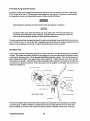
COOLING SYSTEM
Illustrated below is a typical Westerbeke engine cooling system. Both fresh water and raw waterflow through
their independent cooling circuits. Refer to your generator's Parts List for part numbers and part descriptions
if you need to order cooling system parts for your engine.
INJECTED
E~- _ _ _ _ _ PRESSURE
CAP
EXHAUST MANIFOLD
WATER
~'r---=~-_ TEMPERATURE
.~~"'1'
SWITCH
{7'
INCOMING
RAW WATER
FRESH WATER ~
FRESH WATER DRAIN
RAW WATER . . .
RAW WATER DRAIN
Typical Cooling System
67
Westerbeke Engines
Fresh Water Pump Drive BeH Tension
Generator models come equipped with belt guards that cover over the belt(s) on the front of the engine.
("Out of sight-out of mind." The belt guard is not installed for that purpose.) Operators are advised that
the inspection, service, and maintenance spoken of below should be followed.
IWARNINGI
Never attempt to adjust the drive belt's tension while the engine is in operation.
CAUTION
Excessive water pump drive belt tension can cause rapid wear of the belt and reduce the
service life of the fresh water pump's bearings. Excessive slack or the presence of oil on the
belt can cause belt slipping, resulting in high operating temperatures.
The water pump drive belt is properly adjusted if the belt can be deflected no less than 3/8 inch and no more
than 1/2 inch (10 mm, 12 mm) as the belt is depressed with the thumb at the midpoint between the two
pulleys on the longest span of the belt. A spare drive belt should be carried on board.
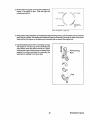
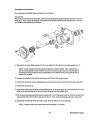
Raw Water Pump
The raw water pump is a self-priming, gear-driven, rotary pump with a non-ferrous housing and a neoprene
impeller. The impeller has flexible vanes which wipe against a curved cam plate within the impeller housing,
producing the pumping action. On no account should this pump be run dry. There should always be a
spare impeller and impeller cover gasket aboard (an impeller kit). Impeller failures occur when lubricant
(raw water) is not present. Such failures are not warrantable and the operator's are cautioned to make sure
raw water flow is present at start-up. Know your pump, know its location on the engine and know how to
change the impeller in it.
CURVED CAM PLATE
RAW WATER PUMP
Remove the impeller with the aid of two small screwdrivers, as illustrated, and carefully pry the impeller
out of the pump. Install the impeller by positioning the hub pin to align with the slot in the drive shaft.
Move the blades to conform to the curved cam plate and push the impeller into the pump's housing.
Westerbeke Engines
68
Raw Water Pump Overhaul
Raw water pump #033636 repair instructions are as follows:
Disassembly
The pump, as removed from the engine, will have hose attachment nipples threaded into the its inlet and
outlet port. They may be left in place or removed if they interfere with the pump disassembly. Note the
port location and positioning if removed.
a. Remove the six cover plate screws (ref 13), cover plate (ref 12) and the cover plate gasket (ref 11).
NOTE: Screw material should be stainless steel part number 034463. Also, replacement of
the cover plate gasket is recommended; however, if you are going to reuse it, keep the gasket
submerged in water until the pump is reassembled. If it's allowed to dry, the gasket will shrink
and not be reusable
b. Remove the impeller (ref 9) with its drive screw (ref 10) from the pump housing.
c. Remove the screw (ref 4) and sealing washer (ref 5) and draw the cam (ref 6) from the pump housing.
d. Remove the circlip (ref 3).
e. Support the pump housing, at the mounting flange end, on an arbor press and, with a drift, press out the
shaft (ref 8) and bearings (ref 2) from the pump housing from the impeller end.
f. With the pump housing supported, push the seals (ref 7) out of the pump housing. Push the impeller side
seal out that side and then lift the spacer (ref 14) out. Then, push the bearing side seal out that side.
g. Supporting the bearings inner face (ref 2), push the shaft (ref 8) out of the bearings.
NOTE: Inspect all parts and replace those showing wear or corrosion.
69
Westerbeke Engines
Assembly
a. Install the seals (ref 7) and spacer (ref 14) in the pump housing. Push the impeller side seal into the
housing. Rotate the pump and install the spacer (ref 14) against the seal face. Push the bearing side
seal into the housing from the bearing side.
NOTE: The seal's flat surfaces, having printing and numbers, face towards each other.
b. Install shaft (ref 8) into bearings. Support bearings (ref 2) at their center race. Push the shaft into the
bearings, pushing at the impeller drive slot end using the base of the drive slot. Push the shaft through
both of the bearings, flush against each other so the flat sided end of the shaft extends beyond the second
bearing center race 15 mm (19/32 in.) ±.5 mm (1132 in.).
c. Support the pump housing at the impeller side. Apply a small amount of petroleum jelly to the seal's (ref
7) inner lips and to impeller shaft (ref 8). Carefully, install the shaft rotating it through the seals till the
bearings contact the housing from the bearing end. Use a pushing tool that will push this shaft and
bearing assembly into the pump housing by applying pressure against the outer bearing race. Push the
assembly into the housing until the bearings seat fully in the housing. Install the circlip (ref 3).
d. Position the cam (ref 6) in the housing and secure it in place with the screw (ref 4) and sealing washer
(ref 5).
NOTE: Use a small amount of Permatex #1 on the inner cam surface and screw threads.
Remove any excess from the impeller housing.
e. Apply a light film of silicone or petroleum jelly to the inner surface of the housing for the impeller.
NOTE: Just coat the surface, do not over apply. Install the impeller with the drive screw (ref
9 and 10). Push the assembly into the housing with the drive screw mating in the slot of the
drive shaft.
f. Install the cover gasket (ref 11), cover (ref 12), and secure them with the six cover screws (ref 13).
Westerbeke Engines
70
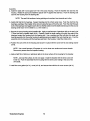
STARTER
(,!l)
I})
lID
.~~
STARTER COMPONENT PARTS
1. Front bracket assembly.
2. Lever assembly.
3. Spring set.
4. Center bracket assembly.
5. Switch assembly.
6. Through bolt.
7. Armature.
8. Rear bearing.
9. Pinion.
10. Pinion shaft assembly.
71
11. Gear.
12. Yoke assembly.
13. Brush holder assembly.
14. Rear bracket.
Westerbeke Engines
Starter Adjustment and Repair
If any abnormality is assumed by the following tests,
adjust the starter or disassemble and repair it.
Push back
Lightly
1. Pinion gap inspection.
a. Interpose a battery (12 V) between the starter
terminallS" and the starter body, and the pinion
will protrude and stop.
O.5-2.0mm
CAUTION
Never apply battery voltage for over 10 seconds
continuously.
Inspecting Pinion Gap
b. Lightly push the pinion back and measure the return stroke (called pinion gap).
c. If the pinion gap is not within the standard range, (0.5 to 2.0 mm), adjust it by increasing or decreasing
the number of packings on the magnetic switch. The gap is decreased as the number of packings
increases.
2. No-load test.
a. Connect the ammeter, voltmeter, and battery to
the starter as illustrated.
b. When the switch is closed, the pinion must
protrude and the starter must run smoothly (at
3000 rpm or more). Ifthe current or starter speed
is out of specification, disassemble the starter
and repair it.
No·load Test
CAUTION
Use thick wires as much as possible and tighten every terminal securely. This is a solenoid
shift type starter which makes a rotating sound larger than that of a direct-drive type starter.
When detecting starter rotation at the pinion tip, take care of protrusion of the pinion.
Westerbeke Engines
72
3. Magnetic switch.
Perform the following tests. If any test result is not
satisfactory, replace the magnetic switch assembly.
a. Disconnect the wire from terminal "M."
b. Attraction test.
Connect a battery to the magnetic switch terminals
Sand M. The pinion must protrude.
Starter
CAUTION
Attraction Test
Do not apply battery current for more than 10
seconds.
c. Holding test.
With a battery connected to the magnetic switch
terminal "S" and to the starter body, manually pull
out the pinion fully. The pinion must remain at that
position even when released from holding by hand.
Starter
CAUTION
Holding Test
Do not apply battery current for more than 10
seconds.
d. Return test.
With a battery connected to the magnetic switch
terminal "M" and to the starter body, manually pull
out the pinion fully. The pinion must return to its
original position when released from holding by
hand.
CAUTION
Starter
Return Test
Do not apply battery current for more than 10
seconds.
73
Westerbeke Engines
Starter Disassembly
1. Disconnect the wire from the magnetic switch terminaI M."
I
2. Loosen the two screws fastening the magnetic switch. Remove the magnetic switch assembly.
3. Remove the two through bolts and two screws fastening the brush holder. Remove the rear bracket.
4. With two brushes brought in a floating state, remove the yoke and brush holder assembly. Then, pull the
armature out.
5. Remove the cover, pry the snap ring out, and remove the washer.
6. Unscrew the bolts and remove the center bracket. At the same time, washers for pinion shaft end play
adjustment will come off.
7. Pull out the reduction gear lever and lever spring from the front bracket.
8. On the pinion side, pry the snap ring out, and pull out the pinion and pinion shaft.
9. At each end of the armature, remove the ball bearing with a bearing puller. It is impossible to replace the
ball bearing press-fitted in the front bracket. If that bearing has worn off, replace the front bracket
assembly.
Westerbeke Engines
74
Starter Inspection
Break and short circuit
Wear and
chipping
Bearing: Play. noise.
and rough rotation
Insulation
Bearing: Play. noise.
and rough rotation
Break and short circuit
Inspect about the following:
Description
Standard
Service limit
Description
Standard
Service limit
Depth of under cut
0.5 mm
0.2 mm
Height of brush
17 mm
6 mm
38.7 mm
-1.0 mm
Spring pressure
3 kg
Commutator O. D.
1. Inspect the magnetic switch for conduction
between terminals S and M and between terminals S
and body. There should be a low resistance found 1 2 ohms. If no resistance is found the circuit is open.
The solenoid should be replaced.
Checking Magnetic Switch
75
Westerbeke Engines
2. Inspecting the armature.
a. Check the armature with a growler tester. If it's
short circuited, replace the armature. Also, check
for insulation between the commutator and its
shaft. If poorly insulated, replace the armature.
b. Measure the commutator 0.0. and the depth of
undercut. Repair or replace it if the service limit
is exceeded. Also, check the commutator outside surface for dirtiness and roughness. If
rough, polish the commutator with fine-grain
sandpaper.
Checking Armature Coil
3. Brush holder inspection.
a. Check the brushes. If worn out beyond the service limit, replace the brushes.
b. Check the brush spring tension. If decreased
beyond the service limit, replace the springs.
c. Check for insulation between the positive brush
holder and holder base. If poorly insulated,
replace the holder assembly. Also, check the
brush holders for proper staking.
4. Field coil inspection.
a. Check for insulation between one end (brush) of
coil and yoke.
b. Check for conduction between both ends
(brushes) of coil.
c. Check the poles and coil for tightness.
Checking Field Coil
Starter Adjustment and Assembly
Reassembly the starter assembly in the reverse order
of disassembly, giving care to the following:
Adjusting
washer
Gear
1. Pinion shaft end play adjustment. Set the end play
(thrust gap) to 0.5 mm or less by inserting an adjusting washer between the center bracket and reduction gear.
O.5mm maximum
a. Fit the pinion shaft, reduction gear washer and
snap ring to the center bracket.
- - f l..- -
Adjusting Pinion Shaft End Play
Westerbeke Engines
76
b. Measure end play by moving the pinion shaft in the axial direction. If the end play exceeds 0.5 mm,
increase the number of adjusting washers inserted.
2. Greasing.
Whenever the starter has been overhauled, apply grease to the following parts:
1. Armature shaft gear and reduction gear.
2. All bearings.
3. Bearing shaft washers and snap rings.
4. Bearing sleeves.
5. Pinion.
6. Sliding portion of lever.
CAUTION
Never smear the starter fitting surface, terminals, brushes, or commutator with grease.
77
Westerbeke Engines
ALTERNATOR
@
I
CD
@
@
@
@
ALTERNATOR COMPONENT PARTS
9. Rectifier assembly.
5. Rear bearing.
1. Pulley.
10. Rear bracket assembly.
2. Front bracket assembly. 6. Stator.
11. Condenser assembly.
7. Terminal set.
3. Front bearing.
8. Regulator assembly.
4. Rotor assembly.
Westerbeke Engines
78
Alternator On-Engine Inspection
1. Erroneous handling can cause damage to the charging circuit and other troubles so avoid the following:
a. Never connect the battery in reverse.
b. Do not use a megger and other high-voltage testers.
c. When recharging the battery, disconnect the battery cable from the alternator.
d. Never disconnect the lead wire from the alternator terminal B while the engine is running.
e. Never ground the alternator terminal B to which battery voltage is always applied.
f. Never short circuit or ground terminal L
g. When using a steam cleaner, be careful not to direct steam directly to the alternator.
2. Checking for regulated Voltage.
a. Interpose an ammeter between the positive terminal of the battery and terminal B or the alternator.
b. Ground the alternator terminal "L" through a
voltmeter.
c. Note that the voltmeter indicates zero volts when
the key switch is in the OFF position. The
voltmeter will indiCate a voltage considerably
lower than battery voltage when the key switch
is in the ON position (while the engine is
stopped).
Ammeter
L
R
Checking for Regulated Voltage
d. Short-circuit the ammeter and start the engine.
e. Read the voltmeter indication (regulated voltage) under the following test conditions: Ammeter
indication is below 5 A; engine speed is at 1800 rpm and 2500 rpm; and lamps are switched off.
Regulated voltage shows a tendency to decrease as alternator temperature increases.
3. Output inspection.
a. Disconnect the grounding cable from the battery.
b. Interpose an ammeter between the battery and alternator terminal "B." Ground the terminal"B" through
a voltmeter.
c. Connect the battery grounding cable.
d. Start the engine.
79
Westerbeke Engines
e. Apply all load Including the lamps.
Ammeter
r-----~+~Ar-----~~
f. Increase engine speed until normal alternator speed
is attained. Read the maximum indication of the
ammeter at 13.5 V of voltmeter indication. Output
current must conform to the specification.
Checking for Output
AHernator Removal
Characteristic
Terminal
voltage (V)
I
Current
(A)
I
1. Disconnect the battery cable.
2. Disconnect the lead wire from terminal "S" on the back
of the alternator.
15A
14
0
No-load I 35A
output 1
14
8
I 1,300
I maximum
I
:
1,300
II maximum
24
1,300
maximum
14
15
maximum
2,500
maximum
35A
14
30
maximum
2,500
maximum
50A
13.5
50
maximum
2,500
maximum
50A
13.5
15A
3. Disconnect the alternator connector.
4. Loosen the alternator brace bolt and support bolt.
Push the alternator toward the engine and remove the
fan belt.
Loaded
output
5. Dismount the alternator.
Alternator Disassembly
1. Remove the three through bolts.
2. Heat the rear bracket around the rear bearing up to
50 - 60° C (with a solder iron) and separate the bracket
from the stator coil.
CAUTION
Pry open the alternator with a screwdriver blade inserted into the clearance between the stator
core and front bracket. Se careful not to insert the blade too deep.
3. Grip the rotor in a vise, remove the pulley nut, and pull out the pulley, fan, and spacer.
4. Pull out the rotor assembly from the front bracket.
Westerbeke Engines
80
Speed
(rpm)
5. Unsolder the stator coil lead wires. Remove the stator assembly.
CAUTION
Never heat the lead wires long to prevent damage to diodes.
6. Disconnect the capacitor from terminal liB.
II
7. Loosen the screws fixing the rectifier and remove the rectifier.
Alternator Inspection
Inspect the disassembled parts, if any part is found defective, replace it.
Deformation
and damage
Break and
short circuit
I
t
~
, I
Wear and roughness
Wear
Break and
short circuit
Wear to limit line
Inspection of Alternator
1. Inspecting the diodes.
a. Connect a circuit tester (ohmmeter) across the lead wire and case of the diode to be tested. The diode
is considered normal if its resistance is large in either direction and small in the reverse direction.
b. If there is equal resistance in both directions, the diode is suspected to be defective. Replace the rectifier
assembly.
c. Check every diode for conduction.
81
Westerbeke Engines
2. Inspecting the field coil.
a. Check for conduction between slip rings. If there
is no conduction, the field coil is suspected to be
broken. Replace the field coil.
Checking Field Coil for Conduction
b. Check for conduction between a slip ring and
shaft (or core). If any conduction is found, the
field coil is suspected to be poor in insulation.
Replace the field coil.
Checking Field Coil for Insulation
3. Inspecting the stator coil.
a. Check for conduction between lead wires of the
stator coil. If there is no conduction, the stator
coil is suspected to be broken. Replace the
stator coil.
Checking Stator Coil for Conduction
b. Check for conduction between each lead wire
and stator core. If any conduction is found, the
stator coil is suspected to be poor in insulation.
Replace the stator coil.
Checking Stator Coil for Insulation
82
Westerbeke Engines
\
AHernator Assembly
Reassemble the alternator assembly in the reverse order of disassembly giving care to the following:
1. The rear bearing has an eccentric groove. Install the snap ring so that its projection fits in with the deepest
part of the groove.
2. When installing a new rear bearing, press-fit the bearing with its groove facing the slip ring side.
3. When press fitting the rear bearing into the rear
bracket, heat the bracket.
CAUTION
Pass a wire through the small hole in the rear
bracket to lift the brushes before installing the
rotor to the rear bracket. Remove the wire after
the rotor is installed.
AHernator Installation
lifting Brushes
Install the alternator in the reverse order of removal.
1. When Installing the support bolts, Insert the
spacer In place using the following procedure:
a. Push In the support bolts to the normal position.
(Leave the nuts removed from the bolts.)
b. Push the alternator backward. Measure the
clearance between the alternator rear bracket
and gear case bracket to determine the number
of spacers to be inserted into the clearance (0.2
mm maximum).
83
Westerbeke Engines
NOTES
Westerbeke Engines
84
ENGINE TROUBLESHOOTING
possjble Cause
Verifjcatjon/Correctjon
1. Connection or
switch.
1. Check for 12 volts at the
PREHEAT switch and at the
S terminal on the preheat
solenoid.
2. Preheat solenoid.
2. No activation with 12 volts
at the S terminal. Tap solenoid
with a mallet to determine if it
is stuck internally. Solenoid
should produce a click when
activated and deactivated.
3. Glow plugs are
faulty.
3. Twelve volts is present at
the glow plugs. Remove each
plug and check the resistance
of the plugs with an ohmmeter.
(1.5 - 2.2 ohm.)
Preheat is depressed:
fuel pump does not
operate.
1. Faulty connections
or bad pump.
1. Check for 12 volts at the
fuel pump connections.
If 12 volts are present, the
pump is possibly faulty.
Tap pump with a mallet.
Pump's plunger may be stuck.
Check for contamination
which will affect the pump.
Start is depressed:
no fuel delivery to injectors.
1. Fuel solenoid or
connections to it are
faulty.
1. Check for 12 volts at lead
positive terminal at the back
of the fuel solenoid when the
PREHEAT button is depressed.
Twelve volts with no activation
indicates a faulty solenoid.
2. Voltage problem.
2. Less than 10 volts found at the
lead terminal on the solenoid
will not properly activate the
solenoid and will cause a failure.
Check for low batteries or voltage
loss in small electrical wiring or
corroded connections.
3. Shut off lever.
3. Check that shut off lever is
returned to the run position.
Preheat is depressed:
no preheat.
85
..
Westerbeke Engines
.E.auI1
Possjble Cause
Yerifjcatjon/Correctjon
START switch is depressed: no starter
engagement.
Engine does not
crank.
1. Connection to starter
solenoid faulty.
1. Check connection S at the
starter solenoid for 12 volts
with the switch depressed.
2. Faulty start switch.
2. Check switch with an
ohmmeter.
3. Faulty preheat solenoid.
3. Twelve volts is present
at the S terminal of the
starter solenoid.
4. Loose battery
connection.
4. Check battery connections
at both the + and - ground.
5. Low batteries.
5. Check battery charge state.
Low voltage at the solenoid's
S terminal with no activation.
6. Sea water in
cylinders.
6. Remove exhaust hose at exhaust
elbow and drain water. Correct
the cause of sea water intrusion.
1. Shut-off valve at
fuel tank.
1. Return shut-off valve to
its on position. Now bleed
the fuel system.
2. Faulty fueling system.
2. Check for fuel
to engine.
3. Air is in the fuel
system.
3. Bleed the fuel system.
Locate the leak and correct
it. Check return fuel for no
air present.
4. Fuel pump is not
operating.
4. Check pump operation.
Check for 12 volts at pump.
5. Fuel filters are clogged.
5. Oean/replace filters.
6. Fuel solenoid not working
(optional).
6. Check 12 volts present at
solenoid.
1. Fuel solenoid faulty
(optional).
1. Stop engine by manually shutting off
fuel and air.
2. Shut off cable.
2. Cable not operating shut
off lever.
Engine cranks,
but does not start.
Failure to stop.
Westerbeke Engines
86
Engine Stops.
Battery runs down.
Black exhaust smoke.
possjble Cause
Yerifjcatjon/Correctjon
1. Fuel starvation.
Fuel shut-off is turned
off.
1. Check to see that the
shut-off valve at the
fuel tank is on.
2. Fuel pump is
inoperative.
2. Inspect the fuel pump for
12 volts and see if it is
pumping.
3. Water is in the
fuel.
3. Pump water out of the
bottom of the fuel tank(s) and
change the fuel filters and
bleed the fuel system.
4. Exhaust system is
restricted.
4. Check exhaust system for
some type of blockage
such as carbon buildup at
the exhaust elbow. Check
for a fault in the muffler.
Check for a collapsed
exhaust hose.
1. DC charge circuit faulty.
1. Perform DC voltage check
of charge circuit.
2. Bad battery
connections.
2. Connections are corroded
or loose at the battery and/or
at the engine.
1. Engine is
overloaded.
1. Check generator data plate
for rating and monitor the load
that is producing the black
exhaust smoke.
2. Poor fuel quality or
incorrect fuel.
2. Check fuel filters. Make sure
you are using #2 diesel fuel.
3. Faulty injector(s).
3. Remove and test injectors.
4. Lack of air.
4. Check air intake for
restrictions. Make sure
adequate combustion air is
present.
87
Westerbeke Engines
MARINE TRANSMISSIONS
JSGear
The standard transmission on the 20B Two and 30B Three is the JS Gear. Contact Westerbeke Corporation factory for overhaul information.
HURTH MARINE GEAR
ZF INDUSTRIES MARINE US HEADQUARTERS
3131 SW 42ND STREET
FORT LAUDERDALE, FL 33312
TEL. 954-581-4040
FAX 954-581-4077
BORG WARNER MARINE & INDUSTRIAL TRANSMISSIONS
200 THEODORE RICE BLVD
NEW BEDFORD, MA 02745
TEL. 508-979-4881
FAX 508-979-4826
Westerbeke Engines
88
TABLE OFSTANDARD HARDWARE TIGHTENING TORQUES
Unless stated otherwise for a specific assembly, use the following torque values when tightening standard
hardware.
Pitch
Ib-ft
kg-m
~rad~4T
6mni bolt head/nut
8mm bolt head/nut
10mm bolt head/nut
10mm bolt head/nut
12mm bolt head/nut
12mm bolt head/nut
12mm bolt head/nut
13mm bolt head/nut
14mm bolt head/nut
14mm bolt head/nut
16mm bolt head/nut
16mm bolt head/nut
1
1.25
1.25
1.5
1.25 (ISO)
1.5
1.75
1.5
1.5
2
1.5
2
2.9 - 5.1
7.2 - 11.6
13.7 - 22.4
13.0 - 21.7
25.3 - 39.8
25.3 - 39.8
21.7 - 36.2
32.5 - 50.6
36.2 - 57.9
34.0 - 55.7
54.2 - 79.6
51.4 - 76.7
0.4 - 0.7
1.0 - 1.6
1.9 - 3.1
1.8 - 3.0
3.5 - 5.5
3.5 - 5.5
3.0 - 5.0
4.5 - 7.0
5.0 - 8.0
4.7 - 7.7
7.5 -11.0
7.1 -10.6
1
1.25
1.25
1.5
1.25 (ISO)
1.5
1.75
4.3 10.821.7 19.5 36.2 36.2 34.7 -
0.6 1.5 3.0 2.7 5.0 5.0 4.8 -
~rad~6T
6mm bolt head/nut
8mm bolt head/nut
10mm bolt head/nut
10mm bolt head/nut
12mm bolt head/nut
12mm bolt head/nut
12mm bolt head/nut
6.5
15.9
32.5
30.4
57.9
50.6
49.2
0.9
2.2
4.5
4.2
8.0
7.0
6.8
~rad~ 7T, aT and a.a
6mm bolt head/nut
8mm bolt head/nut
10mm bolt head/nut
10mm bolt head/nut
12mm bolt head/nut
12mm bolt head/nut
12mm bolt head/nut
13mm bolt head/nut
14mm bolt head/nut
14mm bolt head/nut
16mm bolt head/nut
16mm bolt head/nut
1
1.25
1.25
1.5
1.25 (ISO)
1.5
1.75
1.5
1.5
2
1.5
2
5.8 - 8.7
14.5 - 21.7
28.9 - 39.8
26.8 - 37.6
54.2 - 75.9
50.6 - 65.1
43.4 - 61.5
57.9 - 86.8
72.3 -108.5
68.7 -101.3
108.5 - 166.4
101.3-159.1
0.8 - 1.2
2.0 - 3.0
4.0 - 5.5
3.7 - 5.2
7.5 -10.5
7.0 - 9.0
6.0 - 8.5
8.0 -12.0
10.0 -15.0
9.5 - 14.0
15.0 - 23.0
14.0 - 22.0
11
13
20
23
33
35
49
55
73
80
1.2 - 1.5
1.5 - 1.8
2.5 - 2.8
2.9 - 3.2
3.7 - 4.6
4.1 - 4.8
6.1 - 6.8
6.9 - 7.6
9.4 -10.1
10.1 -11.1
~rad~ ~ cac~~r~w
1/4 UNC
1/4 UNF
5/16 UNC
5/16 UNF
3/8 UNC
3/8 UNF
7/16 UNC
7/16 UNF
1/2 UNC
1/2 UNF
9
11
18
21
28
30
-
4450 68 73 -
89
Westerbeke Engines
Cylinder head bolt
Rocker shaft hold down bolts
Socket Size
.Lb:ft.
&l:m
M 10 (14 mm)
54 - 61
7.5 - 8.5
M 8 (12 mm)
14 -22
2.0 - 3.0
M 8 (12 mm)
11 - 16
1.5 '" 2.2
(See the "Cylinder Head" section of this manual.)
Crankshaft pulley nut
M 16 (24 mm)
72.3 - 86.7
10 -12
M 18
36.2 - 43.4
5.0 - 6.0·
8.0 - 9.4
(or tighten firmly by hand)
1.1 - 1.3
M 16 (17 mm)
25.3 - 28.2
3.5 - 3.9
. M 20 (21 mm)
36.2 -43.4
5.0 - 6.0
Fuel Solenoid Locknut
M 30 (36 mm)
28.9 -36.2
4.0 - 5.0
Glow plug
(All Models)
M 10 (12 mm)
10.8 -14.5
1.5 - 2.0
·5.0~BCD
Oil pan drain plug
(All Models)
Oil filter
(All Models)
Delivery valve holder
(injection pump) (All Models)
InjeCtor nozzle mounting
(All Models) (fo Engine)
Injector spray Pressure
140 ±.10/0 kg/cm2 (1990 psi ± 140/0)
Cylinder Compression
Pressure
28 kg/m 2 at 280 rPm (398 psi)
60 -65
M10(17 MM)
FLYWHEEL BOLTS
8~3:-
8.9'
Tightening Torque for Common Bolts and Nuts
Designation of screw thread
-
Head mark
4
7
10
M6
0.3---0.5
" 0.8-- 1.0
1.0- 1.3
M8
1.0-1.3
1.5-- 2.2
2.5- 3.5
MIO
1.8-2.5
3.0--- 4.2
5.0 ...... 7.0
MI2
3.0,,:,",4.2
5.5- 7.5
'9.5--12.0
MI4
5.0--7.0
8. O- 11.0
16.0-19.0
* NOTE: M8 indicates Metric. 8 mm thread diameter
Westerbeke Engines
90
SPARE PARTS
Since a possibility exists in which the engine may need to be serviced at sea or while in a port other than
your home port, certain spare parts should be kept on board to help minimize delays in your voyage. Please
refer to your engine's Parts List for part numbers when ordering spare parts. Listed below are those spare
parts that should be carried on board at all times.
1. An impeller kit.
2. A fuel system hardware kit.
3. A secondary fuel filter element.
4. A water pump belt.
5. Hose clamps.
6. A spare oil filter with a spare quart of diesel service engine oil along with a gallon of premixed antifreeze.
7. A few zinc anodes and heat exchanger end plate gaskets.
8. An oil pressure switch.
Other parts (listed below), whose life expectancy cannot be accurately predetermined, should be carried
on board (in addition to those listed above) especially if the vessel is to be taken on long ocean voyages.
1. Fuel injectors.
2. Glow plugs.
3. Cooling system hoses.
4. A starter.
5. A 20 amp DC circuit breaker.
6. An electric fuel pump.
7. A raw water pump.
8. Battery terminal connectors.
9. A fuel run solenoid (optional).
The spare parts listed directly above are those we recommend be carried on board during long ocean
voyages. You may wish to ask other boat owners who have similar crafts and who have completed long
ocean voyages as to what spare parts they carried on board and what parts were needed at specific times
on the voyage. From the list provided directly above and from these inquiries, you can determine what spare
parts may be needed. In addition, if you are planning a long ocean voyage, consult your local Westerbeke
dealer for a listing of the Westerbeke dealers located on your route.
91
Westerbeke Engines
NOTES
Westerbeke Engines
92
INDEX
A
ALTERNATOR ............................................................................................................................................. 78
Alternator Assembly .....................................................................................,.............................................. 83
Alternator Disassembly ............................................................................................................................... 80
Alternator Inspection ................................................................................................................................... 81
Alternator Installation ................................................,................................................................................. 83
Alternator On-Engine Inspection ................................................................................................................ 79
Alternator Removal ...................................................................................................................................... 80
C
CAUTION
A SIZED CRANKSHAFT CANNOT BE REGROUND TO ANY UNDERSiZE ...................................... 52
APPLY THIN COAT OF ENGINE OIL TO OIL SEAL CIRCUMFERENCE AND LIP ........................... 95
BEFORE INSTALLING ROTOR TO REAR BRACKET•.••••.•..•..•..............•..•.......•.•....•.....•..........•..•..• 83
CHECKING VALVE SiNKAGE .••.•..•....••.•....••..•.•••••.••.••..••••.••...•.•..•.....•..•..•..........•..•....................••.. 29
DISCONNECTING INJECTOR LINES •.••••.••.••.••.•••••.••.....•.......•.....•.•••.•..•••.•••.••............•.••.......•••..•.. 27
DO NOT APPLY BATTERY VOLTAGE OVER 10 SECONDS CONTINUOUSLy .......•.............•. 72 & 73
EXCESSIVE FRESH WATER PUMP DRIVE BELT TENSION ...•...........•..•.•..•..•....•..•.••.•.••.•.••..•........ 95
IF GOVERNOR ASSUMED MALFUNCTIONING, CHECK BEARING OR GEAR CASE SIDE ....•.•..•. 64
INSTALLING THE PLUNGER BARREL ........................................................................................... 58
NEVER HEAT LEAD WIRES LONG •.•..•.•••...•..•.••....••.••.•..••.•..••..•.•••••••••.•.••..•.•...............•.•.••.••.••.•.... 81
REMOVING VALVE RETAINERS •••.........•....••.••••..•.•..••....•........•......•....•........•......•.....•....•......••.•.... 27
REPLACEMENT OF RINGS WITHOUT REBORING (HONING) ....................................................... 47
REPLACING THE PLUNGER BARREL•.•••••.•.••.••.••.•••••••..••.•.••.•••.•.••••.•••.•...•.••.•.........•..••.•.......•....... 57
SCRAPE OFF CARBON DEPOSiTS ••.•.....•.....••..••.•.••...•.....••...•..................•...•..•..•..••.....................• 60
SMEARING GREASE AFTER STARTER OVERHAUL •.•..•..••.••....••.............•............•.........•..••...•..... 77
TAG INJECTION NOZZLE AND PLUG OPENINGS •..•.•••.••••......•••.•..............•..........•.•..•..•••.......•..... 60
USE THICK WIRES ...•..•.•..........•......•...••••..•..•..•..•.••..•.••.•..•.••..•..•..••.•....•............••..•.••.•................•.. 72
WHEN INSTALLING VALVE SPRING, DO NOT OVERCOMPRESS •.•.•.....••.....•.................•....•.••..•. 32
WHEN PRYING OPEN ALTERNATOR, DO NOT INSERT SCREW DRIVER TOO DEEP ....•....•.....•.. 80
WHEN REBORING A CYLINDER TO OVERSIZE, REMAINDER MUST ALSO BE REBORED ..•..•..•. 55
Camshaft ............................................................,........................................................................................ 20
CAMSHAFTS (Valve and Pump) ................................................................................................................. 41
Camshafts' Inspection ................................................................................................................................ 43
Camshafts' Installation ................................................................................................................................. 44
Connecting Rod .......................................................................................................................................... 19
Connecting Rod Bearing ............................................................................................................................ 19
COOLING SySTEM ..................................................................................................................................... 67
CRANKSHAFT .....................................................................................................................................19 & 50
Crankshaft Inspection ................................................................................................................................. 51
Crankshaft Rear Oil Seal Replacement ...................................................................................................... 53
Crankshaft Removal .............................................................................................................................:...... 51
CYLINDER BLOCK..............................................................................................................................17 & 54
Cylinder Block Inspection ........................................................................................................................... 55
93
Westerbeke Engines
Cylinder Bore ............................................................................................................................................... 17
Cylinder Compression Pressure .................................................................................................................15
Cylinder Head ..............................................................................................................................................15
CYLINDER HEAD CONSTRUCTION AND SERVICING .............................................................................26
Cylinder Head Inspection and Repair .........................................................................................................28
Cylinder Head Removal ...............................................................................................................................27
Cylinder Reboring ........................................................................................................................................55
o
Difference Between Cylinders (maximum) ....................................................................... '" .......................15
E
ENGINE DISASSEMBLY ..............................................................................................................................25
ENGINE OVERHAUL ...................................................................................................................................23
ENGINE SERVICE SPECIFICATIONS, 20B TWO & 30B THREE ............................................................... 15
ENGINE TROUBLESHOOTING ..................................................................................................................85
F
Fresh Water Pump Drive Belt Tension ........................................................................................................68
Front Oil Seal Replacement. ........................................................................................................................36
Fuel Injection Order .....................................................................................................................................15
FUEL INJECTION PUMP .............................................................................................................................56
G
GEAR CASE AND OIL PUMP ......................................................................................................................34
Gear Case and Oil Pump Removal and Inspection ....................................................................................35
Gear Case Installation.....................................................•............................................................................37
GENERAL SPECIFICATIONS, 20B TWO ......................................................................................................9
GENERAL SPECIFICATIONS, 30B THREE ................................................................................................12
GLOW PLUG ................................................................................................................................................66
Glow Plug Inspection ...................................................................................................................................66
GOVERNOR .............................:....: ..............................................................................................................65
Governor Levers' Disassembly and Reassembly .......................................................................................37
Governor Removal and Installation .............................................................................................................65
Governor Shaft Bushings' Replacement. ....................................................................................................36
GOVERNOR SYSTEM .................................................................................................................................62
Governor System Inspection .......................................................................................................................36
Westerbeke Engines
94
INJECTION NOZZLE .................................................................................................................................. 59
Injection Nozzle Adjustment ....................................................................................................................... 61
Injection Nozzle Assembly.......................................................................................................................... 60
Injection Nozzle Disassembly ..................................................................................................................... 60
Injection Nozzle Inspection ........................................................................................................................ 60
Injection Nozzle Installation ........................................................................................................................ 61
Injection Nozzle Removal ........................................................................................................................... 60
Injection Pump Assembly ........................................................................................................................... 58
Injection Pump Camshaft ...........: ............................................................................................................... 20
Injection Pump Disassembly ...................................................................................................................... 57
Injection Pump Inspection .......................................................................................................................... 57
Injection Pump Inspection while on Engine ............................................................................................... 57
Injection Pump Installation ..............................................................................~ ... :....................................... 58
Injection Pump Removal ............................................................................................................................. 57
Injection Timing at BTDC on Compression Stroke .................................................................................... 15
M
MARINE TRANSMISSIONS ........................................................................................................................ 88
Main Bearing ...............................................:............................................................................................... 20
o
Oil Specification .......................................................................................................................................... 21
p
PRODUCT SOFTWARE DISCLAIMER .......................................................................................................... 1
Piston ........................................................................................................................................................... 17
PISTON AND CONNECTING ROD ............................................................................................................ 45
Piston and Connecting Rod Inspection ..................................................................................................... 46
Piston and Connecting Rod Installation ..................................................................................................... 47
Piston and Connecting Rod Removal ........................................................................................................ 46
Piston Pin ..................................................................................................................................................... 18
Piston Rings ................................................................................................................................................. 18
PREPARATIONS FOR OVERHAUL ............................................................................................................ 24
Push Rod ..................................................................................................................................................... 20
R
Raw Water Pump ......................................................................................................................................... 68
Raw Water Pump OverhauL ............................................................ '" ........................................................ 69
Removal of External Parts and Subassemblies ......................................................................................... 25
Rocker Arm ........................................................................................................................,......................... 17
95
Westerbeke Engines
S
SPARE PARTS .............................................................................................................................................91
STARTER ......................................................................................................................................................71
Starter Adjustment and Assembly................•..............................................................................................76
Starter Adjustment and Repair ....................................................................................................................72
Starter Disassembly .....................................................................................................................................74
Starter Inspection.........................................................................................................................................75
SYSTEM SPECIFICATIONS, 20B TWO ......................................................................................................10
SYSTEM SPECIFICATIONS, 30B THREE ...................................................................................................13
,
\
T
TABLE OF CONTENTS ..................................................................................................................................2
TABLE OF STANDARD HARDWARE TIGHTENING TORQUES ................................................................89
Tappet ..............•.•.........................................................................................................................................20
TIMING GEARS .................................................................................................................................,.......... 38
Timing Gears' Inspection .... ~ ........................................................................................................................39
Timing Gears' Installation ............................................................................................................................40 .
Timing Gears' Removal ...............................................................................................................................39
Torque Spring Set Assembly .......................................................................................................................63
Torque Spring Set Installation .....................................................................................................................63
u
UNIT 1.0. PLATES ..........................................................................................................................................8
v
Valve and Valve Spring Installation .............................................................................................................32
Valve Camshaft Removal .....................................................................................................;....................... 42
Valve Clearance (IN and EX) ........................•..............................................................................................15
VALVE GLEARANCE ADJUSTMENT ..........................................................................................................33
Valve Guide Replacement ...........................................................................................................................28
Valve Inspection and Repair ........................................................................................................................31
Valve Removal. .................................................................................................-............................................ 31
Valve Seat Installation ..........-....:.................•.................................................................................................29
Valve Seat Repair .........................................................................................................................................29
Valve Spring ................................................................_................................................................................16
Valves ...........................................................................................................................................................1"6
VALVES AND VALVE SPRINGS ................... _..............................................................................................30
W
IWARNINGI
DO NOT ADJUST DRIVE BELT TENSION WITH ENGINE'ON ........................................................ 68
Westerbeke Engines
96
NOTES
97
Westerbeke Engines